back-matter1
- 格式:pdf
- 大小:575.94 KB
- 文档页数:36
八年级上学期英语词语解释与延伸Unit1 Section A(2)1. about .大约关于(1)They waited for me about an hour yesterday .昨天他们等了我大约一个小时(2)It’s about half past three ,We’d better go out to play games.现在大约三点半,我们最好出去做玩游。
2.junk废弃的旧物,破烂物 junk food 垃圾食品(1)He always likes to buy some junk in the shop. 他总是喜欢在商店买废品。
(2)There are so many junk food in some western restaurants but children them a lot.西方的有些饭店有那么多的垃圾食品,但是孩子们非常喜欢吃。
(3)I don’t like junk food ,such as hamburgers ,hot dogs and so on..我不喜欢吃垃圾食品,象汉堡包,热狗等等。
3.milk牛奶(1)Drinking milk is good for our health..喝牛奶对我们的身体有益。
(2 ).There isn’t my milk in the glass. _ There is no milk in the glass.杯里没有牛奶。
4.coffee咖啡(1) _Would you like smoothing to drink ? 你想要些喝的吗?_Yes , I’d like a cup of coffee and a bottle of orange juice想我想喝一杯咖啡和一瓶桔汁。
(2)Drinking too much coffee is bad for us .喝太多的咖啡对我们有害。
5。
chip 薄片My favorite food is chips . I often go to the chip shop nearby.我最喜欢吃的是署条,我常去附近暑条店去买署条。
UnitIWhat'sthematter?一、询问某人的健康问运及遭到麻烦的表达方法(1)询问某人患了何种疾病或遇到了何种麻烦时,常用以下几种结构来表达:What,sthematter(withsb.)?(某人)怎么了?What,swrong(withsb.)?(某人)怎么了?WharSthetrouble(withsb.)?(某人)出什么事了?Whathappened(tosb.)?(某人)发生了什么事?AreyouOK?你没事吧?Isthereanythingwrongwithsb.??某人有什么事吗?(2)要表达身体难受或不舒适,可用以下结构:①某人+have∕has+病症.Thetwinshavecolds.双胞胎感冒了。
sb+have∕has+a+headache∕loothache∕stonιachache∕backache∕earache. Shehadastomachachelastnight.她昨晚肚子痛。
③某人+have∕has+a+sore+发病部位.HehaSaSorethroat.他喉咙痛。
④某人+hurt(三)+身体部位或反身代词.Hehurthisleg.他的腿受伤了。
⑤某部位+hurl(三).Myheadhurtsbadly.我头痛得厉害。
⑥某人+have∕has+apain+inone's+身体部位Ihaveapaininmychest.我胸口痛⑦(Thereis)soιnethingwrongwithone's+身体部位. Thereissomethingwrongwithmyrighteye.我的右眼有毛病。
⑧其他表达方式Shehasahearttrouble.她有心脏病。
Hegothitonthehead他头部受到了撞击。
Shecutherfinger.她割破手指了。
二、情态动词should的用法1.ShOIIld为情态动词,意为“应当:应当”,否定式为ShoUkIn'1,其后接动词原形,无人称和数的改变。
Unit 1 What’s the matter?第一课时Section A(1a-2d)【Free talk】Talk about what health problems you had in the past and how you did to be well. 【学习目标】1.学习并掌握下列单词:matter, back, throat, stomachache, foot, neck, stomach, fever,rest, cough, X-ray, toothache, headache学习并掌握下列短语:have a stomachache, have a cold, lie down, take one’s temperature, havea fever, go to a doctor2.重点掌握以下句型:1) —What’s the matter?—I have a stomachache.—You should n’t eat so much next time.2) —Does he have a toothache?—Yes, he does. He should see a dentist and get an X-ray.3) —What should she do?—She should take her temperature.3.学会情态动词should 和should n’ t用来表建议的用法。
4.能掌握询问疾病与表示身体不适的话语。
5.通过询问病情与提供合理建议,培养关心他人、助人为乐的美德。
【导学案】一、阅读课本,独立翻译下面的短语。
1.太多______2.嗓子疼______3.躺下______4.蜂蜜热茶______5.脱离……小憩______6.take one’s temperature______7.see a dentist______二、试着写出下列句子。
Unit 11词形转化Stomach---stomachache foot—feet lie== lying—lay head--- headache Hurt—hurt surprise—surprsing ---surprsed sick—sickness nosebleed—nose Burn—burned—sunburned climb---climber accident—accidental knife—knives Mean—meaning importance- important –unimportant decision-decide death—dead—die –dyingMuch—more—most move –moving- moved week –weekend-weekdayMedicine-medicial play – player with—without sit-sat – seat drive-driver two-twice yesterday-today- tomorrow help – helpful-helpless surprise- surprised –suprising Agree-agreement-disagree health—healthy –healthily –unhealthy advice—advise sleep—sleeping---sleepy—asleep quick---quickly probably—probable shall- should2动词的过去式Talk- has do play be see stop happen say expect agree help save hit need go help get break –broke See- saw语法1 matter 1。
What’s the matter?2 what is the matter with sb? =What is wrong with sb?What happened to sb? what is the trouble with sb?What is up?注意matter 和trouble 为名词,其前可加the 或形容词性物主代词,wrong 不可以。
Unit 1 What’s the matter?重点词汇1. matter n. 事情,问题,差错2. back n. 后背,背脊3. foot(pl. feet) n. 脚,足4. neck n. 脖子,颈部5. stomach n. 胃,胃部6. tooth n.牙齿 (pl. teeth)7. stomachache n. 胃痛,腹痛,肚子痛 8. sore adj. 疼痛的9. throat n. 喉头,喉咙 10. toothache n. 牙痛11. fever n. 发烧 12. lie (lay, lain) v. 躺,卧,平放在某处13. dentist n. 牙医 14. illness n. 疾病,生病 (adj. ill)15. advice n (u). 劝告,忠告,建议 16. thirsty adj.渴的,口渴的17. balance n. 平衡;协调 (adj. balanced) 18. beef n(u). 牛肉19. energy n.精力,活力,能力20.life n. 生命,人生 (pl. lives)21.diet n. 饮食,节食22.improve v. 改善,改良,提高23.headache n.头痛 24.important adj. 重要的,重大的25.stress n. 压力 (adj. stressed) 26.tradition n. 传统 (adj. traditional)27.medicine n.药 28.angry adj. 生气 (adv. angrily)重点词组及句型1. have a cold 患感冒2. (be) stressed out紧张的,有压力的3. get tired感觉疲惫4. stay healthy(keep healthy)保持健康5. at the moment (now) 此刻,现在6. on the other hand 另一方面7. get a cold患感冒 8. see a dentist 看牙医9. have a sore throat 嗓子痛10. have a fever发烧,发热11. have a toothache 牙痛12. have a sore back 背痛13. have a headache 头痛 14. a few 有些,几个,少数15. balanced diet均衡的饮食16. for example 例如17. What’s the matter? 怎么了?18. I have a headache. 我头疼。
哈工大附中17级英语学科导学案Unit 1 What’s the matter?第 1 课时Section A & Section B词汇主备人:李巍巍词汇讲解:Section A P1-P21.matter ['m____tə(r)] n. 问题,事情1)课文原句: 怎么了?出什么事了?What’s the matter?= What’s ________________/______________?= What’s the _____________/______________?你怎么了?What’s the ______________ ______________ you?练习:( ) – Jenny, could you tell me _____________?-- I broke my arm last night.A. what the matter is with youB. what is the matter with youC. what the matter was with you2)v. 要紧,有关系-- 对不起。
-- Sorry.-- 没关系。
-- It doesn’t ____________________.3)事实上___________________________=____________________=____________________ 4)No matter what you say, I like to listen.no matter what = ____________________ 无论什么no matter how = _____________________ 无论如何no matter where =____________________ 无论在哪no matter who = ____________________ 无论是谁no matter when = ____________________ 无论何时2.sore [s___(r)] adj. 疼痛的,酸痛的课文原句: 我后背疼。

人教版八年级下册各单元重点单词笔记Unit1 SectionA1.mattern.问题;事情(1)询问某人的情况=problem重点句型怎么了? What’s the matter (with sb.)? 注意这里的the必须要加What’s wrong with sb.? What’s up? What’s the problem/trouble with sb.?互换(2)表示一个问题或一件事情e.g. They had some important matters to discuss.(3)关于...的问题a matter of sth./doing sth.e.g. Making a plan is a matter of choosing the best time and activities.补充:no matter who/what/when/where 无论...v.有影响matter to sb. 对某人有影响It doesn’t matter to me what you do. 你做什么对我没影响(你做什么我无所谓)2.重要的名词(身体部位)(下列均可数)arm n. 手臂back n. 背,背部ear n. 耳朵eye n. 眼睛foot n. 脚(复数为feet)hand n. 手head n. 头leg n. 腿mouth n. 嘴巴neck n. 脖子nose n. 鼻子stomach n. 胃tooth n. 牙齿(复数为teeth)3.表达生病的用法总结(用have表示得了某种病)(1)have a +疾病名称have a cold/fever/cough 感冒/发烧/咳嗽发高烧have a high fever He is coughing (2)have a +部位+ache n.表示疼痛have a stomach ache/tooth ache/head ache(3)have a +sore adj. 疼痛的;酸痛的+疼痛部位have a sore throat/back——have a very /really sore throat/back√4.liev. ①躺lie-lying-lay-laine.g. As long as you lie down and rest, you will feel much better tomorrow.The bus driver saw an old man lying on the side of the road.①撒谎lie-lying-lied-liede.g.lie to sb. 对某人说谎Don’t lie to me!n. 谎言tell a lie5.restn. ①休息时间(睡眠时间)have/take a good rest①剩余部分;其余the rest of sth.e.g. I would like to spend the rest of my life living with you.v. =relax 休息;放松e.g. Rest your eyes every half an hour.He won’t rest until he finds her.6.breakv. break-broke-broken已学,之前笔记有n. 间歇,休息,暂停(指短暂地歇了一下)①lunch/tea/class break 午饭/下午茶/课间的休息时间①take a break/ take breaksHe worked all day without a break=He worked all day without taking a breakYou need to take breaks away form the computers.7.hurtv. hurt-hurt-hurt①hurt sb./hurt oneself 使疼痛;使受伤He hurt his back /himself when he played tennis outside.If your head and neck still hurt tomorrow, then go to the doctor.①hurt oneself doing sth. 做某事弄伤了自己John hurt himself cutting up the carrots.①hurt one’s feeling 伤害某人的感情/使不快It hurt me to know that he lied to me.adj. 受伤的None of the passengers were badly hurt.8.off adv./prep. 本身意义一般指远离,主要总结含有off的动词短语get off 下车-get on 上车turn off 关上-turn on 打开take off 脱下;飞机火箭的起飞发射put off 推迟cut off 切除take/have three days off 请三天假9.to one’s surprise 一般位于句首,单独用(逗号隔开)10.onto prep. 本身意义一般指朝,向e.g. Some passengers helped Mr.Wang to move the man onto the bus11.troubleUCN(不可数名词). 困难;苦恼e.g. People don’t want to help others because they do not want any trouble.①be in trouble处于困境中Although we are in trouble, we won’t give up.e.g. Now he is in trouble, we should try our best to help him①get (sb.) into trouble (使某人)陷入困境中e.g. If I don’t arrive home on time, I’ll get into trouble!My brother always gets me into trouble with my parents.①have trouble with sth.=have trouble (in) doing sth.做某事有困难e.g. His son had trouble (in)working out the math problem.I had trouble in understanding the meaning of the word.补充:同义的还有have difficulties/problems with sth.=have difficulties/problems (in) doing sth. trouble也可做可数名词,意思是一件麻烦事,烦心事V. 使烦恼,使忧虑;麻烦某人trouble sb.e.g. Sorry to trouble you, but could you tell me the time?What is troubling you these days?12.hitV. hit-hit-hit击;打;撞击①hit sb. (with sth.)e.g. Bus No.26 hit an old man on Zhonghua Road.My parents never hit me when I was a child.①hit sb. +prep.+ the 身体部位hit me on the head/hit him in the facee.g. She hit him on his head with her umbrella.补充:hit常用于被动语态be done e.g. I was hit by a stone.13.right away =at once= in a minute= immediately 立刻;马上The old man had a heart problem and needed to go to the hospital right away.。

matter的变形及短语matter 作为名词时表示事件(讨论、考虑等)问题,重要性,物质等;matter作动词时表示要紧,重要;化脓,有重大影响,有重要性等。
matter的变形:过去式:mattered;现在分词:mattering;过去分词:mattered。
短语1.a hanging matter 可处绞刑的罪2.a matter of大约;大概…的问题;…的事情3.a matter of congratulation 值得祝贺的事4.a matter of dispute 引起争论的问题5.a matter of fact事情,事实;实际发生的事【法律】事实问题(与a matter of law相对)6.a matter of form 形式(或礼节、礼貌)上的问题7.a matter of law 【法律】法律问题8.a matter of life and death 生死攸关的事情,极其重要的事情9.a matter of notorious fact 众所周知的事10.a matter of opinion 看法不同的问题;有不同意见的问题11.a matter of prudence 需慎重考虑的事12.a matter of regret 一件遗憾的事,一件憾事13.a matter of surprise 令人惊异的事14.a matter of taste (或habit) 属于审美观点(或习惯)的问题15.as a matter of course 通常,照例,自然,不用说16.as a matter of fact 实际上;事实上;其实17.as a matter of routine 按照常规,作为例行公事18.as matters stand 就目前情况而论,在目前的情况下[亦作as the matter stands]19.(as) near as no matter [口语]差一点,几乎20.back (或end) matter 书籍正文后面的附加资料,书后所附参考或补充材料(如附录、索引、参考书目等)21.brute matter 无生命的东西22.carry matters with a high hand 采取高压手段;盛气凌人;专横跋扈23.face a (或the) matter out 拒不认错;厚颜无耻地应付过去;不让步;坚持到底[亦作face it out]24.for that matter就此而言;在这方面;至于这个(或那个),关于那一点其实;说实在的,而且[亦作for the matter of that]25.front matter 书籍正文前的材料(如序言、目录、卷首插图等);文前事项;前页;扉页26.how matters (或things) stand 实际情况如何27.in the matter of 在…方面;就…而论,关于,至于[亦作in matters of]28.Is (there) anything the matter with someone (或something)? 某人(或某物)有什么问题(或毛病)吗?29.It doesn't matter. 没关系。
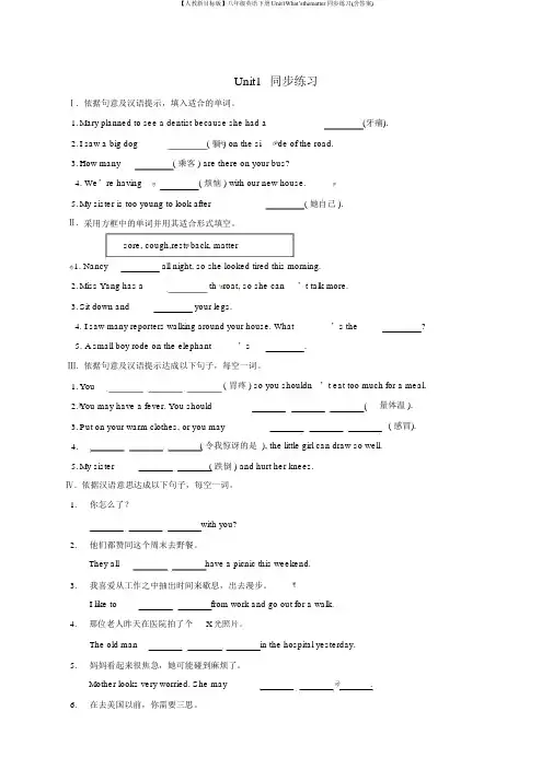
Unit1同步练习Ⅰ.依据句意及汉语提示,填入适合的单词。
1.Mary planned to see a dentist because she had a(牙痛).2.I saw a big dog( 躺 ) on the si de of the road.3.How many( 乘客 ) are there on your bus?4. We’re having( 烦恼 ) with our new house.5.My sister is too young to look after( 她自己 ).Ⅱ.采用方框中的单词并用其适合形式填空。
sore, cough,rest, back, matter1. Nancy all night, so she looked tired this morning.2.Miss Yang has a th roat, so she can’t talk more.3.Sit down and your legs.4. I saw many reporters walking around your house. What’s the?5. A small boy rode on the elephant’s.Ⅲ.依据句意及汉语提示达成以下句子,每空一词。
1.You( 胃疼 ) so you shouldn ’t eat too much for a meal.2.You may have a fever. You should(量体温 ).3.Put on your warm clothes, or you may( 感冒).4.( 令我惊讶的是 ), the little girl can draw so well.5.My sister( 跌倒 ) and hurt her knees.Ⅳ.依据汉语意思达成以下句子,每空一词。
1.你怎么了?with you?2.他们都赞同这个周末去野餐。
Unit 1 Lifestyles 词汇篇 11 、掌握第一单元第一课及第二课的重点单词,短语及句型。
2、灵活运用第一单元第一课及第二课的重点单词,短语及句型。
1.matter vi. 要紧,有重大关系①要紧,有重大关系Does it matter if we ’ re a bit late? 我们晚到一会又关系吗?②事件,问题;课题What’s the matter if we ’re a bit late?短语拓展:③as a matter of fact 事实上,实际上(=in fact)④to make matters/things worse 更糟糕的是⑤It doesn’ t matter. 没关系2.peaceful adj. 和平的,平静的词汇拓展:①peacefully adv. 和平地,平静地②peace n. 和平,宁静,平静短语拓展:③in peace 平静地,和平地Don ’t disturb her. Just leave her in peace. 不要打扰她。
让她安静一会儿。
④at peace 处于和平的,平静的状态She is at peace with her neighbors. 她和邻居们相处融洽。
3.relaxing adj. 轻松的,放松的词汇拓展:①relax v. (使)放松,松开,松懈②relaxation n. 消遣,休息,(对规章制度的)放宽,放松易混辨析:relaxing (物)令人放松的,令人轻松愉快的relaxed (人)感到轻松的,放松的I find cooking relaxing. 我发现烹饪令人放松。
The warm sunshine makes everyone relaxed. 暖和的阳关是大家很放松。
4.suppose vt. 猜想,认为①suppose sb./sth. to be ... 认为某人/某物是...I suppose him to be rich. 我认为他很富有。
Unit 1 What's the matter?班级:________ 姓名:________ 得分:________(测试时间:90分钟总分:120分)听力部分(共20分)一、听句子或对话,根据所听内容选择最佳应答句。
句子或对话念两遍。
(共5小题,每小题1分,满分5分)( )1.A.I have a pen.B.I have a toothache.C.It’s great.【答案】B【听力】What’s the matter, Frank?( )2.A.Yes, she is.B.I’m happy to hear that.C.She should go to see a doctor.【答案】C【听力】Lucy has a bad fever.( )3.A.Three days ago.B.Three days later.C.For three days.【答案】A【听力】When did your sore throat begin?( )4.A.I eat healthy food.B.I’m at school.C.I’m much better. Thank you.【答案】C【听力】How are you feeling now, Tom?( )5.A.I hope so.B.Good idea.C.You’re welcome.【答案】B【听力】You should lie down and rest for a few days.二、听对话,根据对话内容选择最佳答案。
对话念两遍。
(共5小题,每小题1分,满分5分)( )6.What’s the matter with the woman?A.She is stressed out.B.She can’t sleep well.C.She has a cold.【答案】C【听力】M:Why are you taking the medicine?W:Because I have a bad cold.( )7.Which part did Cindy hurt?A.Her leg.B.Her arm.C.Her foot.【答案】A【听力】M:Where is Cindy? Did you see her?W:No, she fell down the stairs and hurt her leg. She is in hospital now. I want to cheer her up. Would you like to go with me?( )8.What did Jim do last weekend?A.He went to the movies.B.He played tennis.C.He danced with friends.【答案】B【听力】W:I went to the movies last weekend. How about you, Jim?M:I played tennis with my friends.( )9.What did the boy do last night?A.He played computer games.B.He watched the basketball game on TV.C.He did his homework.【答案】B【听力】W:Did you do your homework last night?M:No, I didn’t. I watched a basketball game on TV. It’s very interesting.( ) 10.Who is the woman?A.The boy’s grandma.B.The boy’s mother.C.The boy’s aunt.【答案】C【听力】W:Is this your mother?M:No, this is my aunt Gina.三、听短文,根据所听内容选择最佳答案。
新人教版初二下册英语知识点归纳:Unit-1-What’s-the-matter一.询问某人患了何种疾病或遇到什么费事时,常用以下句型:1.What’s the matter 〔with sb〕?2. What’s the trouble / problem〔with sb〕?3.What’s wrong 〔with sb〕? 你怎么了?4. What’s one’s trouble / problem ?5.What’s up ?6. What happened to sb ?7.Are you OK ? 8. Is there anything wrong with sb ?二.表达身体不适或疼痛时,常用以下构造:1.Sb + have /has + a / an + 疾病名称:have acold(患感冒)/ fever / cough / temperature注:have a cold相当于get a cold/catch a cold/have got a cold;have a bad cold(患重感冒);have a heart problem 有心脏病2.Sb + have/ has a sore +身体部位:have a sore throat / back3.Sb + have / has+ a+ 身体部位+ache(构成疾病名词)have a toothache /headache / stomachache / earache /backache4.Sb + hurt(s) +身体部位/ oneself ; He hurt his leg .或身体部位+ hurts ; My head hurts badly .5.There is someth ing wrong with one’s +身体部位。
6.Sb +have /has a pain in one’s +身体部位三.情态动词should / should’t 的用法:意为’应该,应当’ 后接动词原形,无人称和数的变化。
Unit 1 What’s the matte r?一、基础知识1. What’ s the matter?怎么啦?出什么事情了?【解析】matter/ ' mætə(r)) /n.问题;事情What’ s the matter with you?= What’s the trouble with you? = What’s the problem with you?=What’ s wrong with you? 你怎么了?【注】:matter 和trouble 为名词,其前可加the 或形容词性物主代词,wrong 是adj. 不能加the【使用办法】用于问询某人有什么病或某人碰到什么麻烦、问题其后跟问询对象时,与介词with连用。
即:What’s the matter with sb.? = What’s your trouble? = What’s up? = What happens to sb.?—What’s the matter with you ?— I have a bad cold.2. I had a cold.我感冒了。
have a cold=catch a cold=have the flu感冒have a fever 发热have a cough咳嗽have a stomachache胃疼,肚子疼have a toothache牙疼have a headache头疼3. 身体部位+ ache(疼痛)构成新旳复合词stomach+ache=stomachache head+ache=headache tooth+ache=toothache back+ache=backache后背痛ear+ache=earache耳朵痛4. much too+ 形容词,意为太...... ,too much+名词,意为诸多,大量。
5. enough【形容、副词】足够旳/地,enough放在名前,形副后。
A Compatibility This appendix presents some of the practical details that you need to know to be able to use Verilog-A/MS with the simulators available that support it. It starts by describ-ing what constructs to avoid with purely digital models in order to retain compatibility with traditional Verilog-HDL simulators. Then, the issues involved when using S PICE models from Verilog-A/MS are discussed. Finally, it describes specifically how to use Verilog-A and Verilog-AMS in the Cadence simulators: Spectre and AMS D esigner.Spectre was the first simulator to support Verilog-A. It is currently the most popular simulator, and was used to validate each of the Verilog-A models contained in this book. Similarly, AMS Designer was the first simulator to support Verilog-AMS, is currently the most popular simulator that does so, and was used to validate each of the Verilog-AMS models given in this book.1Verilog-HDL CompatibilityWhen describing purely digital modules, it is often desirable to completely avoid the use of the AMS extensions so that the models can be read by a Verilog-HDL simula-tor without modification. In these cases, one should consciously avoid the following constructs.1.2.3.4.8.Explicit parameter type declarationsParameter range limitsAnalog declarations such as disciplines, natures, branches and ground.Analog processes and the various things associated with them (contributions, ana-log operators, limiting and stimulus functions, etc.)Analog events, such as cross, timer, initial_step and final_step.Analog functionsSystem functions and tasks that were added to support analog or mixed-signal modeling, such as $abstime, analysis, $bound_step,$discontinuity, the $driver_…functions, $limexp, the $rdist_… functions, $temperature, and $vt .The wreal wire type5.6.7.Appendix A CompatibilityConnect modules and connect rulesS PICE is not a single language, but rather is a family of related languages. The first widely used version of S PICE was S PICE 2g6 from the University of California at Ber-keley. However, S PICE has been enhanced and distributed by many different compa-nies, each of which has added their own extensions to the language and the models.As a result, there is a great deal of incompatibility even among the S PICE languages themselves.Verilog-A/MS makes no judgment as to which of the various S PICE languages should be supported. Instead, it states that if a simulator that supports Verilog-A/MS is also able to read S PICE netlists of a particular flavor, then certain objects defined in that flavor of S PICE netlist can be referenced from within a Verilog-A/MS structural description. In particular, S PICE models and subcircuits can be instantiated within a Verilog-A/MS module. This is also true for most of the S PICE primitives that are built into the simulator.2369.2S PICE CompatibilityA t some point all circuit simulators such as S PICE will understand Verilog-A, all device models will be available as Verilog-A modules, and model files and netlists will be readily available in Verilog formats; but not today. Until that day, simulators that support Verilog-A/MS must provide the ability to access S PICE primitives from a Verilog description. This section describes how access to S PICE built-in primitives is provided from the Verilog-A/MS language.2.1Scope of Compatibility2.1.1Degree of IncompatibilityThere are four primary areas of incompatibility between versions of S PICE simulators.1.T he version of the S PICE language accepted by various simulators is different and to some degree proprietary.This issue is not addressed by Verilog-A/MS. So whether a particular Verilog-A/MS simulator is S PICE compatible, and with which particular variant of S PICE it is compatible, is solely determined by the authors of the simulator.Not all S PICE simulators support the same set of component primitives. A particu-lar S PICE netlist may reference a primitive that is unsupported within a given simu-lator. Verilog-A/MS offers no alternative in this case other than the possibility that if the model equations are known, the primitive can be rewritten as a module.2.2 S PICE CompatibilityIf an implementation of a Verilog-A/MS tool supports S PICE compatibility, it is expected to provide the basic set of S PICE primitives given in Section 2.3 and be able to read S PICE netlists that contain models and subcircuit statements.S PICE primitives built into the simulator are treated in the same manner in Verilog-A/MS as built-in primitives. However, while the Verilog-A/MS built-in primitives are standardized, the S PICE primitives are not. All aspects of S PICE primitives are imple-mentation dependent.In addition to S PICE primitives, it is also possible to access subcircuits and models defined within S PICE netlists. The subcircuits and models contained within the S PICE netlist are treated as module definitions.2373.The names of the built-in S PICE primitives, their parameters, or their ports can dif-fer from simulator to simulator. This is particularly true because many primitives,parameters, and ports are unnamed in S PICE . When instantiating S PICE primitives in Verilog-A/MS, the primitives must, and parameters and ports can, be named.Since there are no established standard names, there is a high likelihood of incom-patibility cropping up in these names.To avoid this, Verilog-A/MS defines a list of names that must be supported for common S PICE primitives when made available within Verilog-A/MS.This list is given in Table 1. However, it is not possible to anticipate all S PICE primitives and parameters that could be supported; so different implementations can end up using different names. This level of incompatibility can be overcome by using wrapper modules to map names.The mathematical description of the built-in primitives can differ. As with the net-list syntax, incompatible enhancements of the models have crept in through the years. Again, Verilog-A/MS offers no solution in this case other than the possibil-ity that if the model equations are known, the primitive can be rewritten as a mod-ule.2.2Accessing S PICE Objects from Verilog-A/MS2.2.1Case SensitivityS PICE netlists are case insensitive, whereas Verilog-A/MS descriptions are case sensi-tive. From within Verilog-A/MS, a mixed-case name matches the same name with an identical case as if it were defined in a Verilog description.However, if no exact match is found, the mixed-case name will match the same name defined within S PICE regardless of the case.4.Appendix A CompatibilityUnlike with S PICE , the first letter of the instance name, in this case Q1 and Q2, is not constrained by the primitive type. For example, they can just as easily be T1 and T 2.The ports and parameters of the BJT are determined by the BJT primitive itself and not by the model statement for the BJT. See Table 1 for more details. The BJT has 3mandatory ports (collector, base, and emitter) and one optional port (the substrate). In the instantiation of Q1, the ports are passed by order. With Q2, the ports are passed by name. In both cases, the optional substrate port is defaulted by simply not giving it.Accessing S PICE Subcircuits. As an example of how a S PICE subcircuit is refer-enced from Verilog-A/MS, consider the following S PICE subcircuit definition of an oscillator.2382.2.2ExamplesAccessing S PICE models. Consider the following S PICE model file being read by a Verilog-A/MS simulator.module diffPair (c1, b1, e, b2, c2);electrical c1, b1, e, b2, c2;vertNP N Q1 (c1, b1, e, );vertNPN Q2 (.c(c2), .b(b2), .e(e));endmodule.model vertnpn npn+bf=80 is=1e-18 rb=100 vaf=50cje=3pf cjc=2pf cjs=2pf tf=0.3ns tr=6nsThis model can be instantiated in a Verilog-A/MS module as follows.subckt ecposc (out gnd)v a vcc gnd 5ie e e gnd 1 maq1 vcc b1 e vcc vertnpnq2 out b2 e out vertnpnl 1 vcc out 1uhc 1 vcc out 1p ic=1c2 out b1 272.7pfc 3 b1 gnd 3nfr 1 b1 gnd 10kc 4 b2 gnd 3nfr 2 b2 gnd 10k.ends ecposcThis oscillator can be referenced from Verilog-A/MS as:module osc (out, gnd);electrical out, gnd;2 S PICE CompatibilityNote that in Verilog-A/MS the name of the subcircuit instance is not constrained to start with X as it is in S PICE .Accessing S PICE Primitives. To show how various S PICE primitives can be accessed from Verilog-A/MS, the subcircuit given above is translated to native Ver-ilog-A/MS.ecpOs c Osc1 (out, gnd);endmodul evsin e #(.dc(5)) Vcc (vcc, gnd);isin e #(.dc(1m)) lee (e, gnd);vertnp n Q1 (vcc, b1, e, vcc);vertnp n Q2 (out, b2, e, out);inducto r #(.I(1u)) L1 (vcc, out);capacito r #(.c(1p), .ic(1)) C1 (vcc, out);capacito r #(.c(272.7p)) C2 (out, b1);capacito r #(.c(3n)) C3 (b1, gnd);resisto r #(.r(10k)) R1 (b1, gnd);capacito r #(.c(3n)) C4 (b2, gnd);resisto r #(.r(10k)) R2 (b2, gnd);modul e ecpOsc (out, gnd);electrica l out, gnd;endmodul e2.3Preferred Primitive, Parameter and Port NamesTable 1 shows the required names for primitives, parameters, and ports that are other-wise unnamed in S PICE . For connection by order instead of by name, the ports and parameters are given in the order listed. The default discipline of the ports for these primitives is electrical and their direction is inout.2392.3.1Unsupported ComponentsVerilog-A/MS does not support the concept of passing an instance name as a parame-ter . As such, the following components are not supported: ccvs, cccs, and mutual 240Appendix ACompatibility3 Spectre Compatibilityinductors; however, these primitives can be instantiated inside a S PICE subcircuit that itself is instantiated in Verilog-A/MS.2.4Other IssuesThere are currently some important unresolved issues with S PICE compatibility in Verilog-A/MS. It is expected that these issues will be resolved when extensions cur-rently under development to support compact semiconductor models are added to the language.2.4.1S PICE Model StatementsThere is currently no Verilog-A/MS equivalent to the S PICE model statement. The way a simulator accesses a library of S PICE models is implementation specific.2.4.2Multiplicity Factor on SubcircuitsS PICE simulators support a multiplicity factor (m) parameter on subcircuits without the parameter being explicitly declared. This factor is typically used to indicate the subcircuit should be modeled as if there are a specified number of copies wired in par-allel. If supported by the implementation, the automatic multiplicity factors are sup-ported for subcircuits defined in S PICE, but not for subcircuits defined as modules in Verilog-A/MS. Thus, if the S PICE subcircuit given in Section 2.2 is instantiated, a multiplicity factor could be specified (assuming the simulator implementation sup-ports multiplicity factors on S PICE subcircuits). However, a multiplicity factor cannot be specified when instantiating the equivalent Verilog-A/MS module,also given in Section 2.2.3Spectre CompatibilitySpectre was the first simulator to support Verilog-A, and is still by far the most popu-lar. It was also the simulator used to validate all of the Verilog-A models in this book.3.1Using Verilog-A with SpectreWhen Spectre starts up, it reads either a Spectre or S PICE netlist. That netlist includes the top-level of the design, along with the various control statements. Those control statements specify the simulator settings and any analyses to be performed. In addi-tion, the desired model and Verilog-A files would be referenced from this file. When Spectre reads a reference to a Verilog-A file, it makes the components defined within that file available to the design. In other words,referencing a Verilog-A file241Appendix A Compatibility does not instantiate the components described in the file into the design. Rather, it loads the components and makes them available for instantiation into the design. Once a Verilog-A component has been loaded into Spectre, it can be instantiated in the same manner as any other component. This is illustrated in the Spectre netlist shown below.Example:// Test circuit for quantizersimulator lang=spectreahdl_include “quantizer.va”Vclk (clk 0) vsource type=pulse val1=1 period=1usVin (in 0) vsource type=sine ampl=1 freq=5kHz sinephase=45Quantizer (out in clk) quantizer levels=21 vh=1 vl=–1 vth=0.5 tt=10nssave in out Quantizer:levelsineResp tran stop=200uSThe first line in this file is a comment, as it must be, and the second specifies that the Spectre netlist format is used in the file. The third line opens the Verilog-A file quan-tizer.va and loads the model found in this file. It contains the module quantizer, shown in Listing 1.The next three lines instantiate the three components thatmake up the design. Vin, Vclk, and Quantizer. Vin andVclk are Spectre primitive voltage sources and Quantizeris the Verilog-A model from Listing 1. Within Spectreand S PICE netlists, nodes are associated with ports by theorder in which they are given. Thus for the quantizer, thenodes out, in, and clk are associated with the ports with the same names, but the fact that the names match is a coincidence, it is the order that determines the association. So the first node given is associated with the first port, and so on. Parameters are asso-ciated by name, and any parameters that are left unspecified take their default values. The final two lines are control statements for Spectre. The first specifies which signals should be saved for later display or analysis. In this case,three signals are saved, in, out and Quantizer:level. The signals in and out are nodes, and Spectre will save the voltages on these nodes for each analysis. Quantizer:level saves the value of the vari-able level from Quantizer for each analysis. This is a feature of Spectre that can be used when debugging a module. The final statement specifies that a transientanalysis named sineResp should be run.If this netlist is contained in a file named quantizer.scs (the .scs suffix stands for Spec-tre circuit simulator), it can be run in Spectre using2423Spectre CompatibilityLISTING 1N-level quantizer model (like an ADC followed by a DAC).`include "disciplines. vams"module quantizer (out, in, clk);parameter integer levels =2 from [2:inf );// number of quantization levelsparameter real vh = +1;// voltage of highest level (V)parameter real vl = –1 from (–inf :vh);// voltage of lowest level (V)parameter real vth = (vh + vl)/2;// threshold voltage of clock (V)parameter integer dir = +1 from [–1:+1] exclude 0;//if dir=+1, rising clock edge triggers// if dir=–1, falling clock edge triggersparameter real td = 0 from [0:inf ); // output delay (s)parameter real tt = 0 from [0:inf ); // output transition time (s)outpu t out; voltage out;// outputinpu t in; voltage in;// inputinpu t clk; voltage clk;// clock input (edge triggered)rea l quantized, delta;i ntege r level;analog begin@(cross (V(clk) – vth, dir) or initial _step ) begindelta = (vh–vl)/(levels–1);level = (V(in) – vl)/delta;if (level < 0)level = 0;else if (level >= levels)level = levels – 1;quantized = level * delta + vl;endV(out) <+ transition ( quantized, td, tt );endendmodulespectre quantizer.scsfrom a Unix shell. More information about using Spectre can be found in [19].Busses. Verilog-A allows busses as ports but the Spectre netlist language does not support busses. When instantiating a Verilog-A model that includes a bus as a port from within a Spectre netlist, each member of the bus must be individually listed in the terminal list. As an example, consider a netlist that instantiates the ADC and DAC given in Listings 26 and 27 from Chapter 3.243Appendix A Compatibility Example:// Test ADC and DAC modelssimulator lang=spectreahdl_include “adc2.vams”ahdl_include “dac2.vams”Vi n (in 0) vsource type=sine ampl=0.5 dc=0.5 freq=1Vcl k (clk 0) vsource type=pulse val0=0 val1=1 period=1msAD C (b7 b6 b5 b4 b3 b2 b1 b0 in clk) adc bits=8 vdd=1 td=100us tt=100usDA C (out b7 b6 b5 b4 b3 b2 b1 b0 clk) dac bits=8 vdd=1 td=100us tt=100ussineRes p tran stop=1Here the 8-bit bus that connects the output of the ADC to the input of the DAC con-sists of 8 nodes, b0 to b7, that are individually specified on the terminal list for both the ADC and DAC.3.2Accessing Spectre Objects from Verilog-AIn the last section, it was shown how to access Verilog-A models from a Spectre net-list. The converse is also possible; one can access Spectre primitives, subcircuits, and models from a Verilog-A netlist. This process was sketched out for S PICE in Section 2. Some of the details are a bit different with Spectre as it provides access to a broader variety of components and because the way Spectre implements its independent sources is a bit different from S PICE.Any Spectre objects that are to be instantiated in a Verilog-A netlist must be defined, either in the Spectre netlist, or in the Spectre simulator itself, before they can be instantiated in a Verilog-A module.There is no way to specify a model statement or model parameters (as opposed to instance parameters) from within the Verilog-A language. However, it is possible to instantiate an instance that references a model from within Verilog-A. For example the Spectre modelmode l vertNPN bjt type=npn bf=80 is=1e-18 rb=100 vaf=50 \cje=3p f cjc=2pf cjs=2pf tf=0.3ns tr=6nscan be instantiated in a Verilog-A/MS module as followsmodul e diffPair (c1, b1, e, b2, c2);electrica l c1, b1, e, b2, c2;paramete r real area=1 from (0:inf);2443 Spectre CompatibilityvertNPN Q1 (c1, b1, e,);vertNPN Q2 (.c(c2), .b(b2), .e(e));endmoduleOne thing to take notice of is that by default the Spectre netlist language is case sensi-tive, thus when referring to a name defined in the Spectre netlist from a Verilog net-list, the case of the characters used in the name must match between the two languages.In a very similar manner, one can access subcircuits defined in a Spectre netlist from Verilog. Consider the above module implemented as a Spectre subcircuit.subckt diffPair (c1, b1, e, b2, c2)parameter area=1Q1 (c1 b1 e) vertNPN area=area;Q2 (c2 b2 e) vertNPN area=area;ends diffPairThis subcircuit can be instantiated in a Verilog-A netlist usingdiffPair #(.area(10)) DP1(o1, i1, tail, i2, o2);Notice that you can specify values for Spectre subcircuit parameters.Finally, any Spectre built-in components that use only real-valued, string-valued, or vector-valued parameters can be accessed from Verilog-A. This precludes direct use of current controlled and mutual inductors, but they can be used if bundled in subcir-cuits. The names used for the ports (terminals) and parameters can be determined by using Spectre’s help facility. For example, to find the names needed to instantiate Spectre’s multi-conductor lossy transmission line, runspectre -help mtlineat the Unix command prompt. It will describe the mtline component, and the descrip-tion will give the names of the ports and parameters. From Verilog-A, the mtline can be instantiated withmtline #(.len(0.01), .r({0.3,0.0,0.3}), .c((0.35p, -0.03p, 0.35p})) x1 (a1, b1, a2, b2, gnd, gnd); Spectre provides access to its independent sources in a manner somewhat different from that described in Section 2.3. Rather than encoding the wave shape in the name of the primitive, Spectre bases the name of the primitive only on the type of source, and adds an additional parameter that specifies the wave shape. For example, Section 2.3 indicates that instantiating a sinusoidal voltage source from S PICE would be done as follows,vsine #(.ampl(1), .freq(1G)) Vin (in, gnd);245Appendix A Compatibilitybut with Spectre you would usevsource #(.type(“sine”), .ampl(1), .freq(1G)) Vin (in, gnd);The benefit of this approach is that the wave shape itself is parameterized. It is possi-ble to give the parameters for multiple wave shapes, and then select which wave shape to use with the type parameter. The list of Spectre source parameters is given in Table 2.2463 Spectre Compatibility3.3Spectre’s Implementation of Verilog-ACurrently Spectre supports a somewhat restricted version of the Verilog-A language. In particular, the following limitations exist in the Spectre implementation.1.2.3. 4. 5. 6. 7.8.9.When instantiating modules, parameter values can only be passed by name and not by order. Furthermore, nets can only be associated with ports by order, not by name.The genvar type of integers is not supported. Nor are analog operators allowed in for loops. Instead the deprecated generate statement remains available and should be used when analog operators must be contained within a loop.The ground statement is not supported. You should pass in ground as a terminal. Argument and port lists cannot contain skipped arguments.Using parameter values as array sizes is not allowed.It is not possible to pass strings as parameters into a Verilog-A module.When declaring vector ports, array bounds must be given on both type and direc-tion declarations.The delay and zi_… functions do not work in any small-signal frequency-domain analyses.The small signal stimulus functions cannot be used in assignment statements or in expressions. They must instead be isolated in a contribution statement. So, rather than scaling the output of the noise functions, you should specify the desired out-put power using the primary operand of the functions. For example, consider mod-eling oscillator phase noise for use with SpectreRF.Assume that ampl, freq, and pn are parameters and that phase is a real variable set such thatphas e = 2*`M_PI*freq*$abstime;Then the simplest way of modeling phase noise is to simply add noise to the argu-ment used to convert phase to voltage, in this case cos().247Appendix A CompatibilityV(out) <+ ampl*cos(phase + flicker_noise(pn,2));But this is not supported as the flicker_noise function is not isolated on the contri-bution statement. Since the flicker_noise output is by definition small, it can be removed from the argument of the cos() function by using the Taylor series to expand the function into a power series and then truncating the higher order terms.This naturally leads to something likeV(out) <+ ampl*(cos(phase) + sin(phase)*flicker_noise(pn,2));However,even this is not supported as the output of the flicker_noise function is being further processed before it reaches the contribution operator. Instead, both factors that are applied to the flicker_noise function must be applied directly to the operand.V(out) <+ ampl*cos(phase) + flicker_noise(pn*ampl*sin(phase),2);This is acceptable even though the flicker_noise function is not alone in the contri-bution statement because it is isolated.10.The output of the derivative operator, ddt, must have linear accessibility to abranch. Meaning that its output can be directly contributed to a branch, or it can be scaled by a constant factor, but it cannot be multiplied by a signal dependent quan-tity or passed through a nonlinear operator before being contributed to a branch.So for example,l(p,n) <+ ddt(c*V(p,n));l(p,n)<+c*ddt(V(p,n));icap = c*ddt(V(p,n));l(p,n) <+ V(p,n)/r + icap;are all acceptable, butl(p,n)<+c0*(1+c1*(V(p,n)–v0))*ddt(V(p,n));is not because the output of the ddt operator is being multiplied by a quantity that is dependent on the value of a continuous-time signal. To avoid this problem the model must either be reformulated [20] or a node must be created internal to the model to hold the output of the ddt operator. Then the nonlinear operation would be performed on the value of the node rather than directly on the output of the ddt operator.4AMS Designer CompatibilityCadence’s AMS Designer is both a simulator and an environment. The simulator implements the full Verilog-AMS language and was used to validate the mixed-signal 2484 AMS Designer Compatibilitymodels provided in this book. The environment is the interface between the Cadence Design Framework II (DFII) and the simulator. It is used to netlist schematics into Verilog-AMS format, to create the design configurations, and to run the simulator. The Verilog-AMS language is the primary design language within AMS designer; meaning that it is used for both netlisting and as the modeling language. In addition, AMS Designer is a multilingual simulator that also supports VHDL-AMS, SystemC, SystemVerilog, and Spectre and S PICE netlists.The following describes how the examples in this book can be used with the simulator by providing necessary instruction on how to set-up an AMS simulation. Basic instructions are given for using the AMS Designer simulator in a stand-alone mode. The product documentation available from Cadence provides complete and detailed help on how to use the simulator as well as instruction on how to use the AMS Designer environment.4.1Using Verilog-AMS with AMS DesignerThe AMS Designer simulator is built upon NC-S IM technology. Both share a common library concept and format.4.1.1General SetupTo use a Verilog-AMS model it must be compiled into one of the libraries defined in the cds.lib file (see Listing 2) located in the working directory. In this file, ‘#’ is used to introduce a comment: anything that follows up until the end of the line is ignored. The file consists of commands, one per line. The include command is replaced by the contents of the file it references. In this case, it includes the contents of the cds.lib file that comes with the simulator installation. This file references the libraries that are delivered with the simulator. An example of such a library is connectLib, which con-tains definitions of various interface components with different accuracy levels. The ‘$’ introduces a Unix environment variable substitution. In this case, AMSHOME would contain the full path to the installation directory for the AMS Designer simula-tor. The define command declares that the Unix directory worklib in the working directory shall be used as the library directory for the library with the name worklib. LISTING 2 Sample cds.lib file# cds.libinclud e $AMSHOME/tools/inca/files/cds.libdefin e worklib ./worklib249Appendix A Compatibility Another important setup file is hdl.var. Place tool options that are often used into this file rather than specifying them on the command line every time a model file is com-piled or a design is elaborated. Listing 3 shows an example hdl.var file. The include statement incorporates the default simulator settings. The first define statement declares that the name worklib, which was declared within the cds.lib file, is defined as the working library. WORK is a keyword, worklib is the name of the existing library. This causes models to be compiled into this library if no other target library is specified as a command line argument during compilation. The second define state-ment causes the compiler to write information into the library necessary for source code debugging.LISTING 3 Sample hdl.var file# hdl.varinclude $AMSHOME/tools/inca/files/hdl.vardefine WORK worklibdefine NCVLOGOPTS -linedebug4.1.2 CompilationAssume that the cds.lib and hdl.var files given above are found in a directory that con-tains the Verilog-AMS model vco.vams. From within this directory, this model can be compiled usingncvlog -ams vco.vamsor in case the working library is not preset or it should be compiled into a library other than the default working libraryncvlog -ams -work worklib vco.vamsThe command line argument “-ams” is necessary to compile Verilog-AMS models. Compilation without this argument compiles Verilog-HDL models only. When com-piling several source files the order in which they are compiled is arbitrary. If there are syntax errors, ncvlog will print error messages that direct you to the point in the file where the error was detected. For a quick command line reference you can use ncvlog -helpAn example PLL-design is shown in Listing 4; it references modules defined in List-ings 5-8.Every module is written into a separate file in the working library. The design is compiled with the compilation script shown in Listing 9. The phase-fre-quency detector module (pfd) and the frequency divider module (fd) are compiled 250。