龙门式起重机外文翻译、中英文翻译、外文文献翻译
- 格式:doc
- 大小:638.00 KB
- 文档页数:21

European Journal of Scientific ResearchISSN 1450-216X Vol.33 No.4 (2009>, pp.630-641© EuroJournals Publishing, Inc. 2009对龙门起重机系统抑制摇摆的最优跟踪控制M.A. AhmadControl and Instrumentation Research Group (COINS>,Faculty of Electrical and Electronics EngineeringUniversiti Malaysia Pahang, Lebuhraya Tun Razak26300, Kuantan, Pahang, MalaysiaE-mail:Tel: +609-5492366。
Fax: +609-5492377R.M.T. Raja IsmailControl and Instrumentation Research Group (COINS>Faculty of Electrical and Electronics EngineeringUniversiti Malaysia Pahang, Lebuhraya Tun Razak26300, Kuantan, Pahang, MalaysiaE-mail:Tel: +609-5492366。
Fax: +609-5492377M.S. RamliControl and Instrumentation Research Group (COINS>Faculty of Electrical and Electronics EngineeringUniversiti Malaysia Pahang, Lebuhraya Tun Razak26300, Kuantan, Pahang, MalaysiaE-mail:Tel: +609-5492366。

起重机中英⽂对照外⽂翻译⽂献中英⽂对照外⽂翻译(⽂档含英⽂原⽂和中⽂翻译)Control of Tower Cranes WithDouble-Pendulum Payload DynamicsAbstract:The usefulness of cranes is limited because the payload is supported by an overhead suspension cable that allows oscilation to occur during crane motion. Under certain conditions, the payload dynamics may introduce an additional oscillatory mode that creates a double pendulum. This paper presents an analysis of this effect on tower cranes. This paper also reviews a command generation technique to suppress the oscillatory dynamics with robustness to frequency changes. Experimental results are presented to verify that the proposed method can improve the ability of crane operators to drive a double-pendulum tower crane. The performance improvements occurred during both local and teleoperated control.Key words:Crane , input shaping , tower crane oscillation , vibrationI. INTRODUCTIONThe study of crane dynamics and advanced control methods has received significant attention. Cranes can roughly be divided into three categories based upontheir primary dynamic properties and the coordinate system that most naturally describes the location of the suspension cable connection point. The first category, bridge cranes, operate in Cartesian space, as shown in Fig. 1(a). The trolley moves along a bridge, whose motion is perpendicular to that of the trolley. Bridge cranes that can travel on a mobile base are often called gantry cranes. Bridge cranes are common in factories, warehouses, and shipyards.The second major category of cranes is boom cranes, such as the one sketched in Fig. 1(b). Boom cranes are best described in spherical coordinates, where a boom rotates aboutaxes both perpendicular and parallel to the ground. In Fig. 1(b), ψis the rotation aboutthe vertical, Z-axis, and θis the rotation about the horizontal, Y -axis. The payload is supported from a suspension cable at the end of the boom. Boom cranes are often placed on a mobile base that allows them to change their workspace.The third major category of cranes is tower cranes, like the one sketched in Fig. 1(c). These are most naturally described by cylindrical coordinates. A horizontal jib arm rotates around a vertical tower. The payload is supported by a cable from the trolley, which moves radially along the jib arm. Tower cranes are commonly used in the construction of multistory buildings and have the advantage of having a small footprint-to-workspace ratio. Primary disadvantages of tower and boom cranes, from a control design viewpoint, are the nonlinear dynamics due to the rotational nature of the cranes, in addition to the less intuitive natural coordinate systems.A common characteristic among all cranes is that the pay- load is supported via an overhead suspension cable. While this provides the hoisting functionality of the crane, it also presents several challenges, the primary of which is payload oscillation. Motion of the crane will often lead to large payload oscillations. These payload oscillations have many detrimental effects including degrading payload positioning accuracy, increasing task completion time, and decreasing safety. A large research effort has been directed at reducing oscillations. An overview of these efforts in crane control, concentrating mainly on feedback methods, is provided in [1]. Some researchers have proposed smooth commands to reduce excitation of system flexible modes [2]–[5]. Crane control methods based on command shaping are reviewed in [6]. Many researchers have focused on feedback methods, which necessitate the addition necessitate the addition of sensors to the crane and can prove difficult to use in conjunction with human operators. For example, some quayside cranes have been equipped with sophisticated feedback control systems to dampen payload sway. However, the motions induced by the computer control annoyed some of the human operators. As a result, the human operators disabled the feedback controllers. Given that the vast majority of cranes are driven by human operators and will never be equipped with computer-based feedback, feedback methods are not considered in this paper.Input shaping [7], [8] is one control method that dramatically reduces payload oscillation by intelligently shaping the commands generated by human operators [9], [10]. Using rough estimates of system natural frequencies and damping ratios, a series of impulses, called the input shaper, is designed. The convolution of the input shaper and the original command is then used to drive the system. This process is demonstrated with atwo-impulse input shaper and a step command in Fig. 2. Note that the rise time of the command is increased by the duration of the input shaper. This small increase in the rise time isnormally on the order of 0.5–1 periods of the dominant vibration mode.Fig. 1. Sketches of (a) bridge crane, (b) boom crane, (c) and tower crane.Fig. 2. Input-shaping process.Input shaping has been successfully implemented on many vibratory systems including bridge [11]–[13], tower [14]–[16], and boom [17], [18] cranes, coordinate measurement machines[19]–[21], robotic arms [8], [22], [23], demining robots [24], and micro-milling machines [25].Most input-shaping techniques are based upon linear system theory. However, some research efforts have examined the extension of input shaping to nonlinear systems [26], [14]. Input shapers that are effective despite system nonlinearities have been developed. These include input shapers for nonlinear actuator dynamics, friction, and dynamic nonlinearities [14], [27]–[31]. One method of dealing with nonlinearities is the use of adaptive or learning input shapers [32]–[34].Despite these efforts, the simplest and most common way to address system nonlinearities is to utilize a robust input shaper [35]. An input shaper that is more robust to changes in system parameters will generally be more robust to system nonlinearities that manifest themselves as changes in the linearized frequencies. In addition to designing robust shapers, input shapers can also be designed to suppress multiple modes of vibration [36]–[38].In Section II, the mobile tower crane used during experimental tests for this paper is presented. In Section III, planar and 3-D models of a tower crane are examined to highlight important dynamic effects. Section IV presents a method to design multimode input shapers with specified levels of robustness. InSection V, these methods are implemented on a tower crane with double-pendulum payload dynamics. Finally, in Section VI, the effect of the robust shapers on human operator performance is presented for both local and teleoperated control.II. MOBILE TOWER CRANEThe mobile tower crane, shown in Fig. 3, has teleoperation capabilities that allow it to be operated in real-time from anywhere in the world via the Internet [15]. The tower portion of the crane, shown in Fig. 3(a), is approximately 2 m tall with a 1 m jib arm. It is actuated by Siemens synchronous, AC servomotors. The jib is capable of 340°rotation about the tower. The trolley moves radially along the jib via a lead screw, and a hoisting motor controls the suspension cable length. Motor encoders are used for PD feedback control of trolley motion in the slewing and radial directions. A Siemens digital camera is mounted to the trolley and records the swing deflection of the hook at a sampling rate of 50 Hz [15].The measurement resolution of the camera depends on the suspension cable length. For the cable lengths used in this research, the resolution is approximately 0.08°. This is equivalent to a 1.4 mm hook displacement at a cable length of 1 m. In this work, the camera is not used for feedback control of the payload oscillation. The experimental results presented in this paper utilize encoder data to describe jib and trolley position and camera data to measure the deflection angles of the hook. Base mobility is provided by DC motors with omnidirectional wheels attached to each support leg, as shown in Fig. 3(b). The base is under PD control using two HiBot SH2-based microcontrollers, with feedback from motor-shaft-mounted encoders. The mobile base was kept stationary during all experiments presented in this paper. Therefore, the mobile tower crane operated as a standard tower crane.Table I summarizes the performance characteristics of the tower crane. It should be noted that most of these limits areenforced via software and are not the physical limitations of the system. These limitations are enforced to more closely match theoperational parameters of full-sized tower cranes.Fig. 3. Mobile, portable tower crane, (a) mobile tower crane, (b) mobile crane base.TABLE I MOBILE TOWER CRANE PERFORMANCE LIMITSFig. 4 Sketch of tower crane with a double-pendulum dynamics.III. TOWER CRANE MODELFig.4 shows a sketch of a tower crane with a double-pendulum payload configuration. The jib rotates by an angle around the vertical axis Z parallelto the tower column. The trolley moves radially along the jib; its position along the jib is described by r . The suspension cable length from the trolley to the hook is represented by an inflexible, massless cable of variable length 1l . The payload is connected to the hook via an inflexible, massless cable of length 2l . Both the hook and the payload are represented as point masses having masses h m and p m , respectively.The angles describing the position of the hook are shown in Fig. 5(a). The angle φrepresents a deflection in the radial direction, along the jib. The angle χ represents a tangential deflection, perpendicular to the jib. In Fig. 5(a), φ is in the plane of the page, and χ lies in a plane out of the page. The angles describing the payload position are shown in Fig. 5(b). Notice that these angles are defined relative to a line from the trolley to the hook. If there is no deflection of the hook, then the angleγ describes radial deflections, along the jib, and the angle α represents deflections perpendicular to the jib, in the tangential direction. The equations of motion for this model were derived using a commercial dynamics package, but they are too complex to show in their entirety here, as they are each over a page in length.To give some insight into the double-pendulum model, the position of the hook and payload within the Newtonian frame XYZ are written as —h q and —p q , respectivelyWhere -I , -J and -K are unit vectors in the X , Y , and Z directions. The Lagrangian may then be written asFig. 5. (a) Angles describing hook motion. (b) Angles describing payload motion.Fig. 6. Experimental and simulated responses of radial motion.(a) Hook responses (φ) for m 48.01=l ,(b) Hook responses for m 28.11=lThe motion of the trolley can be represented in terms of the system inputs. The position of the trolley —tr q in the Newtonian frame is described byThis position, or its derivatives, can be used as the input to any number of models of a spherical double-pendulum. More detailed discussion of the dynamics of spherical double pendulums can be found in [39]–[42].The addition of the second mass and resulting double-pendulum dramatically increases the complexity of the equations of motion beyond the more commonly used single-pendulum tower model [1], [16], [43]–[46]. This fact can been seen in the Lagrangian. In (3), the terms in the square brackets represent those that remain for the single-pendulum model; no —p q terms appear. This significantly reduces the complexity of the equations because —p q is a function of the inputs and all four angles shown in Fig. 5.It should be reiterated that such a complex dynamic model is not used to design the input-shaping controllers presented in later sections. The model was developed as a vehicle to evaluate the proposed control method over a variety of operating conditions and demonstrate its effectiveness. The controller is designed using a much simpler, planar model.A. Experimental V erification of the ModelThe full, nonlinear equations of motion were experimentally verified using several test cases. Fig.6 shows two cases involving only radial motion. The trolley was driven at maximum velocity for a distance of 0.30 m, with 2l =0.45m .The payload mass p m for both cases was 0.15 kg and the hook mass h m was approximately 0.105 kg. The two cases shown in Fig. 6 present extremes of suspension cable lengths 1l . In Fig. 6(a), 1l is 0.48 m , close to the minimum length that can be measured by the overhead camera. At this length, the double-pendulum effect is immediately noticeable. One can see that the experimental and simulated responses closely match. In Fig. 6(b), 1l is 1.28 m, the maximum length possible while keeping the payload from hitting the ground. At this length, the second mode of oscillation has much less effect on the response. The model closely matches the experimental response for this case as well. The responses for a linearized, planar model, which will be developed in Section III-B, are also shown in Fig. 6. The responses from this planar model closely match both the experimental results and the responses of the full, nonlinear model for both suspension cable lengths.Fig. 7. Hook responses to 20°jib rotation:(a) φ (radial) response;(b) χ (tangential) response.Fig. 8. Hook responses to 90°jib rotation:φ(radial) response;(b) χ(tangential) response.(a)If the trolley position is held constant and the jib is rotated, then the rotational and centripetal accelerations cause oscillation in both the radial and tangential directions. This can be seen in the simulation responses from the full nonlinear model in Figs. 7 and 8. In Fig. 7, the trolley is held at a fixed position of r = 0.75 m, while the jib is rotated 20°. This relatively small rotation only slightly excites oscillation in the radial direction, as shown in Fig. 7(a). The vibratory dynamics are dominated byoscillations in the tangential direction, χ, as shown in Fig. 7(b). If, however, a large angular displacement of the jib occurs, then significant oscillation will occur in both the radial and tangential directions, as shown in Fig. 8. In this case, the trolley was fixed at r = 0.75 m and the jib was rotated 90°. Figs. 7 and 8 show that the experimental responses closely match those predicted by the model for these rotational motions. Part of the deviation in Fig. 8(b) can be attributed to the unevenness of the floor on which the crane sits. After the 90°jib rotation the hook and payload oscillate about a slightly different equilibrium point, as measured by the overhead camera.Fig.9.Planardouble-pendulummodel.B.Dynamic AnalysisIf the motion of the tower crane is limited to trolley motion, like the responses shown in Fig. 6, then the model may be simplified to that shown in Fig. 9. This model simplifies the analysis of the system dynamics and provides simple estimates of the two natural frequencies of the double pendulum. These estimates will be used to develop input shapers for the double-pendulum tower crane.The crane is moved by applying a force )(t u to the trolley. A cable of length 1l hangs below the trolley and supports a hook, of mass h m , to which the payload is attached using rigging cables. The rigging and payload are modeled as a second cable, of length 2l and point mass p m . Assuming that the cable and rigging lengths do not change during the motion, the linearized equations of motion, assuming zero initial conditions, arewhere φ and γ describe the angles of the two pendulums, R is the ratio of the payload mass to the hook mass, and g is the acceleration due to gravity.The linearized frequencies of the double-pendulum dynamics modeled in (5) are [47]Where Note that the frequencies depend on the two cable lengths and the mass ratio.Fig. 10. Variation of first and second mode frequencies when m l l 8.121=+.。

附录外文文献原文:The Introduction of cranesA crane is defined as a mechanism for lifting and lowering loads with a hoisting mechanism Shapiro, 1991. Cranes are the most useful and versatile piece of equipment on a vast majority of construction projects. They vary widely in configuration, capacity, mode of operation, intensity of utilization and cost. On a large project, a contractor may have an assortment of cranes for different purposes. Small mobile hydraulic cranes may be used for unloading materials from trucks and for small concrete placement operations, while larger crawler and tower cranes may be used for the erection and removal of forms, the installation of steel reinforcement, the placement of concrete, and the erection of structural steel and precast concrete beams.On many construction sites a crane is needed to lift loads such as concrete skips, reinforcement, and formwork. As the lifting needs of the construction industry have increased and diversified, a large number of general and special purpose cranes have been designed and manufactured. These cranes fall into two categories, those employed in industry and those employed in construction. The most common types of cranes used in construction are mobile, tower, and derrick cranes.1.Mobile cranesA mobile crane is a crane capable of moving under its own power without being restricted to predetermined travel. Mobility is provided by mounting or integrating the crane with trucks or all terrain carriers or rough terrain carriers or by providing crawlers. Truck-mounted cranes have the advantage of being able to move under their own power to the construction site. Additionally, mobile cranes can move about the site, and are often able to do the work of several stationary units.Mobile cranes are used for loading, mounting, carrying large loads and for work performed in the presence of obstacles of various kinds such as power lines and similar technological installations. The essential difficulty is here the swinging of the payload which occurs during working motion and also after the work is completed. This applies particularly to the slewing motion of the crane chassis, for which relatively large angular accelerations and negative accelerations of the chassis are characteristic. Inertia forces together with the centrifugal force and the Carioles force cause the payload to swing as a spherical pendulum. Proper control of the slewing motion of the crane serving to transport a payload to the defined point with simultaneous minimization of the swings when theworking motion is finished plays an important role in the model.Modern mobile cranes include the drive and the control systems. Control systems send the feedback signals from the mechanical structure to the drive systems. In general, they are closed chain mechanisms with flexible members [1].Rotation, load and boom hoisting are fundamental motions the mobile crane. During transfer of the load as well as at the end of the motion process, the motor drive forces, the structure inertia forces, the wind forces and the load inertia forces can result in substantial, undesired oscillations in crane. The structure inertia forces and the load inertia forces can be evaluated with numerical methods, such as the finite element method. However, the drive forces are difficult to describe. During start-up and breaking the output forces of the drive system significantly fluctuate. To reduce the speed variations during start-up and braking the controlled motor must produce torque other than constant [2,3], which in turn affects the performance of the crane.Modern mobile cranes that have been built till today have oft a maximal lifting capacity of 3000 tons and incorporate long booms. Crane structure and drive system must be safe, functionary and as light as possible. For economic and time reasons it is impossible to build prototypes for great cranes. Therefore, it is desirable to determinate the crane dynamic responses with the theoretical calculation.Several published articles on the dynamic responses of mobile crane are available in the open literature. In the mid-seventies Peeken et al. [4] have studied the dynamic forces of a mobile crane during rotation of the boom, using very few degrees of freedom for the dynamic equations and very simply spring-mass system for the crane structure. Later Maczynski et al. [5] studied the load swing of a mobile crane with a four mass-model for the crane structure. Posiadala et al. [6] have researched the lifted load motion with consideration for the change of rotating, booming and load hoisting. However, only the kinematics were studied. Later the influence of the flexibility of the support system on the load motion was investigated by the same author [7]. Recently, Kilicaslan et al. [1] have studied the characteristics of a mobile crane using a flexible multibody dynamics approach. Towarek [16] has concentrated the influence of flexible soil foundation on the dynamic stability of the boom crane. The drive forces, however, in all of those studies were presented by using so called the metho d of ……kinematics forcing‟‟ [6] with assumed velocities or accelerations. In practice this assumption could not comply with the motion during start-up and braking.A detailed and accurate model of a mobile crane can be achieved with the finite element method. Using non-linear finite element theory Gunthner and Kleeberger [9] studied the dynamic responses of lattice mobile cranes. About 2754 beam elements and 80 truss elements were used for modeling of the lattice-boom structure. On this basis a efficient software for mobile crane calculation––NODYA has been developed. However, the influences of the drive systems must be determined by measuring on hoisting of the load[10], or rotating of the crane [11]. This is neither efficient nor convenient for computer simulation of arbitrary crane motions.Studies on the problem of control for the dynamic response of rotary crane are also available. Sato et al. [14], derived a control law so that the transfer a load to a desired position will take place that at the end of the transfer of the swing of the load decays as soon as possible. Gustafsson [15] described a feedback control system for a rotary crane to move a cargo without oscillations and correctly align the cargo at the final position. However, only rigid bodies and elastic joint between the boom and the jib in those studies were considered. The dynamic response of the crane, for this reason, will be global.To improve this situation, a new method for dynamic calculation of mobile cranes will be presented in this paper. In this method, the flexible multibody model of the steel structure will be coupled with the model of the drive systems. In that way the elastic deformation, the rigid body motion of the structure and the dynamic behavior of the drive system can be determined with one integrated model. In this paper this method will be called ……complete dynamic calculation for driven “mechanism”.On the basis of flexible multibody theory and the Lagrangian equations, the system equations for complete dynamic calculation will be established. The drive- and control system will be described as differential equations. The complete system leads to a non-linear system of differential equations. The calculation method has been realized for a hydraulic mobile crane. In addition to the structural elements, the mathematical modeling of hydraulic drive- and control systems is decried. The simulations of crane rotations for arbitrary working conditions will be carried out. As result, a more exact representation of dynamic behavior not only for the crane structure, but also for the drive system will be achieved. Based on the results of these simulations the influences of the accelerations, velocities during start-up and braking of crane motions will be discussed.2.Tower cranesThe tower crane is a crane with a fixed vertical mast that is topped by a rotating boom and equipped with a winch for hoisting and lowering loads (Dickie, 990). Tower cranes are designed for situations which require operation in congested areas. Congestion may arise from the nature of the site or from the nature of the construction project. There is no limitation to the height of a high-rise building that can be constructed with a tower crane. The very high line speeds, up to 304.8 mrmin, available with some models yield good production rates at any height. They provide a considerable horizontal working radius, yet require a small work space on the ground (Chalabi, 1989). Some machines can also operate in winds of up to 72.4 km/h, which is far above mobile crane wind limits.The tower cranes are more economical only for longer term construction operations and higher lifting frequencies. This is because of the fairly extensive planning needed for installation, together with the transportation, erection and dismantling costs.3. Derrick cranesA derrick is a device for raising, lowering, and/or moving loads laterally. The simplest form of the derrick is called a Chicago boom and is usually installed by being mounted to building columns or frames during or after construction (Shapiro and Shapiro, 1991).This derrick arrangement. (i.e., Chicago boom) becomes a guy derrick when it is mounted to a mast and a stiff leg derrick when it is fixed to a frame.The selection of cranes is a central element of the life cycle of the project. Cranes must be selected to satisfy the requirements of the job. An appropriately selected crane contributes to the efficiency, timeliness, and profitability of the project. If the correct crane selection and configuration is not made, cost and safety implications might be created (Hanna, 1994). Decision to select a particular crane depends on many input parameters such as site conditions, cost, safety, and their variability. Many of these parameters are qualitative, and subjective judgments implicit in these terms cannot be directly incorporated into the classical decision making process. One way of selecting crane is achieved using fuzzy logic approach.Cranes are not merely the largest, the most conspicuous, and the most representative equipment of construction sites but also, at various stages of the project, a real “bottleneck” that slows the pace of the construction process. Although the crane can be found standing idle in many instances, yet once it is involved in a particular task ,it becomes an indispensable link in the activity chain, forcing at least two crews(in the loading and the unloading zones) to wait for the service. As analyzed in previous publications [6-8] it is feasible to automate (or, rather, semi-automate) crane navigation in order to achieve higher productivity, better economy, and safe operation. It is necessary to focus on the technical aspects of the conversion of existing crane into large semi-automatic manipulators. By mainly external devices mounted on the crane, it becomes capable of learning, memorizing, and autonomously navigation to reprogrammed targets or through prêt aught paths.The following sections describe various facets of crane automation:First, the necessary components and their technical characteristics are reviewed, along with some selection criteria. These are followed by installation and integration of the new components into an existing crane. Next, the Man –Machine –Interface (MMI) is presented with the different modes of operation it provides. Finally, the highlights of a set of controlled tests are reported followed by conclusions and recommendations.Manual versus automatic operation: The three major degrees of freedom of common tower cranes are illustrated in the picture. In some cases , the crane is mounted on tracks , which provide a fourth degree of freedom , while in other cases the tower is “telescope” or extendable , and /or the “jib” can be raised to a diagonal position. Since these additional degrees of freedom are not used routinely during normal operation but rather are fixed in a certain position for long periods (days or weeks), they are not included in the routineautomatic mode of operation, although their position must be “known” to the control system.外文文献中文翻译:起重机介绍起重机是用来举升机构、抬起或放下货物的器械。
To gain a certificate of competency for a cabin controlled bridge or gantry crane you must pass anassessment for a Bridge and gantry crane certificate conducted by an assessor registered by the WorkcoverAuthority.Before taking the assessment you must obtain a log book and learn the competencies required to pass theassessment. Applicants must be at least 18 years old to gain a certificate.It is illegal to operate a cabin controlled bridge or gantry crane without a Bridge and gantry cranecertificate or a log book (under the supervision of a certificated driver).A cabin controlled bridge or gantry crane driver must know:●how to safely operate a bridge or gantry crane●how to detect any mechanical faults●about slinging loads,sheaves and drums,rope terminations,anchors andattachmentsIt is the responsibility of the applicant to make sure that a bridge or gantry crane of the correct class isavailable for the assessment at their workplace or has permission to use a crane at another location.If you operate this type of crane and sling loads in connection with the operation of this type of crane youwill require a Dogging certificate in addition to being competent in its operation. See A guide for doggingavailable from the WorkCover Authority.桥梁合格证书起重机和龙门起重机为了获得一个龙门式起重机的合格证书,你必须通过操作龙门起重机进行评估,然后由劳保局注册管理局评估而得到的证书。
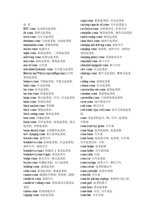
起重EOT crane 电动桥式起重机jib crane 悬臂式起重机truck crane 汽车式起重机abutment crane 台座起重机; 高座起重机ammunition crane 重炮装弹机anchor crane 起锚吊车angle crane 斜座起重机; 三角架起重机antiswing crane 防摆动起重机arm crane 挺杆起重机; 横臂起重机arm of crane 吊车臂articulated hydraulic crane 关节液力起重机Babcok and Wilcox type luffingcrane巴韦型俯仰起重机balance crane 平衡起重机; 平衡式起重机bank crane 岸边起重机bar crane 杆式起重机bar iron crane 铁条起重机barge crane 船式起重机; 浮吊; 浮式起重机beam crane 单梁起重机black-necked crane 黑颈鹤block crane 钢锭起重机block setting crane 钢块起重机boat crane 吊艇起重机boom crane 吊杆起重机; 桁梁起重机; 臂式起重机; 伸臂起重机boom derrick crane 支臂桅杆起重机bow charging crane 船头装货起重机bracket crane 悬臂吊车breakdown crane 拆卸起重机; 应急起重机; 救险吊车; 救险吊车breakdown crane ( 铁路的) 事故起重机breakdown crane wagon 事故起重车bridge crane 桥式吊车; 桥式起重机bucket crane 料罐起重机; 吊斗起重机building crane 建筑起重机cable crane 索道起重机; 缆索起重机camera crane 摄像机升降架; 照相机三脚架cantilever crane 悬臂吊车cantilever walking crane 壁装移动式悬臂起重机canton crane 轻便落地吊车capping crane 加盖起重机cargo crane 船货起重机; 码头起重机carrying capacity of crane 吊车起重能力cast house crane 出铁场吊车; 炉前吊车caterpillar crane 履带起重机; 履带式起重机centre casting crane 铸坑起重机chain block crane 链滑车起重机charging and drawing crane 装卸吊车charging crane 装卸机; 加料吊车; 加料机; 加料起重机charging gantry crane 高架装料吊车clamshell crane 抓斗吊车clamshell equipped crane 抓斗吊车claw crane 爪式起重机climbing crane 爬升式起重机; 攀移式起重机coaling crane 装煤起重机column crane 柱式起重机construction-site crane 建筑起重机container crane 集装箱起重机convertible crane 可更换装备起重机cover crane 地行揭盖吊车crab crane 钳式吊车crab trolley type wall crane 绞车式壁装起重机crane 用起重机起吊; 鹤; 吊车; 起重机;升降架crane (runway) girder 吊车梁crane barge 起重机驳船; 起重机船crane beam 行车梁crane boom 起重机吊架; 起重架; 吊车臂; 吊车起重扒杆; 吊杆crane bridge 起重机桥crane buffer 吊车缓冲器crane cable 吊索crane car 汽车起重机crane carriage 起重小车; 横行小车crane carrier 起重机载运车crane controller 起重控制器crane fall 吊车索crane for placing stoplogs 叠梁闸门起门机crane grab 起重机抓斗crane hoist 移动起重机crane ladle 吊包; 吊车浇包crane link 吊车吊架crane load 吊车起重量; 起重机起重量crane loading 起重机起吊; 起重机装运crane locomotive 起重机车crane magnet 电磁吸盘crane motor 吊车电动机crane output 起重能力crane platform 吊车平台crane radius 起重机起吊半径; 起重机伸臂活动半径; 起重机伸距crane rail 吊车轨crane rating 起重机定额; 起重机载重量crane rope 起重钢绳; 起重机吊索; 吊车钢丝绳crane runner 吊车司机crane runway 起重机走道; 天车滑道crane runway girder 起重机行车大梁crane saver 料垛送进装置crane scale 吊车衡crane shaft 起重机轴crane ship 水上起重机crane stake 起重机柱crane switch 起重机开关crane trolley 起重机行车; 吊机滑车crane trolley wire 起重机接触导线; 行车接触导线crane truck 汽车起重机; 吊车; 车载起重机; 车装起重机; 卡车起重机crane weigher 吊车秤crane wheel 吊车车轮crane winch 起重机绞车crane with double lever jib 四连杆伸臂起重机; 四连杆式伸臂起重机craneage 吊车工时craneman 吊车工; 起重机手; 天车工crane-type loader 起重机式装载机; 转臂式装载机crawler crane 履带吊; 履带起重机; 履带式起重机crawling crane 履带起重机; 履带式起重机crow crane 料耙起重机deck crane 甲板起重机deck twin crane 并列式甲板起重机depiling crane 叠板卸垛吊车de-piling crane 叠板卸垛吊车derrick crane 动臂起重机; 转臂起重机derrick wagon crane 车座人字起重机; 车座人字形起重机derricking jib crane 人字式转臂起重机dividing stationary tower crane 分立固定式塔吊dock crane 码头起重机; 船坞起重机; 造船起重机dogging crane 钳式吊车; 夹钳吊车donkey crane 辅助起重机dove's foot cranesbill 柔毛老鹤草economical gantry crane 简单龙门起重机; 简易龙门起重机electric cater-pillar crane 电动履带起重机electric crane 电动吊车; 电动起重机; 电力起重机electric double-beam bridge crane 电动双梁桥式起重机electric gantry crane 电动龙门式起重机electric jib crane 电动单臂起重机electric locomotive crane 电动机车起重机electric monorail crane 电动单轨起重机electric motor-operated fixed crane 固定式电动起重机electric overhead travelling crane 电动桥式起重机electric single beam crane 电动单梁起重机electric single-beam bridge crane 电动单梁桥式起重机electric slewing crane 电动旋臂起重机electric travel(l)ing crane 电力移动起重机electric travelling crane 电动移动式起重机; 电力移动式起重机electric two-beam bridge crane 电动双梁桥式起重机electric tyre crane 电动轮胎起重机electrical bibeam bridge crane 电动双梁桥式起重机electromagnetic crane 电磁铁起重机electromagnetic disk single-trackcrane电磁盘式单轨吊electromagnetic gantry crane 电磁龙门吊electronic crane scale 电子吊秤erecting crane 装配吊车; 安装用起重机erection crane 安装起重机farm crane 农用起重机fixed boom crane 定臂起重机fixed crane 固定式起重机fixed derrick crane 固定式动臂起重机fixed gantry crane 固定门式起重机; 固定式龙门起重机fixed gauntry crane 固定龙门起重机fixed jib crane 固定式悬臂起重机floating crane 浮动起重机; 浮式起重机; 浮筒起重机; 水上起重机floating crane 浮吊floating crane 浮吊floating jib crane 水上悬臂起重机flying crane helicopter 起重直升机forging crane 锻造起重机foundry slewing crane 翻砂间旋臂起重机full circle crane 全旋转式起重机; 全转式起重机full-rotating crane 全转式起重机gantry crane龙门吊车; 门架吊机; 门式起重机; 轨道吊车; 高架吊车; 高架起重机; 高架移动式起重机gantry crane with man-trolley 带司机小车的龙门起重机gantry crane with shuttle girder 滑伸式龙门起重机gantry crane with slewing man-trolley带司机小车的旋臂龙门起重机gantry transfer crane 门式搬运起重机gasoline crane 汽油起重机geared crane ladle 手摇吊包giant crane 巨型起重机; 巨型起重机gib arm of crane 吊车臂; 吊车起重扒杆gib crane 挺杆起重机goliath crane 巨型起重机; 巨型起重机; 强力起重机; 移动式巨型起重机; 高架起重机gooseneck crane 鹅颈式起重机grab bucket crane 抓斗起重机grab crane 抓岩机吊车grab(bing) crane 抓斗起重机grabbing crane 抓式起重机grapnel travel(l)ing crane 抓斗行走吊车grapnel traveling crane 锚钩式行走起重机grapple equiped crane 锚固式起重机ground-handling crane 地面使用起重机guy derrick crane 牵索人字起重机; 牵索转臂起重机half-gantry crane 单脚高架起重机hammer crane 锤头式起重机hammer crane head 锤式起重机头hammer head crane 锤式起重机hammerhead crane 锤头式起重机hammer-head crane 塔式起重机; 塔式悬臂吊车hammerhead slewing crane 锤头式旋动起重机hand crane 手动起重机hand power track crane 手力移动式起重机hand power travelling crane 手移起重机hand power truck crane 手拉行车hand slewing crane 手旋起重机hand slewing crane ( 小型) 手推旋转起重机hand travelling crane 手移起重机hand wharf crane 手摇码头起重机hand-operated overhang crane 手动单梁桥吊harbour crane 岸上起重机hatch crane 舱口起重机heavy crane 重型吊车heavy duty crane 重级工作制吊车helmet crane 帽形起重机high pedestal jib crane 门座式悬臂起重机high-portal-framed crane 高架门式起重机hoist crane 起重葫芦hoisting crane 升降起重机hook gantry crane 吊钩龙门吊hook type crane 钩式起重机hydraulic crane 水压起重机; 液力起重机; 液压起重机hydraulic gantry crane 液压高架起重机; 水力龙门起重机; 水力桥式起重机hydraulic mobile crane 液压汽车起重机hydraulic slewing crane 液压旋臂起重机;水力旋臂起重机ice can crane 吊冰行车industrial mobile crane 工业用自走式起重机ingot charging crane 铸锭起重机; 钢锭装料吊车ingot crane 钢锭吊车; 钢锭起重机; 吊锭吊车ingot drawing crane 脱锭吊车ingot pit crane 均热炉钳式吊车; 均热炉钳式吊车ingot stripping crane 脱模吊车; 钢锭脱模吊车isolated piller crane 回转起重机jib crane 动臂起重机; 旋臂吊机; 旋臂起重机; 摇臂起重机; 转臂式起重机; 挺杆起重机jib crane charger 回转式吊车加料机jib-boom crane 装配吊车kangaroo crane 带斗式起重机; 袋鼠式起重机ladle crane 铁水包吊车level-luffing crane 鹅头伸臂起重机; 平等运送旋臂起重机; 水平俯仰起重机lever of crane 起重机臂lifting capacity of crane 吊车起重能力; 起重机起重量lifting crane 起重吊车lifting magnet crane 电磁吊车; 电磁吊盘light mast crane 轻型桅杆式转臂起重机loading crane 装料吊车long-boom wharf crane 码头长臂起重机; 码头用长臂起重机lorry loading crane 装车起重机lorry-mounted crane 随车起重机; 起重汽车; 汽车吊; 汽车式起重机low truck crane 车轴式起重机luffing crane 水平起重机; 俯仰式起重机luffing-jib crane 俯仰旋臂起重机magnet chamshell crane 磁力自卸吊车magnet crane 磁力起重机magnet slab turning crane 磁力翻板坯吊车magnetic crane 电磁吊车; 磁力起重机; 磁盘起重机main engine overhauling crane 主机解体检修用吊车make-up crane 配料起重机manifold crane 多用起重机manual crane 手动起重机mast crane 桅杆起重机; 桅式吊机; 柱形塔式起重机material handling crane 运料吊车meadow cranesbill 草原老鹤草mobile automatic manure crane 移动式厩肥自动吊车mobile crane 移动式吊车; 移动式起重机mobile crane ( 常指无轨起重机) 自行吊车mobile hydraulic crane 移动式液压吊车monobox crane 单箱体式起重机; 箱形单梁起重机monorail crane 单轨吊; 单轨起重机monorail crane truck 单轨起重车monostack crane 单轨堆垛起重机movable crane 活动起重机moving bridge crane 移动桥架式起重机; 移动式桥式起重机moving crane 行走吊车non-revolving crane 不可回旋起重机off-highway wheel crane 越野轮式起重机one motor traveling crane 单马达移动吊车one-legged crane 单脚起重机one-motor travel(1)ing crane 单马达吊车ore-loading crane 矿石装卸吊车overhang crane 高架起重机overhead crane 桥式吊车; 高架起重机; 行车overhead grabbing crane 高架抓斗吊车overhead travelling crane with hoist 电动葫芦桥式起重机overhead-travelling crane 高架移动式起重机pendulum crane 摆式吊车pier crane 码头起重机pile driver crane 打桩起重机piling crane 叠板堆垛吊车pillar (rotary, revolving) crane 立柱式旋臂起重机pillar crane 柱式起重机; 塔式起重机pillar jib crane 转柱挺杆起重机pipe-laying crane 铺管机pit crane 翻板坯吊车; 翻坯吊车pivot slewing crane 枢转起重机pivoted jib crane 旋转式悬臂吊车plate crane 板材吊车; 铁板起重机platform crane 台车起重机platform-crane 月台起重机pneumatic crane 风动起重机; 气动吊车polar crane 回转式吊车Polaris-toting crane 波拉瑞氏起重机pontoon crane 平底船起重机; 水上起重机portable cantilever floor crane 轻便悬臂起重机portable crane 轻便起重机; 移动式起重机portable derrick crane 轻便转臂起重机portable floor crane 轻便落地吊车portable slewing crane 轻便转臂起重机portable steam crane 轻便蒸汽起重机portable telescopic crane 轻便伸缩臂式起重机portable yard crane 轻便吊车portal crane 门式起重机portal jib crane 门吊; 门式起重机; 门式旋臂起重机; 龙门吊车post crane 塔柱起重机power crane 动力吊车; 动力起重机; 电动起重机protable slewing crane 轻便旋臂起重机pto driven manure crane 动力输出轴驱动厩肥吊车pyramid crane 角锥架起重机quaternion crane 港口门式起重机quay crane 码头起重机; 码头桥式起重机; 港岸起重机quayside container crane 码头区集装箱起重机rail container crane 集装箱轨道起重机rail crane 轨道起重机rail-mounted crane 轨行起重机rail-mounted overhead crane 轨行高架起重机railway crane 铁路起重机red-crowned crane 仙鹤revolving boom crane 旋转伸臂起重机revolving crane 旋转起重机; 回转起重机revolving disk crane 转盘式起重机revolving mast-type jib crane 定臂转柱起重机revolving pillar jib crane 立柱式旋臂起重机; 回旋立柱臂杆起重机revolving track crane 回转式轨道起重机roof crane 屋顶起重机rope driven travelling crane 钢丝绳移动起重机rotary boom crane 旋转吊杆起重机rotary crane 回转吊车; 回转式起重机; 旋转起重机; 旋转式起重机rotary grab crane 旋转式抓斗起重机rotary tower crane 回转塔式起重机rotating crane 旋转吊车rough-terrain crane 越野起重机rough-terrain wheeled crane 越野轮式起重机rubber tyred gantry crane 轮胎式龙门吊rubbertyred container gantry crane 轮胎式集装箱龙门起重机run about crane 移动式起重机runabout crane 轻便起重机self-propelled crane 自走式起重机; 移动式起重机self-propelled floating revolvingcrane自航回旋浮吊self-propelled gantry manure crane 自走式厩肥高架起重机semi portal crane 单脚高架起重机semi-gantry crane 单脚高架起重机semi-goliath crane 半门式起重机semi-portal bridge crane 半龙门起重机semi-portal crane 半门式起重机; 半门座悬臂起重机; 单柱高架起重机shaft-driven travel(l)ing crane 轴动移动起重机shear leg crane 双腿式起重机; 人字吊臂起重机shear-leg crane 三脚起重机shear-leg derrick crane 合撑式起重机sheet iron crane 铁板起重机shifting crane 移动式起重机shipboard gantry crane 船上桥式吊车ship's crane 船用起重机shop crane 厂用起重机shore crane 岸吊single-beam crane 单轨起重机; 单梁起重机single-beam electric crane 电动单梁起重机single-beam electric hook crane 电动单梁吊钩起重机single-beam travel crane 单梁自行式起重机single-cantilever gantry crane 单悬臂式龙门起重机skip crane 吊斗起重机sky-crane 空中起重机skyline crane 起运机slewing crane 旋臂起重机; 转吊机; 转动起重机; 回臂起重机; 回转式起重机slewing pillar crane 转柱式起重机slow-speed bridge crane 慢速桥式起重机small-flowered cranesbill 小仙鹤草soaking pit crane 夹钳起重机span of crane 起重机臂伸距stack crane 堆装起重机stamp work's crane 碎铁用起重机stationary crane 固定起重机; 固定式起重机stationary slewing crane 定柱旋臂起重机steam crane 蒸汽起重机steam crane (hoist) 蒸汽吊车steam slewing crane 蒸汽旋臂起重机steel beam for crane 吊车钢轨stevedoring crane 装卸起重机stiff-boom crane 固定伸臂起重机stiff-leg derrick crane 定腿式人字起重机stock crane 堆货吊车store crane 仓库起重机straddle carrier crane 跨载起重机straddle crane 跨装起重机straight line crane 直线运动起重机stripper crane 脱模吊车stripper-crane 脱模吊车; 剥片吊车stripping crane 脱锭起重机; 脱模起重机; 剥片吊车strode of crane 起重机起重高度stroke of crane 吊车起重高度studio crane 演播室升降设备swing crane 回转式起重机; 旋臂起重机swing lever crane 旋臂起重机; 旋臂式起重机swinging crane 摇臂吊车; 摇臂起重机swinging pillar jib crane 定柱旋臂起重机tail radius of crane 后部旋转半径; 起重机后部旋转半径tavelling crane 移动起重机teeming crane 浇铸起重机; 浇注起重机telescopic jib crane 伸缩式臂架起重机telpher crane 电动小吊车three-operating crane 三用起重机titan crane 巨型起重机; 巨型起重机tong crane 钳式吊; 钳式吊车tower crane 塔吊; 塔式起重机tower gantry crane 塔式龙门起重机tower jib crane 塔式挺杆起重机tower slewing crane 塔式旋臂起重机towrope crane 缆索起重机track crane 轨道起重机track laying crane 铺轨机track steam crane 轨道蒸汽吊tracklaying crane 铺轨起重机tractor crane 拖拉机起重机transfer crane 运送吊车; 搬运吊车transport crane 运输起重机; 运输用的起重机transporter crane 桁架桥式起重机transshipment crane 转运起重机; 输送起重机traveling bucket crane 移动式抓斗起重机traveling crane 移动式龙门起重机traveling jib crane 移动挺杆起重机traveling luffing crane 移动式俯仰起重机traveling portable jib crane 移动式悬臂吊车traveling tower crane 移动塔式起重机travelling crane 移动式起重机; 起重机行车; 横动起重机travelling forge crane 锻造用移动式起重机travelling gantry crane 移动式龙门吊车travelling portal jib crane 门式移动悬臂起重机traversing crane 桥式吊车trestle crane 高架起重机; 门式起重机tripod crane 三支腿起重机truck crane 轮胎起重机truck with crane 载重汽车附起重机truck-mounted crane 装在汽车上的起重机turning crane 回转式起重机twin hood crane 双钩吊车twin travelling crane 双轮移动起重机twin-lift transporter container crane 双吊式集装箱装卸桥tyre crane 轮胎吊; 轮胎起重机underhung crane 下悬起重机underslung charging crane 悬臂式加料吊车universal crane 全向起重机; 万__________能装卸机vacuum cup crane 真空吸盘式升降机wagon crane 车辆起重机walking crane 步行式吊车; 活动吊车; 执行起重机wall crane 壁装起重机; 壁装式起重机; 墙上起重机; 墙装起重机wall jib crane 旋壁起重机; 旋臂吊车wall sleeving crane 壁行起重机wall slewing crane 墙上旋臂起重机warehouse crane 仓库起重机; 仓库用起重机water crane 水鹤; 水力起重机; 水压起重机water crane arm 水鹤臂water crane column 水鹤柱water crane jib 水鹤臂water crane stand 水鹤柱wharf crane 码头起重机wheel crane 轮式起重机wheeled crane 轮式起重机; 装轮的起重机wheel-mounted crane 轮胎起重机whip crane 动臂起重机whipping crane 摇臂起重机whirler crane 旋臂吊车; 回转式起重机white crane 白鹤with jib crane 带悬臂吊车的龙门起重机with jib crane 带悬臂吊车的龙门起重机with level luffing crane 带俯仰式吊车的龙门起重机with level luffing crane 带俯仰式吊车的龙门起重机with level luffing crane 装有起重杆升降设备的桥式起重机with level luffing crane 装有起重杆升降设备的桥式起重机workshop crane 车间起重机wreck crane 救险起重机; 救险起重机; 救援吊车; 救援吊车yard crane 移动起重机; 场地起重机; 场内起重机; 堆场吊机yard-crane 移动吊车abutment crane 台座起重机; 高座起重机ammunition crane 重炮装弹机crane ladle 吊包; 吊车浇包crane link 吊车吊架crane load 吊车起重量; 起重机起重量crane loading 起重机起吊; 起重机装运crane locomotive 起重机车crane magnet 电磁吸盘crane motor 吊车电动机crane output 起重能力crane platform 吊车平台crane radius 起重机起吊半径; 起重机伸臂活动半径; 起重机伸距crane rail 吊车轨crane rating 起重机定额; 起重机载重量crane rope 起重钢绳; 起重机吊索; 吊车钢丝绳crane runner 吊车司机crane runway 起重机走道; 天车滑道crane runway girder 起重机行车大梁crane saver 料垛送进装置crane scale 吊车衡crane shaft 起重机轴crane ship 水上起重机crane stake 起重机柱crane switch 起重机开关crane trolley 起重机行车; 吊机滑车crane trolley wire 起重机接触导线; 行车接触导线crane truck 汽车起重机; 吊车; 车载起重机; 车装起重机; 卡车起重机crane weigher 吊车秤crane wheel 吊车车轮crane winch 起重机绞车crane with double lever jib 四连杆伸臂起重机; 四连杆式伸臂起重机crane-type loader 起重机式装载机; 转臂式装载机craneage 吊车工时craneman 吊车工; 起重机手; 天车工crawler crane 履带吊; 履带起重机; 履带式起重机crawling crane 履带起重机; 履带式起重机crow crane 料耙起重机de-piling crane 叠板卸垛吊车deck crane 甲板起重机deck twin crane 并列式甲板起重机depiling crane 叠板卸垛吊车derrick crane 动臂起重机; 转臂起重机derrick wagon crane 车座人字起重机; 车座人字形起重机derricking jib crane 人字式转臂起重机dividing stationary tower crane 分立固定式塔吊dock crane 码头起重机; 船坞起重机; 造船起重机dogging crane 钳式吊车; 夹钳吊车donkey crane 辅助起重机dove's foot cranesbill 柔毛老鹤草economical gantry crane 简单龙门起重机; 简易龙门起重机electric cater-pillar crane 电动履带起重机electric crane 电动吊车; 电动起重机; 电力起重机electric double-beam bridge crane 电动双梁桥式起重机electric gantry crane 电动龙门式起重机electric jib crane 电动单臂起重机electric locomotive crane 电动机车起重机electric monorail crane 电动单轨起重机electric motor-operated fixed crane 固定式电动起重机electric overhead travelling crane 电动桥式起重机electric s ingle beam crane 电动单梁起重机electric s ingle-beam bridge crane 电动单梁桥式起重机electric s lewing crane 电动旋臂起重机electric travel(l)ing crane 电力移动起重机electric travelling crane 电动移动式起重机; 电力移动式起重机electric two-beam bridge crane 电动双梁桥式起重机electric tyre crane 电动轮胎起重机electrical bibeam bridge crane 电动双梁桥式起重机(EOT crane) 电动桥式起重机(EOT crane) 电动桥式起重机electromagnetic crane 电磁铁起重机electromagnetic disk single-track crane 电磁盘式单轨吊electromagnetic gantry crane 电磁龙门吊electronic crane scale 电子吊秤erecting crane 装配吊车; 安装用起重机erection crane 安装起重机farm crane 农用起重机fixed boom crane 定臂起重机fixed crane 固定式起重机fixed derrick crane 固定式动臂起重机fixed gantry crane 固定门式起重机; 固定式龙门起重机fixed gauntry crane 固定龙门起重机fixed jib crane 固定式悬臂起重机floating crane 浮动起重机; 浮式起重机; 浮筒起重机; 水上起重机floating jib crane 水上悬臂起重机flying crane helicopter 起重直升机forging crane 锻造起重机foundry slewing crane 翻砂间旋臂起重机full circle crane 全旋转式起重机; 全转式起重机full-rotating crane 全转式起重机gantry crane 龙门吊车; 门架吊机; 门式起重机; 轨道吊车; 高架吊车; 高架起重机; 高架移动式起重机with jib crane 带悬臂吊车的龙门起重机with jib crane 带悬臂吊车的龙门起重机with level luffing crane 带俯仰式吊车的龙门起重机with level luffing crane 带俯仰式吊车的龙门起重机gantry crane with man-trolley 带司机小车的龙门起重机gantry crane with shuttle girder 滑伸式龙门起重机gantry crane with slewing man-trolley 带司机小车的旋臂龙门起重机gantry transfer crane 门式搬运起重机gasoline crane 汽油起重机geared crane ladle 手摇吊包giant crane 巨型起重机; 巨型起重机gib arm of crane 吊车臂; 吊车起重扒杆gib crane 挺杆起重机goliath crane 巨型起重机; 巨型起重机; 强力起重机; 移动式巨型起重机; 高架起重机gooseneck crane 鹅颈式起重机grab bucket crane 抓斗起重机grab crane 抓岩机吊车grab(bing) crane 抓斗起重机grabbing crane 抓式起重机grapnel travel(l)ing crane 抓斗行走吊车grapnel traveling crane 锚钩式行走起重机grapple equiped crane 锚固式起重机ground-handling crane 地面使用起重机guy derrick crane 牵索人字起重机; 牵索转臂起重机half-gantry crane 单脚高架起重机hammer crane 锤头式起重机hammer crane head 锤式起重机头hammer head crane 锤式起重机hammer-head crane 塔式起重机; 塔式悬臂吊车hammerhead crane 锤头式起重机hammerhead slewing crane 锤头式旋动起重机hand crane 手动起重机hand power track crane 手力移动式起重机hand power travelling crane 手移起重机hand power truck crane 手拉行车hand slewing crane 手旋起重机hand slewing crane (小型) 手推旋转起重机hand travelling crane 手移起重机hand wharf crane 手摇码头起重机hand-operated overhang crane 手动单梁桥吊harbour crane 岸上起重机hatch crane 舱口起重机heavy crane 重型吊车heavy duty crane 重级工作制吊车helmet crane 帽形起重机high pedestal jib crane 门座式悬臂起重机high-portal-framed crane 高架门式起重机hoist crane 起重葫芦hoisting crane 升降起重机hook gantry crane 吊钩龙门吊hook type crane 钩式起重机hydraulic crane 水压起重机; 液力起重机; 液压起重机hydraulic gantry crane 液压高架起重机; 水力龙门起重机; 水力桥式起重机hydraulic mobile crane 液压汽车起重机hydraulic slewing crane 液压旋臂起重机; 水力旋臂起重机ice can crane 吊冰行车industrial mobile crane 工业用自走式起重机ingot charging crane 铸锭起重机; 钢锭装料吊车ingot crane 钢锭吊车; 钢锭起重机; 吊锭吊车ingot drawing crane 脱锭吊车ingot pit crane 均热炉钳式吊车; 均热炉钳式吊车ingot stripping crane 脱模吊车; 钢锭脱模吊车isolated piller crane 回转起重机jib crane 动臂起重机; 旋臂吊机; 旋臂起重机; 摇臂起重机; 转臂式起重机; 挺杆起重机jib crane charger 回转式吊车加料机jib-boom crane 装配吊车kangaroo crane 带斗式起重机; 袋鼠式起重机ladle crane 铁水包吊车level-luffing crane 鹅头伸臂起重机; 平等运送旋臂起重机; 水平俯仰起重机lever of crane 起重机臂lifting capacity of crane 吊车起重能力; 起重机起重量lifting crane 起重吊车lifting magnet crane 电磁吊车; 电磁吊盘light mast crane 轻型桅杆式转臂起重机loading crane 装料吊车long-boom wharf crane 码头长臂起重机; 码头用长臂起重机lorry loading crane 装车起重机lorry-mounted crane 随车起重机; 起重汽车; 汽车吊; 汽车式起重机low truck crane 车轴式起重机luffing crane 水平起重机; 俯仰式起重机luffing-jib crane 俯仰旋臂起重机magnet chamshell crane 磁力自卸吊车magnet crane 磁力起重机magnet slab turning crane 磁力翻板坯吊车magnetic crane 电磁吊车; 磁力起重机; 磁盘起重机main engine overhauling crane 主机解体检修用吊车make-up crane 配料起重机manifold crane 多用起重机manual crane 手动起重机mast crane 桅杆起重机; 桅式吊机; 柱形塔式起重机material handling crane 运料吊车meadow cranesbill 草原老鹤草mobile automatic manure crane 移动式厩肥自动吊车mobile crane 移动式吊车; 移动式起重机mobile crane (常指无轨起重机) 自行吊车mobile hydraulic crane 移动式液压吊车monobox crane 单箱体式起重机; 箱形单梁起重机monorail crane 单轨吊; 单轨起重机monorail crane truck 单轨起重车monostack crane 单轨堆垛起重机movable crane 活动起重机moving bridge crane 移动桥架式起重机; 移动式桥式起重机moving crane 行走吊车non-revolving crane 不可回旋起重机off-highway wheel crane 越野轮式起重机one motor traveling crane 单马达移动吊车one-legged crane 单脚起重机one-motor travel(1)ing crane 单马达吊车ore-loading crane 矿石装卸吊车overhang crane 高架起重机overhead crane 桥式吊车; 高架起重机; 行车overhead grabbing crane 高架抓斗吊车overhead travelling crane with hoist 电动葫芦桥式起重机overhead-travelling crane 高架移动式起重机pendulum crane 摆式吊车pier crane 码头起重机pile driver crane 打桩起重机piling crane 叠板堆垛吊车pillar (rotary, revolving) crane 立柱式旋臂起重机pillar crane 柱式起重机; 塔式起重机pillar jib crane 转柱挺杆起重机pipe-laying crane 铺管机pit crane 翻板坯吊车; 翻坯吊车pivot slewing crane 枢转起重机pivoted jib crane 旋转式悬臂吊车plate crane 板材吊车; 铁板起重机platform crane 台车起重机platform-crane 月台起重机pneumatic crane 风动起重机; 气动吊车polar crane 回转式吊车Polaris-toting crane 波拉瑞氏起重机pontoon crane 平底船起重机; 水上起重机floating crane 浮吊floating crane 浮吊portable cantilever floor crane 轻便悬臂起重机portable crane 轻便起重机; 移动式起重机portable derrick crane 轻便转臂起重机portable floor crane 轻便落地吊车portable slewing crane 轻便转臂起重机portable steam crane 轻便蒸汽起重机portable telescopic crane 轻便伸缩臂式起重机portable yard crane 轻便吊车portal crane 门式起重机portal jib crane 门吊; 门式起重机; 门式旋臂起重机; 龙门吊车post crane 塔柱起重机power crane 动力吊车; 动力起重机; 电动起重机protable slewing crane 轻便旋臂起重机pto driven manure crane 动力输出轴驱动厩肥吊车pyramid crane 角锥架起重机quaternion crane 港口门式起重机quay crane 码头起重机; 码头桥式起重机; 港岸起重机quayside container crane 码头区集装箱起重机rail container crane 集装箱轨道起重机rail crane 轨道起重机rail-mounted crane 轨行起重机rail-mounted overhead crane 轨行高架起重机railway crane 铁路起重机red-crowned crane 仙鹤revolving boom crane 旋转伸臂起重机revolving crane 旋转起重机; 回转起重机revolving disk crane 转盘式起重机revolving mast-type jib crane 定臂转柱起重机revolving pillar jib crane 立柱式旋臂起重机; 回旋立柱臂杆起重机revolving track crane 回转式轨道起重机roof crane 屋顶起重机rope driven travelling crane 钢丝绳移动起重机rotary boom crane 旋转吊杆起重机rotary crane 回转吊车; 回转式起重机; 旋转起重机; 旋转式起重机rotary grab crane 旋转式抓斗起重机rotary tower crane 回转塔式起重机rotating crane 旋转吊车rough-terrain crane 越野起重机rough-terrain wheeled crane 越野轮式起重机rubber tyred gantry crane 轮胎式龙门吊rubbertyred container gantry crane 轮胎式集装箱龙门起重机run about crane 移动式起重机runabout crane 轻便起重机self-propelled crane 自走式起重机; 移动式起重机self-propelled floating revolving crane 自航回旋浮吊self-propelled gantry manure crane 自走式厩肥高架起重机semi portal crane 单脚高架起重机semi-gantry crane 单脚高架起重机semi-goliath crane 半门式起重机semi-portal bridge crane 半龙门起重机semi-portal crane 半门式起重机; 半门座悬臂起重机; 单柱高架起重机shaft-driven travel(l)ing crane 轴动移动起重机shear leg crane 双腿式起重机; 人字吊臂起重机shear-leg crane 三脚起重机shear-leg derrick crane 合撑式起重机sheet iron crane 铁板起重机。

Portal crane structure and working principle Portal crane is a metal structure, the four major agencies and the three major components of the overall system. Figure 1-1 for the M10-25 portal crane, its metal structure: a boom system, Renzi Jia 4, Room 6, dial 7, 8, in turn, door-9, 10 ladder platform, cab 14. Four bodies have: Change bodies 2, operating 12 agencies, or organisations from 15, 16 and the rotary mechanism for the completion of cross pieces of action which the hydraulic system 3.Three systems: the power supply to the control panel 21, Resistance Box 22; manipulation used to manipulate the drivers seat 20; used for security and anti-overload limiter 5 to 19 devices. In addition, for ease of manipulation and grab 18 set grab stabilizer 17, and cable volumes SR ll, 13, and other support under. These components to work together to complete the lifting of goods and transport operations.1. Lifting bodies图:1—1In order to facilitate the transition to double-rope grab bulk cargo handling, general portal cranes from the double-reel or body, the two motors were driven by their respective reducer, a slowdown after three output and promote their respective volumes of wire rope SR. Or from one end of rope to a fixed volume in Brief, Renzi Jia on the other end through the pulley and compensation as the two ends of the bridge of the nose of the pulley, and then fixed on the hook or grab.2. Change agenciesThe portal crane Change often there are several forms of transmission, the transmission line as:(1) fan-shaped gear drive a motor reducer a Change Change gear ofa small fan-shaped gear of a tension bar, so that the main par Movement (Change);(2) Change screw and nut drive a motor reducer a Change Change Change screw a nut, so that the main par Movement (Change)图:1—2(3) gear, rack Change Change Change rack ofa small gear, the main leader movement (Change);(4) Change hydraulic transmission of a hydraulic pump motor fuel tank of a variation of a connecting rod. At the main Movement (Change).In order to improve the efficiency of cranes and better meet operational requirements, using a portal crane working Change body, the band set range. Change the characteristics of this work is the number of frequent, varying resistance larger and higher speed range. And then, if only a simple swing crane boom Change the way, it will cause the focus of Boom, by the admission of devices and mobile hanging in the level of the sport at the same time have a take-off and landing, in Figure 1-2. When the boom of a change in perspective α, by the hanging of a certain distance from Mobile, but also improve the hanging of a certain height h.This makes drive in the Change process, in addition to general must overcome the resistance, it is also necessary to overcome because of boom and hanging themselves lifting heavy objects caused by resistance, not only to increase power-driven, but also an increase of drivers operating location Difficulties. To this end, it was designed Boom lifting weights and balance system of compensation device. Boom balance system is the role of the boom system in the center of Change does not occur in the course of movements; lifting weights compensation device that is the role of weight in the process of variation along the track of moving closer to level.In the portal crane, the compensation devices are generally twomethods: the compensation law and the composition of the rope Boom Compensation Act.(1) the rope's Compensation ActIn lifting the rope pulley system to introduce compensation group, in Figure 1-3. - Oriented arm of a crane and pulley A rotation of the stent on the pulley B, composed of compensation-pulley blocks. When set up or arm, the arm-pulley A 0 A along with a radius of the arc for the movement to A ', at this time, rehabilitation pulley group the distance between the two pulley around. By choosing the appropriate size and pulley group rate, we can release to the pulley group of the rope, to compensate for the higher end of the crane, so that heavy objects along the approximate level of mobile line.(2) portfolio Boom Compensation Act① This is a special type of split-hinged combination to achieve compensation purposes, figure 1-4 is one of the form. 2 as the bridge of the nose with a hinged Boom, Lasheng 3 fixed to the trunk beam, the other end connected to the crane rotating platform on the framework. Change, as the bridge of the nose due to swing, Lasheng point of contact with their position that is changing, which is equivalent to the diagram of a quadrilateral hinged side in the event of a change. If appropriate choice quadrilateral side of the ratio, you can achieve when heavy objects can range along the approximate level of mobile line.At present, China's production of the portal cranes are even Qian compensation to the four institutions.图:1—3 图:1—4 图1—5② plans for the 1-5 combination Boom Compensation Act of another form, it is also unchanged from a number length of the rigid bar. The system is also a feature of the campaign plane with four Qian agencies. It is also the split-swing, as a bridge of the nose to the endpoint in a certain range of movement for close to the horizon, such reached weights in the range of movement when the purpose.3. Rotating bodiesFrom one or two rotating torque motor output of the worm reducer or gearreducer slowdown, driven rotary small gear, the gear to promote small fixed on the rotating column to the ring gear, so that the upper portal crane Rotation, to complete their tasks.4. Run institutionsBy two or four walking by their respective torque motor output slowdown after the reducer, transmission gear to open group, and then drive round the door Walking along the track of movement to achieve the door for the purpose of changing jobs. It can also be used for loading and unloading of cargoes walk. The portal crane lifting, rotating, varying the three institutions can work alone or joint operations, to complete the necessary work content.门座式起重机构造与工作原理门座式起重机是由金属结构、四大机构和三大系统组成的整体。
The History of Crane1.OverviewThe first construction cranes were invented by the Ancient Greeks and were powered by men or beasts of burden, such as donkeys. These cranes were used for the construction of tall buildings. Larger cranes were later developed, employing the use of human treadwheels, permitting the lifting of heavier weights. In the High Middle Ages, harbor cranes were introduced to load and unload ships and assist with their construction – some were built into stone towers for extra strength and stability. The earliest cranes were constructed from wood, but cast iron and steel took over with the coming of the Industrial Revolution.For many centuries, power was supplied by the physical exertion of men or animals, although hoists in watermills and windmills could be driven by the harnessed natural power. The first 'mechanical' power was provided by steam engines, the earliest steam crane being introduced in the 18th or 19th century, with many remaining in use well into the late 20th century. Modern cranes usually use internal combustion engines or electric motors and hydraulic systems to provide a much greater lifting capability than was previously possible, although manual cranes are still utilized where the provision of power would be uneconomic.Cranes exist in an enormous variety of forms – each tailored to a specific use. Sizes range from the smallest jib cranes, used inside workshops, to the tallest tower cranes, used for constructing high buildings. For a while, mini - cranes are also used for constructing high buildings, in order to facilitate constructions by reaching tight spaces. Finally, we can find larger floating cranes, generally used to build oil rigs and salvage sunken ships. This article also covers lifting machines that do not strictly fit the above definition of a crane, but are generally known as cranes, such as stacker cranes and loader cranes.2. History(1)Ancient GreeceThe crane for lifting heavy loads was invented by the Ancient Greeks in the late 6th century BC. The archaeological record shows that no later than c.515 BC distinctive cuttings for both lifting tongs and lewis irons begin to appear on stone blocks of Greek temples. Since these holes point at the use of a lifting device, and since they are to be found either above the center of gravity of the block, or in pairs equidistant from a point over the center of gravity, they are regarded by archaeologists as the positive evidence required for the existence of the crane.The introduction of the winch and pulley hoist soon lead to a widespread replacement of ramps as the main means of vertical motion. For the next two hundred years, Greek building sites witnessed a sharp drop in the weights handled, as the new lifting technique made the use of several smaller stones more practical than of fewer larger ones. In contrast to the archaic period with its tendency to ever-increasing block sizes, Greek temples of the classical age like the Parthenon invariably featured stone blocks weighing less than 15-20 tons. Also, the practice of erecting large monolithic columns was practically abandoned in favor of using several column drums.Although the exact circumstances of the shift from the ramp to the crane technology remain unclear, it has been argued that the volatile social and political conditions of Greece were moresuitable to the employment of small, professional construction teams than of large bodies of unskilled labor, making the crane more preferable to the Greek polis than the more labor-intensive ramp which had been the norm in the autocratic societies of Egypt or Assyria.The first unequivocal literary evidence for the existence of the compound pulley system appears in the Mechanical Problems (Mech. 18, 853a32-853b13) attributed to Aristotle (384-322 BC), but perhaps composed at a slightly later date. Around the same time, block sizes at Greek temples began to match their archaic predecessors again, indicating that the more sophisticated compound pulley must have found its way to Greek construction sites by then.Ancient RomeThe heyday of the crane in ancient times came during the Roman Empire, when construction activity soared and buildings reached enormous dimensions. The Romans adopted the Greek crane and developed it further. We are relatively well informed about their lifting techniques, thanks to rather lengthy accounts by the engineers Vitruvius (De Architectura 10.2, 1-10) and Heron of Alexandria (Mechanica 3.2-5). There are also two surviving reliefs of Roman treadwheel cranes, with the Haterii tombstone from the late first century AD being particularly detailed.The simplest Roman crane, the Trispastos, consisted of a single-beam jib, a winch, a rope, and a block containing three pulleys. Having thus a mechanical advantage of 3:1, it has been calculated that a single man working the winch could raise 150 kg (3 pulleys x 50 kg = 150), assuming that 50 kg represent the maximum effort a man can exert over a longer time period. Heavier crane types featured five pulleys (Pentaspastos) or, in case of the largest one, a set of three by five pulleys (Polyspastos) and came with two, three or four masts, depending on the maximum load. The Polyspastos, when worked by four men at both sides of the winch, could already lift 3000 kg (3 ropes x 5 pulleys x 4 men x 50 kg = 3000 kg). In case the winch was replaced by a treadwheel, the maximum load even doubled to 6000 kg at only half the crew, since the treadwheel possesses a much bigger mechanical advantage due to its larger diameter. This meant that, in comparison to the construction of the Egyptian Pyramids, where about 50 men were needed to move a 2.5 ton stone block up the ramp (50 kg per person), the lifting capability of the Roman Polyspastos proved to be 60 times higher (3000 kg per person).However, numerous extant Roman buildings which feature much heavier stone blocks than those handled by the Polyspastos indicate that the overall lifting capability of the Romans went far beyond that of any single crane. At the temple of Jupiter at Baalbek, for instance, the architrave blocks weigh up to 60 tons each, and one corner cornice block even over 100 tons, all of them raised to a height of about 19 m. In Rome, the capital block of Trajan's Column weighs 53.3 tons, which had to be lifted to a height of about 34 m (see construction of Trajan's Column).It is assumed that Roman engineers lifted these extraordinary weights by two measures (see picture below for comparable Renaissance technique): First, as suggested by Heron, a lifting tower was set up, whose four masts were arranged in the shape of a quadrangle with parallel sides, not unlike a siege tower, but with the column in the middle of the structure (Mechanica 3.5). Second, a multitude of capstans were placed on the ground around the tower, for, although having a lower leverage ratio than treadwheels, capstans could be set up in higher numbers and run by more men (and, moreover, by draught animals). This use of multiple capstans is also described by AmmianusMarcellinus (17.4.15) in connection with the lifting of the Lateranense obelisk in the Circus Maximus (ca. 357 AD). The maximum lifting capability of a single capstan can be established by the number of lewis iron holes bored into the monolith. In case of the Baalbek architrave blocks, which weigh between 55 and 60 tons, eight extant holes suggest an allowance of 7.5 ton per lewis iron, that is per capstan. Lifting such heavy weights in a concerted action required a great amount of coordination between the work groups applying the force to the capstans.Middle AgesDuring the High Middle Ages, the treadwheel crane was reintroduced on a large scale after the technology had fallen into disuse in western Europe with the demise of the Western Roman Empire. The earliest reference to a treadwheel (magna rota) reappears in archival literature in France about 1225, followed by an illuminated depiction in a manuscript of probably also French origin dating to 1240. In navigation, the earliest uses of harbor cranes are documented for Utrecht in 1244, Antwerp in 1263, Brugge in 1288 and Hamburg in 1291, while in England the treadwheel is not recorded before 1331.Generally, vertical transport could be done more safely and inexpensively by cranes than by customary methods. Typical areas of application were harbors, mines, and, in particular, building sites where the treadwheel crane played a pivotal role in the construction of the lofty Gothic cathedrals. Nevertheless, both archival and pictorial sources of the time suggest that newly introduced machines like treadwheels or wheelbarrows did not completely replace more labor-intensive methods like ladders, hods and handbarrows. Rather, old and new machinery continued to coexist on medieval construction sites and harbors.Apart from treadwheels, medieval depictions also show cranes to be powered manually by windlasses with radiating spokes, cranks and by the 15th century also by windlasses shaped like a ship's wheel. To smooth out irregularities of impulse and get over 'dead-spots' in the lifting process flywheels are known to be in use as early as 1123.The exact process by which the treadwheel crane was reintroduced is not recorded, although its return to construction sites has undoubtedly to be viewed in close connection with the simultaneous rise of Gothic architecture. The reappearance of the treadwheel crane may have resulted from a technological development of the windlass from which the treadwheel structurally and mechanically evolved. Alternatively, the medieval treadwheel may represent a deliberate reinvention of its Roman counterpart drawn from Vitruvius' De architectura which was available in many monastic libraries. Its reintroduction may have been inspired, as well, by the observation of the labor-saving qualities of the waterwheel with which early treadwheels shared many structural similarities.Structure and placementThe medieval treadwheel was a large wooden wheel turning around a central shaft with a treadway wide enough for two workers walking side by side. While the earlier 'compass-arm' wheel had spokes directly driven into the central shaft, the more advanced 'clasp-arm' type featured arms arranged as chords to the wheel rim, giving the possibility of using a thinner shaft and providing thus a greater mechanical advantage.Contrary to a popularly held belief, cranes on medieval building sites were neither placed on the extremely lightweight scaffolding used at the time nor on the thin walls of the Gothic churches which were incapable of supporting the weight of both hoisting machine and load. Rather, cranes were placed in the initial stages of construction on the ground, often within the building. When a new floor was completed, and massive tie beams of the roof connected the walls, the crane was dismantled and reassembled on the roof beams from where it was moved from bay to bay during construction of the vaults. Thus, the crane ‘grew’ and ‘wandered’ with the building with the result that today all extant construction cranes in England are found in church towers above the vaulting and below the roof, where they remained after building construction for bringing material for repairs aloft.Less frequently, medieval illuminations also show cranes mounted on the outside of walls with the stand of the machine secured to putlogs.Mechanics and operationIn contrast to modern cranes, medieval cranes and hoists - much like their counterparts in Greece and Rome - were primarily capable of a vertical lift, and not used to move loads for a considerable distance horizontally as well. Accordingly, lifting work was organized at the workplace in a different way than today. In building construction, for example, it is assumed that the crane lifted the stone blocks either from the bottom directly into place, or from a place opposite the centre of the wall from where it could deliver the blocks for two teams working at each end of the wall. Additionally, the crane master who usually gave orders at the treadwheel workers from outside the crane was able to manipulate the movement laterally by a small rope attached to the load. Slewing cranes which allowed a rotation of the load and were thus particularly suited for dockside work appeared as early as 1340. While ashlar blocks were directly lifted by sling, lewis or devil's clamp (German Teufelskralle), other objects were placed before in containers like pallets, baskets, wooden boxes or barrels.It is noteworthy that medieval cranes rarely featured ratchets or brakes to forestall the load from running backward. This curious absence is explained by the high friction force exercised by medieval treadwheels which normally prevented the wheel from accelerating beyond control. Harbor usageAccording to the "present state of knowledge" unknown in antiquity, stationary harbor cranes are considered a new development of the Middle Ages. The typical harbor crane was a pivoting structure equipped with double treadwheels. These cranes were placed docksides for the loading and unloading of cargo where they replaced or complemented older lifting methods like see-saws, winches and yards.Two different types of harbor cranes can be identified with a varying geographical distribution: While gantry cranes which pivoted on a central vertical axle were commonly found at the Flemish and Dutch coastside, German sea and inland harbors typically featured tower cranes where the windlass and treadwheels were situated in a solid tower with only jib arm and roof rotating. Interestingly, dockside cranes were not adopted in the Mediterranean region and the highly developed Italian ports where authorities continued to rely on the more labor-intensive method ofunloading goods by ramps beyond the Middle Ages.Unlike construction cranes where the work speed was determined by the relatively slow progress of the masons, harbor cranes usually featured double treadwheels to speed up loading. The two treadwheels whose diameter is estimated to be 4 m or larger were attached to each side of the axle and rotated together. Today, according to one survey, fifteen treadwheel harbor cranes from pre-industrial times are still extant throughout Europe.[28] Beside these stationary cranes, floating cranes which could be flexibly deployed in the whole port basin came into use by the 14th century.RenaissanceA lifting tower similar to that of the ancient Romans was used to great effect by the Renaissance architect Domenico Fontana in 1586 to relocate the 361 t heavy Vatican obelisk in Rome. From his report, it becomes obvious that the coordination of the lift between the various pulling teams required a considerable amount of concentration and discipline, since, if the force was not applied evenly, the excessive stress on the ropes would make them rupture.Early modern ageCranes were used domestically in the 17th and 18th century. The chimney or fireplace crane was used to swing pots and kettles over the fire and the height was adjusted by a trammel.4. Types of the cranesMobileMain article: Mobile craneThe most basic type of mobile crane consists of a truss or telescopic boom mounted on a mobile platform - be it on road, rail or water.FixedExchanging mobility for the ability to carry greater loads and reach greater heights due to increased stability, these types of cranes are characterized that they, or at least their main structure does not move during the period of use. However, many can still be assembled and disassembled.外文翻译起重机的历史1. 概况第一台具有机械结构的起重机是由古希腊人发明的,并且由人或者是牲畜比如驴,作为动力源。
The History of Crane1. OverviewThe first construction cranes were invented by the Ancient Greeks and were powered by men or beasts of burden, such as donkeys. These cranes were used for the construction of tall buildings. Larger cranes were later developed, employing the use of human treadwheels, permitting the lifting of heavier weights. In the High Middle Ages, harbor cranes were introducedto load and unload ships and assist with their construction – some were built into stone towers for extra strength and stability. The earliest cranes were constructed from wood, but cast iron and steel took over with the coming of the Industrial Revolution.For many centuries, power was supplied by the physical exertion of men or animals, although hoists in watermills and windmills could be driven by the harnessed natural power. The first 'mechanical' power was provided by steam engines, the earliest steam crane being introducedin the 18th or 19th century, with many remaining in use well into the late 20th century. Modern cranes usually use internal combustion engines or electric motors and hydraulic systems to provide a much greater lifting capability than was previously possible, although manual cranes are still utilized where the provision of power would be uneconomic.Cranes exist in an enormous variety of forms – each tailored to a specific use. Sizes range from the smallest jib cranes, used inside workshops, to the tallest tower cranes, used for constructing high buildings. For a while, mini - cranes are also used for constructing high buildings, in order to facilitate constructions by reaching tight spaces. Finally, we can find larger floating cranes, generally used to build oil rigs and salvage sunken ships. This article also covers lifting machines that do not strictly fit the above definition of a crane, but are generally known as cranes, such as stacker cranes and loader cranes.2. History(1)Ancient GreeceThe crane for lifting heavy loads was invented by the Ancient Greeks in the late 6th century BC. The archaeological record shows that no later than c.515 BC distinctive cuttings for both lifting tongs and lewis irons begin to appear on stone blocks of Greek temples. Since these holes point at the use of a lifting device, and since they are to be found either above the center of gravity of the block, or in pairs equidistant from a point over the center of gravity, they are regarded by archaeologists as the positive evidence required for the existence of the crane.The introduction of the winch and pulley hoist soon lead to a widespread replacement of ramps as the main means of vertical motion. For the next two hundred years, Greek building sites witnesseda sharp drop in the weights handled, as the new lifting technique made the use of several smaller stones more practical than of fewer larger ones. In contrast to the archaic period with its tendencyto ever-increasing block sizes, Greek temples of the classical age like the Parthenon invariably featured stone blocks weighing less than 15-20 tons. Also, the practice of erecting large monolithic columns was practically abandoned in favor of using several column drums.Although the exact circumstances of the shift from the ramp to the crane technology remain unclear, it has been argued that the volatile social and political conditions of Greece were moresuitable to the employment of small, professional construction teams than of large bodies of unskilled labor, making the crane more preferable to the Greek polis than the more labor-intensive ramp which had been the norm in the autocratic societies of Egypt or Assyria.The first unequivocal literary evidence for the existence of the compound pulley system appears in the Mechanical Problems (Mech. 18, 853a32-853b13) attributed to Aristotle (384-322 BC), but perhaps composed at a slightly later date. Around the same time, block sizes at Greek temples began to match their archaic predecessors again, indicating that the more sophisticated compound pulley must have found its way to Greek construction sites by then.Ancient RomeThe heyday of the crane in ancient times came during the Roman Empire, when construction activity soared and buildings reached enormous dimensions. The Romans adopted the Greek crane and developed it further. We are relatively well informed about their lifting techniques, thanks to rather lengthy accounts by the engineers Vitruvius (De Architectura 10.2, 1-10) and Heron of Alexandria (Mechanica 3.2-5). There are also two surviving reliefs of Roman treadwheel cranes, with the Haterii tombstone from the late first century AD being particularly detailed.The simplest Roman crane, the Trispastos, consisted of a single-beam jib, a winch, a rope, and a block containing three pulleys. Having thus a mechanical advantage of 3:1, it has been calculated that a single man working the winch could raise 150 kg (3 pulleys x 50 kg = 150), assuming that 50 kg represent the maximum effort a man can exert over a longer time period. Heavier crane types featured five pulleys (Pentaspastos) or, in case of the largest one, a set of three by five pulleys (Polyspastos) and came with two, three or four masts, depending on the maximum load. The Polyspastos, when worked by four men at both sides of the winch, could already lift 3000 kg (3 ropes x 5 pulleys x 4 men x 50 kg = 3000 kg). In case the winch was replaced by a treadwheel, the maximum load even doubled to 6000 kg at only half the crew, since the treadwheel possesses a much bigger mechanical advantage due to its larger diameter. This meant that, in comparison to the construction of the Egyptian Pyramids, where about 50 men were needed to move a 2.5 ton stone block up the ramp (50 kg per person), the lifting capability of the Roman Polyspastos proved to be 60 times higher (3000 kg per person).However, numerous extant Roman buildings which feature much heavier stone blocks than those handled by the Polyspastos indicate that the overall lifting capability of the Romans went far beyond that of any single crane. At the temple of Jupiter at Baalbek, for instance, the architrave blocks weigh up to 60 tons each, and one corner cornice block even over 100 tons, all of them raised to a height of about 19 m. In Rome, the capital block of Trajan's Column weighs 53.3 tons, which had to be lifted to a height of about 34 m (see construction of Trajan's Column).It is assumed that Roman engineers lifted these extraordinary weights by two measures (see picture below for comparable Renaissance technique): First, as suggested by Heron, a lifting tower was set up, whose four masts were arranged in the shape of a quadrangle with parallel sides, not unlike a siege tower, but with the column in the middle of the structure (Mechanica 3.5). Second, a multitude of capstans were placed on the ground around the tower, for, although having a lower leverage ratio than treadwheels, capstans could be set up in higher numbers and run by more men (and, moreover, by draught animals). This use of multiple capstans is also described by AmmianusMarcellinus (17.4.15) in connection with the lifting of the Lateranense obelisk in the Circus Maximus (ca. 357 AD). The maximum lifting capability of a single capstan can be established by the number of lewis iron holes bored into the monolith. In case of the Baalbek architrave blocks, which weigh between 55 and 60 tons, eight extant holes suggest an allowance of 7.5 ton per lewis iron, that is per capstan. Lifting such heavy weights in a concerted action required a great amount of coordination between the work groups applying the force to the capstans.Middle AgesDuring the High Middle Ages, the treadwheel crane was reintroduced on a large scale after the technology had fallen into disuse in western Europe with the demise of the Western Roman Empire. The earliest reference to a treadwheel (magna rota) reappears in archival literature in France about 1225, followed by an illuminated depiction in a manuscript of probably also French origin dating to 1240. In navigation, the earliest uses of harbor cranes are documented for Utrecht in 1244, Antwerp in 1263, Brugge in 1288 and Hamburg in 1291, while in England the treadwheel is not recorded before 1331.Generally, vertical transport could be done more safely and inexpensively by cranes than by customary methods. Typical areas of application were harbors, mines, and, in particular, building sites where the treadwheel crane played a pivotal role in the construction of the lofty Gothic cathedrals. Nevertheless, both archival and pictorial sources of the time suggest that newly introduced machines like treadwheels or wheelbarrows did not completely replace more labor-intensive methods like ladders, hods and handbarrows. Rather, old and new machinery continued to coexist on medieval construction sites and harbors.Apart from treadwheels, medieval depictions also show cranes to be powered manually by windlasses with radiating spokes, cranks and by the 15th century also by windlasses shaped like a ship's wheel. To smooth out irregularities of impulse and get over 'dead-spots' in the lifting process flywheels are known to be in use as early as 1123.The exact process by which the treadwheel crane was reintroduced is not recorded, although its return to construction sites has undoubtedly to be viewed in close connection with the simultaneous rise of Gothic architecture. The reappearance of the treadwheel crane may have resulted from a technological development of the windlass from which the treadwheel structurally and mechanically evolved. Alternatively, the medieval treadwheel may represent a deliberate reinvention of its Roman counterpart drawn from Vitruvius' De architectura which was available in many monastic libraries. Its reintroduction may have been inspired, as well, by the observation of the labor-saving qualities of the waterwheel with which early treadwheels shared many structural similarities.Structure and placementThe medieval treadwheel was a large wooden wheel turning around a central shaft with a treadway wide enough for two workers walking side by side. While the earlier 'compass-arm' wheel had spokes directly driven into the central shaft, the more advanced 'clasp-arm' type featured arms arranged as chords to the wheel rim, giving the possibility of using a thinner shaft and providing thus a greater mechanical advantage.Contrary to a popularly held belief, cranes on medieval building sites were neither placed on the extremely lightweight scaffolding used at the time nor on the thin walls of the Gothic churches which were incapable of supporting the weight of both hoisting machine and load. Rather, cranes were placed in the initial stages of construction on the ground, often within the building. When a new floor was completed, and massive tie beams of the roof connected the walls, the crane was dismantled and reassembled on the roof beams from where it was moved from bay to bay during construction of the vaults. Thus, the crane ‘grew’ and ‘wandered’ with the building with the result that today all extant construction cranes in England are found in church towers above the vaulting and below the roof, where they remained after building construction for bringing material for repairs aloft.Less frequently, medieval illuminations also show cranes mounted on the outside of walls with the stand of the machine secured to putlogs.Mechanics and operationIn contrast to modern cranes, medieval cranes and hoists - much like their counterparts in Greece and Rome - were primarily capable of a vertical lift, and not used to move loads for a considerable distance horizontally as well. Accordingly, lifting work was organized at the workplace in a different way than today. In building construction, for example, it is assumed that the crane lifted the stone blocks either from the bottom directly into place, or from a place opposite the centre of the wall from where it could deliver the blocks for two teams working at each end of the wall. Additionally, the crane master who usually gave orders at the treadwheel workers from outside the crane was able to manipulate the movement laterally by a small rope attached to the load. Slewing cranes which allowed a rotation of the load and were thus particularly suited for dockside work appeared as early as 1340. While ashlar blocks were directly lifted by sling, lewis or devil's clamp (German Teufelskralle), other objects were placed before in containers like pallets, baskets, wooden boxes or barrels.It is noteworthy that medieval cranes rarely featured ratchets or brakes to forestall the load from running backward. This curious absence is explained by the high friction force exercised by medieval treadwheels which normally prevented the wheel from accelerating beyond control. Harbor usageAccording to the "present state of knowledge" unknown in antiquity, stationary harbor cranes are considered a new development of the Middle Ages. The typical harbor crane was a pivoting structure equipped with double treadwheels. These cranes were placed docksides for the loading and unloading of cargo where they replaced or complemented older lifting methods like see-saws, winches and yards.Two different types of harbor cranes can be identified with a varying geographical distribution: While gantry cranes which pivoted on a central vertical axle were commonly found at the Flemish and Dutch coastside, German sea and inland harbors typically featured tower cranes where the windlass and treadwheels were situated in a solid tower with only jib arm and roof rotating. Interestingly, dockside cranes were not adopted in the Mediterranean region and the highly developed Italian ports where authorities continued to rely on the more labor-intensive method ofunloading goods by ramps beyond the Middle Ages.Unlike construction cranes where the work speed was determined by the relatively slow progressof the masons, harbor cranes usually featured double treadwheels to speed up loading. The two treadwheels whose diameter is estimated to be 4 m or larger were attached to each side of the axle and rotated together. Today, according to one survey, fifteen treadwheel harbor cranes from pre-industrial times are still extant throughout Europe.[28] Beside these stationary cranes, floating cranes which could be flexibly deployed in the whole port basin came into use by the 14th century.RenaissanceA lifting tower similar to that of the ancient Romans was used to great effect by the Renaissance architect Domenico Fontana in 1586 to relocate the 361 t heavy Vatican obelisk in Rome. From his report, it becomes obvious that the coordination of the lift between the various pulling teams required a considerable amount of concentration and discipline, since, if the force was not applied evenly, the excessive stress on the ropes would make them rupture.Early modern ageCranes were used domestically in the 17th and 18th century. The chimney or fireplace crane was used to swing pots and kettles over the fire and the height was adjusted by a trammel.4. Types of the cranesMobileMain article: Mobile craneThe most basic type of mobile crane consists of a truss or telescopic boom mounted on a mobile platform - be it on road, rail or water.FixedExchanging mobility for the ability to carry greater loads and reach greater heights due to increased stability, these types of cranes are characterized that they, or at least their main structure does not move during the period of use. However, many can still be assembled and disassembled.外文翻译起重机的历史1. 概况第一台具有机械结构的起重机是由古希腊人发明的,并且由人或者是牲畜比如驴,作为动力源。
起重机和起重吊装英语词汇(一)由于工作的原因,整理了起重专业部分英语词汇,不敢说是原创,因为每个字词在《韦氏国际英语词典》上都有,但绝对是自编。
目前按照《起重机》《起重机术语》《起重吊装术语》几个分类分别整理,限于知识水平,只收入了大分类和比较简单的,对有歧义和矛盾的,结合已出版的国标规进行了修订,下一步准备做出图解版词汇表。
请大家帮忙修正一下,先不忙拷贝,因为错误可能很多。
例如moblie crane我认为是移动式起重机,但根据《汽车起重机和轮胎起重机试验规》(GB/T 6068.1-2005)是轮胎起重机,参考多数词典倾向于wheel crane / wheeled crane 才是轮胎起重机,我仍然坚持了自己的观点。
起重机分类:(crane类)moblie crane 移动式起重机truck crane 汽车式起重机wheel crane / wheeled crane 轮胎起重机crawler crane / caterpillar crane 履带吊;履带式起重机tower crane 塔吊; 塔式起重机-construction tower cranes / building tower crane 建筑塔式起重机,建筑塔机-luffing jib tower crane 动臂塔式起重机-tower jib crane 塔式挺杆起重机(含义与上同)bridge crane/traveling crane/overhead crane 桥吊;桥式吊车; 桥式起重机-electric traveling crane 电动桥式起重机(俗称行车、天车)-electric double-beam bridge crane 电动双梁桥式起重机portal crane / portal bridge crane门式起重机- semi-goliath crane 半门式起重机- semi-portal bridge crane 半龙门起重机gantry cranes 龙门起重机- rubber tyred gantry crane 轮胎式龙门吊- electric gantry crane 电动龙门式起重机- hook gantry crane 吊钩龙门吊- economical gantry crane 简单龙门起重机; 简易龙门起重机- rubber tyred container gantry crane 轮胎式集装箱龙门起重机barges / floating Cranes 船式起重机; 浮吊; 浮式起重机水上起重机boom crane 吊杆起重机; 桁梁起重机; 臂式起重机; 伸臂起重机bucket crane 料罐起重机; 吊斗起重机building crane 建筑起重机cable crane 索道起重机; 缆索起重机container crane 集装箱起重机electric crane 电动吊车; 电动起重机; 电力起重机electriomagnet crane 电磁铁起重机electric jib crane 电动单臂起重机fixed crane 固定式起重机climbing crane 爬升式起重机;攀爬式起重机fixed derrick crane 固定式动臂起重机fixed jib crane 固定式悬臂起重机flying crane helicopter 起重直升机hoist crane 起重葫芦hoisting crane 升降起重机hook type crane 钩式起重机twin hood crane 双钩吊车mobile crane 移动式吊车; 移动式起重机quay crane 码头起重机; 码头桥式起重机; 港岸起重机revolving track crane 回转式轨道起重机circular crane 旋转式吊车环形吊车roof crane 屋顶起重机transporter crane 桁架式起重机electric crane 电动吊车; 电动起重机gasoline crane 汽油起重机hydraulic crane 液力起重机; 液压起重机derrick crane 人字扒杆人字起重机-travelling derrick crane 移动式人字扒杆jib crane / cantilever crane 悬臂式起重机wall crane 壁式起重机heavy duty crane 重型起重机起重机和起重吊装英语词汇(二)起重机术语类:crane output / carrying capacity of crane / lifting capacity of crane 吊车起重能力crane load 起重机起重量; 起重机起重量crane rating 起重机定额; 起重机载重量crane radius 起重机起吊半径; 起重机伸臂活动半径; 起重机伸距craneage 吊车工时crane beam 行车梁起重机大梁crane stair 起重机楼梯hoist drive mechanism 起重机驱动机构travelling crab 起重机小车hoisting controller 起重控制器吊车控制手柄hoisting facility 起重设施lifting gear 起重装置crane (runway) girder 吊车梁crane support wall 吊车支承墙crane boom 起重机吊架; 起重架; 吊车臂; 吊车起重扒杆; 吊杆crane column 吊车柱crane hook / grab (or lift hook)(or dolly)起重机吊钩crane jib 起重机吊杆crane bridge 起重机桥crane buffer 吊车缓冲器crane rope / crane cable起重钢绳; 起重机吊索; 吊车钢丝绳crane carriage 起重小车; 横行小车crane carrier 起重机载运车crane controller 起重控制器crane fall 起重机索crane motor / crane hoist type motor 起重机电动机crane platform 起重机平台crane rail 吊车轨,起重机轨道crane runner 吊车司机crane runway 起重机走道; 天车滑道crane weigher 吊车秤crane wheel 吊车车轮crane winch 起重机绞车lifting tackle 起重滑车lever of crane 起重机臂hoisting tools 起重工具吊具lifting rope 吊绳起重钢丝绳起重机和起重吊装英语词汇(三)第一篇我就说过,请大家帮忙修正一下,有需要的,先不忙拷贝,因为错误可能很多。
英文原文:Fatigue life prediction of the metalwork of a travelling gantrycraneV.A. KopnovAbstractIntrinsic fatigue curves are applied to a fatigue life prediction problem of the metalwork of a traveling gantry crane. A crane, used in the forest industry, was studied in working conditions at a log yard, an strain measurements were made. For the calculations of the number of loading cycles, the rain flow cycle counting technique is used. The operations of a sample of such cranes were observed for a year for the average number of operation cycles to be obtained. The fatigue failure analysis has shown that failures some elements are systematic in nature and cannot be explained by random causes.卯1999 Elsevier Science Ltd. All rights reserved.Key words: Cranes; Fatigue assessment; Strain gauging1. IntroductionFatigue failures of elements of the metalwork of traveling gantry cranes LT62B are observed frequently in operation. Failures as fatigue cracks initiate and propagate in welded joints of the crane bridge and supports in three-four years. Such cranes are used in the forest industry at log yards for transferring full-length and sawn logs to road trains, having a load-fitting capacity of 32 tons. More than 1000 cranes of this type work at the enterprises of the Russian forest industry. The problem was stated to find the weakest elements limiting the cranes' fives, predict their fatigue behavior, and give recommendations to the manufacturers for enhancing the fives of the cranes.2. Analysis of the crane operationFor the analysis, a traveling gantry crane LT62B installed at log yard in the Yekaterinburg region was chosen. The crane serves two saw mills, creates a log store, and transfers logs to or out of road trains. A road passes along the log store. The saw mills are installed so that the reception sites are under the crane span. A schematic view of the crane is shown in Fig. 1.1350-6307/99/$一see front matter 1999 Elsevier Science Ltd. All rights reserved.PII: S 1 3 5 0一6307(98) 00041一7A series of assumptions may be made after examining the work of cranes:·if the monthly removal of logs from the forest exceeds the processing rate, i.e. there is a creation of a log store, the craneexpects work, being above the centre of a formed pile with the grab lowered on the pile stack;·when processing exceeds the log removal from the forest, the crane expects work above an operational pile close to the saw mill with the grab lowered on the pile;·the store of logs varies; the height of the piles is considered to be a maximum;·the store variation takes place from the side opposite to the saw mill;·the total volume of a processed load is on the average k=1.4 times more than the total volume of removal because of additional transfers.2.1. Removal intensityIt is known that the removal intensity for one year is irregular and cannot be considered as a stationary process. The study of the character of non-stationary flow of road trains at 23 enterprises Sverdlesprom for five years has shown that the monthly removal intensity even for one enterprise essentially varies from year to year. This is explained by the complex of various systematic and random effects which exert an influence on removal: weather conditions, conditions of roads and lorry fleet, etc. All wood brought to the log store should, however, be processed within one year. Therefore, the less possibility of removing wood in the season between spring and autumn, the more intensively the wood removal should be performed in winter. While in winter the removal intensity exceeds the processing considerably, in summer, in most cases, the more full-length logs are processed than are taken out.From the analysis of 118 realizations of removal values observed for one year, it is possible to evaluate the relative removal intensity g(t) as percentages of the annual load turnover. The removal data fisted in Table 1 is considered asexpected values for any crane, which can be applied to the estimation of fatigue life, and, particularly, for an inspected crane with which strain measurement was carried out (see later). It would be possible for each crane to take advantage of its load turnover per one month, but to establish these data without special statistical investigation is difficult. Besides, to solve the problem of life prediction a knowledge of future loads is required, which we take as expected values on cranes with similar operation conditions.The distribution of removal value Q(t) per month performed by the relative intensity q(t) is written aswhere Q is the annual load turnover of a log store, A is the maximal designed store of logs in percent of Q. Substituting the value Q, which for the inspected crane equals 400,000 m3 per year, and A=10%, the volumes of loads transferred by the crane are obtained, which are listed in Table 2, with the total volume being 560,000 m3 for one year using K,.2.2. Number of loading blocksThe set of operations such as clamping, hoisting, transferring, lowering, and getting rid of a load can be considered as one operation cycle (loading block) of the crane. As a result to investigations, the operation time of a cycle can be modeled by the normal variable with mean equal to 11.5 min and standard deviation to 1.5 min. unfortunately, this characteristic cannot be simply used for the definition of the number of operation cycles for any work period as the local processing is extremely irregular. Using a total operation time of the crane and evaluations of cycle durations, it is easy to make large errors and increase the number of cycles compared with the real one. Therefore, it is preferred to act as follows.The volume of a unit load can be modeled by a random variable with a distribution function(t) having mean22 m3 and standard deviation 6;一3 m3, with the nominal volume of one pack being 25 m3. Then, knowing the total volume of a processed load for a month or year, it is possible to determine distribution parameters of the number of operation cyclesfor these periods to take advantage of the methods of renewal theory [1].According to these methods, a random renewal process as shown in Fig. 2 is considered, where the random volume of loads forms a flow of renewals:In renewal theory, realizations of random:,,,having a distribution function F-(t), are understoodas moments of recovery of failed units or request receipts. The value of a processed load:,,after}th operation is adopted here as the renewal moment.<t﹜. The function F-(t) is defined recurrently,Let F(t)=P﹛nLet v(t) be the number of operation cycles for a transferred volume t. In practice, the total volume of a transferred load t is essentially greater than a unit load, and it is useful therefore totake advantage of asymptotic properties of the renewal process. As follows from an appropriatelimit renewal theorem, the random number of cycles v required to transfer the large volume t hasthe normal distribution asymptotically with mean and variance.without dependence on the form of the distribution function月t) of a unit load (the restriction isimposed only on nonlattice of the distribution).Equation (4) using Table 2 for each averaged operation month,function of number of load cycles with parameters m,. and 6,., which normal distribution in Table 3. Figure 3 shows the average numbers of cycles with 95 % confidence intervals. The values of these parametersfor a year are accordingly 12,719 and 420 cycles.3. Strain measurementsIn order to reveal the most loaded elements of the metalwork and to determine a range of stresses, static strain measurements were carried out beforehand. Vertical loading was applied by hoisting measured loads, and skew loading was formed with a tractor winch equipped with a dynamometer. The allocation schemes of the bonded strain gauges are shown in Figs 4 and 5. As was expected, the largest tension stresses in the bridge take place in the bottom chord of the truss (gauge 11-45 MPa). The top chord of the truss is subjected to the largest compression stresses.The local bending stresses caused by the pressure of wheels of the crane trolleys are added to the stresses of the bridge and the load weights. These stresses result in the bottom chord of the I一beambeing less compressed than the top one (gauge 17-75 and 10-20 MPa). The other elements of the bridge are less loaded with stresses not exceeding the absolute value 45 MPa. The elements connecting the support with the bridge of the crane are loaded also irregularly. The largest compression stresses take place in the carrying angles of the interior panel; the maximum stresses reach h0 MPa (gauges 8 and 9). The largest tension stresses in the diaphragms and angles of the exterior panel reach 45 MPa (causes 1 and hl.The elements of the crane bridge are subjected, in genera maximum stresses and respond weakly to skew loads. The suhand, are subjected mainly to skew loads.1, to vertical loads pports of the crane gmmg rise to on the otherThe loading of the metalwork of such a crane, transferring full-length logs, differs from that ofa crane used for general purposes. At first, it involves the load compliance of log packs because ofprogressive detachment from the base. Therefore, the loading increases rather slowly and smoothly.The second characteristic property is the low probability of hoisting with picking up. This is conditioned by the presence of the grab, which means that the fall of the rope from the spreader block is not permitted; the load should always be balanced. The possibility of slack being sufficient to accelerate an electric drive to nominal revolutions is therefore minimal. Thus, the forest traveling gantry cranes are subjected to smaller dynamic stresses than in analogous cranes for general purposes with the same hoisting speed. Usually, when acceleration is smooth, the detachment of a load from the base occurs in 3.5-4.5 s after switching on an electric drive. Significant oscillations of the metalwork are not observed in this case, and stresses smoothly reach maximum values.When a high acceleration with the greatest possible clearance in the joint between spreader andgrab takes place, the tension of the ropes happens 1 s after switching the electric drive on, theclearance in the joint taking up. The revolutions of the electric motors reach the nominal value inO.}r0.7 s. The detachment of a load from the base, from the moment of switching electric motorson to the moment of full pull in the ropes takes 3-3.5 s, the tensions in ropes increasing smoothlyto maximum. The stresses in the metalwork of the bridge and supports grow up to maximumvalues in 1-2 s and oscillate about an average within 3.5%.When a rigid load is lifted, the accelerated velocity of loading in the rope hanger and metalworkis practically the same as in case of fast hoisting of a log pack. The metalwork oscillations are characterized by twoharmonic processes with periods 0.6 and 2 s, which have been obtained from spectral analysis. The worst case of loading ensues from summation of loading amplitudes so that the maximum excess of dynamic loading above static can be 13-14%.Braking a load, when it is lowered, induces significant oscillation of stress in the metalwork, which can be }r7% of static loading. Moving over rail joints of 3} mm height misalignment induces only insignificant stresses. In operation, there are possible cases when loads originating from various types of loading combine. The greatest load is the case when the maximum loads from braking of a load when lowering coincide with braking of the trolley with poorly adjusted brakes.4. Fatigue loading analysisStrain measurement at test points, disposed as shown in Figs 4 and 5, was carried out during the work of the crane and a representative number of stress oscillograms was obtained. Since a common operation cycle duration of the crane has a sufficient scatter with average value } 11.5min, to reduce these oscillograms uniformly a filtration was implemented to these signals, and all repeated values, i.e. while the construction was not subjected to dynamic loading and only static loading occurred, were rejected. Three characteristic stress oscillograms (gauge 11) are shown inFig. 6 where the interior sequence of loading for an operation cycle is visible. At first, stressesincrease to maximum values when a load is hoisted. After that a load is transferred to the necessary location and stresses oscillate due to the irregular crane movement on rails and over rail joints resulting mostly in skew loads. The lowering of the load causes the decrease of loading and forms half of a basic loading cycle.4.1. Analysis of loading process amplitudesTwo terms now should be separated: loading cycle and loading block. The first denotes one distinct oscillation of stresses (closed loop), and the second is for the set of loading cycles during an operation cycle. The rain flow cycle counting method given in Ref. [2] was taken advantage of to carry out the fatigue hysteretic loop analysis for the three weakest elements: (1) angle of the bottom chord(gauge 11), (2) I-beam of the top chord (gauge 17), (3) angle of the support (gauge 8). Statistical evaluation of sample cycle amplitudes by means of the Waybill distribution for these elements has given estimated parameters fisted in Table 4. It should be noted that the histograms of cycle amplitude with nonzero averages were reduced afterwards to equivalent histograms with zero averages.4.2. Numbers of loading cyclesDuring the rain flow cycle counting procedure, the calculation of number of loading cycles for the loading block was also carried out. While processing the oscillograms of one type, a sample number of loading cycles for one block is obtained consisting of integers with minimum and maximum observed values: 24 and 46. The random number of loading cycles vibe can be describedby the Poisson distribution with parameter =34.Average numbers of loading blocks via months were obtained earlier, so it is possible to find the appropriate characteristics not only for loading blocks per month, but also for the total number of loading cycles per month or year if the central limit theorem is taken advantage of. Firstly, it is known from probability theory that the addition of k independent Poisson variables gives also a random variable with the Poisson distribution with parameter k},. On the other hand, the Poisson distribution can be well approximated by the normal distribution with average}, and variation },. Secondly, the central limit theorem, roughly speaking, states that the distribution of a large number of terms, independent of the initial distribution asymptotically tends to normal. If the initial distribution of each independent term has a normal distribution, then the average and standard deviation of the total number of loading cycles for one year are equal to 423,096 and 650 accordingly. The values of k are taken as constant averages from Table 3.5. Stress concentration factors and element enduranceThe elements of the crane are jointed by semi-automatic gas welding without preliminary edge preparation and consequent machining. For the inspected elements 1 and 3 having circumferential and edge welds of angles with gusset plates, the effective stress concentration factor for fatigue is given by calculation methods [3], kf=2.}r2.9, coinciding with estimates given in the current Russian norm for fatigue of welded elements [4], kf=2.9.The elements of the crane metalwork are made of alloyed steel 09G2S having an endurance limit of 120 MPa and a yield strength of 350 MPa. Then the average values of the endurance limits of the inspected elements 1 and 3 are ES 一l=41 MPa. The variation coefficient is taken as 0.1, and the corresponding standard deviation is 6S-、一4.1 MPa.The inspected element 2 is an I-beam pierced by holes for attaching rails to the top flange. The rather large local stresses caused by local bending also promote fatigue damage accumulation. According to tables from [4], the effective stress concentration factor is accepted as kf=1.8, which gives an average value of the endurance limit as ES 一l=h7 Map. Using the same variation coiffing dent th e stand arid d emit ion is 1s σ-=6.7 MPa.An average S-N curve, recommended in [4], has the form:with the inflexion point No=5·106 and the slope m=4.5 for elements 1 and 3 and m=5.5 for element 2.The possible values of the element endurance limits presented above overlap the ranges of load amplitude with nonzero probability, which means that these elements are subjected to fatigue damage accumulation. Then it is possible to conclude that fatigue calculations for the elements are necessary as well as fatigue fife prediction.6. Life predictionThe study has that some elements of the metalwork are subject to fatigue damage accumulation.To predict fives we shall take advantage of intrinsic fatigue curves, which are detailed in [5]and [6].Following the theory of intrinsic fatigue curves, we get lognormal life distribution densities for the inspected elements. The fife averages and standard deviations are fisted in Table 5. The lognormal fife distribution densities are shown in Fig.7. It is seen from this table that the least fife is for element 3. Recollecting that an average number of load blocks for a year is equal to 12,719, it is clear that the average service fife of the crane before fatigue cracks appear in the welded elements is sufficient: the fife is 8.5 years for element 1, 11.5 years for element 2, and h years for element 3. However, the probability of failure of these elements within three-four years is not small and is in the range 0.09-0.22. These probabilities cannot be neglected, and services of design and maintenance should make efforts to extend the fife of the metalwork without permitting crack initiation and propagation.7. ConclusionsThe analysis of the crane loading has shown that some elements of the metalwork are subjectedto large dynamic loads, which causes fatigue damage accumulation followed by fatigue failures.The procedure of fatigue hfe prediction proposed in this paper involves tour parts:(1) Analysis of the operation in practice and determination of the loading blocks for some period.(2) Rainflow cycle counting techniques for the calculation of loading cycles for a period of standard operation.(3) Selection of appropriate fatigue data for material.(4) Fatigue fife calculations using the intrinsic fatigue curves approach.The results of this investigation have been confirmed by the cases observed in practice, and the manufacturers have taken a decision about strengthening the fixed elements to extend their fatigue lives.References[1] Feller W. An introduction to probabilistic theory and its applications, vol. 2. 3rd ed. Wiley, 1970.[2] Rychlik I. International Journal of Fatigue 1987;9:119.[3] Piskunov V(i. Finite elements analysis of cranes metalwork. Moscow: Mashinostroyenie, 1991 (in Russian).[4] MU RD 50-694-90. Reliability engineering. Probabilistic methods of calculations for fatigue of welded metalworks.Moscow: (iosstandard, 1990 (in Russian).[5] Kopnov VA. Fatigue and Fracture of Engineering Materials and Structures 1993;16:1041.[6] Kopnov VA. Theoretical and Applied Fracture Mechanics 1997;26:169.中文翻译龙门式起重机金属材料的疲劳强度预测v.a.科普诺夫摘要内在的疲劳曲线应用到龙门式起重机金属材料的疲劳寿命预测问题。