机械毕业设计英文外文翻译586注塑模的温度调节系统
- 格式:docx
- 大小:25.02 KB
- 文档页数:17
外文翻译及原文(文档含英文原文和中文翻译)【原文一】CONCURRENT DESIGN OF PLASTICS INJECTION MOULDS AbstractThe plastic product manufacturing industry has been growing rapidly in recent years. One of the most popular processes for making plastic parts is injection moulding. The design of injection mould is critically important to product quality and efficient product processing.Mould-making companies, who wish to maintain the competitive edge, desire to shorten both design and manufacturing leading times of the by applying a systematic mould design process. The mould industry is an important support industry during the product development process, serving as an important link between the product designer and manufacturer. Product development has changed from the traditional serial process of design, followed by manufacture, to a more organized concurrent process where design and manufacture are considered at a very early stage of design. The concept of concurrent engineering (CE) is no longer new and yet it is still applicable and relevant in today’s manuf acturing environment. Team working spirit, management involvement, total design process and integration of IT tools are still the essence of CE. The application of The CE process to the design of an injection process involves the simultaneous consideration of plastic part design, mould design and injection moulding machine selection, production scheduling and cost as early as possible in the design stage.This paper presents the basic structure of an injection mould design. The basis of this system arises from an analysis of the injection mould design process for mould design companies. This injection mould design system covers both the mould design process and mould knowledge management. Finally the principle of concurrent engineering process is outlined and then its principle is applied to the design of a plastic injection mould.Keywords :Plastic injection mould design, Concurrent engineering, Computer aided engineering, Moulding conditions, Plastic injection moulding, Flow simulation1.IntroductionInjection moulds are always expensive to make, unfortunately without a mould it can not be possible ho have a moulded product. Every mould maker has his/her own approach to design a mould and there are many different ways of designing and building a mould. Surely one of the most critical parameters to be considered in the design stage of the mould is the number of cavities, methods of injection, types of runners, methods of gating, methods of ejection, capacity and features of the injection moulding machines. Mould cost, mould quality and cost of mould product are inseparableIn today’s completive environment, computer aided mould filling simulation packages can accurately predict the fill patterns of any part. This allows for quick simulations of gate placements and helps finding the optimal location. Engineers can perform moulding trials on the computer before the part design is completed. Process engineers can systematically predict a design and process window, and can obtain information about the cumulative effect of the process variables that influence part performance, cost, and appearance.2.Injection MouldingInjection moulding is one of the most effective ways to bring out the best in plastics. It is universally used to make complex, finished parts, often in a single step, economically, precisely and with little waste. Mass production of plastic parts mostly utilizes moulds. The manufacturing process and involving moulds must be designed after passing through the appearance evaluation and the structure optimization of the product design. Designers face a hugenumber of options when they create injection-moulded components. Concurrent engineering requires an engineer to consider the manufacturing process of the designed product in the development phase. A good design of the product is unable to go to the market if its manufacturing process is impossible or too expensive. Integration of process simulation, rapid prototyping and manufacturing can reduce the risk associated with moving from CAD to CAM and further enhance the validity of the product development.3. Importance of Computer Aided Injection Mould DesignThe injection moulding design task can be highly complex. Computer Aided Engineering (CAE) analysis tools provide enormous advantages of enabling design engineers to consider virtually and part, mould and injection parameters without the real use of any manufacturing and time. The possibility of trying alternative designs or concepts on the computer screen gives the engineers the opportunity to eliminate potential problems before beginning the real production. Moreover, in virtual environment, designers can quickly and easily asses the sensitivity of specific moulding parameters on the quality and manufacturability of the final product. All theseCAE tools enable all these analysis to be completed in a meter of days or even hours, rather than weeks or months needed for the real experimental trial and error cycles. As CAE is used in the early design of part, mould and moulding parameters, the cost savings are substantial not only because of best functioning part and time savings but also the shortens the time needed to launch the product to the market.The need to meet set tolerances of plastic part ties in to all aspects of the moulding process, including part size and shape, resin chemical structure, the fillers used, mould cavity layout, gating, mould cooling and the release mechanisms used. Given this complexity, designers often use computer design tools, such as finite element analysis (FEA) and mould filling analysis (MFA), to reduce development time and cost. FEA determines strain, stress and deflection in a part by dividing the structure into small elements where these parameters can be well defined. MFA evaluates gate position and size to optimize resin flow. It also defines placement of weld lines, areas of excessive stress, and how wall and rib thickness affect flow. Other finite element design tools include mould cooling analysis for temperature distribution, and cycle time and shrinkage analysis for dimensional control and prediction of frozen stress and warpage.The CAE analysis of compression moulded parts is shown in Figure 1. The analysis cycle starts with the creation of a CAD model and a finite element mesh of the mould cavity. After the injection conditions are specified, mould filling, fiber orientation, curing and thermal history, shrinkage and warpage can be simulated. The material properties calculated by the simulation can be used to model the structural behaviour of the part. If required, part design, gate location and processing conditions can be modified in the computer until an acceptable part is obtained. After the analysis is finished an optimized part can be produced with reduced weldline (known also knitline), optimized strength, controlled temperatures and curing, minimized shrinkage and warpage.Machining of the moulds was formerly done manually, with a toolmaker checking each cut. This process became more automated with the growth and widespread use of computer numerically controlled or CNC machining centres. Setup time has also been significantly reduced through the use of special software capable of generating cutter paths directly from a CAD data file. Spindle speeds as high as 100,000 rpm provide further advances in high speed machining. Cutting materials have demonstrated phenomenal performance without the use of any cutting/coolant fluid whatsoever. As a result, the process of machining complex cores and cavities has been accelerated. It is good news that the time it takes to generate a mould is constantly being reduced. The bad news, on the other hand, is that even with all these advances, designing and manufacturing of the mould can still take a long time and can be extremely expensive.Figure 1 CAE analysis of injection moulded partsMany company executives now realize how vital it is to deploy new products to market rapidly. New products are the key to corporate prosperity. They drive corporate revenues, market shares, bottom lines and share prices. A company able to launch good quality products with reasonable prices ahead of their competition not only realizes 100% of the market before rival products arrive but also tends to maintain a dominant position for a few years even after competitive products have finally been announced (Smith, 1991). For most products, these two advantages are dramatic. Rapid product development is now a key aspect of competitive success. Figure 2 shows that only 3–7% of the product mix from the average industrial or electronics company is less than 5 years old. For companies in the top quartile, the number increases to 15–25%. For world-class firms, it is 60–80% (Thompson, 1996). The best companies continuously develop new products. AtHewlett-Packard, over 80% of the profits result from products less than 2 years old! (Neel, 1997)Figure 2. Importance of new product (Jacobs, 2000)With the advances in computer technology and artificial intelligence, efforts have been directed to reduce the cost and lead time in the design and manufacture of an injection mould. Injection mould design has been the main area of interest since it is a complex process involving several sub-designs related to various components of the mould, each requiring expert knowledge and experience. Lee et. al. (1997) proposed a systematic methodology and knowledge base for injection mould design in a concurrent engineering environment.4.Concurrent Engineering in Mould DesignConcurrent Engineering (CE) is a systematic approach to integrated product development process. It represents team values of co-operation, trust and sharing in such a manner that decision making is by consensus, involving all per spectives in parallel, from the very beginning of the productlife-cycle (Evans, 1998). Essentially, CE provides a collaborative, co-operative, collective and simultaneous engineering working environment. A concurrent engineering approach is based on five key elements:1. process2. multidisciplinary team3. integrated design model4. facility5. software infrastructureFigure 3 Methodologies in plastic injection mould design, a) Serial engineering b) Concurrent engineeringIn the plastics and mould industry, CE is very important due to the high cost tooling and long lead times. Typically, CE is utilized by manufacturing prototype tooling early in the design phase to analyze and adjust the design. Production tooling is manufactured as the final step. The manufacturing process and involving moulds must be designed after passing through the appearance evaluation and the structure optimization of the product design. CE requires an engineer to consider the manufacturing process of the designed product in the development phase.A good design of the product is unable to go to the market if its manufacturing process is impossible. Integration of process simulation and rapid prototyping and manufacturing can reduce the risk associated with moving from CAD to CAM and further enhance the validity of the product development.For years, designers have been restricted in what they can produce as they generally have todesign for manufacture (DFM) – that is, adjust their design intent to enable the component (or assembly) to be manufactured using a particular process or processes. In addition, if a mould is used to produce an item, there are therefore automatically inherent restrictions to the design imposed at the very beginning. Taking injection moulding as an example, in order to process a component successfully, at a minimum, the following design elements need to be taken into account:1. . geometry;. draft angles,. Non re-entrants shapes,. near constant wall thickness,. complexity,. split line location, and. surface finish,2. material choice;3. rationalisation of components (reducing assemblies);4. cost.In injection moulding, the manufacture of the mould to produce the injection-moulded components is usually the longest part of the product development process. When utilising rapid modelling, the CAD takes the longer time and therefore becomes the bottleneck.The process design and injection moulding of plastics involves rather complicated and time consuming activities including part design, mould design, injection moulding machine selection, production scheduling, tooling and cost estimation. Traditionally all these activities are done by part designers and mould making personnel in a sequential manner after completing injection moulded plastic part design. Obviously these sequential stages could lead to long product development time. However with the implementation of concurrent engineering process in the all parameters effecting product design, mould design, machine selection, production scheduling,tooling and processing cost are considered as early as possible in the design of the plastic part. When used effectively, CAE methods provide enormous cost and time savings for the part design and manufacturing. These tools allow engineers to virtually test how the part will be processed and how it performs during its normal operating life. The material supplier, designer, moulder and manufacturer should apply these tools concurrently early in the design stage of the plastic parts in order to exploit the cost benefit of CAE. CAE makes it possible to replace traditional, sequential decision-making procedures with a concurrent design process, in which all parties can interact and share information, Figure 3. For plastic injection moulding, CAE and related design data provide an integrated environment that facilitates concurrent engineering for the design and manufacture of the part and mould, as well as material selection and simulation of optimal process control parameters.Qualitative expense comparison associated with the part design changes is shown in Figure 4 , showing the fact that when design changes are done at an early stages on the computer screen, the cost associated with is an order of 10.000 times lower than that if the part is in production. These modifications in plastic parts could arise fr om mould modifications, such as gate location, thickness changes, production delays, quality costs, machine setup times, or design change in plastic parts.Figure 4 Cost of design changes during part product development cycle (Rios et.al, 2001)At the early design stage, part designers and moulders have to finalise part design based on their experiences with similar parts. However as the parts become more complex, it gets rather difficult to predict processing and part performance without the use of CAE tools. Thus for even relatively complex parts, the use of CAE tools to prevent the late and expensive design changesand problems that can arise during and after injection. For the successful implementation of concurrent engineering, there must be buy-in from everyone involved.5.Case StudyFigure 5 shows the initial CAD design of plastics part used for the sprinkler irrigation hydrant leg. One of the essential features of the part is that the part has to remain flat after injection; any warping during the injection causes operating problems.Another important feature the plastic part has to have is a high bending stiffness. A number of feeders in different orientation were added to the part as shown in Figure 5b. These feeders should be designed in a way that it has to contribute the weight of the part as minimum aspossible.Before the design of the mould, the flow analysis of the plastic part was carried out with Moldflow software to enable the selection of the best gate location Figure 6a. The figure indicates that the best point for the gate location is the middle feeder at the centre of the part. As the distortion and warpage of the part after injection was vital from the functionality point of view and it has to be kept at a minimum level, the same software was also utilised to yiled the warpage analysis. Figure 5 b shows the results implying the fact that the warpage well after injection remains within the predefined dimensional tolerances.6. ConclusionsIn the plastic injection moulding, the CAD model of the plastic part obtained from commercial 3D programs could be used for the part performance and injection process analyses. With the aid ofCEA technology and the use of concurrent engineering methodology, not only the injection mould can be designed and manufactured in a very short of period of time with a minimised cost but also all potential problems which may arise from part design, mould design and processing parameters could be eliminated at the very beginning of the mould design. These two tools help part designers and mould makers to develop a good product with a better delivery and faster tooling with less time and money.References1. Smith P, Reinertsen D, The time-to-market race, In: Developing Products in Half the Time. New York, Van Nostrand Reinhold, pp. 3–13, 19912.Thompson J, The total product development organization. Proceedings of the SecondAsia–Pacific Rapid Product Development Conference, Brisbane, 19963.Neel R, Don’t stop after the prototype, Seventh International Conference on Rapid Prototyping, San Francisco, 19974.Jacobs PF, “Chapter 3: Rapid Product Development” in Rapid Tooling: Technologies and Industrial Applications , Ed. Peter D. Hilton; Paul F. Jacobs, Marcel Decker, 20005.Lee R-S, Chen, Y-M, and Lee, C-Z, “Development of a concurrent mould design system: a knowledge based approach”, Computer Integrated Manufacturing Systems, 10(4), 287-307, 19976.Evans B., “Simultaneous Engineering”, Mechanical Engi neering , V ol.110, No.2, pp.38-39, 19987.Rios A, Gramann, PJ and Davis B, “Computer Aided Engineering in Compression Molding”, Composites Fabricators Association Annual Conference , Tampa Bay, 2001【译文一】塑料注塑模具并行设计塑料制品制造业近年迅速成长。
毕业设计论文翻译中英文对照对注塑机的控制现代塑料注塑机是一个典型的系统集机械,电气和流体,此设备已形成了复杂的产品,少的后处理,加工各种塑料的特性,自成立以来发展迅速,目前全过世界上的产品80%用于加工塑料注塑成型机。
传统的注塑机一般采用简单的开环控制,即按照预先设定值的控制。
在设备制造过程中,预先设定的参数值,如从机器的锁模力,循环时间,温度等,在生产过程中予以保留。
例如,通过控制模具温度可以维持加热流体的温度,塑料温度可控制电源,以保持外加热装置。
这种结构简单的控制方法,然而,穷人的抗干扰能力,控制温度也比较低。
目前,更多的注塑机采用闭环控制,即根据上线的测量值和设定值的偏差控制。
闭环控制系统采用了负反馈回路,抗干扰能力强,当注射速度,注射压力,模腔温度,模腔压力,熔体温度和压力油,由于干扰,在生产过程中通过机器的偏差自适应控制系统的干扰进行自动修正。
这一控制方法抗干扰能力强,控制精度高。
更先进的控制方法是应用计算机控制,就是建立一个闭环实时计算机控制系统。
它包括直接数字控制系统(DDC),监督计算机控制系统(SCC),分布式控制系统(DCS)和多层次的几种类型的控制。
常用的注塑机控制系统有三种,即传统的基于继电器,可编程控制器和基于计算机的控制类型。
近年来,可编程逻辑控制器(简称为PLC)以其高可靠性,高性能的特点在注塑机控制系统已被广泛使用。
为了提高注塑机控制系统和质量水平更高的水平,比PLC控制系统的设计专门为中小型可编程计算机控制器(PCC)的应运而生。
政协集成了一个标准的PLC和工业控制计算机的功能,多任务分时操作系统,数据计算和处理能力比PLC更强大。
政协形成了注塑机控制系统,以实现包括位置控制,速度控制,温度控制,故障控制和实时显示整个过程中,如注塑成型的各种控制,可以大大提高塑料制品的质量有利于提高经济效益。
控制注塑机的内容注塑机过程控制系统主要由两部分组成:一是温度控制系统,为了权利桶,熔体和模具的温度控制;第二项议案注射压力,速度和位移的多级交换过程的控制系统。
机械设计毕业设计外文文献翻译中英文对照:塑料模具CAD集成技术毕业设计外文文献翻译毕业设计题目摇控器面板注塑模设计翻译题目The molding tool CAD gathers the technique专业机械设计制造及其自动化姓名班级机械A0731学号指导教师机械与材料工程学院二O一O年十一月[K.P. Rao and K. Sivaram: J. Mater. Proc. Technol., 1993, vol. 37, pp.295-318.]毕业论文(设计)外文翻译课题名称:塑料模具CAD集成技术内容提要:通过分析计算机辅助注射模设计和制造的各个环节中共享的技术和信息,本文揭示了注射模CAD的集成技术的根本内涵,并提出了它的研究热点和趋势。
引言模具CAD集成技术是一项重要的模具先进制造技术, 是一项用高技术改造模具传统技术的重要关键技术。
从六五计划开始,我国有许多模具企业采用CAD 技术, 特别是近年, CAD技术的应用越来越普遍和深入, 大大缩短了模具设计周期,提高了制模质量和复杂模具的制造能力。
然而, 由于许多企业对模具CAD集成技术认识不足, 投资带有盲目性, 不能很好地发挥作用,造成了很大的浪费。
本文就塑料模具CAD集成技术及其应用发表一些观点, 供大家参考。
1、塑料模具CAD集成技术塑料模具的制造, 包括塑料产品的造型设计、模具的结构设计及分析、模具的数控加工铣削、电加工、线切割等、抛光和配试模以及快速成形制造等。
各个环节所涉及的CAD单元技术有:造型和结构设计CAD、产品外形的快速反求RE、结构分析与优化设计CAE、辅助制造CAM、加工过程虚拟仿真SIMULATION、产品及模具的快速成形RP、辅助工艺过程CAPP和产品数据管理技术PDM等。
塑料模具CAD集成技术,? 就是把塑料模具制造过程所涉及的各项单元技术集成起来, 统一数据库和文件传输格式, 实现信息集成和数据资源共享, 从而大大缩短模具的设计制造周期, 提高制模质量。
毕业设计(论文)外文资料翻译及原文(2012届)题目电话机三维造型与注塑模具设计指导教师院系工学院班级学号姓名二〇一一年十二月六日【译文一】塑料注塑模具并行设计Assist.Prof.Dr. A. Y AYLA /Prof.Dr. Paş a YAYLA摘要塑料制品制造业近年迅速成长。
其中最受欢迎的制作过程是注塑塑料零件。
注塑模具的设计对产品质量和效率的产品加工非常重要。
模具公司想保持竞争优势,就必须缩短模具设计和制造的周期。
模具是工业的一个重要支持行业,在产品开发过程中作为一个重要产品设计师和制造商之间的联系。
产品开发经历了从传统的串行开发设计制造到有组织的并行设计和制造过程中,被认为是在非常早期的阶段的设计。
并行工程的概念(CE)不再是新的,但它仍然是适用于当今的相关环境。
团队合作精神、管理参与、总体设计过程和整合IT工具仍然是并行工程的本质。
CE过程的应用设计的注射过程包括同时考虑塑件设计、模具设计和注塑成型机的选择、生产调度和成本中尽快设计阶段。
介绍了注射模具的基本结构设计。
在该系统的基础上,模具设计公司分析注塑模具设计过程。
该注射模设计系统包括模具设计过程及模具知识管理。
最后的原则概述了塑料注射模并行工程过程并对其原理应用到设计。
关键词:塑料注射模设计、并行工程、计算机辅助工程、成型条件、塑料注塑、流动模拟1、简介注塑模具总是昂贵的,不幸的是没有模具就不可能生产模具制品。
每一个模具制造商都有他/她自己的方法来设计模具,有许多不同的设计与建造模具。
当然最关键的参数之一,要考虑到模具设计阶段是大量的计算、注射的方法,浇注的的方法、研究注射成型机容量和特点。
模具的成本、模具的质量和制件质量是分不开的在针对今天的计算机辅助充型模拟软件包能准确地预测任何部分充填模式环境中。
这允许快速模拟实习,帮助找到模具的最佳位置。
工程师可以在电脑上执行成型试验前完成零件设计。
工程师可以预测过程系统设计和加工窗口,并能获得信息累积所带来的影响,如部分过程变量影响性能、成本、外观等。
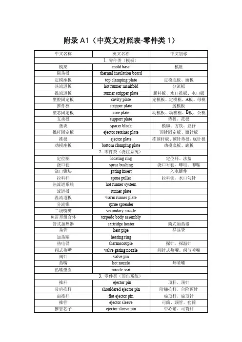
附录A1(中英文对照表-零件类1)中文名称英文名称中文别称1. 零件类(模板)模架mold base 模胚隔热板thermal insulation board定模座板top clamping plate 定模底板、面板热流道板hot runner manifold 分流板推流道板runner stripper plate 脱料板、水口推板、水口板型腔固定板cavity plate 定模板、定模框、A板、母模推件板stripper plate 脱模板型芯固定板core plate 动模板、动模框、B板、公模支承板support plate 垫板、托板垫块spacer block 模脚、方铁、登仔推杆固定板ejector retainer plate 顶针固定板、面针板推板ejector plate 推顶杆板、顶针垫板、底针板动模座板bottom clamping plate 动模底板、底板2. 零件类(浇注系统)定位圈locating ring 定位环、法蓝浇口套sprue bushing 浇口衬套、唧咀、唧嘴浇口镶块gating insert 入水镶件拉料杆sprue puller 拉料销、水口勾针热流道系统hot runner system流道板runner plate温流道板warm runner plate分流锥sprue spreader二级喷嘴secondary nozzle鱼雷形组合体torpedo body assembly管式加热器cartridge heater 筒式加热器热管heat pipe 导热管加热圈heating ring热电偶thermocouple 探针、探温针阀式热嘴valve gating nozzle 阀针式热嘴、阀节喷嘴阀针valve pin热嘴hot nozzle 热喷嘴热嘴垫圈nozzle seat3. 零件类(顶出系统)推杆ejector pin 顶杆、顶针带肩推杆shouldered ejector pin 阶梯推杆、台阶顶针扁推杆flat ejector pin 扁顶杆、扁顶针推管ejector sleeve 司筒、顶管、套筒推管芯子ejector sleeve pin 中心销、司筒针中文名称英文名称中文别称3. 零件类(顶出系统)推块ejector pad 顶块推件环stripper ring 脱模圈斜顶杆angle ejector rod 斜导杆斜顶lifter自润滑活型芯组件slide core guide unit 斜顶滑座导滑座slide base斜导杆固定座angle ejector rod fixed seat自润滑板guide plate挡块baffle block挡块固定螺钉baffle block set screw复位杆return pin 回程销、回针限位块stop block 止动件限位钉stop pin 垃圾钉4. 零件类(成型零部件)型腔cavity 母模仁型芯core 公模仁、模芯侧型芯side core 侧模芯镶件mould insert 镶块型腔镶件cavity insert 上内模、母模入子型芯镶件core insert 下内模、公模入子活动镶件movable insert拼块split螺纹型芯threaded core螺纹型环threaded cavity嵌件insert镶针insert pin5. 零件类(温度调节系统)快速接头jiffy quick connector管接头hose nippler三通接头three way cock四通接头four-way connection弯管接头pipe bend水嘴water nozzle 水接头油嘴oil nozzle 油接头软管hose 喉管水管water tube油管oil tube气管air tube中文名称英文名称中文别称5. 零件类(温度调节系统)管夹hose clip 软管卡子丝堵pipe plug 螺塞、喉塞冷却管cooling pipe隔水片baffle 挡水板O形圈o-ring 密封圈、O形环止水栓stopcock 导流塞流量计flow meter集水器siamese 集水块集油器oil collector 集油块节流阀throttle valve 截流阀流量分配器flow divider 分流器6. 零件类(侧向分型与抽芯机构)滑块slide 行位斜导柱angle pin 斜销、斜导边弯销clog-leg cam锁紧块locking block 楔紧块、铲鸡滑块导板slide glide strip 滑块导轨、压条耐磨板wear plate 硬片、油板球头顶丝ball plunger 波子螺丝、波子弹弓限位块stop block 止动件滑块定位器slide retainer 行位管位7. 零件类(导向、定位系统)导柱guide pin 边钉、导边直身导柱straight leader pins 直导柱带肩导柱shoulder leader pin 台阶导柱推板导柱ejector guide pin 中托边方型导柱guide square 方导柱三板模导柱support pins 细水口导边、水口边三板模导套runner stripper plate bushing 水口板导套、水口套导向条gib block 导向块导套guide bushing 边司直导套straight bushing带肩导套shoulder bushing 有托导套推板导套ejector guide bush 中托司套定位销dowel pin 销钉、管钉定位块locating block直身锁side lock 边锁、侧锁扣、直身定位块斜度锁taper lock 斜度定位块中文名称英文名称中文别称8. 零件类(开关模控制)定距拉杆puller bolt 拉杆螺丝、拉杆定距拉板puller plate 拉板止动螺钉stop bolt 限动螺栓锁模板safety bar 安全杆、锁模扣、安全扣阻尼销parting locks 尼龙拉钩、树脂开闭器、拉模扣分型面锁模装置parting lock set 分型拉钩、扣鸡、扣机顶出预复位机构early ejector return 早回机构、先复位机构9. 零件类(其他功能件)螺钉screw 螺丝螺帽screw cap 螺丝帽内六角螺钉shcs 杯头螺丝内六角沉头螺钉fhcs 平头螺丝无头螺丝grub screw弹簧spring 弹弓圆线弹簧wire spring扁弹簧flat spring氮气弹簧gas spring齿轮gear wheel轴承bearing马达motor止动键locking key卡簧clamp spring油缸hydraulic cylinder 液压缸气缸air cylinder排气阀air evacuation valve支撑柱support pillar 支承柱、撑头承压块pressure block吊模块lifting bars for mold 模具起吊块吊环lifting eye bolts 吊环螺钉挤紧块clamping block 锁定块垫圈washer 垫片弹簧垫圈spring washer 弹垫标牌nameplate 铭牌保护盖protective cover 防护罩顶模块ejector rod 顶出杆、顶棍行程开关position limit switch 限位开关计数器counters中文名称英文名称中文别称9. 零件类(其他功能件)压力传感器pressure transducer日期章date markers 日期标记电源插座power socket公插male connector母插female connector电线electric wire接线盒connection box 接线箱保护盒protection box保护柱stand off调整板adjustment plate压板stopper plate中文名称英文名称中文别称10. 相关术语类(设计系统)模具工程mold engineering工程力学engineering mechanics工程热力学engineering thermodynamics流变学rheology塑料成形模具mould for plastics 塑料模、塑胶模注射模injection mould 注塑模注射模设计design of injection mould热塑性塑料注射模injection mould forthermoplastics热固性塑料注射模injection mould for thermoses双色模double-color mould叠层模stack injection mould热流道模hot runner mould绝热流道模insulated runner mould 温流道模二板模two plate mold 大水口模三板模three plates mold 细水口模浇注系统feed system冷流道系统cold runner system主流道sprue 注入口、注道分流道runner浇口gate 入水浇口形式gate type 入水形式浇口大小gate size 入水大小浇口位置gate location 入水位置直接浇口direct gate 大水口环形浇口ring gate 环型浇口盘形浇口dish gate轮辐浇口spoke gate点浇口pin-point gate 细水口、针点式浇口侧浇口edge gate 边缘浇口潜伏浇口submarine gate 潜水口隧道式浇口tunnel gate 月牙形浇口、牛角形浇口、香蕉形浇口冷料穴cold-slug well 冷料井溢料槽flash groove 跑胶道、流胶沟排气槽air vent 排气道、排气孔、疏气位分型面parting surface 分模面分型线parting line 分模线中文名称英文名称中文别称10. 相关术语类(设计系统)水平分型面(线)horizontal parting line垂直分型面(线)vertical parting line定模fixed half 固定侧动模moving half 可动侧排气系统vent system顶出系统ejection system 脱模系统顶出机构ejection mechanisms 脱模机构成型零部件molding parts冷却系统cooling system冷却通道cooling channel加热系统heating system 供热系统收缩率shrinkage 缩水抽芯力core-pulling force抽芯距core-pulling distance投影面积projected area脱模斜度draft 拔模斜度模具寿命die life模腔数cavity number11. 相关术语类(注塑成型)注射机injection molding machine 注塑机、射出成型机、啤机注射能力shot capacity 注塑容量、注塑能力注射压力injection pressure 注塑压力、射胶压力锁模力clamping force 合模力成型压力moulding pressure 成形压力模内压力internal mould pressure 型腔压力开模力mould opening force脱模力ejection force 顶出力闭合高度mould-shut height最大开距maximum daylight 模板开距脱模距stripper distance最大容模厚度max mold height 最大模厚最小容模厚度min. mould thickness 最小模厚拉杆内距space between tie bars 拉杆间距、导柱内距注射装置injection unit 射胶系统预塑化装置preplasticator合模装置clamping unit 锁模系统控制装置control unit 控制系统机械手mechanical arm 机械臂中文名称英文名称中文别称11. 相关术语类(注塑成型)快速换模系统quick die change system 快速换模装置顺序阀sequence valve喷嘴直径nozzle diameter喷嘴球半径nozzle radius成型周期molding cycle 模塑周期注射时间injection time 射出时间保压时间packing time冷却时间cooling time顶出时间ejection time 脱模时间开、合模时间time of mold open & close塑料Plastics 塑胶塑件plastic parts 塑胶件项目名称project name产品名称product name 品名外观件appearance part总产量total product电镀plating 喷镀油漆paint蚀纹texture 咬花光面shiny side热板焊hot plate welding超声波焊ultrasonic welding 超声焊摩擦焊friction welding振动焊vibration welding壁厚wall thickness加强筋rib圆角fillet尖角sharp corner 锐角、利角凸台convex plate文字text孔位hole location工艺分析process analysis 过程分析流动分析flow analysis 充填分析顶白ejected mark 顶痕毛刺burr 毛边缩痕sink mark 凹痕水波痕water wave effect表面光泽度不良gloss ng中文名称英文名称中文别称11. 相关术语类(注塑成型)银丝纹silver streak 银条纹、银丝气泡bubble黑条纹dark streak烧焦burn 烧伤、烧黑黑点black spots 黑色斑翘曲warpage熔接线weld lines 熔合线熔接痕welding mark 溶合痕尺寸不稳定dimensional instability裂痕flaw 裂缝变色discoloration 褪色困气air trapping缺胶short shot 充填不足、欠注、短射试模mold trial注射速度injection rate 注射速率干燥温度drying temperature 烘干温度干燥时间drying time 烘干时间成型温度injection temperature 注塑温度、喷射温度模具温度mould temperature12. 相关术语类(材料)模板mould plate标准件standard parts电极electrode铜电极copper electrode 铜公石墨电极graphite electrode钨电极tungsten electrode钢steel 钢铁、钢材热作钢hot work tool steel 热锻模具钢冷作钢cold work steel预硬钢prehardened steel碳素钢carbon steel 碳钢碳素工具钢carbon tool steel不锈钢stainless steel铬钼钢chrome molybdenum steel合金工具钢alloy tool steel高速工具钢high speed tool steel硬质合金钢hard alloy steel弹簧钢spring steel中文名称英文名称中文别称12. 相关术语类(材料)灰口铸铁grey cast iron 灰铸铁、灰口铁紫铜copper黄铜brass青铜bronze铍铜BeCu铍青铜beryllium bronze铝aluminum13. 相关术语类(技术参数)结晶性crystallinity 结晶度透明性transparency 透明度耐热性heat resistance 抗热性熔融指数melt index 熔体流动指数剪切速率shear rate 剪切率剪切应力shear stress摩擦系数frictional coefficient布氏硬度brinell hardness HB洛氏硬度rockwell hardness HRC肖氏硬度shore hardness Hs维氏硬度vickers hardness HV金属疲劳metal fatigue疲劳寿命fatigue life密度density重量weight重心centre of gravity面积area体积volume承压面积bearing area 支承面积雷诺数reynolds number导热性thermal conductivity 导热率、导热系数比热容specific heat 比热热量heat quantity温差temperature difference弹性模量modulus of elasticity 弹性模数、杨氏模量截面惯性矩second moment of area 截面二次轴矩截面模量section modulus 截面系数泊松比poisson ratio 横向变形系数拉伸强度tensile strength 抗拉强度压缩强度compressive strength 抗压强度中文名称英文名称中文别称13. 相关术语类(技术参数)屈服强度yield strength剪切强度shear strength 抗剪强度冲击强度impact strength 抗冲强度扭曲强度torsional strength 抗扭强度、扭转强度弯曲强度bending strength 抗弯强度、抗挠强度屈服应力yield stress延展率elongation 延伸率载荷load弹性变形elastic deformation 弹性形变热膨胀系数thermal expansion coefficient14. 相关术语类(表面处理)热处理heat treatment调质thermal refining TR渗碳carburizing退火annealing回火tempering氮化nitriding NT、渗氮真空氮化vacuum nitriding 真空渗氮真空渗碳氮化vacuum carbonitriding 真空碳氮化离子氮化plasma nitriding离子渗碳氮化ion carbonitriding淬火quenching hardening QH高频淬火high frequency hardening真空淬火vacuum hardening化学电镀chemical plating 化学镀阳极氧化处理anodizing 阳极氧化发黑blackening 染黑法喷砂处理sand blast时效处理seasoning15. 相关术语类(加工)加工中心机床machine centers 加工中心CNC铣床cnc milling machine 数控铣床高速铣床high speed milling machine仿形铣床profiling milling machine 靠模铣床仿形车床copy lathe 靠模车床锯床saw machine刨床planing machines磨床grinding machines中文名称英文名称中文别称15. 相关术语类(加工)车床lathe摇臂钻床radial drilling machine 旋臂钻床钻床drilling machine 钻孔机雕刻机engraving machines电火花机electric discharge machines 火花机线切割放电机wire E.D.M. 线割放电加工机测量机measuring machines三座标测量仪three-coordinates measuringmachine合模机die spotting machine机加工machining 切削加工锻造forging铸造casting精密压铸accurate die casting电铸electroforming热轧hot rolling HR冷轧cold rolling 冷压延拉拔draw out挤压extrusion 挤制加工锯削sawing雕削carving-and-scraping铣削milling镗削boring锉削加工filing车削turning钻孔drilling铰孔reaming 铰孔修润拉削broaching刮削scraping磨削grinding研磨加工lapping切削cutting砂纸加工coated abrasive machining抛光加工polishing 抛亮光电火花加工electrical discharge machining 放电加工、EDM 线切割加工spark-erosion wire cutting WEDM电解研磨electrochemical lapping化学研磨chemical polishing中文名称英文名称中文别称15. 相关术语类(制图)技术制图technical drawing 工程制图技术参数technical parameter表面粗糙度surface finish 表面光洁度公差与配合common difference &cooperation形位公差geometric tolerance 几何公差尺寸公差dimension tolerance公差范围tolerance limits 容差极限基孔制basic hole system基轴制basic shaft system三角函数trigonometric function装配图assembly drawing 组装图、总装图、组合图模具排位图die layout 结构草图零件图part drawing 散件图工艺图process drawing 工艺过程图件号no.名称designation实际尺寸actual size标准尺寸stock size材质material 材料、物料数量quantity订货号order no. 订单号备注remarks 附注供应商supplier 供货商模号mold no设计design审核checked by 核对批准approve 审批比例scale单位unit张次sheet版本revision 版次图纸大小drawing sheet size模具公差mold tolerance日期date客户customer技术要求technical requirement 技术条件、技术规定使用说明书operation specifications 操作规范中文名称英文名称中文别称16. 相关术语类(流程、商务)流程优化process optimization 过程优化时间计划表time schedule 工作进度表、时间安排表设计优化design optimization产品分析报告product analysis report流动分析报告flow analysis report结构分析报告structural analysis report模具性能与寿命分析analysis of performance andlife of mold行政部administrative department 行政司营销部marketing department 市场部、市场销售部项目部project department工程部engineering department技术部technical department 技术研发部制造部manufacture department 生产部质检部quality inspection department 品保部采购部purchasing department财务科finance section客服部customer service department 客户服务部董事长board chairman 董事局主席总经理general manager技术总监technical director工程部经理engineering manager制造部经理manufacturing manager 生产部经理模具项目经理mold project manager模具设计师mould designer模具分析师mould analyst项目工程师project engineer钳工fitter模具成本mold cost 模具费用利润profit报价单quotation设计成本design cost 设计费制造成本manufacturing cost 生产成本材料成本material cost 物料成本调试成本debugging cost 调试费用管理成本administration cost 管理费税收revenue交期delivery time 发货期、交货期。
塑料注射成型外文文献翻译、中英文翻译、外文翻译外文翻译原文:Injection MoldingMany different processes are used to transform plastic granules, powders, and liquids into product. The plastic material is in moldable form, and is adaptable to various forming methods. In most cases thermosetting materials require other methods of forming. This is recognized by the fact that thermoplastics are usually heated to a soft state and then reshaped before cooling. Theromosets, on the other hand have not yet been polymerized before processing, and the chemical reaction takes place during the process, usually through heat, a catalyst, or pressure. It is important to remember this concept while studying the plastics manufacturing processes and polymers used.Injection molding is by far the most widely used process of forming thermoplastic materials. It is also one of the oldest. Currently injection molding accounts for 30% of all plastics resin consumption. Since raw material can be converted by a single procedure, injection molding is suitable for mass production of plastics articles and automated one-step production of complex geometries. In most cases, finishing is not necessary. Typical products include toys, automotive parts, household articles, and consumer electronics goods.Since injection molding has a number of interdependent variables, it is a process of considerable complexity. The success of the injection molding operation is dependent not only in the proper setup of the machine hydraulics, barrel temperaturevariations, and changes in material viscosity. Increasing shot-to-shot repeatability of machine variables helps produce parts with tighter tolerance, lowers the level of rejects, and increases product quality (i.e., appearance and serviceability).The principal objective of any molding operation is the manufacture of products: to a specific quality level, in the shortest time, and using repeatable and fully automaticcycle. Molders strive to reduce or eliminate rejected parts in molding production. For injection molding of high precision optical parts, or parts with a high added value such as appliance cases, the payoff of reduced rejects is high.A typical injection molding cycle or sequence consists of five phases;1. Injection or mold filling2. Packing or compression3. Holding4. Cooling5. Part ejectionPlastic granules are fed into the hopper and through an in the injection cylinder where they are carried forward by the rotating screw. The rotation of the screw forces the granules under high pressure against the heated walls of the cylinder causing them to melt. As the pressure building up, the rotating screw is forced backward until enough plastic has accumulated to make the shot. The injection ram (or screw) forces molten plastic from the barrel, through the nozzle, sprue and runner system, and finally into the mold cavities. During injection, the mold cavity is filled volumetrically. When the plastic contacts the cold mold surfaces, it solidifies (freezes) rapidly to produce theskin layer. Since the core remains in the molten state, plastic follows through the core to complete mold filling. Typically, the cavity is filled to 95%~98% during injection. Then the molding process is switched over to the packing phase.Even as the cavity is filled, the molten plastic begins to cool. Since the cooling plastic contracts or shrinks, it gives rise to defects such as sink marks, voids, and dimensional instabilities. To compensate for shrinkage, addition plastic is forced into the cavity. Once the cavity is packed, pressure applied to the melt prevents molten plastic inside the cavity from back flowing out through the gate. The pressure must be applied until the gate solidifies. The process can be divided into two steps (packing and holding) or may be encompassed in one step(holding or second stage). During packing, melt forced into the cavity by the packing pressure compensates for shrinkage. With holding, the pressure merely prevents back flow of the polymer malt.After the holding stage is completed, the cooling phase starts. During, the part is held in the mold for specified period. The duration of the cooling phase depends primarily on the material properties and the part thickness. Typically, the part temperature must cool below the material’s ejection temperature. While cooling the part, the machine plasticates melt for the next cycle.The polymer is subjected to shearing action as well as the condition of the energy from the heater bands. Once the short is made, plastication ceases. This should occur immediately before the end of the cooling phase. Then the mold opens and the part is ejected.When polymers are fabricated into useful articles they are referred to as plastics, rubbers, and fibers. Some polymers, forexample, cotton and wool, occur naturally, but the great majority of commercial products are synthetic in origin. A list of the names of the better known materials would include Bakelite, Dacron, Nylon, Celanese, Orlon, and Styron.Previous to 1930 the use of synthetic polymers was not widespread. However, they should not be classified as new materials for many of them were known in the latter half of the nineteenth century. The failure to develop them during this period was due, in part, to a lack of understanding of their properties, in particular, the problem of the structure of polymers was the subject of much fruitless controversy.Two events of the twentieth century catapulted polymers into a position of worldwide importance. The first of these was the successful commercial production of the plastic now known as Bakelite. Its industrial usefulness was demonstrated in1912 and in the next succeeding years. T oday Bakelite is high on the list of important synthetic products. Before 1912 materials made from cellulose were available, but their manufacture never provided the incentive for new work in the polymer field such as occurred after the advent of Bakelite. The second event was concerned with fundamental studies of the nature polymers by Staudinger in Europe and by Carohers, who worked with the Du Pont company in Delaware. A greater part of the studies were made during the 1920’s. Staudinger’s work was primarily fundamental. Carother’s achievements led t o the development of our present huge plastics industry by causing an awakening of interest in polymer chemistry, an interest which is still strongly apparent today.The Nature of ThermodynamicsThermodynamics is one of the most important areas ofengineering science used to explain how most things work, why some things do not the way that they were intended, and why others things just cannot possibly work at all. It is a key part of the science engineers use to design automotive engines, heat pumps, rocket motors, power stations, gas turbines, air conditioners, super-conducting transmission lines, solar heating systems, etc.Thermodynamics centers about the notions of energy, the idea that energy is conserved is the first low of thermodynamics. It is starting point for the science of thermodynamics is entropy; entropy provides a means for determining if a process is possible.This idea is the basis for the second low of thermodynamics. It also provides the basis for an engineering analysis in which one calculates the maximum amount of useful that can be obtained from a given energy source, or the minimum amount of power input required to do a certain task.A clear understanding of the ideas of entropy is essential for one who needs to use thermodynamics in engineering analysis. Scientists are interested in using thermodynamics to predict and relate the properties of matter; engineers are interested in using this data, together with the basic ideas of energy conservation and entropy production, to analyze the behavior of complex technological systems.There is an example of the sort of system of interest to engineers, a large central power stations. In this particular plant the energy source is petroleum in one of several forms, or sometimes natural gas, and the plant is to convert as much of this energy as possible to electric energy and to send this energy down the transmission line.Simply expressed, the plant does this by boiling water andusing the steam to turn a turbine which turns an electric generator.The simplest such power plants are able to convert only about 25 percent of the fuel energy to electric energy. But this particular plant converts approximately 40 percent;it has been ingeniously designed through careful application of the basic principles of thermodynamics to the hundreds of components in the system.The design engineers who made these calculations used data on the properties of steam developed by physical chemists who in turn used experimental measurements in concert with thermodynamics theory to develop the property data.Plants presently being studied could convert as much as 55 percent of the fuel energy to electric energy, if they indeed perform as predicted by thermodynamics analysis.The rule that the spontaneous flow of heat is always from hotter to cooler objects is a new physical idea. There is noting in the energy conservation principle or in any other law of nature that specifies for us the direction of heat flow. If energy were to flow spontaneously from a block of ice to a surrounding volume of water, this could occur in complete accord with energy conservation. But such a process never happens. This idea is the substance of the second law of thermodynamics.Clear, a refrigerator, which is a physical system used in kitchen refrigerators, freezers, and air-conditioning units must obey not only the first law (energy conservation) but the second law as well.To see why the second law is not violated by a refrigerator, we must be careful in our statement of law. The second law of thermodynamics says, in effect, that heat never flowsspontaneously from a cooler to a hotter object.Or, alternatively, heat can flow from a cooler to a hotter object only as a result of work done by an external agency. We now see the distinction between an everyday spontaneous process, such as the flow of heat from the inside to the outside of a refrigerator.In the water-ice system, the exchange of energy takes place spontaneously and the flow of heat always proceeds from the water to the ice. The water gives up energy and becomes cooler while the ice receives energy and melts.In a refrigerator, on the other hand, the exchange of energy is not spontaneous. Work provided by an external agency is necessary to reverse the natural flow of heat and cool the interior at the expense of further heating the warmer surroundings.译文:塑料注射成型许多不同的加工过程习惯于把塑料颗粒、粉末和液体转化成最终产品。
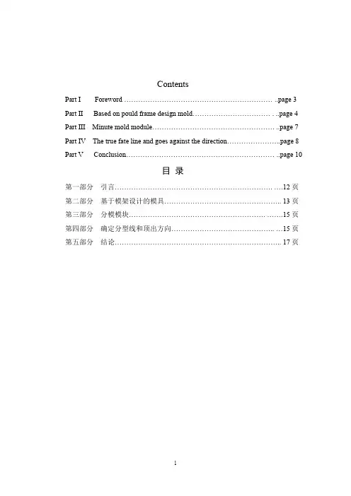
ContentsPart I Foreword ……………………………………………………… ..page 3 Part II Based on pould frame design mold…………………………… . ..page 4 Part III Minute mold module……………………………………………. ..page 7 Part IV The true fate line and goes against the direction…………………..page 8 Part V Conclusion……………………………………………………… ..page 10目录第一部分引言…………………………………………………………. ….12页第二部分基于模架设计的模具………………………………………….. 13页第三部分分模模块…………………………………………………. …….15页第四部分确定分型线和顶出方向…………………………………….. …15页第五部分结论…………………………………………………………….. 17页Plastic injection mold design system1.AbstractThe primary object of the first editeon of this book was to provide a information book on students studying in university, In addition to fulfilling this function, this book has been used increasingly by the novice as an introductory guide, because it progresses in simple stages from the consoderation of basic principles and components to mote detailed ewplanation of themore complex types of special purpose mould。
UGNX模具设计注塑模中英文对照附录A1(中英文对照表-零件类1)中文名称英文名称中文别称1. 零件类(模板)模架mold base 模胚隔热板thermal insulation board定模座板top clamping plate 定模底板、面板热流道板hot runner manifold 分流板推流道板runner stripper plate 脱料板、水口推板、水口板型腔固定板cavity plate 定模板、定模框、A板、母模推件板stripper plate 脱模板型芯固定板core plate 动模板、动模框、B板、公模支承板support plate 垫板、托板垫块spacer block 模脚、方铁、登仔推杆固定板ejector retainer plate 顶针固定板、面针板推板ejector plate 推顶杆板、顶针垫板、底针板动模座板bottom clamping plate 动模底板、底板2. 零件类(浇注系统)定位圈locating ring 定位环、法蓝浇口套sprue bushing 浇口衬套、唧咀、唧嘴浇口镶块gating insert 入水镶件拉料杆sprue puller 拉料销、水口勾针热流道系统hot runner system流道板runner plate温流道板warm runner plate分流锥sprue spreader二级喷嘴secondary nozzle鱼雷形组合体torpedo body assembly管式加热器cartridge heater 筒式加热器热管heat pipe 导热管加热圈heating ring热电偶thermocouple 探针、探温针阀式热嘴valve gating nozzle 阀针式热嘴、阀节喷嘴阀针valve pin热嘴hot nozzle 热喷嘴热嘴垫圈nozzle seat3. 零件类(顶出系统)推杆ejector pin 顶杆、顶针带肩推杆shouldered ejector pin 阶梯推杆、台阶顶针扁推杆flat ejector pin 扁顶杆、扁顶针推管ejector sleeve 司筒、顶管、套筒推管芯子ejector sleeve pin 中心销、司筒针中文名称英文名称中文别称3. 零件类(顶出系统)推块ejector pad 顶块推件环stripper ring 脱模圈斜顶杆angle ejector rod 斜导杆斜顶lifter自润滑活型芯组件slide core guide unit 斜顶滑座导滑座slide base斜导杆固定座angle ejector rod fixed seat自润滑板guide plate挡块baffle block挡块固定螺钉baffle block set screw复位杆return pin 回程销、回针限位块stop block 止动件限位钉stop pin 垃圾钉4. 零件类(成型零部件)型腔cavity 母模仁型芯core 公模仁、模芯侧型芯side core 侧模芯镶件mould insert 镶块型腔镶件cavity insert 上内模、母模入子型芯镶件core insert 下内模、公模入子活动镶件movable insert 拼块split螺纹型芯threaded core螺纹型环threaded cavity嵌件insert镶针insert pin5. 零件类(温度调节系统)快速接头jiffy quick connector管接头hose nippler三通接头three way cock四通接头four-way connection弯管接头pipe bend水嘴water nozzle 水接头油嘴oil nozzle 油接头软管hose 喉管水管water tube油管oil tube气管air tube中文名称英文名称中文别称5. 零件类(温度调节系统)管夹hose clip 软管卡子丝堵pipe plug 螺塞、喉塞冷却管cooling pipe隔水片baffle 挡水板O形圈o-ring 密封圈、O形环止水栓stopcock 导流塞流量计flow meter集水器siamese 集水块集油器oil collector 集油块节流阀throttle valve 截流阀流量分配器flow divider 分流器6. 零件类(侧向分型与抽芯机构)滑块slide 行位斜导柱angle pin 斜销、斜导边弯销clog-leg cam锁紧块locking block 楔紧块、铲鸡滑块导板slide glide strip 滑块导轨、压条耐磨板wear plate 硬片、油板球头顶丝ball plunger 波子螺丝、波子弹弓限位块stop block 止动件滑块定位器slide retainer 行位管位7. 零件类(导向、定位系统)导柱guide pin 边钉、导边直身导柱straight leader pins 直导柱带肩导柱shoulder leader pin 台阶导柱推板导柱ejector guide pin 中托边方型导柱guide square 方导柱三板模导柱support pins 细水口导边、水口边三板模导套runner stripper plate bushing 水口板导套、水口套导向条gib block 导向块导套guide bushing 边司直导套straight bushing带肩导套shoulder bushing 有托导套推板导套ejector guide bush 中托司套定位销dowel pin 销钉、管钉定位块locating block直身锁side lock 边锁、侧锁扣、直身定位块斜度锁taper lock 斜度定位块中文名称英文名称中文别称8. 零件类(开关模控制)定距拉杆puller bolt 拉杆螺丝、拉杆定距拉板puller plate 拉板止动螺钉stop bolt 限动螺栓锁模板safety bar 安全杆、锁模扣、安全扣阻尼销parting locks 尼龙拉钩、树脂开闭器、拉模扣分型面锁模装置parting lock set 分型拉钩、扣鸡、扣机顶出预复位机构early ejector return 早回机构、先复位机构9. 零件类(其他功能件)螺钉screw 螺丝螺帽screw cap 螺丝帽内六角螺钉shcs 杯头螺丝内六角沉头螺钉fhcs 平头螺丝无头螺丝grub screw弹簧spring 弹弓圆线弹簧wire spring扁弹簧flat spring氮气弹簧gas spring齿轮gear wheel轴承bearing马达motor止动键locking key卡簧clamp spring油缸hydraulic cylinder 液压缸气缸air cylinder排气阀air evacuation valve支撑柱support pillar 支承柱、撑头承压块pressure block吊模块lifting bars for mold 模具起吊块吊环lifting eye bolts 吊环螺钉挤紧块clamping block 锁定块垫圈washer 垫片弹簧垫圈spring washer 弹垫标牌nameplate铭牌保护盖protective cover 防护罩顶模块ejector rod 顶出杆、顶棍行程开关position limit switch 限位开关计数器counters中文名称英文名称中文别称9. 零件类(其他功能件)压力传感器pressure transducer日期章date markers 日期标记电源插座power socket公插male connector母插female connector电线electric wire接线盒connection box 接线箱保护盒protection box保护柱stand off调整板adjustment plate压板stopper plate中文名称英文名称中文别称10. 相关术语类(设计系统)模具工程mold engineering工程力学engineering mechanics工程热力学engineering thermodynamics流变学rheology塑料成形模具mould for plastics 塑料模、塑胶模注射模injection mould 注塑模注射模设计design of injection mould 热塑性塑料注射模injection mould forthermoplastics热固性塑料注射模injection mould for thermoses双色模double-color mould叠层模stack injection mould热流道模hot runner mould绝热流道模insulated runner mould 温流道模二板模two plate mold 大水口模三板模three plates mold 细水口模浇注系统feed system冷流道系统cold runner system主流道sprue 注入口、注道分流道runner浇口gate 入水浇口形式gate type 入水形式浇口大小gate size 入水大小浇口位置gate location 入水位置直接浇口direct gate 大水口环形浇口ring gate 环型浇口盘形浇口dish gate轮辐浇口spoke gate点浇口pin-point gate 细水口、针点式浇口侧浇口edge gate 边缘浇口潜伏浇口submarine gate 潜水口隧道式浇口tunnel gate 月牙形浇口、牛角形浇口、香蕉形浇口冷料穴cold-slug well 冷料井溢料槽flash groove 跑胶道、流胶沟排气槽air vent 排气道、排气孔、疏气位分型面parting surface 分模面分型线parting line 分模线中文名称英文名称中文别称10. 相关术语类(设计系统)水平分型面(线)horizontal parting line垂直分型面(线)vertical parting line定模fixed half 固定侧动模moving half 可动侧排气系统vent system顶出系统ejection system 脱模系统顶出机构ejection mechanisms 脱模机构成型零部件molding parts冷却系统cooling system冷却通道cooling channel加热系统heating system 供热系统收缩率shrinkage 缩水抽芯力core-pulling force抽芯距core-pulling distance投影面积projected area脱模斜度draft 拔模斜度模具寿命die life模腔数cavity number11. 相关术语类(注塑成型)注射机injection molding machine 注塑机、射出成型机、啤机注射能力shot capacity 注塑容量、注塑能力注射压力injection pressure 注塑压力、射胶压力锁模力clamping force 合模力成型压力moulding pressure 成形压力模内压力internal mould pressure 型腔压力开模力mould opening force脱模力ejection force 顶出力闭合高度mould-shut height最大开距maximum daylight 模板开距脱模距stripper distance最大容模厚度max mold height 最大模厚最小容模厚度min. mould thickness 最小模厚拉杆内距space between tie bars 拉杆间距、导柱内距注射装置injection unit 射胶系统预塑化装置preplasticator合模装置clamping unit 锁模系统控制装置control unit 控制系统机械手mechanical arm 机械臂中文名称英文名称中文别称11. 相关术语类(注塑成型)快速换模系统quick die change system 快速换模装置顺序阀sequence valve喷嘴直径nozzle diameter喷嘴球半径nozzle radius成型周期molding cycle 模塑周期注射时间injection time 射出时间保压时间packing time冷却时间cooling time顶出时间ejection time 脱模时间开、合模时间time of mold open & close塑料Plastics 塑胶塑件plastic parts 塑胶件项目名称project name产品名称product name 品名外观件appearance part总产量total product电镀plating 喷镀油漆paint蚀纹texture 咬花光面shiny side热板焊hot plate welding超声波焊ultrasonic welding 超声焊摩擦焊friction welding振动焊vibration welding壁厚wall thickness加强筋rib圆角fillet尖角sharp corner 锐角、利角凸台convex plate文字text孔位hole location工艺分析process analysis 过程分析流动分析flow analysis 充填分析顶白ejected mark 顶痕毛刺burr 毛边缩痕sink mark 凹痕水波痕water wave effect表面光泽度不良gloss ng中文名称英文名称中文别称11. 相关术语类(注塑成型)银丝纹silver streak 银条纹、银丝气泡bubble黑条纹dark streak烧焦burn 烧伤、烧黑黑点black spots 黑色斑翘曲warpage熔接线weld lines 熔合线熔接痕welding mark 溶合痕尺寸不稳定dimensional instability裂痕flaw 裂缝变色discoloration 褪色困气air trapping缺胶short shot 充填不足、欠注、短射试模mold trial注射速度injection rate 注射速率干燥温度drying temperature 烘干温度干燥时间drying time 烘干时间成型温度injection temperature 注塑温度、喷射温度模具温度mould temperature12. 相关术语类(材料)模板mould plate标准件standard parts电极electrode铜电极copper electrode 铜公石墨电极graphite electrode钨电极tungsten electrode钢steel 钢铁、钢材热作钢hot work tool steel 热锻模具钢冷作钢cold work steel预硬钢prehardened steel碳素钢carbon steel 碳钢碳素工具钢carbon tool steel不锈钢stainless steel铬钼钢chrome molybdenum steel合金工具钢alloy tool steel高速工具钢high speed tool steel硬质合金钢hard alloy steel弹簧钢spring steel中文名称英文名称中文别称12. 相关术语类(材料)灰口铸铁grey cast iron 灰铸铁、灰口铁紫铜copper黄铜brass青铜bronze铍铜BeCu铍青铜beryllium bronze铝aluminum13. 相关术语类(技术参数)结晶性crystallinity 结晶度透明性transparency 透明度耐热性heat resistance 抗热性熔融指数melt index 熔体流动指数剪切速率shear rate 剪切率剪切应力shear stress摩擦系数frictional coefficient布氏硬度brinell hardness HB洛氏硬度rockwell hardness HRC肖氏硬度shore hardness Hs维氏硬度vickers hardness HV金属疲劳metal fatigue疲劳寿命fatigue life密度density重量weight重心centre of gravity面积area体积volume承压面积bearing area 支承面积雷诺数reynolds number导热性thermal conductivity 导热率、导热系数比热容specific heat 比热热量heat quantity温差temperature difference弹性模量modulus of elasticity 弹性模数、杨氏模量截面惯性矩second moment of area 截面二次轴矩截面模量section modulus 截面系数泊松比poisson ratio 横向变形系数拉伸强度tensile strength 抗拉强度压缩强度compressive strength 抗压强度中文名称英文名称中文别称13. 相关术语类(技术参数)屈服强度yield strength剪切强度shear strength 抗剪强度冲击强度impact strength 抗冲强度扭曲强度torsional strength 抗扭强度、扭转强度弯曲强度bending strength 抗弯强度、抗挠强度屈服应力yield stress 延展率elongation 延伸率载荷load弹性变形elastic deformation 弹性形变热膨胀系数thermal expansion coefficient14. 相关术语类(表面处理)热处理heat treatment调质thermal refining TR渗碳carburizing退火annealing回火tempering氮化nitriding NT、渗氮真空氮化vacuum nitriding 真空渗氮真空渗碳氮化vacuum carbonitriding 真空碳氮化离子氮化plasma nitriding离子渗碳氮化ion carbonitriding淬火quenching hardening QH高频淬火high frequency hardening真空淬火vacuum hardening化学电镀chemical plating 化学镀阳极氧化处理anodizing 阳极氧化发黑blackening 染黑法喷砂处理sand blast时效处理seasoning15. 相关术语类(加工)加工中心机床machine centers 加工中心CNC铣床cnc milling machine 数控铣床高速铣床high speed milling machine仿形铣床profiling milling machine 靠模铣床仿形车床copy lathe 靠模车床锯床saw machine刨床planing machines磨床grinding machines中文名称英文名称中文别称15. 相关术语类(加工)车床lathe摇臂钻床radial drilling machine 旋臂钻床钻床drilling machine 钻孔机雕刻机engraving machines电火花机electric discharge machines 火花机线切割放电机wire E.D.M. 线割放电加工机测量机measuring machines三座标测量仪three-coordinates measuringmachine合模机die spotting machine机加工machining 切削加工锻造forging铸造casting精密压铸accurate die casting电铸electroforming热轧hot rolling HR冷轧cold rolling 冷压延拉拔draw out挤压extrusion 挤制加工锯削sawing雕削carving-and-scraping铣削milling镗削boring锉削加工filing车削turning钻孔drilling铰孔reaming 铰孔修润拉削broaching刮削scraping磨削grinding研磨加工lapping切削cutting砂纸加工coated abrasive machining抛光加工polishing 抛亮光电火花加工electrical discharge machining 放电加工、EDM 线切割加工spark-erosion wire cutting WEDM电解研磨electrochemical lapping化学研磨chemical polishing中文名称英文名称中文别称15. 相关术语类(制图)技术制图technical drawing 工程制图技术参数technical parameter表面粗糙度surface finish 表面光洁度公差与配合common difference &cooperation形位公差geometric tolerance 几何公差尺寸公差dimension tolerance公差范围tolerance limits 容差极限基孔制basic hole system基轴制basic shaft system三角函数trigonometric function装配图assembly drawing 组装图、总装图、组合图模具排位图die layout 结构草图零件图part drawing 散件图工艺图process drawing 工艺过程图件号no.名称designation实际尺寸actual size标准尺寸stock size材质material 材料、物料数量quantity订货号order no. 订单号备注remarks 附注供应商supplier 供货商模号mold no设计design审核checked by 核对批准approve 审批比例scale单位unit张次sheet版本revision 版次图纸大小drawing sheet size模具公差mold tolerance日期date客户customer技术要求technical requirement 技术条件、技术规定使用说明书operation specifications 操作规范中文名称英文名称中文别称16. 相关术语类(流程、商务)流程优化process optimization 过程优化时间计划表time schedule 工作进度表、时间安排表设计优化design optimization产品分析报告product analysis report流动分析报告flow analysis report结构分析报告structural analysis report模具性能与寿命分析analysis of performance andlife of mold行政部administrative department 行政司营销部marketing department 市场部、市场销售部项目部project department工程部engineering department技术部technical department 技术研发部制造部manufacture department 生产部质检部quality inspection department 品保部采购部purchasing department财务科finance section客服部customer service department 客户服务部董事长board chairman 董事局主席总经理general manager技术总监technical director工程部经理engineering manager制造部经理manufacturing manager 生产部经理模具项目经理mold project manager模具设计师mould designer模具分析师mould analyst项目工程师project engineer钳工fitter模具成本mold cost 模具费用利润profit报价单quotation设计成本design cost 设计费制造成本manufacturing cost 生产成本材料成本material cost 物料成本调试成本debugging cost 调试费用管理成本administration cost 管理费税收revenue 交期delivery time 发货期、交货期。
模具外文翻译外文文献英文文献注塑模The Injection Molding1、The injection moldingInjection molding is principally used for the production of the thermoplastic parts,although some progress has been made in developing a method for injection molding some thermosetting materials.The problem of injection a method plastic into a mold cavity from a reservoir of melted material has been extremely difficult to solve for thermosetting plastic which cure and harden under such conditions within a few minutes.The principle of injection molding is quite similar to that of die-casting.The process consists of feeding a plastic compound in powered or granular form from a hopper through metering and melting stages and then injecting it into a mold.After a brief cooling period,the mold is opened and the solidified part ejected.Injection-molding machine operation.The advantage of injection molding are:(ⅰ)a high molding speed adapter for mass production is possible;(ⅱ)there is a wide choice of thermoplastic materials providing a variety of useful properties;(ⅲ)it is possible to mold threads,undercuts,side holes,and large thin section.2、The injection-molding machineSeveral methods are used to force or inject the melted plastic into the mold.The most commonly used system in the larger machines is the in-line reciprocating screw,as shown in Figure 2-1.The screw acts as a combination injection and plasticizing unit.As the plastic is fed to the rotating screw,it passes through three zones as shown:feed,compression,and metering.After the feed zone,the screw-flight depth is gradually reduced,force theplastic to compress.The work is converted to heat by conduction from the barrel surface.As the chamber in front of the screw becomes filled,it forces the screw back,tripping a limit switch that activates a hydraulic cylinder that forces the screw forward and injects the fluid plastic into the closed mold.An antiflowback valve presents plastic under pressure from escaping back into the screw flight.The clamping force that a machine is capable of exerting is part of the size designation and is measured in tons.A rule-of-thumb can be used to determine the tonnage required for a particular job.It is based on two tons of clamp force per square inch of projected area.If the flow pattern is difficult and the parts are thin,this may have to go to three or four tons.Many reciprocating-screw machines are capable of handing thermosetting plastic materials.Previously these materials were handled by compression or transfer molding.Thermosetting materials cure or polymerize in the mold and are ejected hot in the range of 375°C~410°C.T hermosetting parts must be allowed to cool in the mold in order or remove them without distortion. Thus thermosetting cycles can be faster.Of course the mold must be heated rather than chilled,as with thermoplastics.3、Basic Underfeed MouldA simple mould of this type is shown in Figure3-1,and the description of the design and the opening sequence follows.The mould consists of three basic parts,namely:the moving half,the floating cavity plate and the feed plate respectively.The moving half consists of The moving mould plate assembly,support block,backing plate,ejector assembly and the pin ejection system.Thus the moving half in this design is identical with the moving half of basic moulds.The floating cavity plate,which may be of the integer or insert-bolster design,is located on substantial guide pillars(not shown)fitted in the feed plate.These guide pillars must be of sufficient length to support the floating cavity plate over its full movement and still project to perform the function of alignment between the cavity and core when the mould is being closed.Guide bushes are fitted into the moving mould plate and the floating cavity plate respectively.The maximum movement of the floating cavity plate is controlled by stop or similar device.The moving mould plate is suitably bored to provide a clearance for the stop bolt assembly.The stop bolts must be long enough to provide sufficient space between the feed plate and the floating cavity plate for easy removal of the feed system.The minimum space provide for should be 65mm just sufficient for an operator to remove the feed system by hand if necessary.The desire operating sequence is for the first daylight to occur between the floating cavity plate.This ensures the sprue is pulled from the sprue bush immediately the mouldis opened.T o achieve this sequence,springs may be incorporated between the feed plate and the floating cavity plate.The springs should be strong enough to give an initial impetus to the floating cavity plate to ensure it moves away with the moving half.It is normal practice to mount the springs on the guide pillars(Figure3-2)and accommodate them in suitable pocket in the cavity plate.The major part of the feed system(runner and sprue)is accommodated in the feed plate to facilitate automatic operation,the runner should be of a trapezoidal form so that once it is pulled from the feed plate is can easily beextracted.Note that if a round runner is used,half the runner is formed in the floating cavity plate,where it would remain,and be prevented from falling or being wiped clear when the mould is opened.Now that we have considered the mould assembly in the some detail,we look at the cycle of operation for this type of mould.The impressions are filled via the feed system(Figure3-1(a))and after a suitable dwell period,the machine platens commence to open.A force is immediately exerted by the compression springs,which cause the floating cavity plate to move away with the moving half as previously discussed.The sprue is pulled from the sprue bush by the sprue puller.After the floating cavity plate has moved a predetermined distance,it is arrested by the stop bolts.The moving half continues to move back and the moldings,having shrunk on to the cores,are withdrawn from the cavities.The pin gate breaks at its junction with the runner(Figure3-1(b)).The sprue puller,being attached to the moving half,is pulled through the floating cavity plate and thereby release the feed system which is then free to fall between the floating cavity plate and the feed plate.The moving half continues to move back until the ejector system is operated and the moldings are ejected (Figure3-1(c)).When the mould is closed,the respective plates are returned to their molding position and the cycle is repeated.4、Feed SystemIt is necessary to provide a flow-way in the injection mould to connect the nozzle(of the injection machine)to each impression.This flow-way is termed the feed system.Normally thefeed system comprises a sprue,runner and gate.These terms applyequally to the flow-way itself,and to the molded material which is remove from the flow-way itself in the process of extracted the molding.A typical feed system for a four-impression,two plate-type mould is shown in Figure4-1.It is seen that the material passes through the sprue,main runner,branch runner and gate before entering the impression.As the temperature of molten plastic is lowered which going through the sprue and runner,the viscosity will rise;however,the viscosity is lowered by shear heat generated when going through the gate to fill the cavity.It is desirable to keep the distance that the material has to travel down to a minimum to reduce pressure and heat losses.It is for this reason that careful consideration must be given to the impression layout gate’s design.4.1.SprueA sprue is a channel through which to transfer molten plastic injected from the nozzle of the injector into the mold.It is a part of sprue bush,which is a separate part from the mold.4.2.RunnerA runner is a channel that guides molten plastic into the cavity of a mold.4.3.GateA gate is an entrance through which molten plastic enters the cavity.The gate has the following function:restricts the flow and the direction of molten plastic;simplifies cutting of a runner and moldings to simplify finishing of parts;quickly cools and solidifies to avoid backflow after molten plastic has filled up in the cavity.4.4.Cold slug wellThe purpose of the cold slug well,shown opposite the sprue,is theoretically to receive the material that has chilled at the front of nozzle during the cooling and ejection phase.Perhaps of greater importance is the fact that it provides position means whereby the sprue bush for ejection purposes.The sprue,the runner and the gate will be discarded after a part is complete.However,the runner and the gate are important items that affect the quality or the cost of parts.5、EjectionA molding is formed in mould by injecting a plastic melt,under pressure,into animpression via a feed system.It must therefore be removed manually.Furthermore,all thermoplastic materials contract as they solidify,which means that the molding will shrink on to the core which forms it.This shrinkage makes the molding difficult to remove. Facilities are provided on the injection machine for automatic actuation of an ejector system,and this is situated behind the moving platen.Because of this,the mould’s ejector system will be most effectively operated if placed in the moving half of the mould,i.e. the half attached to the moving platen.We have stated previously that we need to eject the molding from the core and it therefore follows that the core,too,will most satisfactorily be located in the moving half.The ejector system in a mould will be discussed under three headings,namely:(ⅰ)the ejector grid;(ⅱ)the ejector plate assembly; and(ⅲ)the method of ejection.5.1、Ejector gridThe ejector grid(Figure5-1)is that part of the mould which supports the mould plate and provides a space into which theejector plate assembly can be fitted and operated.The grid normally consists of a back plate on to which is mounted a number of conveniently shaped “support blocks”.The ejector plate assembly is that part of the mould to which the ejector element is attached.The assembly is contained in a pocket,formed by the ejector grid,directly behind the mould plate.The assembly(Figure5-2)consists of an ejector plate,a retaining plate and an ejector rod.One end of this latter member is threaded and it is screwed into the ejector plate.In this particular design the ejector rod function not only as an actuating member but also as a method of guiding the assembly.Note that the parallel portion of the ejector rod passes through an ejector rod bush fitted in the back plate of the mould.5.2、Ejection techniquesWhen a molding cools,it contracts by an amount depending on the material being processed.For a molding which has no internal form,for example,a solid rectangular block,the molding will shrink away from the cavity walls,thereby permitting a simple ejection technique to be adopted.However,when the molding has internal form,the molding,as it cools,will shrink onto the core and some positive type of ejection is necessary.The designer has several ejection techniques from which to choose,but in general,the choice will be restricted depending upon the shape of the molding.The basic ejection techniques are as follows:(ⅰ)pin ejection(ⅱ)sleeve ejection(ⅲ)stripper plate ejection and(Ⅳ)air ejection.Figure 2-1aFigure 2-1bFigure 3-1Figure 3-2Figure 4-1aFigure 4-1bFigure 5-1Figure 5-2注塑模1、注塑模尽管成型某些热固性材料的方法取得了一定的进步,但注塑模主要(还是)用来生产热塑性塑件。
A CAD/CAE-integrated injection mold design system for plastic productsAbstract Mold design is a knowledge-intensive process. This paper describes a knowledge-based oriented, parametric, modular and feature-based integrated computer-aided design/computer-aided engineering (CAD/CAE) system for mold design. Development of CAx systems for numerical simulation of plastic injection molding and mold design has opened new possibilities of product analysis during the mold design. The proposed system integrates Pro/ENGINEER system with the specially developed module for the calculation of injection molding parameters, mold design, and selection of mold elements. The system interface uses parametric and CAD/CAE feature-based database to streamline the process of design, editing, and reviewing. Also presented are general structure and part of output results from the proposed CAD/ CAE-integrated injection mold design system.Keywords Mold design . Numerical simulation . CAD . CAE1 IntroductionInjection molding process is the most common molding process for making plastic parts. Generally, plastic injection molding design includes plastic product design, mold design, and injection molding process design, all of which contribute to the quality of the molded product as well as production efficiency [1]. This is process involving many design parameters that need to be considered in a concurrent manner. Mold design for plastic injection molding aided by computers has been focused by a number of authors worldwide for a long period. Various authors have developed program systems which help engineers to design part, mold, and selection parameters of injection molding. During the last decade, many authors have developed computer-aided design/computer-aided engineering (CAD/CAE) mold design systems for plastic injection molding. Jong et al. [2] developed a collaborative integrated design system for concurrent mold design within the CAD mold base on the web, using Pro/E. Low et al. [3] developed an application for standardization of initial design of plastic injection molds. The system enables choice and management of mold base of standard mold plates, but does not provide mold and injection molding calculations. The authors proposed a methodology of standardizing the cavity layout design system for plastic injection mold such that only standard cavity layouts are used. When standard layouts are used, their layout configurations can be easilystored in a database. Lin at al. [4, 5] describe a structural design system for 3D drawing mold based on functional features using a minimum set of initial information. In addition, it is also applicable to assign the functional features flexibly before accomplishing the design of a solid model for the main parts of a drawing mold. This design system includes modules for selection and calculation of mold components. It uses Pro/E modules Pro/Program and Pro/Toolkit, and consists of modules for mold selection, modification and design. Deng et al. [6, 7] analyzed development of the CAD/CAE integration. The authors also analyzed systems and problems of integration between CAD and CAE systems for numerical simulation of injection molding and mold design. Authors propose a feature ontology consisting of a number of CAD/CAE features. This feature represents not only the geometric information of plastic part, but also the design intent is oriented towards analysis. Part features contain the overall product information of a plastic part, wall features, development features (such as chamfer, ribs, boss, hole, etc.), treatment features which contain analysis-related design information and sub wall developed features. Wall and development features are so called “component features〞. God ec et al. [8, 9] developed a CAE system for mold design and injection molding parameters calculations. The system is based on morphology matrix and decision diagrams. The system is used for thermal, rheological and mechanical calculation, and material base management,Fig. 1 General structure of integrated injection mold design system for plastic productsbut no integration with commercial CAx software is provided. Huang et al. [10] developed a mold-base design system for injection molding. The database they used was parametric and feature-based oriented. The system used Pro/E for modeling database components. Kong et al. [11]developed a parametric 3D plastic injection mold design system integrated with solid works. Other knowledge-based systems, such as IMOLD, ESMOLD, IKMOULD, and IKBMOULD, have been developed for injection mold design. IMOLD divides mold design into four major steps; parting surface design, impression design, runner system design, and mold-base design. The software uses a knowledge-based CAD system to provide an interactive environment, assist designers in the rapid completion of mold design, and promote the standardization of the mold design process. IKB-MOULD application consists of databases and knowledge bases for mold manufacturing. Lou et al. [12] developed an integrated knowledge-based system for mold base design. The system has module for impression calculation, dimension calculation, calculation of the number of mold plates and selection of injection machine. The system uses Pro/ Mold Base library. This paper describes KBS and key technologies, such as product modeling, the frame-rule method, CBS, and the neural networks. A multilayer neural network has been trained by back propagation BP. This neural network adopts length, width, height and the number of parts in the mold as input and nine parameters (length, width, and height of up and down set-in, mold bases side thickness, bottom thickness of the core, and cavity plates) as output. Mok et al. [13, 14] developed an intelligent collaborative KBS for injection molds. Mok at el. [15] has developed an effective reuse and retrieval system that can register modeled standard parts using a simple graphical user interface even though designers may not know the rules of registration for a database. The mold design system was developed using an Open API and commercial CAD/computer aided manufacturing (CAM)/CAE solution. The system was applied to standardize mold bases and mold parts in Hyundai Heavy Industry. This system adopted the method of design editing, which implements the master model using features. The developed system provides methods whereby designers can register the master model, which is defined as a function of 3D CAD, as standard parts and effectively reuse standard parts even though they do not recognize the rules of the database.Todic et al. [16] developed a software solution for automated process planning for manufacturing of plastic injection molds. This CAD/CAPP/CAM system does not provide CAE calculation of parameters of injection molding and mold design. Maican et al. [17] used CAE for mechanical, thermal, and rheological calculations. They analyzed physical, mechanical, and thermal properties of plastic materials. They defined the critical parameters of loaded part. Nardinet al. [18] tried to develop the system which would suit all the needs of the injection molding for selection of the part–mold–technology system. The simulation results consist of geometrical and manufacturing data. On the basis of the simulation results, part designers can optimize part geometry, while mold designers can optimize the running and the cooling system of the mold. The authors developed a program which helps the programmers of the injection molding machine to transfer simulation data directly to the machine. Zhou et al. [1] developed a virtual injection molding system based on numerical simulation. Ma et al. [19] developed standard component library for plastic injection mold design using an object-oriented approach. This is an objector iented, library model for defining mechanical components parametrically. They developed an object-oriented mold component library model for incorporating different geometric topologies and non-geometric information. Over the years, many researchers have attempted to automate a wholeFig. 2 Structure of module for numerical simulation of injection molding processFig. 3 Forms to define the mold geometrymold design process using various knowledge-based engineering (KBE) approaches, such as rule-based reasoning (RBR), and case base (CBR) and parametric design template (PDT). Chan at al. [20] developed a 3D CAD knowledge-based assisted injection mold design system (IKB mold). In their research, design rules and expert knowledge of mold design were obtained from experienced mold designers and handbooks through various traditional knowledge acquisition processes. The traditional KBE approaches, such as RBR, CBR, and simple PDT have been successfully applied to mold cavity and runner layout design automation of the one product mold. Ye et al. [21] proposed a feature-based and object-oriented hierarchical representation and simplified symbolic geometry approach for automation mold assembly modeling. The previously mentioned analysis of various systems shows that authors used different ways to solve the problems of mold design by reducing it to mold configureator (selector). They used CAD/CAE integration for creating precision rules for mold-base selection. Many authors used CAE system for numerical simulation of injection molding to define parameters of injection molding. Several also developed original CAE modules for mold and injection molding process calculation. However, common to all previously mentioned systems is the lack of module for calculation of mold and injection molding parameters which would allow integration with the results of numerical simulation. This leads to conclusion that there is a need to create a software system which integrates parameters of injection molding with the result obtained by numericalFig. 4 Forms to determine the distance between the cooling channels and mold cavityFig. 5 Mold-base selector formssimulation of injection molding, mold calculation, and selection. All this would be integrated into CAD/CAE-integrated injection mold design system for plastic products.2 Structure of integrated CAD/CAE systemAs is well known, various computational approaches for supporting mold design systems of various authors use design automation techniques such as KBE (RBR, CBR, PDT) or design optimisation techniques such as traditional (NLP,LP, BB, GBA, IR, HR) or meta heuristic search such as (TS, SA, GA) and other special techniques such as (SPA, AR, ED).The developed interactive software system makes possible to perform: 3D modeling of the parts, analysis of part design and simulation model design, numerical simulation of injection molding, and mold design with required calculations.The system consists of four basic modules:& Module for CAD modeling of the part& Module for numerical simulation of injection molding processFig. 6 Form for mechanical mold calculation& Module for calculation of parameters of injection molding and mold design calculation and selection& Module for mold modeling (core and cavity design and design all residual mold components) The general structure of integrated injection mold design system for plastic products is shown in Fig. 1.2.1 Module for CAD modeling of the part (module I)The module for CAD modeling of the part is the first module within the integrated CAD/CAE system. This module is used for generating CAD model of the plastic product and appropriate simulation model. The result of this module is solid model of plastic part with all necessary geometrical and precision specifications. Precision specifications are: project name, number, feature ID, feature name, position of base point, code number of simulation annealing, trade material name, material grade, part tolerance, machine specification (name, clamping force, maximal pressure, dimensions of work piece), and number of cavity. If geometrical and precision specification is specified (given) with product model, the same are used as input to the nextmodule, while this module is used only to generate the simulation model.2.2 Module for numerical simulation of injection molding process (module II)Module II is used for numerical simulation of injection molding process. User implements an iterative simulation process for determining the mold ability parameters of injection molding and simulation model specification. The structure of this module is shown in Fig. 2.After a product model is imported and a polymer is selected from the plastic material database, user selects the best location for gating subsystem. The database contains rheological, thermal, and mechanical properties of plastic materials. User defines parameters of injection molding and picks the location for the gating subsystem. Further analyses are carried out: the plastic flow, fill time, injection pressure, pressure drop, flow front temperature, presence of weld line, presence of air traps, cooling quality, etc.The module offers four different types of mold flow analysis. Each analysis is aimed at solving specific problems:& Part analysis—This analysis is used to test a known gate location, material, and part geometry to verify that a part will have acceptable processing conditions.& Gate analysis—This analysis tests multiple gate locations and compares the analysis outputs to determine the optimal gate location.& Sink mark analysis—This analysis detects sink mark locations and depths to resolve cosmetic problems before the mold is built eliminating quality disputes that could arise between the molder and the customer.The most important parameters are the following: [22]& Part thickness& Flow length& Radius and drafts,& Thickness transitions& Part material& Location of gates& Number of gates& Mold temperature& Melt temperature& Injection pressure& Maximal injection molding machine pressureIn addition to the previously mentioned parameters of injection molding, the module shows following simulation results: welding line position, distribution of air traps, the distribution of injection molding pressure, shear stressFig. 7 Segment of the mechanical calculation algorithmdistribution, temperature distribution on the surface of the simulation model, the quality of filling of a simulation model, the quality of a simulation model from the standpoint of cooling, and time of injection molding [22, 23]. A part of output results from this module are the input data for thenext module. These output results are: material grade and material supplier, modulus of elasticity in the flow direction, modulus of elasticity transverse direction, injection pressure, ejection temperature, mold temperature, melting temperature, highest melting temperature thermoplastic, thermoplastic density in liquid and solid state, and maximum pressure of injection molding machine. During implementation of iterative SA procedure, user defines the moldability simulation model and the parameters of injection molding. All results are represented by different colors in the regions of the simulation model.2.3 Module for calculation of parameters of injection molding and mold design calculation and selection (module III)This module is used for analytical calculations, mold sizing, and its selection. Two of the more forms for determining the dimensions of core and cavity mold plates are shown in Fig. 3.Based on the dimensions of the simulation model and clamping force (Fig. 3) user selects the mold material and system calculates the width and length of core and cavity plates. Wall thickness between the mold cavity to the cooling channel can be calculated with the following three criteria: criterion allowable shear stress, allowable bending stress criterion, and the criterion of allowable angle isotherms are shown in Fig. 4 [22, 24]. The system adopts the maximum value of comparing the values of wall thickness calculated by previously mentioned criteria.Fig. 8 Forms for standard mold plates selectionFig. 9 Forms for mold plate model generationBased on the geometry of the simulation model, user select shape and mold type. Forms for the selection mold shape, type, and subsystems are shown in Fig. 5. Once these steps are completed, user implements the thermal, rheological, and mechanical calculation of mold specifications. An example of one of the several forms for mechanical mold calculation is shown in Fig. 6.Segment of the algorithm of mechanical calculations is shown in Fig. 7.f max maximal flexure of cavity platef dop allowed displacement of cavity plateε elastic deformationαmin minimal value of shrinkage factorE k modulus of elasticity of cavity plateG shear modulusS k wall thickness distance measuring between cavity and waterlined KT cooling channel diameterAfter the thermal, rheological, and mechanical calculations, user selects mold plates from the mold base. Form for the selection of standard mold plates is shown in Fig. 8. The system calculates the value of thickness of risers, fixed, and movable mold plates (Fig. 8). Based on the calculated dimensions, the system automatically adopts the first major standard value for the thickness of risers, movable, and fixed mold plate. Calculation of the thickness and the adoption of standard values are presented in the form as shown in Fig. 8.The interactive system recommends the required mold plates. The module loads dimensions from the database and generates a solid model of the plate. After the plate selection, the plate is automatically dimensioned, material plate isFig. 10 Structure of module IVassigned, and 3D model and 2D technical drawing are generated on demand. Dimensions of mold component (e.g., fixed plate) are shown in the form for mold plate mode generation, as shown inThe system loads the plate size required from the mold base. In this way, load up any other necessary standard mold plates that make up the mold subassembly. Subassembly mold model made up of instance plates are shown in Fig. 10Then get loaded other components of subsystems as shown in Fig. 5. Subsystem for selection other components include bolts and washers. The way of components selection are based on a production rules by authors and by company “D-M-E〞[25, 26].2.4 Module for mold modeling (core and cavity design and design all residual mold components; module IV)This module is used for CAD modeling of the mold (core and cavity design). This module uses additional software tools for automation creating core and cavity from simulation (reference) model including shrinkage factor of plastics material and automation splitting mold volumes of the fixed and movable plates. The structure of this module is shown in Fig. 11.Additional capability of this module consists of software tools for:& Applying a shrinkage that corresponds to design plastic part, geometry, and molding conditions, which are computed in module for numerical simulation& Make conceptual CAD model for nonstandard plates and mold components& Design impression, inserts, sand cores, sliders and other components that define a shape of molded part& Populate a mold assembly with standard components such as new developed mold base which consists of DME mold base and mold base of enterprises which use this system, and CAD modeling ejector pins, screws, and other components creating corresponding clearance holes& Create runners and waterlines, which dimensions was calculated in module for calculating of parameters of injection molding and mold design calculation and selection& Check interference of components during mold opening, and check the draft surfacesAfter applied dimensions and selection mold components, user loads 3D model of the fixed (core) and movable (cavity) plate. Geometry mold specifications, calculated in the previous module, are automatically integrated into this module, allowing it to generate the final mold assembly. Output from this module receives the complete mold model of the assembly as shown in Fig. 15. Thismodule allowsFig. 11 Subassembly model of moldFig. 12 CAD model of the test Productmodeling of nonstandard and standard mold components that are not contained in the mold base.3 Case studyThe complete theoretical framework of the CAD/CAE-integrated injection mold design system for plastic products was presented in the previous sections. In order to complete this review, the system was entirely tested on a real case study. The system was tested on few examples of similar plastic parts. Based on the general structure of the model of integrated CAD/CAE design system shown in Fig. 1, the authors tested the system on some concrete examples. One of the examples used for verification of the test model of the plastic part is shown in Fig. 12.The module for the numerical simulation of injection molding process defines the optimal location for setting gating subsystem. Dark blue regions indicate the optimal position for setting gating subsystem as shown in Fig. 13.Based on dimensions, shape, material of the case study product (Fig. 11), optimal gating subsystem location (Fig. 13), and injection molding parameters (Table 1), the simulation model shown in Fig. 14 was generated.One of the rules for defining simulation model gate for numerical simulation:IF (tunnel, plastic material, mass) THEN prediction dimension (upper tunnel, length, diameter1, diameter2, radius, angle, etc.)Part of the output results from module II, which are used in module III are shown in Table 1.Fig. 13 Optimal gating subsystem location in the partTable 1 Part of the output results from the module for the numerical simulation of injection molding processMaterial grade and material supplier Acrylonitrile butadiene styrene 780(ABS 780),Kumho Chemicals Inc.Max injection pressure 100 MPaMold temperature 60°C ili 40Melt Temperature 230°CInjection Time 0,39 s 0,2 sInjection Pressure 27,93 MPaRecommended ejection temperature 79°CModulus of elasticity, flow direction for ABS 780 2,600 MPaModulus of elasticity, transverse direction for ABS 780 2,600 MPaPoision ratio in all directions for ABS 780 0.38Shear modulus for ABS 780 942 MPaDensity in liquid state 0.94032 g/cm3Density in solid state 1.047 g/cm3In module III, the system calculates clamping force F=27.9 kN (Fig. 3), cooling channel diameter d KT=6 mm, cooling channel length lKT090 mm (Fig. 4). Given the shape and dimensions of the simulation model, square shape of mold with normal performance was selected as shown in Fig. 5. Selected mold assembly standard series: 1,616, length and width of mold housing 156×156 mm as shown in Fig. 8. In the segment of calculation shown in Fig. 8, mold design system panel recommends the following mold plates:& Top clamping plate N03-1616-20& Bottom clamping plate N04-1616-20& Fixed mold plate (core plate) N10A-1616-36& Movable plate (cavity plate) N10B-1616-36& Support plate N20-1616-26& Risers N30-1616-46& Ejector retainer plate N40-1616-10& Ejector plate N50-1616-12After finishing the fixed and movable mold plates from the standpoint of CAD modeling core and cavity plates, cooling channel, followed by manual selection of other mold standard components such as sprue bush, locating ring, guide pins, guide bush, leading bushing guide, spacer plates, screws (M4×10, M10×100, M10×30, M6×16, M10×30, etc.) and modeling nonstandard mold components (if any) ejector pins, ejector holes, inserts etc. A complete model of the mold assembly with tested simulation model is shown in Fig. 15.Fig. 14 Simulation model of plastic partFig. 15 Model of the mold assembly with tested simulation model4 ConclusionThe objective of this research was to develop a CAD/CAE integrated system for mold design which is based on Pro/ ENGINEER system and uses specially designed and developed modules for mold design. This paper presents a software solution for multiple cavity mold of identical molding parts, the so-called one product mold. The system is dedicated to design of normal types of molds for products whose length and width are substantially greater than product height, i.e., the system is customized for special requirements of mold manufacturers. The proposed system allows full control over CAD/CAE feature parameters which enables convenient and rapid mold modification. The described CAD/CAE modules are feature-based, parametric, based on solid models, and object oriented. The module for numerical simulation of injection molding allows the determination selection of injection molding parameters. The module for calculation of parameters of injection molding process and mold design calculation and selection improves design Fig. 15 Model of the mold assembly with tested simulation model faster, reduces mold design errors, and provides geometric and precision information necessary for complete mold design. The knowledge base of the system can be accessed by mold designers through interactive modules so that their own intelligence and experience can also be incorporated into the total mold design. Manufacture of the part confirms that the developed CAD/CAE system provides correct results and proves to be a confident software tool.Future research will be directed towards three main goals. The first is to develop a system for automation of family mold design. Another line of research is the integration with CAPP system for plastic injection molds manufacturing developed at the Faculty of Technical Sciences. Finally, following current trends in this area, a collaborative system using web technologies and blackboard architecture shall be designed and implemented.塑料制品的CAD / CAE集成的注塑模具设计系统摘要:模具设计是一个知识密集的过程。
外文资料翻译系部:专业:姓名:学号:外文出处:dvanced English literacy course(用外文写)附件:指导老师评语签名:年月日第一篇译文(中文)2.3注射模2.3.1注射模塑注塑主要用于热塑性制件的生产,它也是最古老的塑料成型方式之一。
目前,注塑占所有塑料树脂消费的30%。
典型的注塑产品主要有杯子器具、容器、机架、工具手柄、旋钮(球形捏手)、电器和通讯部件(如电话接收器),玩具和铅管制造装置。
聚合物熔体因其较高的分子质量而具有很高的粘性;它们不能像金属一样在重力流的作用下直接被倒入模具中,而是需要在高压的作用下强行注入模具中。
因此当一个金属铸件的机械性能主要由模壁热传递的速率决定,这决定了最终铸件的晶粒度和纤维取向,也决定了注塑时熔体注入时的高压产生强大的剪切力是物料中分子取向的主要决定力量。
由此所知,成品的机械性能主要受注射条件和在模具中的冷却条件影响。
注塑已经被应用于热塑性塑料和热固性塑料、泡沫部分,而且也已经被改良用于生产反应注塑过程,在此过程中,一个热固树脂系统的两个组成部分在模具中同时被注射填充,然后迅速聚合。
然而大多数注塑被用热塑性塑料上,接下来的讨论就集中在这样的模具上。
典型的注塑周期或流程包括五个阶段(见图2-1):(1)注射或模具填充;(2)填充或压紧;(3)定型;(4)冷却;(5)零件顶出。
图2-1 注塑流程塑料芯块(或粉末)被装入进料斗,穿过一条在注射料筒中通过旋转螺杆的作用下塑料芯块(或粉末)被向前推进的通道。
螺杆的旋转迫使这些芯块在高压下对抗使它们受热融化的料筒加热壁。
加热温度在265至500华氏度之间。
随着压力增强,旋转螺杆被推向后压直到积累了足够的塑料能够发射。
注射活塞迫使熔融塑料从料筒,通过喷嘴、浇口和流道系统,最后进入模具型腔。
在注塑过程中,模具型腔被完全充满。
当塑料接触冰冷的模具表面,便迅速固化形成表层。
由于型芯还处于熔融状态,塑料流经型芯来完成模具的填充。
abrasive grinding 强力磨削abrasive 磨料的,研磨的absence 不在,缺席accesssory 附件accommodate 适应accordingly 因此,从而,相应地accuracy 精度,准确性actuate 开动(机器),驱动adequate 足够的adhesive 粘合剂adjacent 邻近的adopt 采用advance 进步advisable 可取的agitate 摇动a large extent 很大程度algorithm 算法align 定位,调准alignment 校直all-too-frequent 频繁allowance 容差,余量alternate 交替,轮流alternatively 做为选择,也许aluminiun 铝ample 充足的analysis 分析ancillary 补助的,副的angular 有角的annealing 退火aperture 孔applied loads 作用力appropriate 适当的arc 弧,弓形arise 出现,发生arrange 安排article 制品,产品ascertain 确定,查明assemble 组装attitude 态度auxiliary 辅助的avoid 避免axis 轴axle 轮轴,车轴alternative 替换物backup 备份batch 一批bearing 轴承,支座bed 床身behavior 性能bench-work 钳工工作bend 弯曲beneath 在•••下bin 仓,料架blank 坯料blank 冲裁,落料blanking 落料模blast 一阵(风)blemish 缺点,污点bolster 模座,垫板boring 镗削,镗孔bracket 支架brass 黄铜break down 破坏breakage 破坏brine 盐水brittle 易碎的buffer 缓冲器built-in 内装的bulging 凸肚burr 毛刺bush 衬套by far •••得多,最by means of 借助于boost 推进cabinet 橱柜call upon 要求carbide 碳化物carburzing 渗碳carriage 拖板,大拖板carry along 一起带走carry down over 从•••上取下carry out 完成case hardening 表面硬化case 壳,套cast steel 铸钢casting 铸造,铸件category 种类caution 警告,警示cavity and core plates 凹模和凸模板cavity 型腔,腔,洞centre-drilling 中心孔ceramic 陶瓷制品chain doted line 点划线channel 通道,信道characteristic 特性check 核算chip 切屑,铁屑chuck 卡盘chute 斜道circa 大约circlip (开口)簧环circuit 回路,环路circulate (使)循环clamp 夹紧clamp 压板clay 泥土clearance 间隙clip 切断,夹住cold hobbing 冷挤压cold slug well 冷料井collapse 崩塌,瓦解collapsible 可分解的combination 组合commence 开始,着手commence 开始commercial 商业的competitive 竞争的complementary 互补的complexity 复杂性complication 复杂化compression 压缩comprise 包含compromise 妥协,折衷concern with 关于concise 简明的,简练的confront 使面临connector 连接口,接头consequent 随之发生的,必然的console 控制台consume 消耗,占用consummate 使完善container 容器contingent 可能发生的CPU (central processing unit) 中央处理器conventional 常规的converge 集中于一点conversant 熟悉的conversion 换算,转换conveyer 运送装置coolant 冷却液coordinate (使)协调copy machine 仿形(加工)机床core 型芯,核心corresponding 相应的counteract 反作用,抵抗couple with 伴随contour 轮廓crack (使)破裂,裂纹critical 临界的cross-hatching 剖面线cross-section drawn 剖面图cross-slide 横向滑板CRT (cathoder-ray tube) 阴极射线管crush 压碎cryogenic 低温学的crystal 结晶状的cubic 立方的,立方体的cup (使)成杯状,引伸curable 可矫正的curvature 弧线curve 使弯曲cutter bit 刀头,刀片cyanide 氰化物complicated 复杂的dash 破折号daylight 板距decline 下落,下降,减少deform (使)变形demonstrate 证明depict 描述deposite 放置depression 凹穴descend 下降desirable 合适的detail 细节,详情deterioration 退化,恶化determine 决定diagrammmatic 图解的,图表的dictate 支配die 模具,冲模,凹模dielectric 电介质die-set 模架digital 数字式数字dimensional 尺寸的,空间的discharge 放电,卸下,排出discharge 卸下discrete 离散的,分立的dislodge 拉出,取出dissolution 结束distinct 不同的,显著的distort 扭曲distort (使)变形,扭曲distributed system 分布式系统dowel 销子dramaticlly 显著地drastic 激烈的draughting 绘图draughtsman 起草人drawing 制图drill press 钻床drum 鼓轮dual 双的,双重的ductility 延展性dynamic 动力的edge 边缘e.g.(exempli gratia) [拉]例如ejector 排出器ejector plate 顶出板ejector rob 顶杆elasticity 弹性electric dicharge machining 电火花加工electrode 电极electro-deposition 电铸elementary 基本的eliminate 消除,除去elongate (使)伸长,延长emerge 形成,显现emphasise 强调endeavour 尽力engagement 约束,接合enhance 提高,增强ensure 确保,保证erase 抹去,擦掉evaluation 评价,估价eventually 终于evolution 进展excecution 执行,完成execute 执行electrochemical machining 电化学加工exerte 施加experience 经验explosive 爆炸(性)的extend 伸展external 外部的extract 拔出extreme 极端extremely 非常地extremity 极端extrusion 挤压,挤出envisage 设想Fahrenheit 华氏温度fabricate 制作,制造flat-panel technology 平面(显示)技术facility 设备facing 端面车削fall within 属于,适合于fan 风扇far from 毫不,一点不,远非fatigue 疲劳feasible 可行的feature 特色,特征feed 进给feedback 反馈female 阴的,凹形的ferrule 套管file system 文件系统fitter 装配工,钳工fix 使固定,安装fixed half and moving half 定模和动模facilitate 帮助flexibility 适应性,柔性flexible 柔韧的flow mark 流动斑点follow-on tool 连续模foregoing 在前的,前面的foretell 预测,预示,预言forge 锻造forming 成型four screen quadrants 四屏幕象限fracture 破裂free from 免于gap 裂口,间隙gearbox 齿轮箱govern 统治,支配,管理grain 纹理graphic 图解的grasp 抓住grid 格子,网格grind 磨,磨削,研磨grinding 磨光,磨削grinding machine 磨床gripper 抓爪,夹具groove 凹槽guide bush 导套guide pillar 导柱guide pillars and bushes 导柱和导套handset 电话听筒hardness 硬度hardware 硬件headstock 床头箱,主轴箱hexagonal 六角形的,六角的hindrance 障碍,障碍物hob 滚刀,冲头hollow-ware 空心件horizontal 水平的hose 软管,水管hyperbolic 双曲线的i.e. (id est) [拉]也就是identical 同样的identify 确定,识别idle 空闲的immediately 正好,恰好impact 冲击impart 给予implement 实现impossibility 不可能impression 型腔in contact with 接触in terms of 依据inasmuch (as) co因为,由于inch-to-metric conversions 英公制转换inclinable 可倾斜的inclusion 内含物inconspicuous 不显眼的incorporate 合并,混合indentation 压痕indenter 压头independently 独自地,独立地inevitably 不可避免地inexpensive 便宜的inherently 固有的injection mould 注塑模injection 注射in-line-of-draw 直接脱模insert 嵌件inserted die 嵌入式凹模inspection 检查,监督installation 安装integration 集成intelligent 智能的intentinonally 加强地,集中地interface 界面internal 内部的interpolation 插值法investment casting 熔模铸造irregular 不规则的,无规律irrespective of 不论,不管irrespective 不顾的,不考虑的issue 发布,发出joint line 结合线kerosene 煤油keyboard 健盘knock 敲,敲打lance 切缝lathe 车床latitude 自由lay out 布置limitation 限度,限制,局限(性) local intelligence 局部智能locate 定位logic 逻辑longitudinal 纵向的longitudinally 纵向的look upon 视作,看待lubrication 润滑machine shop 车间machine table 工作台machining 加工made-to-measure 定做maintenance 维护,维修majority 多数make use of 利用male 阳的,凸形的malfunction 故障mandrel 心轴manifestation 表现,显示massiveness 厚实,大块measure 大小,度量microcomputer 微型计算机microns 微米microprocessor 微处理器mild steel 低碳钢milling machine 铣床mineral 矿物,矿产minimise 把减到最少,最小化minute 微小的mirror image 镜像mirror 镜子moderate 适度的modification 修改,修正modulus 系数mold 模,铸模mold 制模,造型monitor 监控monograph 专著more often than not 常常motivation 动机mould split line 模具分型线moulding 注塑件move away from 抛弃multi-imprssion mould 多型腔模narrow 狭窄的NC (numerical control) 数控nevertheless 然而,不过nonferrous 不含铁的,非铁的normally 通常地novice 新手,初学者nozzle 喷嘴,注口numerical 数字的objectionable 有异议的,讨厌的observe 观察obviously 明显地off-line 脱机的on-line 联机operational 操作的,运作的opportunity 时机,机会opposing 对立的,对面的opposite 反面optimization 最优化orient 确定方向orthodox 正统的,正规的overall 全面的,全部的overbend 过度弯曲overcome 克服,战胜overlaping 重叠overriding 主要的,占优势的opposite 对立的,对面的pack 包装package 包装pallet 货盘panel 面板paraffin 石蜡parallel 平行的penetration 穿透peripheral 外围的periphery 外围permit 许可,允许pessure casting 压力铸造pillar 柱子,导柱pin 销,栓,钉pin-point gate 针点式浇口piston 活塞plan view 主视图plasma 等离子plastic 塑料platen 压板plotter 绘图机plunge 翻孔plunge 投入plunger 柱塞pocket-size 袖珍portray 描绘pot 壶pour 灌,注practicable 行得通的preferable 更好的,更可取的preliminary 初步的,预备的press setter 装模工press 压,压床,冲床,压力机prevent 妨碍primarily 主要地procedure 步骤,方法,程序productivity 生产力profile 轮廓progressively 渐进地project 项目project 凸出projection 突出部分proper 本身的property 特性prototype 原形proximity 接近prudent 谨慎的punch 冲孔punch shapper tool 刨模机punch-cum-blanking die 凹凸模punched tape 穿孔带purchase 买,购买push back pin 回程杆pyrometer 高温计quality 质量quandrant 象限quantity 量,数量quench 淬火radial 放射状的ram 撞锤rapid 迅速的rapidly 迅速地raster 光栅raw 未加工的raw material 原材料ream 铰大reaming 扩孔,铰孔recall 记起,想起recede 收回,后退recess 凹槽,凹座,凹进处redundancy 过多re-entrant 凹入的refer 指,涉及,谈及reference 参照,参考refresh display 刷新显示register ring 定位环register 记录,显示,记数regrind 再磨研relative 相当的,比较的relay 继电器release 释放relegate 把降低到reliability 可靠性relief valves 安全阀relief 解除relieve 减轻,解除remainder 剩余物,其余部分removal 取出remove 切除,切削reposition 重新安排represent 代表,象征reputable 有名的,受尊敬的reservoir 容器,储存器resident 驻存的resist 抵抗resistance 阻力,抵抗resolution 分辨率respective 分别的,各自的respond 响应,作出反应responsibility 责任restrain 抑制restrict 限制,限定restriction 限制retain 保持,保留retaining plate 顶出固定板reveal 显示,展现reversal 反向right-angled 成直角的rigidity 钢度rod 杆,棒rotate (使)旋转rough machining 粗加工rough 粗略的routine 程序rubber 橡胶runner and gate systems 流道和浇口系统sand casting 砂型铸造satisfactorily 满意地saw 锯子scale 硬壳score 刻划scrap 废料,边角料,切屑screwcutting 切螺纹seal 密封section cutting plane 剖切面secure 固定secure 紧固,夹紧,固定segment 分割sensitive 敏感的sequence 次序sequential 相继的seriously 严重地servomechanism 伺服机构servomotor 伺服马达setter 安装者set-up 机构sever 切断severity 严重shaded 阴影的shank 柄shear 剪,切shot 注射shrink 收缩side sectional view 侧视图signal 信号similarity 类似simplicity 简单single-point cutting tool 单刃刀具situate 使位于,使处于slide 滑动,滑落slideway 导轨slot 槽slug 嵌条soak 浸,泡,均热software 软件solid 立体,固体solidify (使)凝固solidify (使)固化solution 溶液sophisiticated 尖端的,完善的sound 结实的,坚固的spark erosion 火花蚀刻spindle 主轴spline 花键split 侧向分型,分型spool 线轴springback 反弹spring-loaded 装弹簧的sprue bush 主流道衬套sprue puller 浇道拉杆square 使成方形Servomechanism Laboratoies 伺服机构实验室stage 阶段standardisation 标准化startling 令人吃惊的steadily 稳定地step-by-step 逐步stickiness 粘性stiffness 刚度stock 毛坯,坯料storage tube display 储存管显示storage 储存器straightforward 直接的strain 应变strength 强度stress 压力,应力stress-strain 应力--应变stretch 伸展strike 冲击stringent 严厉的stripper 推板stroke 冲程,行程structrural build-up 结构上形成的sub-base 垫板subject 使受到submerge 淹没subsequent 后来的subsequently 后来,随后substantial 实质的substitute 代替,替换subtract 减,减去suitable 合适的,适当的suitably 合适地sunk 下沉,下陷superior 上好的susceptible 易受影响的sweep away 扫过symmetrical 对称的synchronize 同步,同时发生tactile 触觉的,有触觉的tailstock 尾架tapered 锥形的tapping 攻丝technique 技术tempering 回火tendency 趋向,倾向tensile 拉力的,可拉伸的tension 拉紧,张紧terminal 终端机terminology 术语,用辞theoretically 理论地thereby 因此,从而thermoplastic 热塑性的thermoplastic 热塑性塑料thermoset 热固性thoroughly 十分地,彻底地thread pitch 螺距thread 螺纹thrown up 推上tilt 倾斜,翘起tolerance 公差two-plate mould 双板式注射模tong 火钳tonnage 吨位,总吨数tool point 刀锋tool room 工具车间toolholder 刀夹,工具柄toolmaker 模具制造者toolpost grinder 工具磨床toolpost 刀架torsional 扭转的toughness 韧性trace 追踪transverse 横向的tray 盘,盘子,蝶treatment 处理tremendous 惊人的,巨大的trend 趋势trigger stop 始用挡料销tungsten 钨turning 车削twist 扭曲,扭转tracer-controlled milling machine 仿形铣床ultimately 终于undercut moulding 侧向分型模undercut 侧向分型undercut 底切underfeed 底部进料的undergo 经受underside 下面,下侧undue 不适当的,过度的uniform 统一的,一致的utilize 利用Utopian 乌托邦的,理想化的valve 阀vaporize 汽化vaporize (使)蒸发variation 变化various 不同的,各种的vector feedrate computation 向量进刀速率计算vee 字形velocity 速度versatile 多才多艺的,万用的vertical 垂直的via prep经,通过vicinity 附近viewpoint 观点wander 偏离方向warp 翘曲washer 垫圈wear 磨损well line 结合线whereupon 于是winding 绕,卷with respect to 相对于withstand 经受,经得起work 工件workstage 工序wrinkle 皱纹使皱yield 生产zoom 图象电子放大。
正文:外文资料译文国际传热与传质通讯37(2010)1295-1304注塑模中用蒸汽加热快速实现温度控制郑铭章陈家声Pham Son Minh 张仁安张嘉升摘要在注塑成型中,快速加热有提高产品质量的优势。
在这项研究中, 在相同的模具下,蒸汽加热在模具表面结合冷却水可以实现动态模具表面温度控制。
在电视机外壳模具中,利用这一优势,采用蒸汽加热,通过实验和模拟,与水加热相比评估注塑。
蒸汽对零件质量的影响也进行了研究。
结果表明,当使用蒸汽加热简单的模板时,加热时间从18秒减少到8秒,升温速率可达到9°C/s,并且冷却时间比用水冷却更省时。
当目标温度从70°C变化到110°C 时,电视机外壳模板的加热时间在7秒和19秒之间变化。
对产品质量来说, 在电视机外壳中,使用蒸汽加热在光泽度及硬度方面有很大的发展空间。
关键词:动态模具温度控制、蒸汽辅助加热、热传导系数1 简介在塑胶行业,注射成型是一种应用最广泛的加工技术。
模具表面温度在注塑成型过程中起着关键性的作用。
在一个高的模具表面温度下,产品的表面质量会更好,虽然冷却时间将增加,从而使周期上升。
减少模具表面的温度会减少冷却时间,但对零件表面质量来说并不好。
为了提高模具表面温度并且仍然能保持一个不太长的加工周期是目前迫切需要解决的问题。
近年来,公司对更薄、更轻、更好的适用性的产品的需求越来越明显。
但在生产这种类型的产品时,要面临许多挑战和困难。
例如产生翘曲变形,流痕和焊缝等问题。
因此,一种新的注射成型技术应运而生。
与传统注射成型相比,模具迅速增加到规定的温度,注塑完成后,然后模具开始冷却。
在加热过程中,熔体可以很容易地注进压力低的腔体。
除此之外,像焊缝、流痕、和漂浮的纤维这些问题都是可以及时解决的。
在蒸汽无痕加热过程中,主要有两种类型的加热系统在使用,表面加热和体积加热。
在先前的公司,对数种技术进行了研究,例如在模具加热层上涂一层绝缘涂料,以此作为型腔表面,用一对电极很快地加热,隔热层可用来提高加热效率,降低损耗[1,2]。
Injection MoldingThe basic concept of injection molding revolves around the ability of a thermoplastic material to be softened by heat and to harden when cooled .In most operations ,granular material (the plastic resin) is fed into one end of the cylinder (usually through a feeding device known as a hopper ),heated, and softened(plasticized or plasticized),forced out the other end of the cylinder, while it is still in the form of a melt, through a nozzle into a relatively cool mold held closed under pressure.Here,the melt cools and hardens until fully set-up. The mold is then opened, the piece ejected, and the sequence repeated.Thus, the significant elements of an injection molding machine become: 1) the way in which the melt is plasticized (softened) and forced into the mold (called the injection unit);2) the system for opening the mold and closing it under pressure (called the clamping unit);3) the type of mold used;4) the machine controls.The part of an injection-molding machine, which converts a plastic material from a sold phase to homogeneous seni-liguid phase by raising its temperature .This unit maintains the material at a present temperature and force it through the injection unit nozzle into a mold .The plunger is a combination of the injection and plasticizing device in which a heating chamber is mounted between the plunger and mold. This chamber heats the plastic material by conduction .The plunger, on each stroke; pushes unbelted plastic material into the chamber, which in turn forces plastic melt at the front of the chamber out through the nozzleThe part of an injection molding machine in which the mold is mounted, and which provides the motion and force to open and close the mold and to hold the mold close with force during injection .This unit can also provide other features necessary for the effective functioning of the molding operation .Movingplate is the member of the clamping unit, which is moved toward a stationary member. the moving section of the mold is bolted to this moving plate .This member usually includes the ejector holes and mold mounting pattern of blot holes or “T” slots .Stationary plate is the fixed member of the clamping unit on which the stationary section of the mold is bolted .This member usually includes a mold-mounting pattern of boles or “T” slots. Tie rods are member of the clamping force actuating mechanism that serve as the tension member of the clamp when it is holding the mold closed. They also serve as a gutted member for the movable plate .Ejector is a provision in the clamping unit that actuates a mechanism within the mold to eject the molded part(s) from the mold .The ejection actuating force may be applied hydraulically or pneumatically by a cylinder(s) attached to the moving plate, or mechanically by the opening stroke of the moving plate.Methods of melting and injecting the plastic differ from one machine to another and are constantly being implored .conventional machines use a cylinder and piston to do both jobs .This method simplifies machine construction but makes control of injection temperatures and pressures an inherently difficult problem .Other machines use a plasticizing extruder to melt the plastic and piston to inject it while some hare been designed to use a screw for both jobs :Nowadays, sixty percent of the machines use a reciprocating screw,35% a plunger (concentrated in the smaller machine size),and 5%a screw pot.Many of the problems connected with in ejection molding arise because the densities of polymers change so markedly with temperature and pressure. thigh temperatures, the density of a polymer is considerably cower than at room temperature, provided the pressure is the same.Therefore,if molds were filled at atmospheric pressure, “shrinkage” would make the molding deviate form the shape of the mold.To compensate for this poor effect, molds are filled at high pressure. The pressure compresses the polymer and allows more materials to flow into the mold, shrinkage is reduced and better quality moldings are produced.Cludes a mold-mounting pattern of bolt holes or “T” slots. Tie rods are members of the clamping force actuating mechanism that serve as the tension members of clamp when it is holding the mold closed. Ejector is a provision in the calming unit that actuates a mechanism within the mold to eject the molded part(s) form the mold. The ejection actuating force may be applied hydraulically or pneumatically by a cylinder(s) attached to the moving plate, or mechanically by the opening stroke of the moving plate.The function of a mold is twofold: imparting the desired shape to the plasticized polymer and cooling the injection molded part. It is basically made up of two sets of components: the cavities and cores and the base in which the cavities and cores are mounted. The mold ,which contains one or more cavities, consists of two basic parts :(1) a stationary molds half one the side where the plastic is injected,(2)Moving half on the closing or ejector side of the machine. The separation between the two mold halves is called the parting line. In some cases the cavity is partly in the stationary and partly in the moving section. The size and weight of the molded parts limit the number of cavities in the mold and also determine the machinery capacity required. The mold components and their functions are as following:(1)Mold Base-Hold cavity (cavities) in fixed, correctposition relative to machine nozzle.(2)Guide Pins-Maintain Proper alignment of entry into moldinterior.(3)Spree Bushing (spree)-Provide means of entry into moldinterior.(4)Runners-Conroy molten plastic from spree to cavities.(5)Gates-Control flow into cavities.(6)Cavity (female) and Force (male)-Control the size,shape and surface of mold article.(7)Water Channels-Control the temperature of mold surfacesto chill plastic to rigid state.(8)Side (actuated by came, gears or hydrauliccylinders)-Form side holes, slots, undercuts and threaded sections.(9)Vent-Allow the escape of trapped air and gas.(10)Ejector Mechanism (pins, blades, stripper plate)-Ejectrigid molded article form cavity or force.(11)Ejector Return Pins-Return ejector pins to retractedposition as mold closes for next cycle.The distance between the outer cavities and the primary spree must not be so long that the molten plastic loses too much heat in the runner to fill the outer cavities properly. The cavities should be so arranged around the primary spree that each receives its full and equal share of the total pressure available, through its own runner system (or the so-called balanced runner system).The requires the shortest possible distance between cavities and primary sprue, equal runner and gate dimension, and uniform culling.注射成型注射成型的基本概念是使热塑性材料在受热时熔融,冷却时硬化,在大部分加工中,粒状材料(即塑料树脂)从料筒的一端(通常通过一个叫做“料斗”的进料装置)送进,受热并熔融(即塑化或增塑),然后当材料还是溶体时,通过一个喷嘴从料筒的另一端挤到一个相对较冷的压和封闭的模子里。
注射成型模具温度调节系统的设计和优化D.E. Dimla a, ∗, M. Camilotto b, F. Miani b伯恩茅斯工程和计算设计大学,英国,多塞特,伯恩茅斯,基督城摘要随着消费寿命越来越短,诸如手机的电子产品在人群中变的越来越时尚,注塑成型依然是成型此类相关塑料零件产品的最热门方法。
成型过程中熔融聚合物被注入模具型腔内,经过冷却,最后顶出塑料零件产品。
在一个完整的注塑成型的过程主要有三个阶段,冲模,冷却和顶出。
成型周期决定生产的成本效益。
相应地,其中三个阶段中,冷却阶段是最重要的一步,它决定零件的生产速率。
这项研究的主要目的在于使用的有限元分析和传热分析在注塑成型工具中配置一个最优的和最有效的冷却/加热的水道。
一个适合注塑成型典型的组件3D CAD 模型的最佳的形状的设计完成之后,用来成型塑料零件的型芯和型腔的设计才得以实现。
这些也用在有限元分析和热分析,首先确定注射入口的最佳位置,然后确定冷却渠道。
这两个因素对成型周期影响最大,如果要减少的成型周期时间,那么,首先必须对这些因素进行优化并使其减至最低。
分析虚拟模型表明,与传统冷却模具相比,这样设计的冷却水道将大大减少循环时间,以及明显的改善制品质量和表面光洁度。
关键字模具设计优化,注塑成型1 引言:注射成型是塑料部件工业生产中其一个利用最多的生产过程。
它的成功在于,与其它成型方式相比,如吹塑成型,有高的三维形状塑造造能力,能带来更高的效益。
注塑成型的基本原则是一种固体聚合物经加热熔融后注入一模具型腔;然后经冷却后从模具顶出,获得与型腔结构相似的制品。
因此一个注塑成型的过程的主要阶段,涉及充模,冷却和制品顶出。
成型过程的成本效益,由成型所花的时间即成型周期决定。
相应地,其中三个阶段中,冷却阶段是最重要的一步,它决定零件的生产速率。
因为在大多数现代工业,时间和成本有很强的联系。
成型周期越长,生产该制品的成本就越高。
减少塑件被顶出前所用冷却时间,可以大大提高产品的生产效率,因此也就降低了该产品生产成本。
注塑模具产品开发中英⽂对照外⽂翻译⽂献中英⽂对照外⽂翻译⽂献(⽂档含英⽂原⽂和中⽂翻译)参数化建模滚珠丝杠主轴摘要产品开发过程的数值优化可以成功地应⽤于产品设计的早期阶段。
在滚珠丝杠驱动器很常见的情况下,动态现象⼤多数根据滚珠丝杠本⾝的⼏何形状⽽定。
轴向和扭转刚度相同的丝杠,最⼤速度和加速度不仅取决于伺服电机,也取决于丝杆直径,凹槽斜率和球半径。
此外联轴器的设计参数影响使优化变得更加困难。
为了捕捉这些影响,有效的数据(通常是有限元或MBS)模型是必要的。
在这项⼯作中,⼀个新的更准确和有效的计算滚珠丝杠主轴轴向和扭转刚度被提出。
我们分析得到描绘的丝杠⼏何参数对⼤多数刚度的依赖关系的参数⽅程。
此外,我们增加⼀个确定函数的分析模型,从⽽提⾼了准确性。
在许多例⼦帮助下,所提出的分析模型针对有限元模型和⽬录数据进⾏了验证。
1 绪论滚珠丝杠主轴的轴向和扭转刚度中对滚珠丝杠驱动器动态特性起着重要作⽤,因为它基本上决定了滚珠丝杠驱动器的第⼀个和第⼆个特征值。
当⽤有限元建模时,滚珠丝杠驱动器的螺纹通常被忽略并且⼀些平均直径被⽤来建⽴简化的滚珠丝杆模型。
因此,关键是得到最接近的平均直径。
在⼤多数关于前⼈建模与仿真下,滚珠丝杆传动建模集中在滚珠丝刚螺母和滚珠丝杠主轴部件。
Jarosch ⽐较了不同类型的滚珠丝杠,但考虑到主轴简化为圆柱体,直径等于主轴外径,从⽽忽视了削减主轴螺纹。
随着了解的实际轴向uz k 和单位长度的螺杆扭转刚度z k ?,平均直径可以被计算为E k d uzuz m π4,= (1) 4,32G k d zz m π??= (2)杨⽒模量和剪切模量分别为E 和G 。
平均直径总是⽐主轴外径⼩。
对于每个刚度我们得到两个不同的平均直径。
这取决于每个应⽤的平均直径的最好选择。
这两个直径也可以做到线性组合。
⼀般滚珠丝杠制造商提供轴向刚度数据,但没有扭转刚度。
基于这个原因我们使⽤有限元法(FEM )来计算两者滚珠丝杠主轴轴向和扭转刚度。
Injection mold design and the new-type injekt by shaping technologeThe plastic injection mold is in the present all plastics mold,uses the broadest mold, can take shape the complex high accuracy,plastic product. Under only is sketchily introduces.The design plastic injection mold first must have the certain,understanding to the plastic, the plastic principal constituent is a polymer. Like we often said the ABS plastic then is the propylene nitrile, the pyprolylene, the styrene three kind of monomers uses the emulsion, the main body or aerosol gathers the legitimate production,enable it to have three kind of monomers the high performance and may the compression molding, injects under the certain temperature and the pressure to the mold cavity, has the flow distortion, the obtaining cavity shape, after guarantees presses cooling to go against becomes the plastic product. The polymer member assumes the chain shape structure generally, the linear molecule chain and a chain molecule thought is the thermoplastic, may heat up the cooling processing repeatedly, but passes through heats up many members to occur hands over the association response, including forms netted the build molecular structure plastic usually is this, cannot duplicate injects the processing, also is the thermosetting plastics which said.Since is the chain shape structure, that plastic when processing contracts the direction also is with the polymer molecular chain under the stress function the orientation and the cooling contraction related, must be more than in the flow direction contraction its vertical direction in contraction. The product contraction also with the product shape, therunner, the temperature,guarantees presses factor and so on time and internal stress concerns.In the usual book provides the shrinkage scope is broad, considers is product wall thickness, the structure and the determination casts the temperature pressure size when the practical application and the orientation. The common product if does not have the core strut, the contraction correspondingly wants big. The plastic casts the mold basically to divide into the static mold and to move the mold. Injection Molding . Injection molding is principally used for the production of thermolplastic part ,although some progress has been made in developing a method for injection molding some thermosetting materials .The problem of injecting a melted plastic into a mold cavity from a reservoir of melted material has been extremely difficult to solve for thermosetting plastics which cure and harden under such conditions within a few minutes 。
附录外文资料TEMPERATURE CONTROLP. H. J. InghamMarketing Manager ,Eurotherm Ltd,Worthing,Sussex,UKSUMMARYCommercial plastic materials are organically based and are therefore heatsensitive .Accurate temperature control of melt processes such as injection moulding is therefore necessary if problems caused by thermal degradation are to be avoided. The injection moulding process is considered form a temperature controlriewpoint and some of the control methods or techniques are described.since it should not be forgotten that good temperature control can lend to materials and energy savings.1 INTRODUTIONThe injection moulding process is concerned with the efficient conversion of plastics raw material into moulded product ofacceptable standards.Some of ths parameters which determine acceptability are weight,dimensions,colour and stenght,all of which can be affected by the conditions under which the material is processed.Having established by the conditions for thwese parameters so as to deermine acceptability,limits can be set for the conditions under which the material is processed.One of the most important parameters contributing to the correct operation of an injection moulding machine is temperature.All plastics materials can be correctly processed only within a certain range of temperatures which varies from materialFor some mateials and mould types the band isvery small and for others it can be quite wide.Any attempt to define the limits within which the product is acceptable determines the need for some form of control.There are a number of types of control which,if applied correctly,can lead to adequate performance.Significant material and energy savings can be achieved by correctly pplying the right type of control equipment.The reliability of the system and the degree of operator supervision required also depend very largely on the balance struck between initial cost and performance.It is the purpose of this chapter to examine the injection moulding machine from a temperature control viewpoint andto outline some of the control methods can be used ,together with advantages and disadvantages.2 THE PROCESS2.1 Machine ZoningFrom a control viewpoint,an injection moulding machine consists of a number of zones (each equipped with a means of measauring the temperature) and a controller,which compares the measured value of the set-point and controls the heat input to the zone in such a way as to remove any different between the heat input to the zone in such a way as to remove any difference between the tow. Yu dividing the machine into a number of zones the different temperature requirements of different zones and their different heat input needs can most easily be met (Fig.1).For this purpose a typical small machine may have three or four barrel zones and a nozzle one. The zones nearest to the material feed hopper are where the plastic is melted and thus require fairly large heat inputs. However, in the zones hearest to the nozzle, the heat produced, by the rise in pressure needed to force the plastic into the mould, means that relatively little additional heat input is requied when themachine is running. Indeed, if the machine cycle very short, with some materials it may be that more heat is generated than required to maintain the temperature, which will then rise uncontrollably mless some form of additional cooling is applied.2.2 Thermocpuple LocationConsidering again the barrel zones:these consist of a metal arrel with wall thickness sufficient to withstand the high pressures produced during the mjection cycle. The most common form of heating is electrical and is ipplied using band heaters strapped around the barrel (Fig.2). A controller of any kind can only control the temperature at the point of measurement. Ideally this will be as deep into the barrel wall as possible, since it is the temperature of the plastic which is required and not that of the barrel. Plastic is a poor thermal conductor and depending on whether the net heat dow is into or out of the plastic, a thermocouple deep into the barrel wall will register a temperature above or below the actual temperature. If the measuring element is shallow or on the barrel surface, the difference between the measured and actual melt temperatures can be very large. For any given conditions of operation there will be a more or less fixed differencebetween the melt and measured temperatures and acceptable produce may be produced. If ,however, the conditions, e.g. machine speed or ambient temperature, change, this may give rise to a melt temperature which does not result in the production of acceptable product. It is therefore important to place the thermocouple as close to the melt as possible , i.e. deep the barrel.2.3 Temperature OvershootThe resultant system of an electrical band heater strapped around a thick walled barrel with a deep thermocouple is typical of most plastics processing machinery and present a number of control problems. Not only must stable control be achieved during normal running of the machine but acceptable start-up performance must also be achieved. The machine must be brought to its normal operating temperature as quickly as possible and preferably with no overshoot. (Overshoot is said to occur if the temperature is rising or falling at such a rate as it reaches set-point that it does not stop there but continues past by some amount before returning towards set-point again; see Fig.4.)The basic cause of temperature overshoot in the system ismultiple heattransfer lags, i.e. where the heat generated electrically first raises the temperature of the heater thermal mass and is then conducted from the second thermal mass to a third and so on, until the heat reaches the point of measurement which, as stated already, is as near as possible to the point in the process to be controlled.In the simplest cast of multiple heat transfer only two thermal masses would be significantly involved, namely those of the heater and the load. If the thermal mass of each is about the same, this tends to represent about the worst case for overshoots (and hence controllability). Poor heat transfer from heater to load worsens the situation, since the heater temperature (during start-up, for example)can then become very much higher than the load temperature; when the power to the heater is cut off the final temperature reached (ignoring heat losses and assuming equal thermal masses for heater and load) will be the mean of their respective temperatures at the instant when the power is cut off. Thus ,the overshoot in load temperature increases as the heat transfer becomes worse.A particularly bad case of overshoot (and controllability) occurs where heat is transferred through a considerable thickness of heat-conducting material. This is exactly thesituation which is presented by an injection machine barrel with deep set thermocouple. This sort of heat transfer represents in effect an infinite order multiple heat transfer: several minutes can elapse between switch-on of power and a significant change in thermocouple temperature. In fact the response has almost the appearance of a delay (i.e. transport lag ) although there is really a considerable difference between this heart-transfer lag and a true delay. During the time of the heart-transfer lag, heat is being fed into the barrel, so that even if the source of heat were switched off at the instant the deep thermocouple began to respond, the thermocouple temperature would continue to rise as the heat energy already fed in distributed itself evenly throughout the thickness of the barrel wall.A large part of the total lag can in practice be caused by the heart-transfer lag which occurs with a resistance heater. From the heater element thermal mass, via electrical insulation, to the outer surface of the barrel. For the lag through the barrel wall(or for any similar from the heat transfer) doubling the heart-transfer distance results in four times the lag. Iron, from which most injection machines are made, is a rather poor material for heat transfer: for example similar lag are obtainedin aluminium and iron when the distance in aluminium is five times greater.3. METHODS OF CONTROLLING TEMPERATURE3.1 Measuring the TemperatureThe first item in the control system to consider is the measuring element, of which there are tow basic electrical types: active and passive.The active type are thermocouples. There are formed by the junction of tow dissimilar metals and give an output voltage proportional to the difference in temperature between the thermocouple and the point of measurement (Fig.3). The fact that the millivolt output of the thermocouple in relation to temperatures is non-linear and that it depends on a stable reference temperature for comparison purposes are factors ,Which must be taken into account in the controller. Thermocouples are very robust mechanically. (This is an obvious advantage in the environment of the moulding shop.) They also exhibit good repeatability from example to example of the same type. The two most common types used in plastic processing are both base metal thermocouples and these are nickel chrome/nickel aluminium (Type K) and iron/jconstantan (Type J).The passive types rely on having a resistance which varies with temperature in a known manner and thus, when fed from a constant current upon temperature. Such elements do not require a reference temperature to be generated by the controller. The commonest are the platinum resistance thermometer (which occupies a larer volume than a thermocouple and is more fragile)and the thermistor(which operates on the same principle and has the same disadvantages).The thermocouple is by far the most common measuring elcment used in practice. The siting of the thermocouple will depend upon the degree of control required, as will the choice of controller.3.2 ON/OFF ControlThe simplest form of controller provides ON/OFF control of load power. The measured temperature is compared with the set-point and if it is too low, power is applied to the load; if it is too high the power is switched off. In practice there will be a small amount of hysteresis in the controller (mainly so that spurious noise signals on the thermocouple and effects due to mains regulation should not result in rapid ON/OFF chatteringof the load power control relay). If the thermocouple and heater are in very close proximity, i.e. there is no appreciable lag, the temperature will cycle with an amplitude somewhat in excess of the controller hysteresis and with the natural period of the system. There will inevitably be some overshoot on start-up because full power will be applied to the load until the set and actual temperatures become equal and any stored energy in the heater will continue to be transferred to the load even after switch-off. It can be seen that if the thermocouple is deep in the barrel (thus measuring the melt temperature more closely) the system lags will be considerably increased and the temperature cycling will be of a longer period and will become much larger. Similar comments apply to the start-up overshoot.Thus ,in the least demanding circumstances, an ON/OFF controller with a shallow thermocouple may give acceptable results. However, with the large heaters required to give short start-up overshoot will probably be unacceptable for all but the least demanding situations and will be worse if account is taken of correct siting of the thermocouple.The natural period of the system results from a combination of heater power and location, sensor location, and the thermal mass of the system.3.3 Proportional Control (P only)If we take an ON/OFF controller and force the switching of the output within the controller itself (with variable mark: space ratio)at a rate which is higher than the natural period, then we have proportional control. As the measured temperature approaches the set temperature, the relay will switch off(for a short time) the power supplied to the load. This point, at which just less than full power is applied to the load, is the lower edge of the ‘proportional band’. As the actual temperature approaches the set temperature more closely, less and les power is applied to the load until, when the two become equal, the power input is zero. It is general for the proportional band to be downscale of the set-point, i.e. at set-point the power fed to the load is zer..The proportional band is usually defined as a percentage of the controller set-point scale span. Since the power applied to the load is proportional to the error or difference between actual and measured temperature (a so-called error-actuated system),it follows that if any power is required to maintain the temperature there must be some error in the system. This error is known as offset or droop (Fig.5). Since, on start-up, the loadpower will first be switched off at a temperature below the set-point, the resultant overshoot will be reduced. With a sufficiently large proportional band and sufficiently rapid cycling of the output pow er (compared to the system’s natural frequency) the oscillations in temperature will cease eventually. However, this does not necessarily mean that there will be no sart-up overshoot in temperature, but only that the subsequent oscillation will decay to zero amplitude.英文翻译注塑模的温度调节系统商用塑料是最常用的,但它是热敏感性材料。