2 Pfg 1169/08.2007 Requirements for
cables for use in photovoltaic-systems
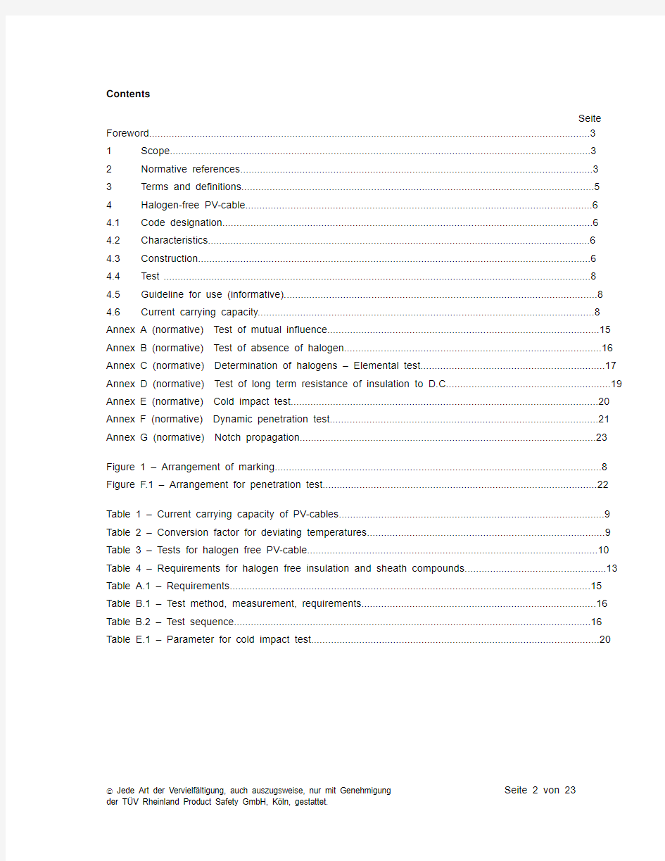
Contents
Seite Foreword (3)
1Scope (3)
2Normative references (3)
3Terms and definitions (5)
4Halogen-free PV-cable (6)
4.1Code designation (6)
4.2Characteristics (6)
4.3Construction (6)
4.4Test (8)
4.5Guideline for use (informative) (8)
4.6Current carrying capacity (8)
Annex A (normative) Test of mutual influence (15)
Annex B (normative) Test of absence of halogen (16)
Annex C (normative) Determination of halogens – Elemental test (17)
Annex D (normative) Test of long term resistance of insulation to D.C (19)
Annex E (normative) Cold impact test (20)
Annex F (normative) Dynamic penetration test (21)
Annex G (normative) Notch propagation (23)
Figure 1 – Arrangement of marking (8)
Figure F.1 – Arrangement for penetration test (22)
Table 1 – Current carrying capacity of PV-cables (9)
Table 2 – Conversion factor for deviating temperatures (9)
Table 3 – Tests for halogen free PV-cable (10)
Table 4 – Requirements for halogen free insulation and sheath compounds (13)
Table A.1 – Requirements (15)
Table B.1 – Test method, measurement, requirements (16)
Table B.2 – Test sequence (16)
Table E.1 – Parameter for cold impact test (20)
Foreword
This test specification contents the requirements listed in a manuscript of the working group AK 411.2.3 …Leitungen für PV-Systeme“ of the German committee for standardization (DKE). This manuscript is intended to be published as German pre-standard. Up to the date of publishing of the pre-standard this test-specification of TUV Rheinland will be used for test and assessment of cables for use in PV-systems (PV-cables).
1 Scope
2 PfG 1169/08.2007 applies to flexible single-core cables (cords) for use at the DC-side of photovoltaic-systems with a maximum permissible voltage of DC 1,8 kV (conductor/conductor, non earthed system). The cables are suitable for use in safety class II.
It is permitted to connect these cables as multiple-construction.
The cables are intended to operate at ambient temperature until 90°C
2 Normative references
The following referenced documents are indispensable for the application of this document. For dated references, only the edition cited applies. For undated references, the latest edition of the referenced document (including any amendments) applies.
IEC 60364-5-52, Erection of low voltage installations –Part 5: Selection and erection of electrical equipment –Chapter 52: Wiring systems
EN 50267-2-1, Common test methods for cables under fire conditions – Tests on gases evolved during combustion of materials from cables – Part 2-1: Procedures – Determination of the amount of halogen acid gas;
EN 50267-2-2, Common test methods for cables under fire conditions – Tests on gases evolved during combustion of materials from cables – Part 2-2: Procedures – Determination of degree of acidity of gases for materials by measuring pH and conductivity;
EN 50305, Railway applications – Railway rolling stock cables having special fire performance – Test methods
EN 50395, Electrical test methods for low voltage energy cables;
EN 50396, Electrical test methods for low voltage energy cables;
EN 60068-2-78, Environmental testing - Part 2-78: Tests -Test Cab: Damp heat, steady state (IEC 60068-
2-78)
EN 60216-1, Electrical insulating materials - Properties of thermal endurance - Part 1: Ageing procedures and evaluation of test results (IEC 60216-1);
EN 60216-2, Electrical insulating materials – Thermal endurance properties – Part 2: Determination of thermal endurance properties of electrical insulating materials – Choice of test criteria (IEC 60216-2);
EN 60228, Conductor of insulated cables (IEC 60228)
EN 60332-1-2, Tests on electric and optical fibre cables under fire conditions – Part 1-2: Test for vertical flame propagation for a single insulated wire or cable – Procedure for 1 kW pre-mixed flame; (IEC 60332-1-2)
EN 60684-2, Flexible insulating sleeving – Part 2: Methods of test (IEC 60684-2)
EN 60811-1-1, Insulating and sheathing materials of electric cables – Common test methods Part 1-1: General application – Measurement of thickness and overall dimensions – Test for determining the mechanical properties (IEC 60811-1-1)
EN 60811-1-2, Insulating and sheathing materials of electric and optical cables – Common test methods. Part 1-2: General application. Thermal ageing methods (IEC 60811-1-2)
EN 60811-1-3, Insulating and sheathing material of electric and optical cables – Common test methods – Part 1-3: General application – Methods for determining the density – Water absorption tests – Shrinkage test (IEC 60811-1-3)
EN 60811-1-4, Insulating and sheathing materials of electric and optical cables – Common test methods. Part 1-4: General application. Tests at low temperature. (IEC 60811-1-4)
EN 60811-2-1, Insulating and sheathing materials of electric and optical cables – Common test methods – Part 2-1: Methods specific to elastomeric compounds – Ozone resistance, hot set and mineral oil immersion tests (IEC 60811-2-1)
EN 60811-3-1, Insulating and sheathing materials of electric cables – Common test methods Part 3-1: Methods specific to PVC compounds – Pressure test at high temperature, test for resistance to cracking (IEC 60811-3-1)
HD 22.13, Rubber insulated cables of rated voltages up to and including 450/750 V Part 13: Single and multicore flexible cables, insulated and sheathed with crosslinked polymer and having low emission of smoke and corrosive gases;
HD 605, Power cables – Part 605: Additional test methods
HD 60364-7-712Electrical installations of buildings – Part 7-712: Requirements for special installations or locations – Solar photovoltaic (PV) power supply systems (IEC 60364-7-712, modified)
3 Terms and definitions
For the purposes of this document, following definitions apply.
3.1 Terms for test procedure
3.1.1
Type test (symbol T)
Tests required to be made before supplying a type of cable covered by this standard on a general commercial basis, in order to demonstrate satisfactory performance characteristics to meet the intended application. These tests are of such a nature that, after they have been made, they need not be repeated, unless changes are made in the cable materials or design or manufacturing process which might change the performance characteristics.
3.1.2
sample tests (symbol S)
Tests made on samples of completed cable or components taken from a completed cable, at a specified frequency, so as to verify that the finished product meets the specified requirements.
3.1.3
Routine tests (symbol R)
Tests made by the manufacturer on each manufactured length of cable to check that each length meets the specified requirements
3.2
Rated voltage
The rated voltage of the cable determines the construction and the tests of the cable with regard to the electrical properties.
The rated voltage is designated by two values of frequency voltage: U0/U in Volt
U0 rated power frequency voltage between conductor and earth (metallic screen of cable or ambient medium);
U rated power frequency voltage between two conductors of a multipole cable or of a system of single core cables.
The rated voltage of the cable for a given application shall be suitable for the operating conditions in the system in which the cable is used.
This requirement is applicable for both U o and U
The rated voltage between two conductors in a DC-system shall not exceed the 1,5 time value of rated voltage U of the cable, and the rated voltage between conductor and earth shall not exceed the 1,5 time value of rated voltage U o of the cable.
NOTE The operating voltage of a system may exceed is rated voltage permanent for 20%. A cable may be operated with a voltage which value is 20% higher than rated voltage under condition that the rated voltage is not less than the rated voltage of the system.
3.3
DC side
part of a PV installation from a PV cell to the DC terminals of the PV inverter
3.4
open-circuit voltage under standard test conditions U OC STC
voltage under standard test conditions across an unloaded (open) PV module, PV string, PV array, PV generator or on the DC side of the PV inverter
3.5
short-circuit current under standard test conditions I SC TC
short-circuit current of a PV module, PV string, PV array or PV generator under standard test conditions
4 Halogen free PV-cable
4.1 Code designation
PV1-F
4.2 Characteristics
4.2.1
Rated voltage
AC U 0/U 0,6/1 kV
DC 1,8 kV (conductor-conductor, non earthed system, circuit not under load).
If the cable is used in DC-systems the rated voltage between two conductors shall not exceed the 1,5 time value of rated voltage U of the cable. In with single-phase earthed DC-systems this value shall be multiplied with factor 0,5. 4.2.2
Temperature range
Ambient temperature:
–40 °C to +90 °C Max. temperature at conductor:
120 °C
The cables are intended to operate at ambient temperature until 90°C. For this a temperature index of
120°C applies to the insulation and the sheath, bas ed on EN 60216-1 (20.000h, 50% residual elongation). Note
The expected period of use is 25 years.
The permitted short-circuit-temperature refer to a period of 5s is 200°C.
4.3 Construction
4.3.1
Conductor Number of conductors: 1
The conductor shall be class 5, according to EN 60228. The single wires must be tinned. Preferred diameters: 2,5, 4, 6, 10, 16 mm 2
4.3.2
Separation layer
A separation layer of a suitable halogen free material may be applied around the conductor.
额定电压
导体工作温度
导体
绝缘
4.3.3 Insulation
The insulation shall be a suitable halogen free material applied around the conductor.
The insulation shall be extruded and shall consist of one or several adjacent adherent layers. It shall be solid and homogeneous, it must be possible to remove it without damage to the insulation itself, to the conductor and to the tin coating.
The insulation shall be smooth, consistently applied and largely circular. Compliance shall be checked by inspection and by manual test.
The wall thickness of insulation is specified by the manufacturer, but it must not fall short of the minimum value of 0,5mm.
4.3.4 Separation layer
A separation layer of a suitable halogen free material may be applied around the insulation.
4.3.5 Sheath
The core must be covered by a sheath.
The sheath around the core must be of a suitable halogen free material.
The sheath shall be extruded and shall consist of one or several adjacent adherent layers. The sheath shall be smooth and consistently applied.
The wall thickness of sheath is specified by the manufacturer, but it must not fall short of the minimum value of 0,5mm.
4.3.6 Outer diameter
The average value of the outer diameter shall be within the limits specified by the manufacturer.
4.3.7 Multiple construction
Each single-core cable in a multiple construction shall pass the requirements of this document. Each additional component in a multiple construction shall pass the requirements of this document.
4.3.8 Marking
4.3.8.1 General
The cable shall be marked as follows:
a) Trademark;
b) Code designation;
c) Rated diameter.
Marking may be by printing or by reproduction in relief on or in the sheath.
4.3.8.2 Trademark
Cables shall be provided with an indication of the manufacturer, which consist of a consecutively marking with company name or company sign or with (if trademarked) an identification number.
4.3.8.3 Code designation
Cables shall be provided with an code designation according to 4.1 applied consecutively on sheath.
4.3.8.4 Arrangement of marking
Each marking is considered as consecutive if the spacing between the end of a marking and the begin of the following identical marking does not exceed following value:
– 550mm, for marking on sheath or outer jacket.
Following figure shows an example of marking on sheath.
Figure 1 – Arrangement of marking
4.3.8.5 Durability
Printed markings shall be durable. Compliance with this requirement shall be checked by the test given in 5.1 of EN 50396.
4.3.8.6 Legibility
Each marking shall be legible.
4.4 Test
Compliance with the requirements of 4.3 shall be checked by visual inspection and tests according to table
3.
4.5 Guideline for use (informative)
Cables according to this standard are intended for use in PV-systems according to EN 60364-7-712.
4.6 Current carrying capacity
Ambient temperature: 60°C
Max. temperature at conductor: 120 °C
Table 1 – Current carrying capacity of PV-cables
Kind of installation
Rated diameter Single cable free in
air Single cable on
surfaces
To cables adjacent on
surfaces
mm2 A A A
1,5 30 29 24
2,5 41 39 33
4 5
5 52 44
6 70 6
7 57
10 98 93 79
16 132 125 107
25 176 167 142
35 218 207 176
Table 2 – Conversion factor for deviating temperatures
Ambient temperature Conversion factor
°C
Up to 60 1,00
70 0,91
80 0,82
90 0,71
100 0,58
110 0,41
Reduction factor for accumulation according to IEC 60364-5-52, Table B.52-17
Table 3 – Tests for halogen free PV-cable
No. Test Requirements
of test standard clause
5 Resistance against acid and alkaline
solution
T EN 60811-2-1 10 5.1Chemical stress
acid: N-Oxal-acid
alkaline solution: N-sodium hydroxide solution
temperature °C 23
duration h 168
5.2Tensile strength:
variation, max. % ± 30
5.3Elongation at break, min. % 100
6 Test of influence T Annex A
7 Cold impact test at –40 °C T Annex E
8 Cold bending test
Diameter of cable < 12,5 mm
T EN 60811-1-4 8.2 8.1 Test conditions:
– temperature °C –40 ± 2
– duration of conditioning h 16 EN 60811-1-4 8.2.3 8.2 Results to be obtained Absence of
cracks
9 Cold elongation test
Diameter of cable ≥ 12,5 mm
Table 3 10 Ozone resistance at complete cable T
10.1 Method B EN 50396 8.1.3
– temperature °C 40 ± 2
– relative humidity % 55 ± 5
– duration h 72
– Ozone concentration %
(by volume)
(200 ± 50) × 10–6
10.2 Results to be obtained Absence of
cracks.
11 Weathering/UV-resistance T HD 605/A1 2.4.20 11.1 Conditions:
– duration h 720
– temperature °C
(Black-Standard-temperature)
63
– relative humidity % 65
– min. power at W/m2
wavelength 300 nm to 400 nm
60 ± 2
– duration spraying/drying min 18/102
Results to be obtained Absence of
cracks.
12 Dynamic penetration test T Annex F
13 Notch propagation T Annex G
No. Test Requirements
of test standard clause
14 Shrinkage test at complete cable T EN 60811-1-3 11((sheath)) 14.1 Conditions:
– temperature °C 120
– duration h 1
– Distance L of sample mm 300
14.2 Results to be obtained:
– Maximum shrinkage. % 2
15 Test under fire conditions
15.1 Test for vertical flame propagation at complete
cable
T, S EN 60332-1-2
15.2 Assessment of halogen T, S
15.2.1 Absence of halogen Annex B 15.2.2 Determination of halogens – Annex C
Table 4 – Requirements for halogen free insulation and sheath compounds
1 2 3 4 5 6 7
Test method described in Type of compound
Ref. No. Test Unit
standard clause insulation sheath
1 Mechanical characteristics
1.1 Properties before ageing EN 60811-1-1 9.2
1.1.1 Values to be obtained for the tensile strength:
– median, min. N/mm26,5 8,0
1.1.2 Values to be obtained for the elongation at
break:
– median, min. % 125 125 1.2 Properties after ageing in oven EN 60811-1-2 8.1
1.2.1 Ageing conditions:
– temperature °C 150 ± 2 150 ± 2 – duration of treatment h 7 × 24 7 × 24 1.2.2 Values to be obtained for the tensile strength:c
– median, min. N/mm2– – – variation, max. % –30a–30a
1.2.3 Values to be obtained for the elongation at
break:c
– median, min. % – – – variation, max. % – 30a– 30a 1.3 Hot set test d EN 60811-2-1 9
1.3.1 Conditions
– Temperature °C 200± 3 200± 3 – Time under load min 15 15 – mechanical stress N/cm220 20 1.3.2 Values to be obtained
– elongation under load, max. % 100 100 – permanent elongation after cooling, max. % 25 25 1.4 Thermal endurance properties EN 60216-2
1.4.1 Conditions
Either test of elongation at break or bending test
shall be performed.
– Temperature index 120 120 – elongation at break c% 50 50 – bending test EN 50305 7.2 2 D 2 D 1.5 Cold elongation test EN 60811-1-4 8.4
1.5.1 Conditions:
– temperature °C –40 ± 2 –40 ± 2 – duration h EN 60811-1-4 8.4.4 und 8.4.5 b b 1.5.2 Values to be obtained:
– elongation at break, min. % 30 30
1 2 3 4 5 6 7
Test method described in Type of compound
Ref. No. Test Unit
standard clause insulation sheath
a No positive value for variation fixed.
b See test method in column 4 and 5.
c This test shall be performe
d at test samples of insulation and sheath compound.
d This test shall b
e performed only at cross-linked insulation and sheath compound
Test of mutual influence
A.1 Conditions
Test samples must be aged for 7 days at (135 ± 2) °C at conditions according to table 2
A.2 Requirements
After ageing the insulation and the sheath shall pass the requirements of table A.1.
Table A.1 – Requirements
Tests units insulation sheath
Tensile strength – median, min. N/mm2– –
– variation a, max. % ± 30 –30 b Elongation at break – median, min. % – –
– variation a, max. % ± 30 ± 30
a Variation: difference between the median value obtained after ageing and the median value obtained without ageing expressed as a
percentage of the latter.
b Positive tolerances are not limited.
Test of absence of halogen
B.1 Requirements of extruded materials
Insulation and sheath shall pass the requirements as follows: a) Type test
The material must be tested as described in table B.1.
Table B.1 – Test method, measurement, requirements
Test method
Measurement
requirements
1 EN 50267-2-
2 pH and conductivity pH ≥ 4,
3 und
conductivity ≤ 10 μS/mm a 2 EN 50267-2-1 Chlorine- and Bromine content, expressed in HCI ≤ 0,5 %
3a
Annex C
Halogen: Fluoride
If negative the test should be finished. No further test is necessary.
The material shall be accepted.
If positive, test of 3b shall be performed 3b
EN 60684-2
Fluoride content
≤ 0,1 %
a If discrepancies regarding conductivity appear, e.g. the recommended value is exceeded even if there is compliance with the
recommended ph-value, other test method may be applied after agreement with all participants.
b) Selection test
The material shall be tested according to test sequence of table B.2.
Table B.2 – Test sequence
Test method Measurement
Value Result
If negative the test should be finished. No further test is necessary.
The material shall be accepted. Phase 0 HD 22.13,
Annex C
Halogen: Fluoride, Chloride and Bromide
If positive continue with phase 1.
< 4,3 The material shall be revised. pH ≥ 4,3
Conductivity shall be tested. conductivity ≤ 2,5 μS/mm
The material shall be accepted. No further test is necessary.
conductivity > 10 μS/mm The material shall be revised.
Phase 1 EN 50267-2-2 conductivity (s)
> 2,5 μS/mm but ≤ 10 μS/mm Test according to EN 50267-2-1 shall be performed > 0,5 % The material shall be revised.
Phase 2 EN 50267-2-1
Chlorine- and Bromine content, expressed in HCI
≤ 0,5 % Test according to EN 60684-2 shall be performed. > 0,1 % The material shall be revised. Phase 3 EN 60684-2
Fluoride content
≤ 0,1 %
The material shall be accepted.
Determination of halogens – Elemental test
Warning
Owing to its potentially hazardous nature, the fusion operation should be carried out in a fume cupboard, using a safety screen.
C.1 Equipment
Bunsen burner
3 small/medium soda glass test tubes (approximately 50 mm x 10 mm)
Test tube holder
Evaporating basin/mortar
Wire gauze;
Funnel
Filter paper
C.2 Materials
Unknown sample
Sodium metal
Dilute nitric acid (5 %)
Aqueous silver nitrate (5 %)
Dilute ammonia (10 %)
Freshly made up zirconium-alizarin red S reagent
Glacial acetic acid
Acid/pH indicator papers
C.3 Procedure
C.3.1 Sodium fusion
Place 200 mg – 250 mg of the sample into the bottom of a small soda glass test tube. Add 10 ml of distilled/de-ionized water to the evaporating basin and place this in the fume cupboard behind the safety screen. Whilst holding the test tube firmly with the test tube holder at an angle of 45° - 60° to the vertical, introduce a piece of freshly cut, clean sodium (about the size of a small pea) (200 mg – 250 mg) into the mouth of the test tube without allowing it to come into contact with the sample. With the safety screen in place, heat the sodium gently until it melts and runs down on to the sample (there may be a vigorous reaction when the molten sodium reaches the sample if halogens are present). Heat the tube gently for about 1 min, then more strongly until the lower 20 mm of the tube glows red hot. Plunge the red hot tube into the water in the evaporating basin, immediately placing the gauze on top. (The gauze prevents any loss of material when the tube shatters on contact with the water.) Allow any non reacted sodium to react before grinding up the solution and glass. Filter, and separate the filtrate into two equal portions.
C.3.2 Chlorine and bromine
To the first portion of the filtrate, add sufficient nitric acid to make the solution acidic. Boil this solution until its total volume has been reduced by half (this is to remove any HCN or H2S, if present, which would interfere with the test). Add 1 ml silver nitrate solution; a white or yellowish-white precipitate indicates the presence of halogen (Cl, Br) in the original sample. (If the liquor is decanted, and the precipitate is white and readily soluble in dilute ammonia, then chloride is present.)
C.3.3 Fluorine
To the second portion of the filtrate, acidify with glacial acetic acid. Boil this solution until its total volume has been reduced by half. Add 2 to 3 drops freshly prepared zirconium lake reagent (equal volumes of: a) Alizarin solution: 0,05 g Alizarin Red-S in 50 ml distilled water, b) Zirconium solution: 0,05 g zirconium nitrate in 10 ml concentrated HCl diluted with 50 ml distilled water). Heat at 40 °C for 1 h. The presence of fluoride is indicated by the red/pink colouration being bleached to yellow.
Test of long term resistance of insulation to D.C.
A test sample with a length of minimum 5m shall be immersed into water containing 3 % NaCl. Further on minimum 300mm of the sample shall stick out of the water. The water-bath shall be retained for (240 ± 2) h at a high temperature of (85 ± 2) °C and a D.C.-vol tage 0,9kV shall be applied between conductor and water whereby the conductor shall be connected to the positive potential.
The current of this circuit shall be measured with a period of not more than 24h. If possible a continuous measurement shall be preferred.
The measured values shall be recorded in a time-current-curve which identifies a stable progress.
NOTE A stable progress is e.g. an increase of less than 10% of leakage current on the average for a time of 24h (This is part of the inspection based on practical experiences)
After storing the samples shall be taken out of the salt-water-solution and a voltage test according to Ref.-No. 1.2 of table 1 shall be performed. The test voltage shall be the rated voltage (U) of the cable.
Cold impact test
The cold impact test shall be performed at –40°C ac cording to clause 8.5 of EN 60811-1-4, but the mass of hammer, the mass of test probe and the height shall comply with table 2.
Table E.1 – Parameter for cold impact test
Diameter of cable (D) Mass of hammer Mass of test probe height mm g g mm
D < 15 1 000 200 100
15 < D≤ 25 1 500 200 150
D > 25 2 000 200 200
The inner and outer surface of sheath shall be inspected with normal or corrective visual faculty without magnification. Only the outer surface of the insulation shall be inspected. No cracks must be determined
《光伏发电系统专用电缆产品认证技术规范》 编制说明(申请备案稿) 1.背景 世界常规能源供应短缺危机日益严重,化石能源的大量开发利用已成为造成自然环境污染和人类生存环境恶化的主要原因之一,寻找新兴能源已成为世界热点问题。在各种新能源中,太阳能光伏发电具有无污染、可持续、总量大、分布广、应用形式多样等优点,受到世界各国的高度重视。我国光伏产业在制造水平、产业体系、技术研发等方面具有良好的发展基础,国内外市场前景总体看好。根据能源局印发的《可再生能源发展“十二五”规划》,显示我国对光伏发电今后几年的发展目标做了一个大幅的提升,到2015年中国累计光伏发电的装机容量要达到2100万千瓦,光伏产业的发展也带动配套光伏发电系统专用电缆(以下简称光伏电缆)产品的大量生产。 在光伏发电系统中,逆变器之前的直流侧(DC side)的大量直流电缆需户外敷设,环境条件恶劣,其电缆应根据具体使用场合应具备抗紫外线、臭氧、耐高低温和化学侵蚀等特殊性能。普通材质电缆在这些特殊环境下长期使用,将导致电缆护套脆化易碎,甚至绝缘层分解,而损坏电缆系统,同时增大电缆短路的风险。 因此对于光伏发电电站中户外敷设较多的光伏组件与组件之间的串联电缆、组串之间及组串至直流配电箱(汇流箱)之间的并联电缆和直流配电箱至逆变器之间的电缆,包括部分户外敷设的交流侧(AC side)电缆(逆变器之后的交流电缆),应使用光伏发电系统专用电缆(以下简称光伏电缆),该类电缆一般采用辐照交联聚烯烃绝缘和护套,需通过严苛的耐酸碱、耐湿热、耐气候以及25年热寿命等测试要求。 然而,对于该类新能源产业的光伏电缆,目前国内尚未制定发布相应的产品国家标准、行业标准或技术规范,导致行业内从产品的生产到检测、安装、使用都缺乏统一认可的指导及评定准则,国内生产企业只能参照企业标准或者国外标准来进行生产,光伏电站工程采购方也难以实现对其安全和质量进行技术要求和规范化,缺乏产品选型、设计和检验验收的依据,也一定程度上制约了整个光伏电缆产业的良性快速发展。 因此,从促进光伏电缆行业健康发展出发,为满足行业相关企业单位对光伏电缆的技术参考和考核的需求,本中心联合上海电缆研究所(国家电线电缆质量监督检验中心)、中国三峡新能源有限公司以及国内主要的光伏电缆与电缆料生产企业,在参考国外相关标准(TUV 1169 /1990/1940及UL4703标准)、国内相关标准(GB/T 12706,JB/T 10491等)以及国内企标等技术文件的基础上,起草了本技术规范,并将最终为光伏电缆产品认证提供依据,以便向社会及公众提供更多可信赖的参考依据及质量信息。2.工作过程综述 2.1技术要求制定原则 为使本技术规范能够符合生产、设计和使用单位为保障产品安全运行而对产品提出的技术要求,有助于完善对光伏电缆质量的检测,并满足科学、规范地开展认证工作的需要,在技术要求制定过程中,
光伏系统电缆设计选型与施工 在光伏电站建设过程中除主要设备,如光伏组件、逆变器、升压变压器以外,配套连接的光伏电缆材料对光伏电站的整体盈利的能力、运行的安全性、是否高效,同样起着至关重要的作用,下面就对光伏电站中常见的电缆及材料的用途和使用环境做详细的介绍。 电缆按照光伏电站的系统可分为直流电缆及交流电缆,根据用途及使用环境的不同分类如下: 一、直流电缆 (1)组件与组件之间的串联电缆。 (2)组串之间及其组串至直流配电箱(汇流箱)之间的并联电缆。 (3)直流配电箱至逆变器之间电缆。 以上电缆均为直流电缆,户外敷设较多,需防潮、防暴晒、耐寒、耐热、抗紫外线,某些特殊的环境下还需防酸碱等化学物质。 二、交流电缆 (1)逆变器至升压变压器的连接电缆。 (2)升压变压器至配电装置的连接电缆。 (3)配电装置至电网或用户的连接电缆。 此部分电缆为交流负荷电缆,户内环境敷设较多,可按照一般电力电缆选型要求选择。 三、光伏专用电缆 光伏电站中大量的直流电缆需户外敷设,环境条件恶劣,其电缆材料应根据抗紫外线、臭氧、剧烈温度变化和化学侵蚀情况而定。普通材质电缆在该种环境下长期使用,将导致电缆护套易碎,甚至会分解电缆绝缘层。这些情况会直接损坏电缆系统,同时也会增大电缆短路的风险,从中长期看,发生火灾或人员伤害的可能性也更高,大大影响系统的使用寿命。因此,在光伏电站中使用光伏专用电缆和部件是非常有必要的。光伏专用电缆和部件不仅具有最佳的耐风雨性、耐紫外线和臭氧侵蚀性,而且能承受更大范围的温度变化。 四、电缆设计选型的原则: (1)电缆的耐压值要大于系统的最高电压。如380V输出的交流电缆,要选举450/750V 的电缆 (2)光伏方阵内部和方阵之间的连接,选取的电缆额定电流为计算所得电缆中最大连续电流的1.56倍。 (3)交流负载的连接,选取的电缆额定电流为计算所得电缆中最大连续电流的1.25倍。 (4)逆变器的连接,选取的电缆额定电流为计算所得电缆中最大连续电流的1.25倍。 (5)考虑温度对电缆的性能的影响。温度越高,电缆的载流量就越少,电缆要尽量安装在通风散热的地方。 (6)考虑电压降不要超过2%。 直流回路在运行中常常受到多种不利因素的影响而造成接地,使得系统不能正常运行。如挤压、电缆制造不良、绝缘材料不合格、绝缘性能低、直流系统绝缘老化、或存在某些损伤缺陷均可引起接地或成为一种接地隐患。另外户外环境小动物侵入或撕咬也会造成直流接地故障。因此在这种情况下一般使用铠装、带防鼠剂功能护套的电缆。 分布式光伏常用逆变器电缆选择:
电力电缆截面的选择 电力电缆截面 1 电力电缆缆芯截面选择的基本要求。 1.1 最大工作电流作用下的缆芯温度,不得超过按电缆使用寿命确定的允许值。持续工作回路的缆芯工作温度,应符合附录A的规定。 1.2 最大短路电流作用时间产生的热效应,应满足热稳定条件。对非熔断器保护的回路,满足热稳定条件可按短路电流作用下缆芯温度不超过附录A所列允许值。 1.3 连接回路在最大工作电流作用下的电压降,不得超过该回路允许值。 1.4 较长距离的大电流回路或35kV以上高压电缆,当符合上述条款时,宜选择经济截面,可按“年费用支出最小”原则。 1.5 铝芯电缆截面,不宜小于4。 1.6 水下电缆敷设当需缆芯承受拉力且较合理时,可按抗拉要求选用截面。 2 对10kV及以下常用电缆按持续工作电流确定允许最小缆芯截面时,宜满足附录B电缆允许持续载流量(建议性基础值)、以及由附录C按下列使用条件差异影响计入校正系数所确定的允许载流量。 (1)环境温度差异。 (2)直埋敷设时土壤热阻系数差异。 (3)电缆多根并列的影响。 (4)户外架空敷设无遮阳时的日照影响。
3 不属于本规范第2条规定的其他情况下,电缆按持续工作电流确定允许最小缆芯截面时,应经计算或测试验证,且计算内容或参数选择应符合下列规定: (1)中频供电回路使用非同轴电缆,应计入非工频情况下集肤效应和邻近效应增大损耗发热的影响。 (2)单芯高压电缆以交叉互联接地当单元系统中三个区段不等长时,应计入金属护层的附加损耗发热影响。 (3)敷设于塑料保护管中的电缆,应计入热阻影响;排管中不同孔位的电缆还应分别计入互热因素的影响。 (4)敷设于封闭、半封闭或透气式耐火槽盒中的电缆,应计入包含该型材质及其盒体厚度、尺寸等因素对热阻增大的影响。 (5)施加在电缆上的防火涂料、包带等覆盖层厚度大于1.50mm时,应计入其热阻影响。 (6)沟内电缆埋砂且无经常性水份补充时,应按砂质情况选取大于2.0℃·m/W 的热阻系数计入对电缆热阻增大的影响。 4 缆芯工作温度大于70℃的电缆,计算持续允许载流量时,尚应符合下列规定: (1)数量较多的该类电缆敷设于未装机械通风的隧道、竖井时,应计入对环境温升的影响。 (2)电缆直埋敷设在干燥或潮湿土壤中,除实施换土处理等能避免水份迁移的情况外,土壤热阻系数宜选取不小于2.0℃·m/W。 5 确定电缆持续允许载流量的环境温度,应按使用地区的气象温度多年平均值,并计入实际环境的温升影响。宜符合表5的规定: 电缆持续允许载流量的环境温度确定(℃)表5
电缆招标技术要求一、货物需求一览表
二、技术规格 1、需求货物: 交联聚氯乙烯绝缘电力电缆 阻燃交联聚氯乙烯绝缘电力电缆 阻燃变频交联聚氯乙烯绝缘电力电缆 变频交联聚氯乙烯绝缘电力电缆 交联聚乙烯绝缘聚氯乙烯护套电力电缆 交联聚乙烯绝缘聚氯乙烯护套双钢带铠装聚氯乙烯外护套电力电缆 聚氯乙烯绝缘电线电缆 聚氯乙烯绝缘聚氯乙烯护套控制软电缆 聚氯乙烯绝缘聚氯乙烯护套编织屏蔽控制软电缆 聚乙烯绝缘聚氯乙烯护套铜带绕包对屏集散型仪表信号软电缆 聚乙烯绝缘聚氯乙烯护套铜带绕包对屏集散型仪表信号电缆 补偿电缆 氟塑料绝缘阻燃聚氯乙烯护套铜丝编织分屏、总屏计算机软电缆 交联聚乙烯绝缘聚氯乙烯护套铜丝编织屏蔽变频器用电力电缆 阻燃交联聚乙烯绝缘聚氯乙烯护套铜丝编织变频电力电缆 硅橡胶绝缘硅橡胶护套安装线 硅橡胶绝缘和护套镀锡铜丝编织移动用扁平软电缆 阻燃氟塑料绝缘聚氯乙烯护套控制软电缆 阻燃氟塑料绝缘铜丝编织屏蔽聚氯乙烯护套控制软电缆 阻燃硅橡胶绝缘硅橡胶护套安装线 2、交货地点: 焦作千业水泥有限责任公司二期4500t/d熟料水泥生产线安装现场。 3、交货期: 30 天 4、供货范围: 4 1各种电缆具体规格见技术要求5,供货范围为满足技术参数要求的全部部件,保证设备能够长期、安全、正常运转,并达到下面所要求的技术参数所必须的货物、随机附件、专用工具。详细范围以供方提供的总图、分总图图纸为准;详细内容填入下表。
4.2要求投标方根据标段分别报价,并分别报出各规格的单价、总价。 4.3投标方必须满足但不仅限于第5款技术参数中所规定内容。 4.4中标方应提供的资料,包括但不限于以下内容: 产品合格证、装箱清单、润滑油牌号清单、原材料合格证(产地证明)、安装使用维护说明书。 5、技术要求:
国家电网公司集中规模招标采购 技术规范专用部分 阿城电业局2016年技改、大修工程 10KV电力电缆 二○一六年四月
目录 1 技术参数和性能要求 (3) 1.1 8.7/15kV电缆结构及技术参数 (3) 1.2 电缆非电气技术参数 (3) 2 项目需求部分 (6) 2.1货物需求及供货范围一览表 (6) 2.2 必备的备品备件、专用工具和仪器仪表需求表 (6) 2.3 投标人应提供的有关资料 (6) 2.4 工程概况 (20) 2.5 使用条件 (20) 2.6 项目单位技术差异表 (22) 3投标人响应部分 (22) 3.1 技术偏差 (22) 3.2 投标产品的销售及运行业绩表 (22) 3.3 主要原材料产地表 (23) 3.4 推荐的备品备件、专用工具和仪器仪表供货表 (23)
1 技术参数和性能要求 投标人应认真填写表1~表3中投标人保证值,不能空格,也不能以“响应”两字代替。 不允许改动招标人要求值。如有偏差,请填写表9 技术偏差表。 1.1 8.7/15kV电缆结构及技术参数 8.7/15kV电缆结构及技术参数见表1~表2。 1.2 电缆非电气技术参数 电缆非电气技术参数见表3。 表1 8.7/15kV电缆结构参数表 序 号 项目单位标准参数值投标人保证值备注1 电缆型号/ ZC-YJLV22-8.7/15KV-3*240 2 铝导体 材料/ 铝铝 材料生产厂及牌号/ 太原铝厂太原铝厂 芯数×截面积3×240 3×240 结构形式圆形紧压圆形紧压 最少单线根数根34 34 对应240截面单线直径mm 项目单位填写 3.03 对应240截面导体外径mm 项目单位填写18.3 对应240截面紧压系数≥0.9 ≥0.9 3 挤包导 体屏蔽 层 材料、生产厂及牌号半导电料半导电料平均厚度mm 0.8mm 0.8mm 最小厚度mm 0.7mm 0.7mm 外径mm 项目单位填写19.9 4 绝缘 材料、生产厂及牌号/ XLPE XLPE 平均厚度不小于标称厚 度t mm 4.5 4.5 最薄点厚度不小于mm 4.1 4.1 偏心度% 10% 10% 5 挤包绝 缘屏蔽 层 标称厚度mm 0.8mm 0.8mm 最小厚度mm 0.6mm 0.6mm 外径mm 项目单位填写30.5 6 金属屏 蔽 铜带层数/ 1 1 铜带厚度mm 0.10 0.10 搭盖率不小于% 20 20 20℃时最大直流电阻Ω/km / / 7 填充层填充材料/ 非吸湿性聚 丙烯撕裂薄 膜 非吸湿性聚丙 烯撕裂薄膜 8 隔离套挤包材料/ 项目单位填写半导电料
太阳能光伏电缆标准 Document number:NOCG-YUNOO-BUYTT-UU986-1986UT
一、应用范围 特性:低烟无卤、优良的耐寒、耐紫外线、耐臭氧和耐气候性。阻燃、耐切痕、耐穿透。线缆保护级别Ⅱ级。 环境温度:-40℃~+90℃;导体最高温度:120℃(允许5s内短路温度200℃); 额定电压:1kV 设计寿命:25年 二、结构 导体:IEC60228 5类绞合镀锡铜线PV1-F 、4、6、10mm2 绝缘:交联低烟无卤阻燃聚烯烃双层绝缘厚度﹥,并符合客户给定的限值。 护套:交联低烟无卤阻燃聚烯烃厚度﹥ 采用150℃无卤阻燃光伏电缆辐照绝缘料(因为最高温度为120℃,必须高于它),是以无卤无毒改性聚烯烃树脂为主要原料,加入无卤无毒阻燃剂、热稳定剂、消烟剂、防霉剂等助剂,不含卤素(欧洲特别强调)、重金属、磷元素。且符合ROHS,浸水后绝缘电阻变化小。 PV1-F太阳能光伏发电设备用电缆,是根据光伏发电设备所处的特殊环 境条件设计的,主要适用于直流电压端,发电设备的引出链接和组件
间汇流连接,最高电压的光伏发电设备系统。PHOTOVOLTAIC EQUIPMENT HALOGEN-FREE PV1-F CABLE应用标准:2 Pfg 1169/产品规格:、 mm2、4 mm2、6 mm2、10 mm2 产品用途:用于太阳能光伏系统连接,可适用于昼夜温差大的沙漠和有盐雾潮湿的沿海以及高原辐射强的地区。 产品特性:工作温度–40℃~90℃弯曲半径≤5D短路温度电缆短路时(最长持续的时间不超过5S)导体最高温度不超过250℃耐气候性符合UV(UVISO 4892-2A)耐臭氧符合IEC60811-2-1阻燃特性单根垂直燃烧(符合IEC60332-1)具有优异的耐酸碱性和耐湿热性
广东电网公司城乡配电网 建设与改造工程 [定期协议采购] 0.6/1kV交联聚乙烯(或聚氯乙烯)绝缘 电力电缆 招标文件(技术部分) 二OO六年三月
总目录 一 0.6/1kV交联聚乙烯(或聚氯乙烯)绝缘电力电缆招标 文件 (1) 0.6/1kV交联聚乙烯(或聚氯乙烯)绝缘电力电缆招标文件(技术部分) 二00六年三月 目录 1.总则 (3) 1.1投标须知 (3) 1.2投标人应提供的文件………………………………………………….3 2.应遵循的主要标准 (3) 3.使用条件 (4)
3.1运行条件 (4) 3.2环境条件 (4) 3.3敷设条件 (4) 3.4运行要求 (4) 4.技术要求 (4) 4.1导体 (4) 4.2绝缘 (4) 4.3铠装 (5) 4.4 外护层 (5) 4.5成品电缆标志 (5) 4.6电缆盘………………………………………………………………….5
5.试验 (6) 6.包装储运 (7) 7.供货范围 (7) 8.投标厂商应提供的技术文件 (14) 9.附表 (15)
0.6/1kV交联聚乙烯(或聚氯乙烯)绝缘电力电缆 招标书(技术部分) 1.总则 1.1 投标须知 1.1.1 投标人应仔细阅读招标书。投标人所提供的产品必须满足招标书中提出的所有要求。 1.1.2 投标人必须以书面形式对招标书全部条文作出响应,否则视为废标。 1.1.3 招标书中所提出的技术指标与投标书中响应的技术指标不一致时,按按两者之中较高的执行。 1.1.4 招标书经投标人书面确认后,作为订货合同的技术附件,与合同正文具有同等法律效力。 1.2投标人应提供的文件 1.2.1 投标人应提供与本招标书同类型电缆的型式试验报告。型式试验报告应是通过国
电气线路敷设中如何正确选择线缆的种类 线缆的敷设,一般取决线缆的特性,体现线缆特性的是线缆的型号。首先我们介绍下电气线路常用线缆型号的含义; 一、电气线路常用线缆型号 1、普通电线电缆型号 普通电线电缆、不具有阻燃、耐火、无卤及低烟的特性 额定电压 导体规格 无者:非铠表电缆 22:钢带铠表 32:钢丝铠表 无者:为无护套 V:聚氯乙烯护套 Y:聚烯烃护套 导体 无者:铜导体 L:铝导体 绝缘材料 V:聚氯乙烯 YJ:交联聚乙烯 用途: 无:电力电缆 B:布线 K:控制电缆 如:BV——就是聚氯乙烯绝缘的铜芯电线 BW——就是聚氯乙烯护套聚氯乙烯绝缘铜芯电线 YJV——交联聚乙烯绝缘、聚氯乙烯护套无铠装铜芯电力电缆 YJV22——交联聚乙烯绝缘、聚氯乙烯护套钢带铠装铜芯电力电缆 KYJV22——交联聚乙烯绝缘、聚氯乙烯护套钢带铠装铜芯控制电缆
2、阻燃线缆的型号 火灾发生时,阻止或延缓火焰在电缆上蔓延,需用阻燃型线缆。这种线缆通常是在上述普通线缆的绝缘和护套材料中加阻燃剂、或者对材料进行一种处理。一般用“Z”表示,它分有A、B、C、D四个阻燃等级,按照阻燃等级,在普通线缆的型号前加ZA或ZB、ZC、ZD。 对于电缆:特级防火等级的建筑物,应选A级阻燃的电缆 一级防火等级的建筑物,应选B级阻燃的电缆 二、三级防火等级的建筑物,应选C级阻燃的电缆 对于导线:特级防火等级的建筑物,电线截石50 mm2以上选B级阻燃的电线特级防火等级的建筑物,电线截石35 mm2以下选C级阻燃的电线 一级防火等级的建筑物,电线截石50 mm2以上选C级阻燃的电线 一级防火等级的建筑物,电线截石35 mm2以下选D级阻燃的电线 二、三级防火等级的建筑物,均选D级阻燃等级的电线 另外在防火封堵通道中敷设电缆时,还要根据电缆的非金属含量进行电缆阻燃等级的选 择,非金属含量是用升/每米为单位表示的。 非金属含量在7-14 L/m以上,选A级阻燃等级的电缆 非金属含量在3.5-7 L /m以上,选B级阻燃等级的电缆 非金属含量在1.5-3.5 L /m以上,选C级阻燃等级的电缆 还有一种电缆、无卤低烟电缆,这种电缆的外护套是聚烯烃,聚烯烃不含卤,发烟率很低,火中释放的毒性指数仅为聚氯乙烯的5%。也有上述的四个阻燃等级,电缆型号为:WDZ(A、B、C)—YJY。 3、耐火电线电缆型号 火灾发生时,为保证重要设备能正常工作,所以需要用具有耐火特性的线缆,通常这种线缆是在铜导体上缠包云母耐火带,保证线缆持续通电一段时间,它的实验数据是一般供火温放在750oC~800 oC可以维持90分。 耐火线缆可分为:阻燃耐火线缆和非阻燃耐火线缆,这就是看它的非金属材料(绝缘和护套)是不是具有阻燃性能。穿耐火金属管敷设的耐火线缆是不需要有阻燃特性的,而在实际工程中,电线、电缆往往是成束敷设的,考虑到非阻燃
PV-电缆(光伏组件用电 缆) 1、技术规范 PV-电缆(光伏组件用电缆)目前尚无国家或行业标准,本试验技术规范所涉及到的要求来自于德国标准化委员会PV-系统用电线K411.2.3工作组的初稿。 这个初稿将作为德国国家标准报批稿进行发布。 德国莱茵TUV(上海)将用此技术规范对PV-电缆的性能进行检测和评估。 在德国莱茵TUV公司内部此技术规范的文件编号为2PfG 1169/08.2007。 2、使用范围 2PfG 1169/08.2007适用于最高允许1.8kV(线芯对线芯,非接地系统)直流电压、在光伏系统中CD侧使用的单芯软电缆(电线)。 该产品适合于Ⅱ类安全等级下使用。 电缆运行的环境温度最高到90℃。 电缆可以多根并联使用。 3、特殊名词术语 PV 系统(photovoltaic system):光伏系统(太阳能系统)。 DC侧(DC side):光伏装置中从光伏电池到光伏换流器直流端子之间的部分。 标准试验条件下的开路电压(UOC STC):在标准试验条件下,未加载(开路)的光伏组件、光伏电线、光伏列阵、光伏发电机或光伏换流器直流侧的电压。 标准试验条件下的短路电流(ISC TC):在标准试验条件下,光伏组件、光伏电线、光伏列阵或光伏发电机的短路电流。 4、无卤PV-电缆的基本信息 4.1电缆型号 PV1-F 4.2电缆特性 ●额定电压: AC U0/U=0.6/1kV
DC 1.8kV(线芯对线芯,非接地系统,没有负载下的回路) 如果电缆使用在直流系统中,其导体间的额定电压应不大于电缆AC额定值U的1.5倍。在单相接地直流系统中,此数值应乘以0.5的系数。 ●温度范围: 环境温度: -40℃到+90℃ 导体最高工作温度:120℃ 电缆运行的环境温度最高到90℃。依据EN60216-1标准进行考核,其绝缘和护套的温度指数是120℃。 期望使用寿命是25年 5秒钟的短路温度是200℃ 4.3电缆结构 ●导体 导体芯数: 1 导体是EN60228(IEC60228、GB/T3956)中的第5类导体,而且必须是镀锡的。 ●导体的截面 1.5, 2.5,4,6,10,16,25,35mm2。 ●导体隔离层 在导体周围可以使用一层合适的无卤材料作为隔离层。 ●绝缘 绝缘应是挤出型的无卤材料,应是一层或紧密粘附着的几层组成。绝缘应是实心且材质均匀,在剥离绝缘时必须尽可能不要损伤绝缘本身、导体和镀锡层。 绝缘厚度由生产商规定,但最小值必须≥0.5mm。 建议的绝缘厚度 标称截面(mm2) 1.5 2.5 4 6 25 35
中国南方电网有限责任公司电缆沟盖板标准技术标书第1页/ 共13页 电缆沟盖板标准技术标书 (钢纤维混凝土盖板) 编号:20110xxxxxxx 中国南方电网有限责任公司 2011年10月
目录 1 总则 (1) 2 工作范围 (2) 2.1 工程概况 (2) 2.2 范围和界限 (2) 2.3 服务范围 (2) 3 应遵循的主要标准 (4) 4 技术要求 (5) 4.1原材料 (5) 4.2 承载等级 (5) 4.3 颜色要求 (5) 4.4 质量要求 (6) 4.5 几何尺寸及允许偏差 (6) 5 试验及验收 (6) 5.1 概述 (6) 5.2 试验 (7) 5.3 验收 (7) 6 技术文件要求 (8) 7 监造、标识及包装、运输及贮存、技术服务及质量保证 (8) 7.1 监造 (8) 7.2 标识及包装 (8) 7.3 运输及贮存 (9) 7.4 技术服务 (9) 7.5 质量保证 (10) 8 盖板开启工具 (10) 9 主要材料来源 (10) 10产品技术参数和性能要求响应表 (11) 11技术差异表 (11) 12投标方需说明的其他问题 (12) 附录A:电缆沟钢纤维混凝土盖板抗裂性及承载能力试验方法 附图1:电缆沟钢纤维混凝土盖板(行人) 附图2:电缆沟钢纤维混凝土盖板(行车)
1 总则 1.1本技术标书适用于中国南方电网公司所属配网工程户外电缆沟钢纤维混凝土盖板。技术标书提出了电缆沟钢纤维混凝土盖板的规格型号、承载要求、质量检验、包装及运输、盖板开启、质量保证等方面应执行的技术标准及要求。 1.2 本技术标书提出的是最低限度的技术要求,并未对一切技术细节作出规定,也未充分引述有关标准和规范的条文,投标方应提供符合本技术规范引用标准的最新版本标准和本招标文件技术要求的全新产品,如果所引用的标准之间不一致或本招标文件所使用的标准如与投标方所执行的标准不一致时,按要求较高的标准执行。 1.3 如果投标方没有以书面形式对本技术标书的条文提出异议,则意味着投标方提供的设备完全符合本技术标书的要求。如有异议,不管是多么微小,都应在报价书中以“对技术标书的意见和同技术标书的差异”为标题的专门章节中加以详细描述。 1.4 本技术标书经招、投标双方确认后作为订货合同的技术附件,与合同正文具有同等的法律效力。 1.5 本技术标书未尽事宜,由招、投标双方协商确定。 1.6 投标方在应标技术标书中应如实反映应标产品与本技术标书的技术差异。如果投标方没有提出技术差异,而在执行合同的过程中,招标方发现投标方提供的产品与本招标技术标书的条文存在差异,招标方有权利要求退货,并将对下一批次的评标工作有不同程度的影响。 1.7 投标方应在应标技术部分按本技术标书的要求如实详细的填写应标设备的标准配置表,并在应标商务部分按此标准配置进行报价,如发现二者有矛盾之处,将对评标工作有不同程度的影响。 1.8 投标方应充分理解本技术标书并按本技术标书的具体条款、格式要求填写应标的技术文件,如发现应标的技术文件条款、格式不符合本技术标书的要求,则认为应标不严肃,在评标时将有不同程度的扣分。 1.9 投标方应根据现行国家及行业标准、业主批准的施工图及有关技术文件,按计划工期要求进行。投标方提供的产品应是全新的。不能因施工图和技术文件的遗漏、疏忽和不明确而解脱投标方提供符合有关标准要求的产品和工作质量的责任。投标方若发现技术文件有不正确之处,必须通知业主,在差异问题未纠正之前仍进行的任何工作,应由投标方负责。
中国南方电网10kV电力电缆标准技术标书 中国南方电网10kV电力电缆标准技术标书 目录 1总则 (1) 2工作范畴 (1) 2.1范畴和界限 (1) 2.2 服务范畴 (2) 3 应遵循的要紧标准 (2) 4使用条件 (4) 4.1 正常使用条件 (4) 4.2系统条件要求 (5) 4.3敷设条件 (5) 5 技术要求 (6) 5.1 差不多参数(参数见附录) (6) 5.2 ★设计和结构要求 (6) 6试验 (10) 6.1 型式试验 (10)
6.2 现场试验 (11) 7 产品对环境的阻碍 (11) 8 企业VI标识 (11) 9 技术文件要求 (11) 9.1 图纸资料 (12) 9.1.1长期载流量运算书 (12) 9.1.2短时过负荷曲线 (12) 9.1.3导体和金属屏蔽热稳固运算书 (12) 9.1.4承诺弯曲半径 (12) 9.1.5敷设时弯曲半径 (12) 9.1.6运行时弯曲半径 (12) 9.1.7导体承诺最大拉力 (12) 9.1.8电气性能参数(导体直流电阻、外护套体积电阻率、绝缘的tgδ、 电容值、正序阻抗、零序阻抗) (12) 9.2 技术服务 (12) 9.3 设计联络 (12) 10 监造、包装、运输、安装及质量保证 (13) 10.1监造 13 10.2包装 13
11 设备技术参数和性能要求响应表 (14) 12 备品备件及专用工具 (16) 12.1必备的备品备件、专用工具和仪器外表 (16) 12.2 举荐的备品备件、专用工具和仪器外表 (16) 13 要紧元器件来源 (16) 14 LCC数据文件 (16) 15 技术差异表 (17) 16 投标方需讲明的其他咨询题 (17) 17 附录 (18) 附录A:常用电力电缆导体的最高承诺温度 (18) 附录B:电缆的绝缘水平(单位:kV) (18) 附录C:单芯XLPE电缆8.7/10 kV、8.7/15 kV、 YJV、YJLV 结构参数 (18) 附录D:单芯XLPE电缆8.7/10 kV、8.7/15 kV、 YJV、YJLV 电气参数 (18) 附录E:单芯XLPE电缆8.7/10 kV、8.7/15 kV、 YJV、YJLV 载流量 (20) 附录F:三芯XLPE电缆8.7/10 kV、8.7/15 kV、 YJV、YJLV 结构参数 (21) 附录H:三芯XLPE电缆8.7/10 kV、8.7/15 kV、 YJV、YJLV 电气参数 (22) 附录I:三芯XLPE电缆8.7/10 kV、8.7/15 kV、 YJV、YJLV 载流量 (23) 附录J: 10kV及以下电缆在不同环境温度时的载流量校正系数 (23) 18附表 (24)
光伏电缆技术极其标准的发展 所有的太阳能电池,均产生直流电并需要转换交流电。具有一定容量的光电源,需要许多千个单元模块组成,并将每一个单元模块有规则的连接起来,可想而知PV电缆结构中包括很多的绝缘细线。初期研究光伏电池,主要精力是对元件及其组合方面,目前对于PV电缆的研究也提到了日程。近十年来,全球光能发电市场高速增长,而光伏电缆仍没有国际标准,因此可借鉴的标准和试验,需加以调整,如寿命循环试验等,尤其应当注意的是电缆长期暴露在强烈紫外线下的老化问题。 光伏电池由大到小,一般居民屋顶的小型PV为几千瓦峰值 (kWp-Kilowatt peak),工业用的中型PV为几兆瓦峰值(MWp),大型发电场PV达2千兆瓦峰值(2GWp)。2008年全球新安装系统的PV市场为5.6 GW,大多数人预测每年约8~10GW的能力。PV用电缆通常考虑只在系统的直流部分,不包括栅极接线、系统控制电缆及其他连接电线等。PV电缆与PV安装容量的关系大致如下:1 MW约相当配套40~60km PV cable,这与晶体和薄膜组件的排列和数量直接相关,其连接原理见图1,图中未画出变流器。
图1 细线电缆和模块电缆与模块连接原理 PV电缆长期暴露在阳光下,或者长期浸泡在水中,还有环境温度的急剧变化,因此用户对于电缆的寿命问题即为关注。因为没有国际标准(如IEC标准),制造者也觉得缺乏依据,所以PV电缆在发展过程中,对其质量和寿命问题出现了争论,但大多数专家持赞同意见。 由UL出版和发行的《光电伏打电线的调查大纲》UL-4703(及其相关标准和基准);另外由TüV(德国技术上检验局)印刷的《在光伏系统使用的电缆要求》2Pfg-1169"(及其相关的标准和基准),成为目前主要的参考文件。将来也许会成为公认的标准。 电缆导体由很细的镀锡组成,符合IEC 60228 class,截面大都为4.00 mm2 and 6.00 mm2,分别由56根单线和84根单线组成;绝缘层护套符合TüV和UL要求,热塑或交联惨了均可使用,这些属于常规规定,绝缘厚度曲0.5 mm。
电缆招标技术要求 Prepared on 22 November 2020
电缆招标技术要求一、货物需求一览表
二、技术规格 1、需求货物: 交联聚氯乙烯绝缘电力电缆 阻燃交联聚氯乙烯绝缘电力电缆 阻燃变频交联聚氯乙烯绝缘电力电缆 变频交联聚氯乙烯绝缘电力电缆 交联聚乙烯绝缘聚氯乙烯护套电力电缆 交联聚乙烯绝缘聚氯乙烯护套双钢带铠装聚氯乙烯外护套电力电缆 聚氯乙烯绝缘电线电缆 聚氯乙烯绝缘聚氯乙烯护套控制软电缆 聚氯乙烯绝缘聚氯乙烯护套编织屏蔽控制软电缆 聚乙烯绝缘聚氯乙烯护套铜带绕包对屏集散型仪表信号软电缆 聚乙烯绝缘聚氯乙烯护套铜带绕包对屏集散型仪表信号电缆 补偿电缆 氟塑料绝缘阻燃聚氯乙烯护套铜丝编织分屏、总屏计算机软电缆 交联聚乙烯绝缘聚氯乙烯护套铜丝编织屏蔽变频器用电力电缆 阻燃交联聚乙烯绝缘聚氯乙烯护套铜丝编织变频电力电缆 硅橡胶绝缘硅橡胶护套安装线 硅橡胶绝缘和护套镀锡铜丝编织移动用扁平软电缆 阻燃氟塑料绝缘聚氯乙烯护套控制软电缆 阻燃氟塑料绝缘铜丝编织屏蔽聚氯乙烯护套控制软电缆 阻燃硅橡胶绝缘硅橡胶护套安装线 2、交货地点: 焦作千业水泥有限责任公司二期4500t/d熟料水泥生产线安装现场。 3、交货期: 30 天 4、供货范围: 各种电缆具体规格见技术要求5,供货范围为满足技术参数要求的全部部件,保证设备能够长期、安全、正常运转,并达到下面所要求的技术参数所必须的货物、随机附
要求投标方根据标段分别报价,并分别报出各规格的单价、总价。 投标方必须满足但不仅限于第5款技术参数中所规定内容。 中标方应提供的资料,包括但不限于以下内容: 产品合格证、装箱清单、润滑油牌号清单、原材料合格证(产地证明)、安装使 用维护说明书。 5、技术要求:
一、应用范围 特性:低烟无卤、优良的耐寒、耐紫外线、耐臭氧和耐气候性。阻燃、耐切痕、耐穿透。线缆保护级别Ⅱ级。 环境温度:-40℃~+90℃;导体最高温度:120℃(允许5s内短路温度200℃); 额定电压:AC0.6/1kV DC1.8kV 设计寿命:25年 二、结构 导体:IEC60228 5类绞合镀锡铜线PV1-F 2.5、4、6、 10mm2 绝缘:交联低烟无卤阻燃聚烯烃双层绝缘厚度﹥0.5mm,并符合客户给定的限值。护套:交联低烟无卤阻燃聚烯烃厚度﹥0.5mm 采用150℃无卤阻燃光伏电缆辐照绝缘料(因为最高温度为120℃,必须高于它),是以无卤无毒改性聚烯烃树脂为主要原料,加入无卤无毒阻燃剂、热稳定剂、消烟剂、防霉剂等助剂,不含卤素(欧洲特别强调)、重金属、磷元素。且符合ROHS,浸水后绝缘电阻变化小。 下表为典型结构: PV1-F太阳能光伏发电设备用电缆,是根据光伏发电设备所处的特殊环境条件设计的,主要适用于直流电压端,发电设备的引出链接和组件间汇流连接,最高电压DC1.8kV的光伏发电设备系统。PHOTOVOLTAIC
EQUIPMENT HALOGEN-FREE PV1-F CABLE应用标准:2 Pfg 1169/08.2007产品规格:1.5mm2、2.5 mm2、4 mm2、6 mm2、10 mm2
产品用途:用于太阳能光伏系统连接,可适用于昼夜温差大的沙漠和有盐雾潮湿的沿海以及高原辐射强的地区。 产品特性:工作温度–40℃~90℃弯曲半径≤5D短路温度电缆短路时(最长持续的时间不超过5S)导体最高温度不超过250℃耐气候性符合UV(UVISO 4892-2A)耐臭氧符合IEC60811-2-1阻燃特性单根垂直燃烧(符合IEC60332-1)具有优异的耐酸碱性和耐湿热性 (资料素材和资料部分来自网络,供参考。可复制、编制,期待你的好评与关注)
电缆采购工程技术要求及参数文件 本技术要求所提出的技术指标是最低限度的技术要求,供货商应保证提供符合本技术条件书和相关的国际国内标准的优质产品, 所有提供的货物应遵照适用的最新版IEC标准和中国GB标准,以及国际单位制(SI)。对国家有关安全、环保等强制性标准,必须满足其要求。本要求所使用的标准如与供货方所执行的标准不一致时, 按较高标准执行。 一、采购内容及清单 1.范围: 包括本工程所包含的各种型号的中、低压电力电缆和电线。 2.清单(见附件) 二、基本要求 1.一般规定 1)凡在实施强制性产品认证的产品目录内的产品必须具有3C认证; 2)材料、制造和测试应执行最新版本的中国标准; 3)提供具有国家级权威部门出具的型式试验报告。 4)提供包装、运送、并卸货至指定的现场。 5)备品备件清单和必需操作工具。 6)负责现场指导安装、测试及通过质量验收。 2.环境使用条件 所有设备及材料应满足中国山西省朔州市的环境使用条件;
1)海拨高度:≤1500M 2)环境湿度: 日平均≤95%,月平均≤90%,(20℃以下为90%) 3)最高温度: +50℃ 4)最低温度: -25℃ 5)24小时内其平均温度不超过: +35℃ 6)地震烈度: 不超过7度 三、低压电力电缆和控制电缆主要技术指标 1.主要型号: 1KV铠装铝合金电力电缆MELHSC-1KV 1KV铠装铝合金阻燃电力电缆ZBN-MELHSC-1KV 1KV交联聚氯乙烯绝缘电力电缆YJV-1KV 耐火聚氯乙烯绝缘聚氯乙烯护套电缆NHBVV 聚氯乙烯绝缘聚氯乙烯护套电缆BVV 2.使用条件: 额定电压:0.6/1kv、额定频率:50hz 敷设条件:桥架、竖井、穿管等各种敷设方式。 导体长期工作温度:90℃。 导体短路温度:短路温度不超过280℃,短路最长延续时间为5秒 电线、电缆使用寿命:不少于40年 3.标准及依据 制造、试验和验收应符合但不限于如下标准(以国家现行最新为准):JGJ 16-2008 《民用建筑电气设计规范》 GB/T5023-2008 《额定电压450V/750 V 及以下聚氯乙烯绝缘电缆》GB2951.19《电线电缆燃烧试验方法》 GB2951.23 《电线电缆弯曲试验方法》 GB/T2952-2008《电缆外护套》 GB/T3956-2008《电缆的导体》 GB/T6995-2008《电线电缆标识标志方法》 GB/T2951.1~10-2008《电缆绝缘和护套材料通用试验方法》
光伏系统中电缆的选取设计方法 一、光伏系统中电缆的选择主要考虑如下因素: 1、电缆的绝缘性能。 2、电缆的耐热阻燃性能。 3、电缆的防潮,防光。 4、电缆的敷设方式。 5、电缆芯的类型(铜芯,铝芯>。 6、电缆的大小规格。 二、光伏系统中不同的部件之间的连接,因为环境和要求的不同,选择的电缆也不相同。以下分别列出不同连接部分的技术要求: 1>元件与元件之间的连接 必须进行UL测试,耐热90℃,防酸,防化学物质,防潮,防曝晒。 2>方阵内部和方阵之间的连接 可以露天或者埋在地下,要求防潮、防曝晒。建议穿管安装,导管必须耐热90℃。 3>蓄电池和逆变器之间的接线 可以使用通过UL测试的多股软线,或者使用通过UL测试的电焊机电缆。 4>室内接线(环境干燥> 可以使用较短的直流连线。 三、电缆大小规格设计,必须遵循以下原则: 1>蓄电池到室内设备的短距离直流连接,选取电缆的额定电流为计算电缆连续电流的1.25倍。 2>交流负载的连接,选取的电缆额定电流为计算所得电缆中最大连续电流的1.25倍。 3>逆变器的连接,选取的电缆额定电流为计算所得电缆中最大连续电流的1.25倍。 4>方阵内部和方阵之间的连接,选取的电缆额定电流为计算所得电缆中最大连续电流的1.56倍。 5>考虑温度对电缆的性能的影响。 6>考虑电压降不要超过2%。
7>适当的电缆尺径选取基于两个因素,电流强度与电路电压损失。完整的计算公式为:线损 = 电流×电路总线长×线缆电压因子式中线缆电压因子可由电缆制造商处获得。 太阳能跟踪器 太阳能跟踪器是保持太阳能电池板随时正对太阳,让太阳光的光线随时垂直照射太阳能电池板的动力装置,采用太阳能跟踪器能显著提高太阳能光伏组件的发电效率。 目前世界上通用的太阳能跟踪器都需要根据安放点的经纬度等资讯计算一年中的每天不同时刻太阳所在的角度,将一年中每个时刻的太阳位置存储到PLC、单片机或电脑软件中,都要靠计算该固定地点每一时刻的太阳位置以实现跟踪。 采用的是电脑资料理论,需要地球经纬度地区的的资料和设定,一旦安装,就不便移动或装拆,每次移动完就必须重新计算参数、设定资料和调整各个参数。原理、电路、技术、设备都很复杂,非专业人士不能够随便操作。 太阳能背板 太阳能背板位于太阳能电池板的背面,对电池片起保护和支撑作用,具有可靠的绝缘性、阻水性、耐老化性。 一般具有三层结构( PVDF/PET/PVDF >,外层保护层 PVDF 具有良好的抗环境侵蚀能力,中间层为 PET 聚脂薄膜具有良好的绝缘性能,内层 PVDF 和 EVA 具有良好的粘接性能。太阳能电池板截面有五层:光伏玻璃、EVA、太阳能电池片、EVA和背板。 太阳能背板材料
2 Pfg 1169/08.2007 Requirements for cables for use in photovoltaic-systems
Contents Seite Foreword (3) 1Scope (3) 2Normative references (3) 3Terms and definitions (5) 4Halogen-free PV-cable (6) 4.1Code designation (6) 4.2Characteristics (6) 4.3Construction (6) 4.4Test (8) 4.5Guideline for use (informative) (8) 4.6Current carrying capacity (8) Annex A (normative) Test of mutual influence (15) Annex B (normative) Test of absence of halogen (16) Annex C (normative) Determination of halogens – Elemental test (17) Annex D (normative) Test of long term resistance of insulation to D.C (19) Annex E (normative) Cold impact test (20) Annex F (normative) Dynamic penetration test (21) Annex G (normative) Notch propagation (23) Figure 1 – Arrangement of marking (8) Figure F.1 – Arrangement for penetration test (22) Table 1 – Current carrying capacity of PV-cables (9) Table 2 – Conversion factor for deviating temperatures (9) Table 3 – Tests for halogen free PV-cable (10) Table 4 – Requirements for halogen free insulation and sheath compounds (13) Table A.1 – Requirements (15) Table B.1 – Test method, measurement, requirements (16) Table B.2 – Test sequence (16) Table E.1 – Parameter for cold impact test (20)
电线电缆招标技术要求 电线电缆技术要求: 1.供货单位需按本标准的技术要求,完成所投电线、电缆的设计、制造、运输、仓储、指 导安装和调试、试运行、技术培训和售后服务等工作。 2.供货单位必须按工作顺序提交所需的资料,所有资料必须符合技术要求。 3.本技术规格仅指电线电缆的基本要求,供货单位应根据工业技术和工艺的发展,选用先 进的产品满足本技术规格及一次系统图的要求,保证变电系统能安全运行。 4.供货单位必须根据自己的情况对技术要求的内容,按顺序逐条应答,提出具体详细的技 术数据,任何与我方要求或相关标准不符的差异必须列表说明。 5.供货单位必须列表写明所提供的电线电缆生产地、品牌、生产厂,以及该厂家的生产许 可证、产地证明、各种安全和质量检查证明等文件。 6.供货单位应承担在执行合同过程中与土建设计配合、现场指导、调 试、试运行等相关活动费用,不得再向我方申请任何费用,同时应按照我方的时间要求,及时与各单位配合。 7.供货单位应对所投产品的专利费、执照费、计算机软硬件承担责任,并负责保护业主的 利益不受损害,承包人应承担一切由于文字、商标和技术专利等侵权引起的法律裁决、诉讼和费用,以及其它责任,与我方无关。 8.供货单位应在标书中对产品及备件分列单价,并对技术要求做出响应。 9.电线及电缆进场后,必须按规定进行复试,有关复试产生的费用亦 包含在总价(单价)中,不再单独计算。 10.各厂家须提供工业产品生产许可证、国家强制性产品认证(CCC)证书、与所提供产品种 类对应的检测报告及合格证。 11.额定电压0.6/1KV,额定温度90℃,绝缘电阻≥200MΩ。 12.电缆性能应符合国家相关标准规定,技术标准名录附后。 13.所提供电缆均应为投标厂家本厂内生产的产品,不得外委和在其他 地方生产。 14.交货长度不得是负误差,即允许0~+1%。 15.各厂家所选用的原材料必须是国家认可的合格、优质原材料,铜材必须是由国家规定的 正规渠道采购的优质电解铜,铜材纯度达到99.9%或以上;其他绝缘材料、护套材料、填充物等必须使用国家认可的优质产品。 16.成品电缆标志:成品电缆护套上应有制造厂厂名,产品型号及额定电压的连续标志,绞 合的主干电缆护套上应有相序标志。标识字迹清晰,容易辨认,耐擦。 17.标志为耐火或阻燃型的电缆外皮燃烧性能应符合相应技术标准要求; 18.包装:电缆应妥善包装在符合JB/T8137-1999规定要求的电缆盘上交货,所有电缆末端 应可靠封堵、密封,并用适当的方法牢固地固定在电缆盘上,重量不超过80KG的短段电缆允许成圈包装。 19.包装标签:应包括制造厂名及商标、盘号、电缆型号、规格、长度、毛重、厂名、正确 旋转方向、标准编号、制造日期和买方名称等。 20.电缆须成盘运输,电缆两端保持密封。电缆须加以保护以免遭受在运输过程中可能的机 械损伤。 21.运输及储存:运输中严禁从高处扔下装有电缆的电缆盘,严禁机械损伤电缆。吊装时严 禁几盘同时吊装,运输时电缆盘必须放稳,用适当方法固定,防止互相碰撞或翻倒。应保存在通风且无有害气体侵蚀的场所。 22.各厂家需提供材料样板,摆放于展板上,列明清单、标识,规格见下: A.ZR-YJV-5*6 B.ZR-YJV-5*10