MAVERIC An Autonomous Balloon System for Mars Exploration
- 格式:pdf
- 大小:158.74 KB
- 文档页数:5
DEVELOPMENT OF AN AUTONOMOUS AERIAL RECONNAISSANCE SYSTEM AT GEORGIA TECHEric N. Johnson*, Mathew G. Hart, Henrik B. ChristophersenSchool of Aerospace EngineeringGeorgia Institute of TechnologyAtlanta, GA 30332-0150/labs/gtarA BSTRACTThe Georgia Tech Aerial Robotics (GTAR) team has developed a system to compete in the International Aerial Robotics Competition, organized by the Association for Unmanned Vehicle Systems, International. The contest mission is divided into four levels. Level 1 is characterized by the need to fly an air vehicle under autonomous control for a distance of 3 kilometers. Level 2 requires an autonomous system to identify a building and open portals. Level 3 requires an autonomous system to enter a building and return a picture. Level 4 requires all levels to be completed by an autonomous system within 15 minutes. Each mission level must be completed before moving on to the next. In 2001, the team completed the first level of the overall mission, outperforming all other entrants and taking the lead in the contest, described here. In addition the GTAR approach to all levels of the contest mission is described.________________*Lockheed Martin Assistant Professor of Avionics Integration, Member AIAA.E-mail: Eric.Johnson@Copyright © 2002 by the authors, Published by the American Instituteof Aeronautics and Astronautics, Inc., with permissionI NTRODUCTIONThe Georgia Tech Aerial Robotics (GTAR) team consists of a multi-disciplinary group of students, from Electrical and Computer Engineering, Aerospace Engineering, and College of Computing, including both graduate and undergraduate students. The GTAR team has developed a system to compete in the International Aerial Robotics Competition, organized by the Association for Unmanned Vehicle Systems, International. The contest mission is divided into four levels. Level 1 is characterized by the need to fly an air vehicle under autonomous control for a distance of 3 kilometers. Level 2 requires an autonomous system to identify a building and open portals (windows and doors) by visual reference. Level 3 requires an autonomous system (not necessarily the same one used for Levels 1 or 2) to enter the building and return a picture of a required object from the building interior. Level 4 requires all levels to be completed by an autonomous system, possibly consisting of sub-vehicles, in 15 minutes. Each mission level must be completed before moving on to the next. The team has developed a multi-year strategy to complete all levels and the overall mission. This paper summarizes the approach taken, past results, and the current status of the project.A PPROACHAn initial assessment of the mission and the associated levels brings out the conflicting requirements on the autonomous system. It must travel long distances and be small enough to enter a 1 m by 1 m portal. One solution is a multiple component system, consisting of a primary air vehicle and one or moresecondary, possibly multi-mode (travel both on ground and through the air) vehicles. Here, the overall approach to the final mission consists of three stages:•Flight to designated site and identification of the building and an open portal•Delivery of sub-vehicle(s) through the portal •Search operations inside building to locate the required objectTwo options are being kept open for the overall mission: (1) a two-component system with a primary air vehicle and a secondary multi-mode vehicle that enters the building, and (2) a multi-component system with a primary air vehicle and secondary (redundant) multi-mode vehicles, which attempt to enter the building. These approaches are shown schematically in Figure 1.Inside BuildingFigure 1. Schematic of level 4 missionapproachA primary vehicle for the mission should have a reasonably high forward speed in order to cover the 3 km distance with the maximum possible time left to accomplish other objectives. For example, a 60 km/hr speed would require 3 minutes to complete the straight-line distance, and is considered a desirable minimum speed. At the same time, a vehicle that could hover or even land near the building would be well suited for delivering a sub-vehicle. A trade-off exists between complexity of the vehicle and complexity of the delivery process. Irrespective of the vehicle choice, it must have a considerable useful payload capability in order to carry a sub-vehicle to its delivery point. A fixed-wing aircraft offering superior speed and payload capabilities, with its inherent stability and simplicity has been chosen over a rotary-wing craft as the primary air vehicle. The added complexity of attaining an autonomous hover would be greater than the complexity of delivering a gliding sub-vehicle into an open window or door.The mode of the sub-vehicle delivery into the building is under consideration. The primary air vehicle system will provide estimated locations for building portals, and the sub-vehicle guidance is anticipated to be optical. Components of the sub-vehicle must then fly and/or drive within the building to obtain the required images. The option of deploying multiple sub-vehicles may be desirable for redundancy, to achieve an acceptable probability of completing the mission on a given attempt.P RIMARY A IR V EHICLEThe primary air vehicle is decomposed into: the basic air vehicle (including structural, aerodynamic, and propulsion elements); a guidance, navigation, and control subsystem; an image processing subsystem; a mission manager; and a power distribution subsystem. These subsystems are motivated and described below. This component of the overall system has been built and operated.A IR V EHICLEOur primary air vehicle is based on a commercial-off-the-shelf (COTS) quarter-scale Piper Cub kit donated by Sig Manufacturing, Figure 2. The large interior, inherent stability, and large wing area makes it desirable, maximizing reliability and minimizing the necessary effort to achieve autonomous flight. The large interior meets our requirements for carrying the necessary electronics. A Zenoah G-23 two-stroke gasoline engine powers the plane. Because the plane is a scale kit, designed to look and fly like the full-scale airplane, a few modifications were made during its construction.•Load bearing members of the wing werereinforced in consideration of futureheavy payloads. The plane will eventuallycarry its own autopilot as well as a subvehicle with video equipment.•Wing dihedral was increased slightly foradded stability.•Hardpoints were installed in the wing tomount the sub vehicle.•Solid fuselage formers were hollowed outto increase interior payload volume.•Material was added in several places inthe fuselage for mounting of electronics.•Copper foil was added to isolate theelectronics from the engine’s ignition.•Fuselage paneling was converted intoaccess hatches for installed electronics.•The superfluous cowling was discarded.Figure 2. Quarter scale Piper J-3 Cub,equipment installedG UIDANCE, N AVIGATION, AND C ONTROLTo accomplish the mission objectives, for levels 1, 2, and 4, our primary vehicle must perform autonomous Guidance, Navigation, and Control (GN&C) functions, for flight distances of more than 3 km. In addition, position and attitude estimates available for image processing functions must be sufficiently accurate and updated with sufficient frequency to accomplish the level 2 and 4 missions. We have also derived a requirement that manual control of the vehicle must be available, to: (1) support a flight test program of the vehicle, (2) to enable manual take-off and landing of the vehicle during any normal mission, and (3) as a backup in case of failure of the autonomous GN&C subsystem. The GN&C subsystem must be able to fly to a flight plan consisting of waypoints. This flight plan must be updateable in flight, from a ground controller (Level 1 and to support flight test) or from an image processing and mission planning subsystem (Levels 2 and 4).To meet these requirements, we utilize a MicroPilot MP20002 autopilot and sensors onboard the vehicle, a Freewave wireless modem link to the ground, NovAtel GPS reference station (the reference station has not yet been implemented), and a laptop computer on the ground. This architecture is illustrated in Figure 3, where onboard and ground-based components have been delineated.Figure 3. Autonomous guidance,navigation, and control architecturefor primary air vehicleThe MP2000 is a miniature, low cost autopilot. Its capabilities include airspeed hold, altitude hold, turn coordination, and GPS navigation. Data logging and manual overrides are supported. All feedback loop gains and flight parameters are user programmable. Our MP2000 is configured with a GPS receiver, 3 rate gyros, a single-axis magnetometer/compass, a static pressure sensor, and a total pressure (i.e., airspeed) sensor. The MP2000 utilizes a 68332 processor2.I MAGE P ROCESSINGFor the level 2 and 4 missions, the image processing and mission management subsystems will receive input from the onboard processor, giving estimates for primary air vehicle position and attitude. We anticipate that some of these functions may be located on the ground, where inputs of vehicle position and attitude (and perhaps other information) will be received from the ground control laptop computer.To accomplish level 2 and 4 missions, the primary air vehicle vision systems are responsible for locating the building and the open portals. In order to fix thelocation, vision systems interface with GN&C to obtain air vehicle co-ordinates. After the acquired image is tagged with the necessary vehicle state information, it is passed on to the Target Acquisition Module (TAM). TAM is composed of three sub-modules: edge detector, morphing, and statistical pattern matching. The template used determines which target is currently being acquired.The primary air vehicle flies a pattern around the building determined by the mission management subsystem. The TAM is now operating in the “Portal Identification” mode. The template is now a rectangle with sides greater than one meter. The co-ordinates of any positive matches are recorded and also passed on to the mission management module.S UB-V EHICLEThe Level 3 and 4 missions require the collection of visual information from within a building structure. An autonomous vehicle must be able to navigate inside the building, capture images of desired objects and transmit these images to monitoring personnel at the launch site up to 3 km away. Work on an initial prototype has been initiated. A general strategy for the development sub-vehicle is described below.1. Build a multi-mode (ground and air) robot, whichcan perform the required tasks without beingoverly concerned with the problems of deliverywithin the building.2. Optimize the sub-vehicle for minimum cost, size,and weight.3. Develop a system for delivering the robot into thebuilding.4. Modify the primary air vehicle for delivery thesub-vehicle(s).RESULTS FROM LEVEL 1(2001)Our team was formed on February 19, 2001 with a kickoff meeting at Georgia Tech. The team set of goal of achieving Level 1 for the 2001 contest year. The contest itself for the 2001 year occurred July 22, at Webster Field in Maryland. Also at this meeting, the team selected a fixed wing vehicle to accomplish this objective. The team was able to coordinate sponsors for the engine, airplane kit, and our onboard computer and sensors. A considerable amount of equipment was also available from previous GTAR teams, most notably batteries and a wireless serial modem pair.The first flight of the equipped aircraft took place in early July, with all equipment installed. This was the first flight of a new aircraft, so no attempt was made to even power the installed autopilot.Flight #2 took place July 12. This was the first flight with all avionics powered, but not given control of the aircraft. Raw sensor data was evaluated. However, the aircraft was damaged on landing.Flight #3 took place July 15, and was the first flight in which the autopilot was given control of the aircraft. Unfortunately, the aircraft suffered damage once again.Flights #4-6 took place July 21. In these flights the attitude hold autopilot was tuned. However, a bug was found in the barometric altimeter decoding, which made the data unusable. As a result, not further testing was possible until an update was made to the MP2000 software.Fight #7 took place July 22 during the International Aerial Robotics Competition. On this flight, altitude hold and heading hold modes were tested, and no tuning was necessary.Flight #8 also took place July 22 during the competition. This flight was our first attempt of the Level 1 mission. However, the flight plan was notproperly loaded on the attempt.Figure 4. A picture of the GTAR UAVapproaching for landing after flight #8Flight #9 also took place July 22 during the competition. This flight tested the waypoint followingmode of the autopilot. The switch was made to the autopilot after takeoff. We returned to manual flight after the Level 1 mission was accomplished. A 3-D plot of the recorded GPS position data from the flight is illustrated in Figure 5. Note that the 3km course cuts back on itself, ending near where it starts. Also, the level 1 mission ends by flying in a circle around the final waypoint, seen in the Figure. Some statistics about the portion of the flight that was under automatic control (autopilot on):• Distance Traveled: 3.1 mi or 4.9 km • Time: 3 min 9 sec• Average Speed: 58 mph or 93 kph• Maximum Distance from Ground Station: ½ mi or 0.8 km• Average Altitude: 397 ft or 121 m38.L a t i tu d eA l t i t u d eAutomatic Flight Manual Takeoff/LandingUnder Automatic Flight:Distance Traveled: 3.1 mi / 4.9 km Time: 3 min 9 secAverage Speed: 58 mph / 93 kphMax Distance from Ground Station: ½ mi / 0.8 km Average Altitude: 397 ft / 121 mFigure 5. Plot of Flight #9, completing the Level 1 international aerial roboticscompetition missionP LANS FOR 2002The team has set the goal of achieving the Level 2 mission in 2002. Current work includes add a Video Camera, Video Link, and Image Processor to our aircraft. We are also addressing a switch from a single-antenna GPS to a differential-GPS unit, to achieve position accuracies necessary for the Level 2 mission. A considerable effort is currently going into the image processing subsystem, and the design of a delivery system, to deliver a sub-vehicle into an entry point of the building.ACKNOWLEDGEMENTSThe authors would like to acknowledge the generous financial and technical assistance of our sponsors: Sig Manufacturing Co., Inc., The Lockheed Martin Corporation, MicroPilot (a division of Loewen Aviation Ltd.), Bahr Avionics, NovAtel Inc, and Texas Instruments. We also acknowledge other contributing team members, including: Manuj Dhingra, Richard Giuly, Jin Cheol Ha, Nikolaos Vasiloglou, and the many new members for 2002.R EFERENCES1Michelson, R., Rules For The AD2001 International Aerial Robotics Competition Qualifier , /AUVS/CurrentIARC/Future EventInfo.html, 2001. 2MP1000/MP2000 Installation and Operation , MicroPilot, 2001.。
真空系统常用词语及解释中英对照0001.1标准环境条件standardambientcondition:温度为20℃,相对湿度为65%,大气压力为:101325Pa=1013.25mbar=760Torr。
1.2气体的标准状态standardreferenceconditionsforgases:温度为0℃,压力为:101325Pa。
1.3压力(压强)ppressur e:气体分子从某一假想平面通过时,沿该平面的正法线方向的动量改变率,除以该平面面积或气体分子作用于其容器壁表面上的力的法向分量,除以该表面面积。
注:"压力"这一术语只适用于气体处于静止状态的压力或稳定流动时的静态压力。
1.4帕斯卡Papascal:国际单位制压力单位,1Pa=1N/m2。
1.5托Torrtorr:压力单位,1Torr=1/760atm。
1.6标准大气压atmstandardatmospher e:压力单位,1atm=101325Pa。
1.7毫巴mbarmillibar:压力单位,1mbar=102Pa。
1.8分压力partialpressur e:混合气体中某一组分的压力。
1.9全压力totalpressur e:混合气体中所有组分压力的总和。
1.10真空vacuum:在指定空间内,低于环境大气压力的气体状态。
1.11真空度degreeofvacuum:表示真空状态下气体的稀薄程度,通常用压力值来表示。
1.12真空区域rangesofvacuum:真空区域大致划分如下:真空区域压力PaTorr低真空105~102760~1中真空102~10-11~10-3高真空10-1~10-510-3~10-7超高真空〈10-5〈10-71.13气体gas:不受分子间相互作用力的约束且能自由地占据任意空间的物质。
汪:在真空技术中,"气体"一词不严格地应用于非可凝气体和蒸汽。
1.14非可凝气体non-condensablegas:在临界温度以上的气体,即单纯增加压力不能使其液化的气体。
400 Series CD T4FPortable compressorStandard Scope of SupplyThe Atlas Copco 400 Series CD T4F is single-stage, oil-injected, air compressors, powered by a liquid-cooled, four-cylinder turbocharged diesel engine.The units consist of an air end, diesel engine with exhaust treatment, cooling circuit, air/oil separation and control systems - all enclosed within a sound dampened HardHat™ enclosure.A range of undercarriage formats, factory and locally installed options are available.Special attention has been given to the overall product quality, user friendliness, ease of serviceability, and economical operation to ensure best in class cost of ownership.Pressure and FlowAvailable ModelsXATS 400 CD8 PE T4F single stage – max. 150 psi – Caterpillar engine XAVS 400 CD8 PE T4F single stage – max. 200 psi – Caterpillar engi neCaterpillar T4F engine Meets all current T4F emission regulations.Integrated exhaust aftertreatment makes T4F integration easyExtended warranty available through Caterpillar dealerAtlas Copco Controller XC2003 PACEPressure Adjusted through Cognitive Electronics Proven controller for easy operation and diagnostics of the compressor and engine.Allows operator to view compressor parameters including:Pressure setting, reading engine codes, two programmable service timers, all temperatures and pressures of compressor, fuel levels and consumptions, and load/unload compressor.Cold Weather Package Improved cold weather starting, includes synthetic compressoroil &Spillage Free Containment Frame(Standard XAVS, Optional XATS)Protects environment, avoids costly clean up liabilityLow Fuel Shutdown Reduces downtime on site when operator runs out of fuel asthere is no longer a need to “re-prime” the fuel systemHeavy Duty Single Axle Trailer w/ 15" tires Well balanced for safer towing or moving around siteHigh ground clearance for rough site and road conditionsHardHat TM heavy duty ¼” polyethelene enclosure Dent and UV ResistantKeeps looking new for longer and adds to resale valueClick here to watch our HardHat video onlineAftercooler, water separator w/ filters (Standard XAVS) Provides cool, dry, clean air for applications where instrument quality air is required.Optional Features BenefitsSpecial color doors (white only) Alternative to standard yellow door color schemeTechnical Data1 According to ISO 1217 ed.3 1996 annex D2 Measured in accordance with ISO 2151 under free field conditions @ 7m distance3 Consult Atlas Copco for proper de-rating instructions for operation beyond ambient limitations4 According to DIN 72311Support mountedWeight (Wet - Ready-to-operate)XATS 400 CD8 PE T4FXAVS 400 CD8 PE T4F Trailer mounted lb (Kg) 4620 (2095) Support mounted lb (Kg) 4528 (2053)DimensionsXATS 400 CD8 PE T4FXAVS 400 CD8 PE T4F Trailer mounted (Inches) L x W x H 158 ¾ x 72 x 77 ¾ Support mounted (Inches) L x W x H 113 x 72 x 72Caterpillar C4.4 T4F turbo charged four-cylinder, liquid-cooled diesel engine provides ample power to operate the compressor continuously at full-load.Meets all US EPA and Environment Canada exhaust legislations with Final Tier 4 compliance.US EPA engine family is “HPKXL04.4MT1” and rated at 148hp at 2200 rpm, in accordance to SAE Standard for the XATS 400 CD8 PE T4F. US EPA engine family is “HPKXL04.4MT1” and rated at 148hp at 2200 rpm, in accordance to SAE Standard for the XAVS 400 CD8 PE T4F.Engine starting capacity at 14°F (-10°C) without the addition of cold start options. Cold start options are available up to -4°F (-20°C).The 52Gal (192L) fuel tank enables operation for over 8 hours at full load and comes standard with a low fuel shutdown at 5%.Emissions TreatmentCaterpillar C4.4 T4F engine after treatment consists of a Diesel Oxidization Catalyst (DOC) and Selective Catalytic Reduction (SCR).Electrical SystemThe 400 Series CD T4F is equipped with a 12 Volt negative ground electrical starting syste m .InstrumentationThe instrument control panel is located on the back, curbside of the compressor canopy with easy access.Standard instrument package includes fully diagnostic ECU controller with large 3.5” display. The intuitive Atlas Copco XC2003 controller is easy to operate with all functions conveniently at your fingertips. The controller also manages the engine ECU operating system, and a number of safety warnings, shut downs on various parameters (listed below) and full digital pressure control with PACE.XC2003 Controller Functionality:Displayed while running - Hours - Fuel level - RPM - Outlet pressure Operational Buttons- Start and stop of the unit - View measurements, settings and alarms - Multi position cursor to navigate menus - PACE digital pressure controlCompressor measurements displayed- Running hours - Fuel level - Clock - Battery voltage - Running hours - Regulating pressure - Emergency stop count - Average fuel consumption - Minor/major service counters in hours and daysEngine measurements displayed- Fuel consumption per hour tally - Engine coolant temperature - Engine oil pressure - Engine RPMWarnings and Shutdowns- High temperature engine coolant - High temperature compressor oil - Engine oil pressure - Low fuel level - Low coolantAlarms- View current & historical alarms present- History of last 20 alarms and events with timeand date stamps- DM1 & DM2: View current engine codes(SPN/FMI)Settings- Reset service timers - Diagnostics for engine ECU - Language settings - Unit of measure changes - Electronic pressure adjustment (PACE ) - Presetting two (high/low) pressure settingBodywor kHardHat™: Our HardHat™ version comes standard with dual wall, ¼” thick, Polyethylene material providing superior corrosion, and UV protection against fading and discoloration. As well as unmatched dent and damage resistance. The canopy is sound attenuated to meet the most current legal noise requirements. A clamshell style hood offers easy service access to all co mponents. Undercarriage & FrameThe 400 Series CD T4F compressors are available with two undercarriage alternatives, providing utmost flexibility in installation or towing require m ents.Single axle trailer setup with:DOT approved light packageAdjustable height pintle hitch (3” lunette)5,200 lbs torsional axle15” Rims w/ ST225/75D15 8 Ply Tires (weight rating 2,540 lbs @ 65psi)Electric trailer brakes as standard (with 7 pin flat blade connector)750lbs jack leg stand, with wheelSupport mo unted version, on steel frame, less undercarriage is availableFactory Options AvailableSkid mountedLoose Ball Couplings 2” or 2-5/16” and Loose Bulldog 2” couplingOSHA ¾” valveAftercooler & Water Separator (optional XATS only)Aftercooler & Water Separator & DD/PD coalescing & high efficiency filters (Standard XAVS, optional XATS only)Special color canopy doorsLojack anti-theft deviceManufacturing & Environmental StandardsThe 400 Series CD T4F are manufactured following stringent ISO 9001 regulations, and a fully implemented Environmental Management System fulfilling ISO 14001 require m ents.Attention has been given to ensure minimum negative impact to the environ ment.The 400 Series CD T4F meets all current EPA and Environment Canada exhaust and noise emission dir ectives.Supplied Do cu men t ationThe unit is delivered with documentation regarding:Hard copies of the Atlas Copco Operators Safety and Instruction Manual, Caterpillar Engine Operators Manual, as well as electronic copies, available upon request.Warranty Registration card for Caterpillar Engine and Atlas Copco Compressor (Units must be registered upon receipt).Test certificate for air delivery pressure and capacity, acc. ISO 1217 (Upon request only).Certificate for air/oil separator vessel and safety valve approval, ASME (Upon request only).Warranty Co verag eCaterpillar Engine: Caterpillar Diesel engines are warranted to be free from defects with regard to materials and workmanship for the period of twelve (12) months from the date of initial startup without limitation in running hours or for the period of thirty six (36) months from the date of initial startup prior to the accumulation of 4000 running hours.Atlas Copco Compressor: Warrantied to be free from defects with regard to material and workmanship for the period of eighteen (18) months from date of shipment from the factory, or twelve (12) months from date of initial start-up, whichever occurs first, withoutlimitation of running hours.Air compressor element assemblies used in Atlas Copco portable air compressors, is warranted to be free from defects with regard to materials and workmanship for the period of thirty (30) months from date of shipment from the factory, or twenty four (24) months from date of initial start up, whichever occurs first, without limitation of running hours. Atlas Copco service kits including parts and oils (PAR Oil’s) must be used to maintain warranty. Failure to register warranty upon initial start-up may cause warranty claim delays or rejection of claims.。
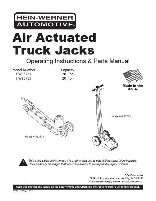
Operating Instructions & Parts ManualSFA Companies10939 N. Pomona Ave. Kansas City, MO 64153******************************************Model Number HW93731 HW93733Air Actuated Truck JacksCapacity 20 Ton 20 TonThis is the safety alert symbol. It is used to alert you to potential personal injury hazards. Obey all safety messages that follow this symbol to avoid possible injury or death.Model HW93731Model HW93733Made in the U.S.A.SAFETY AND GENERAL INFORMATIONSave these instructions. For your safety, read, understand, and follow the information provided with and on this jack. The owner and operator shall have an understanding of this jack and safe operating procedures before attempting to use. The owner and operator shall be aware that use and repair of this product may require special skills and knowledge. Instructions and safety information shall be conveyed in the operator's native language before use of this jack is authorized. If any doubt exists as to the safe and proper use of this jack, remove from service immediately.Inspect before each use. Do not use if broken, bent, cracked, or damaged parts (including labels) are noted. Any jack that appears damaged in any way, operates abnormally or is missing parts, shall be removed from service immediately and the manufacturer notified. If you suspect that the jack was subjected to a shock load (a load dropped suddenly, unexpectedly upon it), immediately discontinue use until the jack has been checked by a Hein-Werner authorized service center (contact distributor or manufacturer for list of Authorized Service Centers). It is recommended that an annual inspection be done by qualified personnel. Replace worn or damaged parts and assemblies with Hein-Werner authorized replacement parts only (see Replacement Parts, pages 6 thru 11).PRODUCT DESCRIPTIONHein-Werner Air Actuated Hydraulic Truck Jacks are designed to lift, but not support, rated capacity loads. They are designed to be used vertically. Immediately after lifting, loads must be supported by appropriate mechanical means (as opposed to hydraulic means), such as a pair of appropriately rated jack stands.WARNING: NEVER use a hydraulic jack as a stand-alone device. After lifting, immediately support the vehiclewith a pair of appropriately rated stands.! CAUTION! WARNINGNOTICESIGNAL WORDSIndicates situation which, if not avoided, will result in death or serious injury Indicates situation which, if not avoided, could result in death or serious injury Indicates situation which, if not avoided, could result in minor or moderate injuryIndicates situation which, if not avoided, could result in damage to propertySPECIFICATIONSFigure 1 - Model HW93731 NomenclatureModel HW93731Rated Load Capacity 20 tons (40,000 lbs)Low Pick Up Height 9-1/2"High Lifting Point 17-1/2"Power Raise 5-1/2"Screw Extension 2-1/2"Base Size 8" x 5-1/2"Ram Diameter 2-3/16"Handle Length 50"Wheel Diameter 6"Max. Air Pressure Supply 150 psiRequired Air Pressure For Lifting Loads140 psi for 40,000 lb.125 psi for 35,400 lb.100 psi for 27,900 lb.75 psi for 19,700 lb.Model HW93733Rated Load Capacity20 tons (40,000lbs)Low Height9"High Height With Extension 19-3/4"Screw Extension 4 3/4"Lift Cap Diameter 2"Wheel Diameter 8"Chassis Overall Length 20"Width at Wheels 13-1/4"Handle Length 45"Base Size8" x 17"Max. Air Pressure Supply 150 psi Typical Operating Pressure 125 - 150 psi Typical Lift Time - Full Raise (20 ton, 150 psi)2 min. 15 secFigure 2 - Model HW93733 NomenclatureHydraulic UnitValve KnobSaddleLift Control ValvePREPARATION1. Verify that the product and the application are compatible, if in doubt contact Hein-Werner Technical Service (816) 891-6390.2. Read the operator's manual completely and familiarize yourself thoroughly with the product and its components, and recognize the potential hazards associated with its use before using this product.3. To familiarize yourself with the basic operation of the jack, locate and turn the release valve knob:a. Clockwise until firm resistance is felt to further turning.This is the ‘CLOSED’ release valve position used to raise the load.b. Counter-clockwise, but no more than 1/2 full turn fromthe closed position. This is the ‘OPEN’ release valve position used to lower the load. The more you turn the release valve knob counter-clockwise, the faster the load descends.4. Locate and remove the oil filler screw (ref. part #13 for Model HW93731, part #24 for Model HW93733, in replacement parts section) with ram fully retracted. This will help release any pressurized air which may be trapped within the reservoir. Check oil level. Proper oil level should be just below the rim of oil filler hole.Model HW93731 A ir Bleeding - A rrow indicates approximate Air Vent Screw location.5. Reinstall oil filler screw.6. For Model HW93733, remove the shipping plug and install with air line elbow to reservoir (ref. part #47 in replacement parts section).7. Remove the plastic plug from air supply inlet and install a 1/4” PT air coupler (not provided). To ensure dependable, trouble free operation, an inline air dryer and oiler is recommended.NOTICE:Ensure that thread tape or compound is used when servicing connections.8. Pour a teaspoon of good quality air tool lubricant, such as #630-AAA Lubriplate, into the air supply inlet of the lift control valve. Connect to adequate air source and operate for 3 seconds to evenly distribute lubricant.9. Ensure that jack rolls freely. Raise and lower the unloaded saddle throughout the lifting range before putting into service to ensure the pump operates smoothly. Replace worn or damaged parts with Hein-Werner replacement parts only. Lubricate as instructed in Maintenance Section.OPERATIONLiftingNOTICE:Loosen the filler screw before use.1. Connect air source to the air supply inlet.2. Follow the vehicle manufacturer’s recommended guidelines for lifting. Engage the emergency brake and chock each unlifted wheel in both directions to prevent inadvertent vehicle movement.3. Locate and close the release valve by turning the release valve knob clockwise until firm resistance is felt.4. Refer to the vehicle manufacturer owner’s manual to locate approved lifting points on the vehicle. Center jack saddle under lift point.5. Verify lift point, squeeze the lift control valve until saddle contacts load. To lift, continue squeezing the lift control. Release the grip on the lift control valve when load reaches desired height.6. Immediately transfer the load to appropriately rated jack stands.WARNING: Overloading may cause hydraulicsystem failure.LoweringWARNING: Clear all tools and personnel beforelowering vehicle. Open the release valve slowly.Maintain control of speed at which the loaddecends at all times.1. Raise load high enough to clear the jack stands; then remove jack stands.2. Slowly turn release valve knob counter-clockwise, but no more than 1/2 turn. If the load fails to lower:a. Use another jack to raise the vehicle high enough toreinstall jack stands.b. Remove the malfunctioning jack and then jackstands.c. Using the non-malfunctioning jack, lower the load.3. After removing jack from under load, push saddle down to reduce ram exposure to rust and contamination.MAINTENANCENOTICE: Use only quality hydraulic jack fluid. Avoid mixing different types of fluid and never use brake fluid, turbine oil, transmission fluid, motor oil or glycerin. Improper fluid can cause failure of the jack and the potential for sudden and immediate loss of load. Hein-Werner hydraulic jack oil HW93291 or equivalent is recommended.Adding Fluid1. With saddle fully lowered, set jack in its upright, level position. Locate and remove oil filler screw. It may be necessary to remove cover plate on model HW93733.2. Fill with hydraulic fluid until just below the rim of the oil filler hole. Reinstall oil filler screw.Changing FluidNOTICE: For best performance and longest life, completely replace fluid supply annually.1. With saddle fully lowered, and pump piston fully depressed, remove oil filler screw. It may be necessary to remove cover plate on model HW93733.2. Lay the jack on its side and drain the fluid into a suitable container.NOTICE: Dispose of hydraulic fluid in accordance with local environmental regulations.3. Set jack in its level, upright position and fill with fluiduntil just below the rim of the oil filler hole. Reinstall the oil filler screw.Lubrication1. A periodic coating of light lubricating oil to pivot points,axles and hinges will help to prevent rust and assure that wheels move freely and the pump functions smoothly.2. When used on a daily basis, air pump should beinternally lubricated before each use. Use only good quality air tool lubricant such as #630 - AAA Lubriplate.If no inline oiler is used, pour a teaspoon of air tool oil into the inlet of the air control valve. Simply operate the jack using the air feature in order to fully distribute the oil.CleaningPeriodically inspect the ram for signs of rust or corrosion. Clean as needed and wipe with an oily cloth.NOTICE: Never use sandpaper or abrasive material on these surfaces.StorageWhen not in use, store the jack with ram fully retracted. REPLACEMENT PARTS(refer to page 6 thru 11)Not all components of the jack are replacement items, but are illustrated as a convenient reference of location and position in the assembly sequence. When ordering parts, give model number, part number and part description. Call or write for current pricing: Hein-Werner Customer Support, 10939 N. Pomona Ave., Kansas City, MO 64153. Phone: (816) 891-6390; E-mail: customerservices@ TROUBLESHOOTINGSymptom Possible Causes Corrective ActionJack will not lift load • Release valve not tightly closed• Overload condition• Air supply inadequate• Ensure release valve tightly closed•Remedy overload condition• Ensure adequate air supplyJack will lift, but not maintain pressure •Release valve not tightly closed•Overload condition•Hydraulic unit malfunction•Ensure release valve tightly closed•Remedy overload condition•Contact Tech. ServiceJack will not lower after unloading• Reservoir overfilled• Linkage binding • Ensure load is removed, then drain fluid to proper level• Clean and lubricate moving partsPoor lift performance • Fluid level low•Air trapped in system• Ensure proper fluid level•With saddle fully lowered, removeoil filler plug to let pressurized airescape, then reinstall oil filler plugJack will not lift to full extension • Fluid level low•Ensure proper fluid levelFigure 3 - Parts Illustration for Model HW93731 - Main13962632616028192743348395, 14593149544115642917492097832125616571826582431335237434447343930252242231135Apply Never-Seez (or equivalent) to threads and face at both ends of Ram Cylinder (ref part #44)before assembling. Assemble to Base (part #59) and tighten to crush fit.Lubricate O-rings (part #37 & 47), Tank Nut (part #43), and upper & lower of Oil Tank (part #58)with lubriplate (or comparable lubricant) before assembling. Tighten to a crush fit.A B AA B B B BAir-Hydraulic Pump Assembly(refer to Fig. 5)Ram Assembly(refer to Fig. 4)Figure 4 - Parts Illustration for Model HW93731 -Ram Assembly55531746505145386402110Figure 5 - Parts Illustration for Model HW93731 -Air Hydraulic Pump AssemblyFigure 6 - Parts Illustration for Model HW93731 -Pump Piston Assembly779579727794938865879882708684858092691018366698996}76Piston Assembly(refer to Fig. 6)7381786775991006871907491}97Apply Loctite #242 (color blue) to threads before assemblingThread into Piston todimensions shown0.060"0.080"Replacement Parts List For Model HW93731 - ref pages 6 & 7 for parts drawing(*) indicates items included in Repair Kit 240579(#) indicates items included in Repair Kit 240564Item Part No.Description Qty148230Washer 2250062Bolt 23*200003Gasket24201733ExpansionPlug15201787Lockwasher 16*203199Ball 17*203202Ball 38204446Cotter Pin 29210311Pipe Plug 110210411Washer 111211737Lockwasher112212227PoppetReleaseValve113212540Filler Screw 114212566Bolt 115213728Spacer 116*214555O-ring 117216647Spring 218217649Roll Pin 219217898Roll Pin 120222533Screen 121223166Screen 122223172Hose Clip 123351000Air Valve124212562Air VentScrew125224081Screw 126224164Adapter 127224165Rod 128224166Hand Knob 129224180Spacer 130224182Air Hose 131224472Spacer 132224475Wheel 233224521Handle134224640BalanceStrap135224641Handle Grip 136224644Bolt 337*224648O-ring 138225483Pin 139226019Hex Locknut 540226331Spring1Item Part No.Description Qty41226401Spring 242226483Pipe nipple 143227136Tank Nut144227533RamCylinder145228090Cross pin 146228091Cross pin 147228099O-ring148228929Air-hydraulicPump Assy.149229131Pipe Plug 250230125Heel Plate151230126U-cupPacking 152230134RamAssembly153245958Ram 154231102Axle155232618ExtensionScrew Assy.156*233917PlasticSpring 157233922ReleaseStem158234933Oil tank 159234935Base 160234990Strap261234999SupportBracket162236717Screw 163236718Nut 164242876Bushing 165203202Ball 166*#219861O-ring167*#221013U-cupPacking168221377Roll Pin169221820RetainingRing270222202Elbow 171*#222288O-ring172223173ReturnSpring173223183Plug1Item Part No.Description Qty 74223184Spring 175#223187Valve &Plunger 176223194Spring &Rubber Cushing177223203Trip Washer 278223678PumpPacking & Piston179223680Screen 180224034Air Cylinder 181224038Pump Rod 182224156Spring 183224469Washer 184225371Grommet 185225384Trip Spring 186226153Spring 187226373AdjustingScrew188N/A End Block 189226451Set Screw 290228235Cotter Pin 191228813Washer 192228814Gland Unit 193*#228815U-cupPacking194228816Washer 195228930PistonAssembly 196228933PumpCylinder197231347Piston & RollPin Assembly198N/A Cylinder Cap 199236684Piston 1100236685Sealing Ring 1101242877Bushing 1(*)240579Repair Kit -(#)240564Air Hyd. Pump Repair Kit-TWO YEARS LIMITED WARRANTYFor a period of two (2) years from date of purchase, SFA Companies will repair or replace, at its option, without charge, any of its products which fails due to a defect in material or workmanship under normal usage. This limited warranty is a consumer's exclusive remedy.Performance of any obligation under this warranty may be obtained by returning the warranted product, freight prepaid, to SFA Companies Warranty Service Department, 10939 N. Pomona Ave., Kansas City, MO 64153.Except where such limitations and exclusions are specifically prohibited by applicable law:(1) THE CONSUMER'S SOLE AND EXCLUSIVE REMEDY SHALL BE THE REPAIR OR REPLACEMENT OF DEFECTIVEPRODUCTS AS DESCRIBED ABOVE(2)SFA COMPANIES SHALL NOT BE LIABLE FOR ANY CONSEQUENTIAL OR INCIDENTAL DAMAGE OR LOSSWHATSOEVER.(3) ANY IMPLIED WARRANTIES, INCLUDING WITHOUT LIMITATION THE IMPLIED WARRANTIES OFMERCHANTABILITY AND FITNESS FOR A PARTICULAR PURPOSE, SHALL BE LIMITED TO TWO YEARS, OTHERWISE THE REPAIR, REPLACEMENT OR REFUND AS PROVIDED UNDER THIS EXPRESS LIMITED WARRANTY IS THE EXCLUSIVE REMEDY OF THE CONSUMER, AND IS PROVIDED IN LIEU OF ALL OTHER WARRANTIES, EXPRESS OR IMPLIED.(4) ANY MODIFICATION, ALTERATION, ABUSE, UNAUTHORIZED SERVICE OR ORNAMENTAL DESIGN VOIDSTHIS WARRANTY AND IS NOT COVERED BY THIS WARRANTY.Some states do not allow limitations on how long an implied warranty lasts, so the above limitation may not apply to you. Some states do not allow the exclusion or limitation of incidental or consequential damages, so the above limitation or exclusion may not apply to you. This warranty gives you specific legal rights, and you may also have other rights which vary from state to state.SFA Companies10939 N. Pomona Ave. Kansas City, MO 64153816-891-6390******************************************。
汽车英语缩写大全汽车英语缩写大全————————————————————————————————作者:————————————————————————————————日期:汽车英语缩写大全进口汽车维修技术缩略语词典??*C DegreesCelsius摄氏度?*F ?Deg rees Fahrenheit华氏度?*D* Drive 驱动,驾驶,行驶,行车?*N* Neutral Position 空档?*P*?*PARK*Position P档,停车档*P**PARK*Position P(驻车)档位置O2 ?Oxygen 氧气2WD ?Two-WheelDrive两轮驱动4WD Four-Wheel Drive四轮驱动4WS?Four-Wheel Steering四轮转向A ?A A-post, A-pillar A柱?A?Amperes 安培, 电流A?*Amper*Ammeter *Advance*安培*电流表*提前A.I.R. Air Injection Reactor 空气喷射反作用器A.M.Above-Mentioned上述的A/C AirConditioning空调?A/CA/C Amplifie空调放大器A/CCLTCH. A/C Clutch空调离合器A/CL Air Cleaner 空气滤清器?A/CL-BM AirCleaner BimetalSensor空气滤清器双金属传感器?A/CL-CWMAir Cleaner ColdWeather Modulator 空气滤清器低温调节器A/CL-DVAir Cleaner Duct Valve Vacuum Motor 空气滤清器导管阀真空马达A/CL-TSOV Air Cleaner TemperatureSensor Ove rride Valve ?空气滤清器温度传感器超压阀?A/CL-VCDAir CleanerVacuumControl Delay 空气滤清器真空延迟控制?A/CL-VCV Air CleanerVacuum ControlValve空气滤清器真空控制阀A/CL-VMAir Cleaner Vacuum Motor空气滤清器真空马达A/F Air-Fuel Ratio空燃比A/T Automatic Transaxle Or Transmission 自动变速箱?AA Automobile Association (UK)英国汽车协会?AA AAmericanAutomobile Association美国汽车协会AACAuxiliary AirControl辅助空气控制?AACAutomatic Amplitude Co ntrol自动振幅控制AACV Auxiliary Air Control Valve辅助空气控制阀?AADAuxiliary AirControl Device 辅助空气装置AAEAmericaAssociation of Engineers 美国工程师协会AAMVMAmericanAssociation of Motor Vehicle Manufacturers ??美国汽车制造者协会?AAP AuxiliaryAccelerator Pump辅助加速器泵?AAP Auxiliary Accelerating Pum p辅助加速泵AAPAmbient AbsolutePressure外界绝对压力?AAS Aspirator Air System吸气(真空)控制系统AAS Auto Adjust Suspension 自动调节悬挂?AAS Air Adjust Screw空气调整螺丝AAS American Astronautical Society 美国宇宙航行学会AAS Air Adjust Screw空气调节螺钉?AASHTO AmericanAssociation of S tate Highways and Transportation Off icials??美国各州公路及运输公务员协会?AAVAnti Afterburn V alve 防止后燃阀?AB AirBleed空气泄放ABA Air Bleed Actuator空气排放执行器(电磁阀)ABCV Air Bleed ControlValve空气泄放控制阀ABDC After Bottom DeadCenter在下止点后?ABGAlcohol BlendedGasoline掺酒精的汽油?ABNAirborne Noise 空气传播的噪音ABP Air BrakeProportioing(valves)空气制动比例分配( 阀)ABRS AirBag Restraint System 安全气囊?ABSAltitude Barometric Switch 高度(海拔)气压开关?ABS Anti-Lock Brake System防锁刹车系统,防抱刹车系统,反锁定刹车系统ABSAmerican Bureau ofStandards 美国标准局Abs Absolute绝对的ABSVisc Absolute Viscosity绝对粘度?ABSV Air Bypass S olenoid Valve空气旁通电磁阀ABV*AntiBackfire Valve *Air Bypass Valve*防止逆火阀*空气旁通阀?ABVAir Bypass Valve 空气旁通阀ABV Anti-BackfireValve防回火阀AC Air Condition 空调?AC Alternating Current Gener ator交流发电机?AC*Alternating Current *AfterContro *交流电*后段调整式?A CACAuxiliary Fan Relay空调辅助风扇继电器?AC AC Compressor Safety Switch空调压缩机安全开关?AC ACCondenser BlowerMotorRelay空调冷凝器鼓风马达继电器?AC AC Control Unit 空调电脑盒AC AC Diode空调二极管AC ACEvaporator Motor Relay空调蒸发马达继电器?ACAC Evaporat or Pump LineFuse空调蒸发泵保险丝AC AC HighPressure SafetySwitch空调高压安全开关AC ACIdle Boost Valve空调怠速加压阀?AC Alternating Current 交流电AC AnteChristum 公元前?AC Accumulator 蓄电池,储压器AC Acid酸ACAnalogue Computer模拟计算机?ACAutomaticControl 自动控制AC Air-Cooled 空冷AC ArmoredCar装甲汽车AC Adaptive Control自适应调节AC Aerodynamic Center空气动力中心ACAirCooling 风冷,空气冷却,气冷?AC Air Cycle 空气循环?AC Automatic Clutch自动离合器ACCA/CClutch Compressor 空调压缩机ACC Air Conditioning Clutch 空调离合器ACC Air ConditioningClutch Switch空调离合器开关ACC?Automatic Climate Control电脑恒温控制?ACC *Accessary*AltitudeCompensation Carb *附件*高度补偿化油器Accel?Accelerator油门,加速踏板,加速泵?ACCS?A/C ClutchCycling Switch 空调离合器循环开关ACCS?Air Conditoning CyclingSwitch空调循环开关?Accum Accumulat or蓄压器?ACCWM Air Cleaner Cold Weather Modulator 空气滤清器低温调节器?AccyAccessory 附件?ACD Auxiliary Control Device辅助控制装置?ACDAirConditioning Demand 空调作用指令ACD ?Air Conditioning Demand Switch 空调需求开关?A CDV Air Cleaner DiverterValve 空气滤清器分流阀?ACE ?Air Conditioning Equipment空气调节设备?ACE ?Automatic Check Equipment 自动检测设备?ACE ?Automatic Computing Equipment自动计算装置ACE Air Conditioning Equipment 空调设备?ACG ?A lternatingCurrentGenerator交流发电机?ACG Automatic Control Gear自动控制变速?ACID TEST CYC-LEAcceleration,Cruise, Idle,DecelerationTest Cycl e加速.稳速.怠速.减速试验循环ACIS ?Acoustic Control Iduction System 声控进气系统Ack Acknowledge承认ACKV?Air Check Valve 空气止回阀ACL?Air Clearner空气滤清器ACLAutomatic Chassis Lubrication自动底盘润滑系统ACM Advanced Composite Materials高级复合材料ACON ?AirConditioningOn 空调起动?ACP?AirConditioning Pressure空调压力ACP AuxiliaryControlPanel辅助操纵仪表板ACRS Air Cushion Restraint System气垫型保护装置ACS ?AirConditioning System 空调系统ACS-O?Access Opening检修孔?ACT AirCharge Tem perature进气温度ACT Air Charge TemperatureSensor进气温度传感器ACTE Automatic Checkout Test Equipment 自动检测装置ActuActuator执行器?Actv Active活动的?ACV Air Con trol Valve 空气控制阀?ACVAir Cut Valve 断气阀ACVArmored Command Vehicle装甲指挥车ACV Air ControlValve 二次空气喷射量控制阀?AD Anno Domini 公元?AD AerodynamicDecelerator气动减速器ADCAnalog-DigitalConverter模-数转换器?ADD Addition*添加*补充ADECS AutomotiveDiesel ElectronicControlSystem 汽车柴油机电子控制系统?ADFAerodynamic Drag Factor 空气阻力系数Adj Adjust or Adjustable调整或可调整ADL Automatic DoorLock自动门锁ADPAir-DrivenHydraulic Pump气动液压泵?ADS AdaptiveDampe rSystem 可变阻尼力避震系统ADV Wiper Pressure Control雨刷片压力控制装置Adv Advance提前的?AE AccelerationEnrichment 化油器加速时混合气浓度?AE Acoustic Emission 有害声响排放?AEA Automotive ElectricalAssociation (US) 美国汽车电气协会?AEC AutomotiveEmissionControl汽车排气控制AECD Auxiliary Emission Control Device 辅助排放控制装置AEI After End of Injection 喷射结束后AERAAutomotive Engine Rebuilders Association(US) 美国汽车引擎修护协会?AESC American Engineering Standards Committee美国工程标准委员会?AETS AutomaticEngine Test System发动机自动测试系统AF Air-Fuel Ratio混合气的空气燃油比?AF Auxiliary Fu el辅助燃料?AFC Airflow Controlled空气流量控制?AFC AirflowControlled FuelI njection 空气流量控制燃料喷射AFC AirFuel Control空气燃油混合比调节装置?AFCAutomatic Frequ ency Control 自动频率调节?AFC Airflow Control空气流量控制AFCOAutomatic Fuel Cutoff自动断油装置?AFCV Air Fuel RatioControl Valv e空燃比控制阀AFE Automobile Fuel Economy 汽车燃油经济性AFER Air-Fuel Equivalence Ratio燃油过量系数AFRAir-Fuel Ratio空气燃油混合比?AFS AirflowSensor空气流量传感器AFSAuxiliary Fuel Supply System 辅助供油系统?AG Air Guard空气护罩?AGO Automotive Gas Oil 汽车用油AGTAutomotiveGas Turbines 汽车用燃气轮机AGV AutomaticGuided Vehicle自动导向车辆AGVS Automatic Guided Vehicle System 车辆自动导向系统AHAmper Hour 安培小时?AHFSS AirConditionig /Heat er Function Select Switch空调/暖气功能选择开关?AI Air Injection 空气喷射?AICV Air Injection Check Valve空气喷射单向阀?AID AirInjection Dual双空气喷射?AIR AirInjectionReaction二次喷气装置?AIR Air Injector Reactor二次空气喷射器AIR BPV AirBypassValve 空气旁通阀?AIR COND RLY Air Conditioner Relay 空调继电器?AIR COND SIGAir Conditioner Singnal空调信号Air Sel Air Selector空气选择器AIR-CHVAIR Check Valve 空气单向阀?AIR-DVLV AIR DiverterValve空气分流阀AIR-IVV AIRIdleVacuum Valve进气怠速真空阀AIS AirInjection Single单空气喷射AIS AirInjection System二次喷气装置AISAutomatic Idle Speed自动怠速AIV AirInjection Valve 空气喷射阀?AIVVAIR Idle Vacuum Valve空气怠速真空阀?AKI Anti-KnockIndex抗爆震指数?AL Acceleratio nLevel 加速度级ALC Automatic LevelControl汽车后悬挂自动高度控制?ALCL Assembl yLine Communication Link诊断总线?ALDL AssemblyLine Diagnostic Link自我诊断接线总成ALDL Assembly Line Data Link 自我诊断线?Ali Alignment校正,定位AlmAlarm警报器?ALRAutomaticLocking Retractor 安全带自动锁定装置ALRAutomaticLength Adjusting and Locking Retra ctor?自动长度调节和锁紧式伸缩装置ALR Automatic Locking Retractor自动锁紧式伸缩装置?AltAlternatoror Altitude发电机,高度Alt Alternator交流发电机?ALU Arithmeticand Logical Unit算术及逻辑单位AM Amplitude Modulation 调幅Amb Ambient周围的?AMC American Motors Corporation 美国汽车公司?AMG V AirManagementValve空气控制阀Amm Ammeter电流表Amp Amplifier放大器?AmpAmpere安培AN Above-Named上述的?ANAnnual年度的AN Anode 阳极?ANCActiveNoise Control System活性噪音控制系统?ANLAutomatic Noise Limiter噪声自动限制器ANS Answer答案ANSI AmericanNational Standards Institute美国国家标准局Ant Antenna天线?ANTBV Anti-Backfire Valve防回火阀?Anti-Dsl Anti-Diesel防止後燃(熄火後)?AO Air Operated 气动的?AOC Air Oil Cooler机油空气冷却器?AOC Automatic OverloadControl自动超载控制?AODAutomatic Overdrive 自动超速?AOQ AverageOutgoing Quality平均产品质量AOT AutomaticOverdrive Transmission超速式自动变速器APAir Pump 气泵?APC AutomaticPhase Control自动相位调整?APC Automatic Power Control自动功率调整?AP CAutomatic ProgramControl 自动程序控制APC Armored PersonnelCarrier 装甲人员输送车?AP CAutomaticPerformance Control自动性能控制系统?APCV Air Pump Control Valve 空气泵控制阀?APDV Air Pump Diverter Valve空气泵分流阀API AmericanPetrol Institude美国石油协会AppApparatus仪表.器件. 设备?App Appendix附录App Approved by经...批准,批准人Approx Approximation近似.略计?Apr Apprentice学徒,徒工?APRA AutomotiveParts Rebuilders Associati on(US)美国汽车零件再制协会APREVLVAirPump Relief Valve空气泵减压阀APU Auxiliary Power Unit辅助动力设备?AQ Aqua(Wate r)*水*水柱?AR Air Regulator空气流量调节器?ARAxleRatio 驱动轴减速比?ARC Acceleration Signal加速信号ARQ AutomaticError Request Equipement自动误差校正装置ARV ArmoredRecovery Vehicle装甲抢救车AS AirflowSensor空气流量传感器AS American Standard美国标准AS AirSuction进气AS Automatic Synchronizer自动同步器?ASAAmericanSta ndard(s)Association美国标准化协会?ASA Acoustical Society of America美国声学学会ASCAutomatic StabilityControl 电脑控制稳定装置ASCD Auto Speed Control Device 自动速度调节装置ASCPS AirSwitch CanisterPurgeSolenoid 空气切换碳罐塞电磁阀ASCPTAir Switch Canister Purge Timer空气切换碳罐塞定时器ASD AutoShutDown 自动切断?ASDM Air BagSystemDiagnosticModule安全气囊系统诊断模块ASDV AirSwitching Diverter Valve 空气转换分流阀ASE Automatic StabilizationEquipment自动稳定装置ASIS Abort Sensing and Implementation System 紧急故障传感及处理系统ASIS American Societyfor IndustrialSecurity美国工业安全协会ASL Above Sea Level 海拔高度Asm Assembly 总成ASME AmericanSociety of Mechanical Engineers美国机械工程师协会?ASQC AmericanSocietyfor Quality Control 美国品管协会?ASRV Air Switching ReliefValve 空气转换减压阀?ASS Air SwitchingSolenoid 空气转换电磁阀ASS Air Suction System进气装置Ass Assembly总成,装配,机组?Ass Assistant辅助的,助手,帮手?As sAssociation 学会,协会.公司?AssyAssembly总成?ASTM America nSociety forTestingandMaterials美国材料试验协会ASVAir Switching Valve 空气转换阀?ASVAirSuction Valve 进气阀ASVAirSwitchingValve空气转换阀,空气开关阀?ASVSAir Switch ingVacuum Solenoid空气转换真空电磁阀?ATAc ceptanceTest验收试验AT Air Temperature空气温度?ATAmpere Turn安培匝数?ATAngle of Train方位角.方向角.传导方位ATAutomaticTransmission自动变速器?AT. Air Tight气密的,密封的At.Atmosphere大气.周围情况.Barometric 气压(计)BBattBattery电瓶电池BAV Bleed AirValve 泄气阀?BB Babbit Metal巴氏合金BBDC Before BottomDeadCenter在下止点前?BBL.Barrel 筒?BBSBuilding Block System积木式系统BC Befor Control前段控制?BCCBatteryChargerCont rol电瓶充电控制BCDD BoosterControlDecelerate Device 倍力控制减速装置BCM Body Control Module 车体控制模块(车体电脑)?BCV Boost ControlValve 真空控制阀溢油控制阀(三菱)减速节气阀(铃木)BCV Booster Control Valve倍力控制阀?BCV BoostControl Valve强制怠速时节气门开度控制阀?BCVBoost Contr ol Valve(铃木,三菱)强制怠速工况进气管真空控制阀?BDC BottomDead Center下止点.下死点BDVBreakdownVoltage击穿电压BE Banchelorof Engineering工学士?BEBaume 玻美度BEBooster Engine 助推发动机?BE Best Economy 最佳经济性BEI Breakerless ElectronicIgnition 无白金式电子点火?BESA British EngineeringStandardAssociation英国工程标准协会BFCBrake ForceCoefficient 制动力系数BFLI Brake Fluid LevelIndicator 制动液液面指示器BHPBrake Horsepower制动马力?BHS BimetalHeat Sensor 双金属热传感器?Bi Met BiMetallic Air T emperature Control Sensor双金属进气温控传感器BICERIBritish InternalCombustionEngineResearch Institute英国内燃机研究所BIT BestInjection Timing最佳喷油正时?BK Brake Swit ch 刹车开关?Bk Back 背部,後面,倒退,衬里Bk Rest Back Rest 椅背,後支架?BLKBlack黑色?BLRBlower 鼓风机BLRBeyond Local Repair本地不能修理?Blst Ballast稳压(电阻)BLU Blue 蓝色Blwr Blower鼓风机?BM BenchMark 基准点BM Breakdown Maintenance 故障维修?BM BreakeElec tromagnet制动电磁铁?BM BrakdownMaintenance 故障维修?BMAPBarometric and MainfoldAbsolute Pressure大气进气歧管绝对压力?BMEPBrake MeanEffective Pers sure 平均制动有效压力BNH Burnish抛光.精加工.烧蓝BOCBuick,Oldsmobile, Cadillac Group别克-奥兹莫比尔-凯迪莱克集团BOO BrakeOn-Off Switch制动开关BP Back Pressure 背压.反压BP Barometric Pressure气压?BPBoiling Point 沸点BPBestPower 最佳功率BPA BypassAir旁通空气BPCBack PressureControl背压控制BPO Bypass Orifice旁通口BPS Barometric Pressure Sensor 大气压力传感器BPTBackpressure Transducer 背压转换器BPVBy-PassValve 旁通阀Br Bromine溴?Br Brass 黄铜?Brkr Breaker 断电器BRN Brown 棕色?BS BarometricSwitch大气压力开关BSBimetalSensor 双金属传感器?BSBachelor of Science 理工学士BSBinary Scale二进位?BS Both Sides 两边.两侧?BS Briti sh Standards英国(工业)标准BSAUBritish StandardsAutomotive 英国汽车标准?BSC ENGBachlor of Science in Engineering工学士BSFC Brake Specific Fuel Consumption 制动油耗率, 制动单位油耗量?BSI British Standards Institute 英国标准局?BTC British Technical Council of the Motorand Petroleum Industries英国汽车及石油工业技术中心BTDCBeforeTopDeadCenter 在上止点前BTHEBrakeThermalEfficiency制动热效率BTRY Battery 蓄电池BTU British Thermal Units英国热量单位?BTV Below theThrottleValve 在节气门下方BUDC BoforeUpperDeadCentre 上死点前?BULKHD. Bulkhead隔壁?Buz B uzzer 蜂鸣器?BV Bowl VentPort浮桶室通风孔?BV Breakdowm Voltage击穿电压BV Balanced Voltage 平衡电压BVSV BimetallicVacuumSwitchingValve 双金属式真空转换阀?BVT BackPressure VariableTransducer负压可变传感器?BVV Bowl Vent Valve 浮筒室防溢油通气阀?BYP Bypass 旁路,支线?BYPA BypassAir(IdleSpeed Control) 旁通空气(怠速控制)CC Celcius 摄氏C C-Piller C柱CCall 呼叫C Candle烛光?CCapacitance 电容?C Car汽车CCarbon碳C Cathode 阴极?CCelsiusScale 摄氏温标?CCoulomb 库仑?C*Celcius 摄氏度?C&M Careand Maintenance 维修及保养C-4 Computer Controlled CatalyticConverter电脑控制触媒转换器C.CANI Charcoal Canister 碳罐C.E.Check Engine 引擎故障灯C.G. Center of Gravity 重心C/O Checkout 检查,调整,测试?C/O Choke Openner阻风门强制开启阀?C3IComputerControlledCoil Ignition 电脑控制线圈点火C4 Computer Controled Catalytic Converter 电脑控制触媒转换器?CA Calcium 钙?CA Compressed Air压缩空气?CA CrankAngle曲轴转角?CABRCabriolet 敞蓬车CAC ChargeAir Cooler 进气冷却器CACS Comprehensive Automobile Control System汽车综合控制系统CACV Combined AirControl Valve组合空气控制阀CADComputer-Aided Design 计算机辅助设计?CAEComputer Aided Enginering 电脑辅助工程?CAFECorporate AverageFuel Economy 美国汽车制造厂采用的平均油耗?CAL Calorie卡路里?CAL Calculated Average Life(汽车等的)平均计算寿命CALCaliber 口径CAL Calibrate 校定,校正?CAL Collision Avoidance Light 防撞灯CAL-PAC Calibration Package 校正用套装软体?CalibCalibration 校正,修正,定位?CalifCalifornia加州规格车?Calif California加州CALSEL Calibration Select校正选择?CAMCamber外倾角?CAM Camshaft 凸轮轴CAMComputerAided Manufacturing 电脑辅助制造?Can Canaba加拿大?Can Canister碳罐Can Prg Canister Purge碳罐塞Can.Prg Canister Purge 碳罐净化?Canc.Cancel 取消CanCV Canister ControlValve 碳罐控制阀?CANP Canister Purge solenoid碳罐清除电磁阀CANPCanisterPurge碳罐净化, 滤筒净化CAP Capacity *容量*能力CAP Cleaner AirPackage净化空气装置Cap Capacitor or Capacity 电容器或电容量?CARB California AirResource sBoard加州空气资源协会?Carb Carburetor化油器?CAS Caster 后倾角CAS ClearAirSystem净化空气系统?CAT Carburetor Air Temperature 化油器空气温度?CAT Catalogue目录CAT Catalyst 催化剂CATCategory种类.范畴?CATCarburator Air Temproture 化油器空气温度Cat Catalytic Converter 触媒转换器?CAV ConstructionAssistanceVehicle 建筑辅助运输车辆CAV Coasting AirVa lve 强制怠速空燃比控制阀?CBCircuit Breaker 电路断电器?CB ChokeBreaker 阻风门限制器CBContactBreaker 断电器CBE Cab Behind Engine 驾驶舱在引擎后方式?CBVVCarburetorBowl Vent Valve 化油器浮子室通气阀CCCubic Centimeters立方厘米?CC Cruise Control 定速控制,巡行控制CC Catalytic Converter触媒转化器CC Converter Clutch 扭力转换器离合器?CCCComputer Command Control 电脑指令控制CCCS ComputerControlled Cooling System 电脑控制冷却系统?CCD Computer Control Dwell 电脑控制点火闭角?CCEGRCoolant Controlled Exhaust Gas?Recirculation冷却剂控制废气再循环CCEVS Coolant Control Engine Vacuum Switch冷却水温控制引擎真空开关?CCEVV Coolant Control EngineVacuum Valve 冷却水温控制引擎真空阀?CCIVCoolant Control Idle EnrichmentValve 却水温控制怠速增浓阀?CCM CentralControlModule 中央控制模块(中央电脑)?CCOCatalytic Converter forOxidation氧化触媒转换器CCOT Cycling Clutch Orifice Tube 循环离合器限流孔?CCOT Cy cling Clutch (Orifice) Turbo 循环离合器涡轮增压CCPControlled Canister Purge控制碳罐净化CCP Charcoal CanisterPurge活性碳罐净化CCRCatalytic ConverterReduction还原催化废气净化器?CCRMConstant Control Relay Module定控制继电器模组CCROCatalytic Converter for Reductionand Oxidation三元触媒转换器CCRO CatalyticConverter Rhodium氧化,还原催化废气净化器?CCS Control led Combustion System 燃烧控制系统CCU Cruise Control Unit定速控制电脑盒CCWCounterclockwise 逆时针方向?CDComputer AidedDesign电脑辅助设计CD Candera 烛光?CDCapacity Discharge (electronic ignition)电容放电式电子点火?CDCompact Disc光盘?CD CapacitorDischarge(ignition)电容器放电(点火_)?CD Cofficientof Drag 空气阻力系数CD-REGVLVCrankcase DepressionRegulator Valve 曲轴箱真空调节器阀?CD-ROM CompactDisc ReadOnly Memory CD只读存储器CDI Capacitive Discharge Ignition电容放电式点系统?CDI Controlled Direc tInjection(system) 可控直喷系统CDY Chassis Dynamometer底盘测功计?CEAB Cold Eng ine Air Bleed 冷引擎空气排放CEC Computerized EmissionControl 电脑废气控制?CEC Combined Emission control(Valve)组合废气控制阀?CEC C omputerized Engine Control 电脑引擎控制CEC CoordinatingEuropean Council (standards)欧洲标准协会CELO ColdEngineLock-Out 冷机锁定CEMComposite Electro-Chemical Material复合电化学材料CENT Center中心CES Clutch EngagedSwitch 离合器啮合开关?CES Coast ingEnricherSystem 减速浓化系统?CESSCold Engine Sensor Switch 冷引擎传感器开关?CF C enter of Floatation浮心CFCentrifugal Force离心力?CF Conversion Factor 转换系数CFCutting Fluid切削液?CF Confer比较.对照?CF Cubic Feet立方英尺?CFCounter Fire 逆火?CFI Central FuelInjection 中央喷射系统?CFI CrossFi re Injection 多缸同时点火喷油?CFICentrolFuelInjection 节气门上方燃油喷射系统?CFI Continuous(throttle body)Fuel Injection 连续燃油喷射系统?CFRP Carbon Fiber Reinforced Plastics 碳纤维强化塑料CFSCoastingFuel Cut System 强制怠速工况燃油切断系统CH.O ChokeOpenner自动阻风门CHACharge 充电?CHBChoke Braker 阻风门开度限制器?CH G.Charge 进气或充电?CHK Check 核对,检查?Chk.Eng. Chec kEigine 检查引擎(灯)CHNGChange 交换CHO Choke Opener 阻风门开启器?CHRG Charging 进气,充电?CHT Cylinder HeadTemperature汽缸盖温度CHU CentigradeHeat Unit 热量单位?Ch Vlv CheckValve单向阀?CI Cubi cInches立方英寸CICompression Ignition压缩式点火CICompression Ignition Engine 压缩点火引擎CI CubicInches 立方英寸CI Cast Iron 铸铁CI Compression Ignition压燃?CIDCubic Inch Displacement 立方英寸排气量CID CylinderIdentification Sensor 气缸识别传感器?CID Cylinder Identification 汽缸识别?Cig Cigarette 香烟?Cig Ltr Cigarette Lighter点烟器Circ Circuit电路?Circ Brkr Circuit Breaker 电路断电器CIS Continuous Injection System 连续喷射系统CIS-E Continuous Injection System Electronic 电子控制连续喷射CK-VLV Check Valve 止回阀,单向阀CKD Completely Knocked Down完全拆散的,全解体的CKDL-VLV CheckDelayValve单向延迟阀?CKP Cran kshaft Position 曲轴位置?CKPS Crankshaft Position Se nsor曲轴位置传感器?Ckt. Circuit 电路,回路CLClosed Loop 闭环,闭路?CLCentral Line 中心线?CL CarLoad车辆载荷CLClass 等级. 种类CL Clearance 间隙CL CraneLoad 吊车起重量CL Chlorine 氯CLA Chemilumineceut Analyzer 光化学分析仪?CLC ConverterLocking Clutc h转换器锁定离合器CLCC Closed LoopCarburetor Control 闭环式化油器控制?Clch Clutch离合器CLD, CLA Chemiluminecent Detector(Analyzer)光化学分析仪?CLEC Closed Loop Emission Control 闭路废气控制CLKClock 时钟CLRC Clearance 间隙,空隙, 游隙Clmn. Coloumn 柱Clmt.Climate气候CLR Clear清除?CLR Current-Limiting Resistor限流电阻器CLS Closed Loop反馈控制?Clstr.Cluster 群,组CLTBI Closed Loop Throttle Body Injection 闭路回馈式单点喷射?CMCentimeter 厘米CMCenter of Mass 质量中心?CM Control Motor 控制马达CMET Coated Metal镀层金属CMH ColdMixtureHeater 冷车混合汽加热器?CMO Conventi onal Mineral Oil 常规矿物润滑油?CMPCamshaft Position 凸轮轴位置?CMPS Camshaft Positi on Sensor凸轮轴位置传感器Cmpnstr. Compensator 补偿器?Cmptr.Computer电脑CMVSS Canadian Motor Vehicle Safety Standard加拿大车辆安全标准CN ChangeNotice更改通知?CNCLD Concealed 隐藏式?CNG Compressed Natural Gas Automobile 天然气燃料汽车CNGCompressedNatural Gas 压缩天然气?CNT Constant 常数,恒量.恒定的?Cntr. Central orCenter 中心,中央?CNTRL Control 控制Cnvnc.Convenience便利,方便?CO Carbon Monoxide 一氧化碳CO ChokeOpener 阻风门助开器?Co-Ax. Co-Axial 同轴?CO2 Carbon Dioxide 二氧化碳?COC Conventional Oxidation Catalyst 普通氧化触媒COD Cash On Delivery 交货付款CODChemical Oxygen Demand化学耗氧量COE Cab Over Engine驾驶舱在引擎上?Colng.Coolng 冷却?Colnt. Coolant冷却液?Comb.Combination综合,组合?COMPCompressoror Compartme nt 压缩机或舱、室Comp.Compressor 压缩机Compens Compensation补偿Compt. Compartment 室?CON. ROD Connecting Rod连杆Cond.Condenser 电容器,冷凝器?Conn.Connector orConnection 连接器或接头CONT Continued连续?CONT. Control 控制?CONVConverter转换器CONV Convertible 敞蓬车Convs.Conversion 换算CORP Corporation 协会,社团,公司,企业Count. Counter 计数器(转数表)COV ControlValve 控制阀?CP Candera Power烛光CP Canister Purge 碳罐净化?CP Centre ofPressure压力中心?CP Crankshaf tPosition曲轴位置?CP CondensationProduct 冷凝物,浓缩物CP Carriage Paid 运费已付CP Chemical Pure 化学纯CP CircularPitch (齿轮)分度圆周节?CP ConstantPressure 等压,常压,恒压,稳定压力CPCV CanisterPurge Control Valve 碳罐净化控制阀?CPMCycles Per Minute 每分钟转数?CPPS Clutch Padel Position Switch离合器踏板位置开关CPRV Canister PurgeRegulator Valve 滤筒净化调节阀?CPS Canister PurgeSolenoid碳罐净化电磁阀?CPS Central Power Supply 集中电源供应CPSCrankPosition Sensor 曲轴位置传感器?CPS Cent ral Power Supply 中央电源?CPS Crankshaft Position Sensor 曲轴位置传感器?CPS Cycle Per Second 每秒周期数?CP SControl Pressure System 压力控制系统CPT Convertible PowerTrain 可变式传动系?CPU Cen tral ProcessingUnit 中央控制单元?CPUComputer 电脑CPV CanisterPurge Valve碳罐净化阀?CPV Constant Pre ssure Valve 定压阀CPVVV Choke PulldownVacuum Vent Valve阻风门真空强制通风阀?CRCrossroad 交叉路,十字路CRContraction Ratio压缩比CRECorrosionResistant防腐的,耐蚀的CRES CorrosionResistant Steel 耐蚀钢?CRK CrankingSignal 曲轴起动信号Crnr. Corner 角?CRNRNG Cornering 转向?CRO Cathode-RayOscilloscope 阴极射线示波器?CRS C hoke Return System 阻风门回位系统?CRS ChildRestraint System 儿童专用安全装置CRSCoasting Richer System 强迫怠速工况混合气加浓系统CRS Coolant Recovery System 密闭式冷却系统CRT Cathode Ray Tube阴极射线管CRTC Cathode Ray Tube Controller阴极射线管控制器CRVCoasting Richer Valve惯性(怠速)加浓(补偿)阀?CSA Cold Start Advance冷机起动提前装置CSC Coolant SpakConrol 冷却水点火控制?CSCSColdStartControl Solenoid冷车起动控制电磁阀?CSD Constant Speed Drive 等速传动?CSE GND Case Ground外壳接地CSPM Cold StartProgram Modifier 冷起动程序修正器?CSSCalibration Select Switch 校正选择开关CSSACold StartSpark Advance 冷车起动点火提前?CSSH ColdStart Spark Advance Hold(system) (福特)冷起动点火提前控制系统?CSU Crank Angle SelectingUnit曲轴转角自动调节装置?CT Cold Temperature冷车温度?CT Conventional Ther mactor 传统热反应器CT Cam-Train凸轮系?CT Closed Throttle关闭的节气门CTA Computer-Aided Test计算机辅助测试CTA Constant Temperatuer HotWire Anemometer常温热线风速计?CTAV Cold Temperature ActuatedVacuum 冷车温度动作真空?CTD Contrlolled Traction Differential 可控制(调整)牵引力差速器CTOCoolantTemperatureOverride 冷却水温过热控制CTPS Closed ThrottlePosition Switch 关闭节气门位置开关CTR Critical Temperature Resistance临界温度电阻?Ctrl. Control控制,控制器?Ctrlld Controlled 控制CTS Coolant Temperature Sensor冷却水温传感器?CTSCoolant TemperatureSwitch 水温开关?CTSWH Closed T hrottle Switch 节气门关闭开关?CTSY Courtesy门控灯?CTSY. C ourtesy 副, 反,对?CTTS CoolantTemperature Thermo Switch水温温控开关CTVS Choke Thermal Vacuum Switch 阻风门热控真空开关?CU Control unit电脑盒,控制器?Cu.In. CubicInches 立方英寸?CUBCubic立方?CURR Current电流CV ConstantVelocity 定速,等速CV CheckValve 单向阀?CVCheck Valve止回阀CV CoastingValve 滑行阀?CVConstant Velocity 定速, 等速CV ConstantVelocityJoint等速接头CV Control Valve 控制阀CV Calorific Valve 热值?CVCombat Vehicle 战斗车辆?C VCommercial Vehicle商用车辆,营运车辆CV Convertible 活动顶篷小客车CVConstant Volume Specific Heat 等容比热CVCritical Viscosity 临界粘度CVCConstant Vacuum Control 真空恒定控制CVC ConstantVoltageControl定电压控制?CVCCCompound Vertex ControlledCombussion 复合涡流控制式燃烧?CVCC ConstantVolume CombustionChamber等容燃烧室?CVRTContinuously Variable Ratio Transmission无级调速变速器?CVSConstant Volume Sampling定容量取样?CVS3PCold Vacuum Spark,3-Port冷车起动真空点火3孔式?CVSCC CoolantVa cuumSwitch Cold Closed 水温温控真空开关冷车关闭?CVSCO Coolant VacuumSwitch Cold Open水温温控真空开关冷车打开CVT Contiuously Variable Transmission无级变速器CVU Continuously-Variable Unit 无级变速器?CWClockwise顺时针方向CW Continuous Wave连续波,等幅波?CYCopy 副本,复制品?CYL Cylinder 气缸,油缸,圆柱?CYL Cylindrical圆柱形的D ?DDrive 驱动,行驶D Drive前进档?D *Diameter*Discharge*Drive*Dual *Double *直径*放电*驱动*双重*复式D&MDriving and Maintenance 驾驶与维修?D/O DeliveryOrder 提货单?Dam pDamper 阻尼器,缓冲器DAR Drive Axle Ratio驱动桥减速比?DASDistributor A dvanceSolenoid分电盘点火提前电磁阀?DASS Diesel Additive Supply System 柴油添加剂自动加添系统?DATA+DataPositive正线(自诊)DATA- Data Negative负线(自诊)DB Decibel 分贝DBCDual Bed Catalytic 双层触媒转换?DBP Drawbar Pull 拉杆拉力?DBW Drive-by-Wire索控式DC Direct Current直流电DC Digital Control 数位控制?DC DropCenter Rim深底钢圈?DC DeadCenter 死点DCELDirectCurrentLuminescence电流直接照明?DCHDual-Circuit Hydraulic System 双管路液压制动系统DCI Direct CylinderInjection直接喷入气缸(汽油喷射)?DCL Data Communications Link 数据交换连线DCLVDecelerationValve 减速阀DCM DirectCurrent Motor直流马达DCM/C-VLV DecelerationMixture Control Valve减速混合比控制阀?DCS Deceleration Control System 减速控制系统?DCTO Dual Coolant Temperature Override 双水温过热控制?DCV DecelerationControl Valve 减速控制阀?DCV Downdraft ConstantVacuum Carburettor 下吸式等真空化油器DD DualDistributors 双分电盘?DD Direct Drive 直接驱动?DDC Direct Digital Control 直接数字控制?Dual Diaphragm Distributor双膜片分油盘?DDV DistributorDecel Valve 分电盘减速阀De-Ice De-Icer 除冰装置?De-ice.De-Ice除冰DEC Digital Engine Control 数位引擎控制Decel Deceleration减速?DECS Daihatsu Economical Clean-Up System(大发)汽车经济式净化系统?DEEDi gital Engine Electronic发动机数字式电子控制单元?DEFDefrost er除雾器?DEFDieselExhaustFilter 柴油机的排气过滤器?Def Defrost er除霜器?DEF.DefoggerorDefroster除雾或除霜?DEFI Digital Electronic Fuel Injection数字式电子燃油喷射系统Defog Defogger除雾器?DegDegree度Del Delay 延迟DELO Diesel EngineLubricating Oil柴油机润滑油DERM Diagnostic Energy Reserve Module 自诊备用电源模块DesigDesignation 指明,标明,目标DET Detached 拆开的,分开的DET Detail零件.细目.详图.详细?DETDetection 检波.检测DET Dtector 检波器.探测仪Deton. Detonation 爆震,敲缸?DETRNT. Deterrent制止?DF Design Formula设计公式DF Direction Finding 测向.定向?DF Defogging去雾DFDrive Fit推入配合?DFF Direct Fuel Feed(injector)直接供油DFI Digital Fuel Injection 数字式汽油喷射?DFIP/D Diesel Distribution-Type Fuel Injection Pump柴油机分配式燃油喷射泵DftDefeat缺点,不良,损坏DG DoubleGlass双层玻璃?DG Double Groove双槽DI DecelerationIdle减低怠速?DI DirectInjection直接喷射DI Defense Industry 国防工业DI Deicing 防冻.去冰?DI Direction Indicator 方向指示器DI DieselIndex 柴油指数?DI.B Disk Brake 盘式制动器?DiagDiagnostic 诊断DIC Driver Information Center 行车电脑中心DIDVDual Ignition Delay Valve 双点火延迟阀?Diff Differential 差速器,差动的Dig. Digital 数字式?DIGRO DigitalReadout数字读出Dim Dimmer变光器?DINDeutsch Industrial德国工业标准规格?Dir Direction orDirectional 方向,定向,引导DIRSIDeposit Induced RunawaySurfaceIgnition表面点火方式DIS DirectIgnition System 直接点火系统?DIS Discharge放电DIS Distribution IgnitionSystem分电盘式点火系统DIS Doppler Inertial System多普勒惯性系统DISDigital Idling Stabilization数字式怠速稳定系统?DIS DistributorlessIgnition System无分电器点火系统?DIS Dual Induction System 双进气系统DispDisplay 显示DISTDistribution分配?DISTDistributor 分电器,分油盘?DITDirect Injection Turbocharged直喷式涡轮增压柴油机DITA Direct Injection Turbocharged Aftercooled 直喷式涡轮增压后冷柴油机?DIX. Deluxe豪华型?DIY Do-It-Yourself 自己动手维修车辆?DKBLU DarkBlue深蓝色DK GRN Dark Green深绿色DLDatumLevel 基准面DL Dead Load静载荷,静重,自重?DL Drawing List图纸清单?D LCData Link Connector自诊接头?DLI Distributorless Ignition无分电盘式电子点火DLL Design Limit Load 设计极限载荷?DLR Driving LampsR elay 行驶灯继电器DLSDigitalIdling Stabilization(unit) 数字式怠速稳定装置DLV DeflectionLimitin Volume 变形极限区?Dlx Deluxe 豪华型(高级的)Dly Delay延迟DM Diesel Moderate 柴油机用中级润滑油DMDehydrogenatedMixture 脱氢混合物?DM DesignManual设计手册DMDevelopment Milestone 发展里程碑DM Differential Motor差绕电动机?DM DriveMagnet 驱(启)动磁铁?DMEDigital MotorElectronics 数字电子引擎DMS Dual Manifold System 双歧管系统?DMS DistributorModulator System 分电盘调节系统Dn.Down 下,向下Dnshft Downshift 低档位,降档?DOCDirectOperating Cost 直接操作费用?DOD Departmentof Defense (美国)国防部?DOHC Double OverheadCams haft 双顶置凸轮轴?DOL DataOutput Line数据输出线DOT Department ofTransportation(US) 美国运输局?DP Dashpot 减速缓冲器DPDevelopment Prototype 开发原型.研制原型?DP DampProofing 防潮的,不透水的DP Data Processing数据处理?DP Dead Point死点.止点?DPDew Point露点?DP Diametral Pitch (齿轮)径节DP. CHAMBERDepression Chamber (三菱)化油器车滑轮增压控制装置?DPA DelayedPort Admission(system)延迟气口进气系统?DPADistributor PumpAssembly 分配式喷油泵总成DPBDual Power Brake 双管路助力制动DPCData ProcessingCenter数据处理中心DPDDual PointDistributor双白金分电盘DPDT Double-PoleDouble-Throw 双刀双掷(开关)?DPF DieselParticulate Filter 柴油机微粒过滤器?DPI Dual Plug Inhibit双塞抑制装置?DPSTDouble-Pole Single-Throw双刀单掷(开关)?DPTDepartment部.科.系.车间?DRDrive Ran ge 前进级DRDouble Reduction 两级减速?Dr Door门DR.B Drum Regulation Braker鼓式制动器DRB-II Diagnostic Readout Box诊断专用机?DRCV D istributorRetard Con trol Valve 分电盘延迟控制阀DRL Daytime Running Lmps 日间运转灯?DropDropping 电压降,降落,滴油DRS Distributor RetardSolenoid 分电盘迟滞电磁阀?DrvrDriver 驾驶员DS Distributor Spark 分电盘点火DS Detonation Sensor 爆震感知器DS Diesel Severe柴油机用高级润滑油DS Data Set数据组DSDesignSpecification 设计参数.设计说明书DS DrawingSummary 图纸一览表?DS-II Duraspark II 电子点火(第二代)DSC Doctor of Science理学博士?DSCC DigitalSpark ControlComputer 数字式点火控制计算机?Dsl Diesel柴油Dsl Diesel 柴油车DSM Design StandardsManual设计标准手册DstncDistance 距离DTDate日期?DTDescrepancy Tag误差标签DTDoubling Time 双倍时间?DT DoubleTire双轮胎?DTC Diagnostic TroubleCo de故障码?DTM Decel Throttle Modulator节流门减速调制器DTM Diagnostic TestMode 诊断测试模式?DTMS Diagnostic TestMode Selector 诊断测试模式选择器?DTP Department of Transport(UK)英国运输局?DTR DutyType Rat ing 负载型定额?DTS Detailed Test Specification详细试验说明书?DTVSDistributorThermal VacuumSwitch 分电盘温控真空开关?DV Decel Valve 减速阀DV Delay Valve 延迟阀DV Diverter Valve 分流阀?DVDevice装置.设备DV-TW DelayValve-Two Way二段式延迟阀?DVAC Distributor Vacuum Advanc eControl Valve分电盘真空提前控制阀DVAS Distributor Vacuum Advance Solenoid分电盘真空提前电磁阀?DVB Delay Vacuum Bypass System (福特)点火延迟。

CLEAN ROOMSAND REGULATED ENVIRONMENTS2For more than 45 years, Sauermann Group has designed, manufactured and sold products and services dedicated to the industrial and HVACR markets. The Group specifically focuses on the detection, measurement and control of indoor air quality (IAQ).Measurement instruments : Sauermann measurement instruments monitor a broad spectrum of indoor air quality parameters and serve a wide range of applications, from building ventilation (heating and air conditioning) systems, to cold-chain installations and combustion gas analysis. Backed by our testing laboratories and in-house research and development program, Sauermann instruments deliver the accu-racy and reliability that HVACR engineers need.Condensate management solutions : Safe and effective conden-sate management for air quality systems can be a challenge. Sauer-mann pumps are designed to look good, while our patented piston technology delivers whisper-quiet operation and unrivalled reliability.ABOUT USLOW SOUND LEVELLOW FAIL RATE HIGH PERFORMANCEHIGH ACCURACYUNMATCHED RELIABILITY MULTIPLE APPLICATIONSAccredited to NF EN ISO/IEC 17025:2017SCOPE N°2-6860AVAILABLE ON WWW.COFRAC.FRTEMPERATURE SCOPE N°2-6861AVAILABLE ON WWW.COFRAC.FRHUMIDITY3SUMMARYMultifunction . . . . . . . . . . . . . . . 08Pressure . . . . . . . . . . . . . . . . . . . 10Temperature and humidity . . . . . 12Air velocity and air flow . . . . . . 13Monitoring and regulation (06)All parameters . . . . . . . . . . . . . . . 16Data Logging (14)Multifunction . . . . . . . . . . . . . . . . 20Air velocity and air flow . . . . . . 22Commissioning,validation and maintenance ....18Our expertise . . . . . . . . . . . . . . . . 35Products and accessories . . . . . . 24Case study . . . . . . . . . . . . . . . . . . 32Clean rooms . . . . . . . . . . . . . . . . 04About us . . . . . . . . . . . . . . . . . . . 02For more information . . . . . . . . . 36Flawless air quality management,guaranteed . . . . . . . . . . . . . . . . 04A world of standardsand regulations . . . . . . . . . . . . 05DATA LOGGINGClean rooms environmentalmonitoring system . . . . . . . . . . . 32The perfect solution forpharmaceutical sector safety . . . . 34CLEAN ROOMSAt the cutting edge across all sectorsEffective ventilation system mana-gement is essential in any sector where airborne particles such as dust, bacteria, viruses, micro-par-ticles and aerosols can disrupt ope-rations .At Sauermann, we work hand in hand with our partners in industries ranging from advanced electronics and pharmaceuticals to aviation, hospitals and biotechno-logy .Spanning every aspect ofmetrologySauermann harnesses the fullbreadth of its metrology expertiseto help clean rooms adhere tostringent standards, from constantmonitoring to ad hoc tests andeverything in between: air flowbalancing, certified calibration,and testing and repairing of mea-surement instruments for pressure,humidity, temperature, air velocityand air flow, CO2concentrationand other parameters .The jewelin our crownControlled-environment buildingsdemand the very best monitoringand control instruments – certifiedand setting the gold standard forreliability .Sauermann has its ownmanufacturing facilities, in-houselaboratories accredited to SO17025:2017, and a team of on-site technicians with the requisiteexpertise, all backed by a 45-yeartrack record in metrology .That’swhy our customers rely on us tosupply flawless measurement ins-Flawless air quality management, guaranteedIn clean rooms, avoiding contamination depends on irreproachable indoor air quality mana-gement. That’s why, for 45 years, Sauermann has been putting the best of its R&D expertise to work for these critical environments, which are subject to particularly stringent standards. Our aim, as always, is to manufacture the best products and to deliver an impeccable service to industry professionals.tremely narrow margins, especial-ly when it comes to differential pressure .Each room has to be kept slightly above or below the pres-sure outside in order to prevent the risk of atmospheric contami-nation .Sauermann’s instruments are designed to provide the mea-surement accuracy and resolution that these demanding applications require .of each inlet of the ventilation sys-tem is divided by the total volumeof the room concerned .Mathematically is expressed bythis simple equation:ACH = Q/VACH = number of air changes perhourQ = air flowV = space volumeopened and to avoid unintendedcross-flows due to turbulence .Source: ISO 14644-4; Cleanrooms and associatedcontrolled environments Part 4: Design, constructionand start-upMONITORING AND REGULATIONIn clean rooms, air parameters need to be regulated and monitored around the clock .At Sauermann, we put every inch of our expertise to work to develop pre-mium measurement instruments that set the bar high for reliability, accuracy and durability .This type of application requires multifunction trans-mitters, or transmitters specially designed to measure a specific parameter .The constant monitoring system is linked to real-time regulation of the ventilation system via a network of instruments, which themselves are connected to a Supervisory Control and Data Acquisition (SCADA) system .This interconnected architecture, known as Building Automation, forms the core of Building Mana-tralised Technical Management systems (in industrial premises) – automation systems that also optimise the building’s energy use by analysing data collected by our measurement instruments .That’s why Sauermann’s transmitters are open by de-sign, meaning have standard outputs – both analogue and digital .And our transmitters offer the ultimate in flexibility when it comes to Building Management Sys-tem topology, structure and configuration .The aim is to monitor air quality parameters non-stop and around the clock, to achieve flawless indoor air quality management and to support preventive main-tenance of the ventilation system .For measuringtemperature and humidity.SolutionC 310with SVS and SHDI-150 probes 89Mobile application • Wireless pairing• Data visualisation • Free downloaduser-friendliness, they help professionals work more efficiently .What’smore, their modular design and range of attachable probes lets engineersbuild a custom measurement solution – all calibrated in Sauermann’sin-house laboratories, which are accredited by COFRAC to ISO 17025:2017 .Probes:Differential pressure: MPR 500Humidity: SHR 110Temperature: SPK 150Hot wire: SFC 900Vane: SH 10024PRODUCTITEMREF.MEASURED PARAMETERSDESCRIPTION++TransmittersOur most common articles for clean rooms and regulated environmentsPa: Differential pressure - °C/°F: Temperature - % RH: Relative humidity - m/s: Air velocity - m 3/h: Airflow - ppm: Gas concentration25TransmittersOur most common articles for clean rooms and regulated environmentsPRODUCTITEMREF.MEASURED PARAMETERSDESCRIPTIONP r e s s u r eT e m p e r a t u r e a n d h u m i d i t yA i r v e l o c i t y a n d fl o w r a t ePa: Differential pressure - °C/°F: Temperature - % RH: Relative humidity - m/s: Air velocity - m 3/h: Airflow - ppm: Gas concentration26ACCESSORIESITEMREFMEASURED PARAMETERSDESCRIPTIONAccessoriesPa: Differential pressure - °C/°F: Temperature - % RH: Relative humidity - m/s: Air velocity - m 3/h: Airflow - ppm: Gas concentration27ACCESSORIES ITEM REF MEASURED PARAMETERSDESCRIPTIONPa: Differential pressure - °C/°F: Temperature - % RH: Relative humidity - m/s: Air velocity - m 3/h: Airflow - ppm: Gas concentrationCustomized ProductsIf you cannot find the product (instrument, probe, accessory) that suites your specific needs in this list, we can also deliver a large range of products that are available with longer delivery lead times.28PRODUCTITEMREFMEASURED PARAMETERSDESCRIPTIONCustomized ProductsIf you cannot find the product (instrument, probe, accessory) that suites your specific needs in this list, we can also deliver a large range of products that are available with longer delivery lead times.Data loggersOur most common articles for clean rooms and regulated environmentsA l l p a r a m e t e r sPa: Differential pressure - °C/°F: Temperature - % RH: Relative humidity - m/s: Air velocity - m 3/h: Airflow - ppm: Gas concentration29PRODUCTITEMREFMEASURED PARAMETERSDESCRIPTIONPortable instrumentsOur most common articles for clean rooms and regulated environmentsM u l t i f u n c t i o nPa: Differential pressure - °C/°F: Temperature - % RH: Relative humidity - m/s: Air velocity - m 3/h: Airflow - ppm: Gas concentration30ACCESSORIESITEMREFMEASURED PARAMETERSDESCRIPTIONPa: Differential pressure - °C/°F: Temperature - % RH: Relative humidity - m/s: Air velocity - m 3/h: Airflow - ppm: Gas concentrationAccessories31PRODUCTITEMREFMEASURED PARAMETERSDESCRIPTIONACCESSORIES ITEM REF MEASURED PARAMETERSDESCRIPTIONAirflow metersOur most common articles for clean rooms and regulated environmentsPa: Differential pressure - °C/°F: Temperature - % RH: Relative humidity - m/s: Air velocity - m 3/h: Airflow - ppm: Gas concentrationA i r v e l o c i t y a n d a i r fl o w32Clean Room Environmental Monitoring SystemThe installation required continuous and instantaneous information about the maintenance of pressure differential between ISO graded spaces for its packaging production lines. Sauermann responded with the supply of wall mounted Sauer-mann CPE 310-S multifunction panel transmitters combined with a vendor agnostic software and elec-tronic control system. The software continuously polls the units to ex-tract and record differential pres-sure, temperature and humidity.Always connected monitoringThe transmitters conveniently fit into recesses embedded in support columns and walls with high visibility,providing smooth and easy to clean surfaces. Compliance is governed through the application of alarm thresholds set against data received from each Sauermann transmit-ter. On the Packing room floor the software enables the visua-lisation of operational compliance for pres-sure in real-time through a tricolour indicator system located in each ISO 5 space. Operatives in each space communicate with the sys-tem via wireless web enabled tablet computers. On event, operatives provide acknowledgements and other actions using touch screen responses which are time and date stamped and recorded.At its core is SQL Server and SQL Connect. System security operates within the M icrosoft SQL Server security mo-del. The system can be configured to support other critical plant such as generators, UPS systems and HVAC using a variety of industry standardprotocols.In 2021, Sauermann UK delivered comprehensive environmentalmonitoring for one of the world’s leading pharmaceuticalpackaging companiesbased in Yorkshire.33Large format screens in ISO 7 areas deliver acomprehensive view of the operating status of all monitored spaces.The system is customisable, very sca-lable and vendor agnostic the ideal engineering solution for Sauermann UK. The system features a powerful historian designed to satisfy industry regulators and Quality Assurance. Alarm events, change management and system activity information is stored on the system in encrypted log files. Qua-lity Assurance and Operations manage-ment have access to a graphing engine, system reports and an alarm manager, all of which are available on demand to provide event duration information and event history in pre-formatted pdf reports.Easy visualisations and alertsPerformance analysis for pressure deli-very can be derived from single or mul-tiple series graphs comprising groups of sensor values enabling instant ac-cess to correlations. This is particularly useful in the visualisation of pressure cascading as people and product pass through pressurised areas and deter-mining working comfort for operatives in PPE equipment. Graphical data can be shown in tabular form for export to spreadsheets for further analysis or useby HVAC contractors and maintenance personnel. The Clean room systems operate continuously.Sauermann casestudy cleanroom monitoring During out of hours periods such as week-ends and public holidays, the company has visibility of the EMS sys-tem remotely via web access, conditio-nally sent emails and SMS messaging. The SMS system is uniquely bi-directio-nal. This means that recipients of such messages can be automatically alerted to the most severe alarm conditions such as a power failure where they cantake ownership and suppress further alerts in providing a remedy.34The Perfect Solution forPharmaceutical Sector SafetyIt is therefore essential to monitor the processing, packaging and sto-rage areas based on strict regula-tions and standards.Various places throughout phar-maceutical facilities will require constant pressure and temperature monitoring. Peoples` health often depends on these drugs being pro-perly stored.This monitoring means tracking the pressure and/or temperature changes, which can significantly im-pact the products' quality and effec-tiveness.The Sauermann Group's Kimo Ins-truments in Italy recently provided Ibsa Farmaceutici in Lodi with 70 CP210 BNR and CP211 BNR for use in their facilities, including Laminar Air Flow (LAF) environments.These instruments measure air ve-locity, airflow and pressure and are ideal for use in industrial and phar-maceutical applications.In this case, our sensors are ensuring that syringes and phials in asepsis are being stored properly!The Sauermann Group is a name that is trusted in medtech and thepharmaceutical industry!Within thepharmaceutical sector, it is very important to maintain high quality levels for stored products.70 CP210 BNR and CP211 BNR for use in their facilities,including Laminar Air Flow (LAF) environments.Page 06 -1735Pressure Temperature Humidity Weight Radiometry Tachometry Air velocityAir flowGas analysis Light measurement Electrical current AcousticsOur measurement expertise covers a wide range of fields:07/2022 R C S (24) P ér iFor more information, visit:Case studies, useful information and practical advice。
航空发念头专业英语词汇年夜全,值得收藏!0129 航佳技术飞机维修砖家Part 1Para. 1gas turbine engine燃气涡轮发念头aircraft 飞机,遨游翱翔器(单复同形)power plant 发念头,动力装置appreciate 理解,意思到prior to 在…之前propulsion 推进reaction 反作用jet 喷气, 喷射, 喷气发念头designer 设计师initially 最初,开始时unsuitability 不适应性piston engine 活塞发念头airflow 空气流present 带来, 产生obstacle 障碍Para. 2patent 专利, 获得专利jet propulsionengine 喷气推进发念头athodyd 冲压式喷气发念头heat resistingmaterial 耐热资料develop 研究出,研制出in the secondplace 其次inefficient 效率底的ram jet, ramjet冲压式喷气发念头conception 构想, 设计,概念Para. 3grant 授予propulsive jet 推进喷射turbojet engine 涡轮喷气发念头turbojet turbopropellerengine涡轮螺桨发念头turbopropVickers Viscountaircraft 维克斯子爵式飞机be fitted with 配备term 术语, 称为, 叫做twinspool engine 双转子发念头triplespoolengine三转子发念头bypass engine 双涵道发念头ducted fan 涵道电扇发念头unducted fan (UDF)无涵道电扇发念头propfan 桨扇发念头inevitable 不成避免的, 必定的p.4propeller 螺旋桨basic principle 基来源根基理effect 产生propel 推进solely 单独, 只thrust 推力p.5popularly 普遍地, 一般地pulse jet 脉动式喷气发念头turbo/ram jet 涡轮冲压式喷气发念头turborocket 涡轮火箭p.6accelerate 加速acceleration 加速度apparatus 装置, 机器slipstream 滑流p.7momentum 动量issue 冒出to impart M to N 把M给与N revolve 旋转p.8whirl 旋转sprinkler 喷水器mechanism 机构by [in] virtue of 依靠hose 软管afford 提供carnival 狂欢节p.9definitely 确切地, 明确地assume 想象, 以为expel 排出, 驱逐propulsiveefficiency 推进效率Page 3p.10differ 不合convert 转换p.11thermodynamic 热动力的divergent 扩散diverge 扩散convergent 收敛converge收敛entry 进气段exit 排气管kinetic energy 动能air intake 空气进口diverging duct 扩散管道outlet duct 排气管missile 导弹target vehicle 靶机p.12 intermittentcombustion 间断式燃烧aerodynamic 空气动力的involve 具有robust 结实的, 坚固的inlet valve 进气阀inject 喷入eject 喷出depression 降压, 减压exhaust 排气cycle 循环helicopter rotorpropulsion直升飞机旋翼驱动器dispense with 省去, 无需resonate 共振resonating cycle 共振循环fuel consumption 燃油消耗equal 比得上performance 性能p.13decompose 分化p.14inherent 固有的draw 吸入p.15arrangement 结构simplicity 简单性subsequent 接下来的thermodynamic 热力的Page 7p.16disturbance 扰动bladetip 叶尖departure from 叛变p.17offset 抵消exceed 超出p.18Mach number 马赫数p.19variable intake 可变进口afterburning 加力燃烧variable nozzle 可调喷口conventional 惯例的afterburner 加力燃烧室inoperative 不工作的divert 使转向guide vane 导流叶片duct 管道,用管道输送sustained 继续的cruise 巡航mode 模式p.21multistageturbine 多级涡轮derive 获得,取得kerosene, kerosine煤油be in the orderof…达到…的量级spray 喷雾fuelrich mixture 富油混合物dilute 稀释surplus 剩余的p.22interceptor 截击机spacelauncher 航天发射器altitude 高度attitude 态度、姿态latitude 纬度longitude 经度accelerative 加速的duration 继续时间Part2Para.1working fluid 工作流体conversion 转换jet efflux 喷射气流Para.2fourstroke pistonengine 四冲程活塞发念头constant pressure 等压constant volume 等容induction 进气compression 压缩intermittent 间断的be involved in…与…有关charging 进气eliminate 消除idle stroke 空冲程Para.3peak 峰, 峰值fluctuate,fluctuating 摆荡, 起伏withstand,withstood 接受in excess of 超出employ 采取cylinder 汽缸high octane fuel 高辛烷值燃料low octane fuel 低辛烷值燃料fabricated 装配式的Para.4function 运行, 运转introduce,introducing 输入remainder 剩余部分discharge 排出Para.5,6turbine assembly 涡轮部件aircooled blade 气冷叶片consequently 随之而来的, 因此, 所以Para.7embody 体现be embodied in M 体现在M中be directlyproportional to…与…成正比be inversely proportional to…与…成正比Para.9trace 描绘show up 表示Para.10attain 达到, 实现conversely 相反地Para.11adiabatic 绝热的friction 摩擦conduction 传导turbulence 紊流Para.12propelling nozzle 推力喷管momentum 动量deceleration 减速Page 14Para.13effect 实现conversion 转换convert 转换sonic 音速的subsonic 亚音速的supersonic 超音速的encounter 遇到venturi 文氏管Para.14interference 干扰component failure 部件失效eddy 涡流turbulence 紊流Para.15frontal area 迎面面积straightthroughflow system 直流式系统reverse flowsystem 回流式系统subsequent 接下来的Para.17conventionally 惯例地percentage 部分,百分比duct 管道,用管道输送remainder 剩余物deliver 送,流to be conducive to…有利于…specific fuelconsumption 燃油消耗率Para.18design feature 设计特征bypass engine 双涵道发念头bypass ratio 涵道比twinspoolconfiguration 双转子结构propfan 桨扇发念头turbopropeller 涡轮螺桨发念头Para.19bypass airstream 外涵道气流overboard 向船外,排出ducted fan 涵道式电扇发念头aft fan 后电扇发念头Part 3Para.1centrifugal 离心的axial 轴流的couple 耦合,联接coupling 联轴器coupler联轴器shaft 轴Para.2centrifugal (flow)compressor 离心压气机impeller 叶轮diffuser 扩散器axial (flow)compressor 轴流压气机multistage unit 多级装置alternate 交替的rotor blade转子叶片stator vane 静子叶片diffuse 扩散boost 增压booster 增压器Para.3with regard to 关于robust 坚固,结实develop andmanufacture 设计与制造consume 消耗,使用attain 达到air flow 空气流量,空气流adoption 采取favour (Am. E favor) 喜爱,偏爱ruggedness坚固性rugged 坚固的outweigh 胜过,重于Fig. 31rotating guidevane 旋转导流叶片intake chute 进气斜道swirl vane 旋流叶片Para.5diffuser vane 扩散器叶片doubleentry impeller双面进气叶轮plenum chamber 稳流室Para.6induce 吸入radially 径向地intake duct 进气管initial swirl 预旋Para.7divergent nozzle 扩散排气管Para.8tip speed 叶尖速度Para.9maintain 坚持leakage 泄漏clearance 间隙Para.10construction 结构center around(about, at, in, on, round, upon)…以…为中心ball bearing 滚珠轴承roller bearing 滚柱轴承split 分隔detachment 拆开,别离Para.11forged 铸造的radially disposedvanes 径向排列的叶片in conjunctionwith… 和…共同swept back 后掠Para.12attach 联接tangential 相切的inner edge 内缘in line with… 与…一致buffeting impulse 扰流抖振脉冲Para. 13rotor assembly 转子部件airfoilsection 翼型截面mount 装置bearing 轴承incorporate 安有,装有in series 依次地design condition 设计状态incorporation 引入,采取variable statorvane 可调静子叶片succeeding stage下一级Para. 14gradual reduction 逐渐减小annulus 环型stator casing 静子机匣maintain 坚持density 密度convergence 收敛taper,tapering 带斜度,带锥度arrangement 结构Para. 16 multispoolcompressor 多转子压气机optimum 最佳(的),最优(的)flexibility 适应性,灵活性Para. 17handle 处理duct 管道,用管道输送exhaust system 排气系统propelling nozzle 推力喷管match 使匹配obsolete 已不必but 除…….之外Para. 18trend 趋势stage 阶段, 级undergo 接受split 分隔core 核心gas generator 燃气产生器optimumarrangement 最佳结构Para. 19induce 吸入,引入,引导sweep, swept 扫,猛推adjacent 相邻的translate 翻译,转换decelerate 减速serve 起……作用deflection 偏转straightener 整流器swirl 旋流diagrammatically 图示地accompany 陪伴progressive 不竭的,逐渐的Para. 20breakaway 别离stall 失速precede 在……前面Para. 21incidence 攻角tolerate 允许interstagebleed 级间放气intermediatestage 中间级Para. 22proportion 比例pl. 尺寸, 年夜小coaxial 同轴的inner radius 内半径supercharge 增压akin 相似的Para.23to center around(round, on, upon, about, at, in)…以…为中心alignment 对中, 同心cylindrical 圆筒形的bolted axial joint轴向螺栓联接bolted center linejoint 中心线螺栓联接Para.24secure 固定assemble 装配weld 焊接periphery 边沿drum 鼓筒Para.25circumferential 周向的fixing 装置, 固定maintainability 维护性blisk 整体叶盘Para.26gradient 梯度balance out 抵消twist 扭angle of incidence攻角boundary layer 附面层, 鸿沟层stagnant 滞止的compensate for 赔偿camber 弯度extremity 端部endbend 端弯Para.27retaining ring 坚持环in segments 成组的shroud 叶冠Para.28dissimilar 不相似的, 不合的workable 可用的, 可运转的implement 实现, 执行, 完成retain 坚持Para.29impose upon… 强加于…之上depart from 偏离intention 意图positive incidencestall 正攻角失速negative incidencestall 负攻角失速blading 叶栅sustain 接受得住surge 喘振instantaneous 即刻的expel 排出margin 欲度instability 不稳定性Para. 30provision 提供margin 欲度hydraulic 液压的pneumatic 气动的electronic 电子的Para. 31cost effective 本钱效益好的prevail 流行,胜利Para. 32rigid 刚性的clearance 间隙alloy 合金nickel based alloy镍基合金titanium 钛in preference to 优先于rigidity todensity ratio 刚度密度比Para. 33prime 主要的fatigue strength 疲劳强度notch 切口,开槽ingestion 吸气inferior 差的decline 下降rub 碰磨ignite 扑灭airworthiness 遨游翱翔性能hazard 危险Para. 34dominate 起支配作用Para. 35solid forging 实锻件chord 弦midspan 叶片中部snubber 减振器clapper 拍板fabricate 制造skin 蒙皮honeycomb 蜂窝Para. 36robust section 坚固截面ingestioncapability 吸气能力Part4Para.1fuel supply nozzle燃油喷嘴extensive 广泛的,年夜量的accomplish 完成Para.2range 规模CCentigrade orCelsiusturbine nozzle涡轮导向器Para.3consequent 随之产生的,结果的Para.4kerosene, cerosine煤油light, lit orlighted 扑灭blow, blew,blown 吹alight 燃烧的Para.5flame tube 火焰筒liner 衬筒meter, metering 调节配量Para.6snout 进气锥体downstream 下游,顺流swirl vane 旋流叶片perforated flare 带孔的喇叭管primary combustionzone 主燃区upstream上游,逆流promote 增进,引起recirculation 环流,回流Para.7secondary air hole二股气流孔toroidal vortex 喇叭口形涡流anchor, anchoring 锚,固定hasten 增进,加速droplet 小滴ignitiontemperature 燃点Para.8conical 锥形的intersect 相交turbulence 紊流break up, breakingup 割裂,破碎incoming 进来的Para.9nozzle guide vane 涡轮导向叶片amount to 占…比例, 达到progressively 逐渐地dilution zone 掺混区remainder 剩余物insulate M from N 使M与N隔离Para.10,11electric spark 电火花igniter plug 燃烧塞selfsustained 自持的Para.12airstream =airflowdistinct =different typeinjection 喷射,喷入ejection 喷射,喷出atomize 使雾化spray nozzle 喷嘴prevaporization 预蒸发Para.13vapor 蒸汽vaporize 蒸发vaporizer 蒸发器feed tube 供油管vaporizing tube 蒸发管atomizer flametube装有雾化喷嘴的火焰筒Para.14multiple(combustion) chamber 分担燃烧室tuboannular(combustion) chamber 环管燃烧室cannular(combustion) chamber 环管燃烧室annular(combustion) chamber 环形燃烧室Para.15F.g.46Para.16dispose 安插delivery 排气Para.17interconnect 互相连通propagate传播Para.18bridge a gapbetween填补空白,使连接起来evolutionary 成长,演变arrangement 结构overhaul 年夜修compactness 紧凑性Para.19contain 包含,装置be open to 与…相通Para.20elimination 消除propagation 传播Para.21virtually 实际上oxidize 氧化carbon monoxide 一氧化碳nontoxic 无毒的carbon dioxide 二氧化碳Para.22aerate, aerating 吹气,供气overrich pocket 过富区fuel vapour 燃油蒸汽carbon formation积碳形成Para.23incur 招致extinction 熄灭relight 重新扑灭perform,performing 完成,执行spray nozzleatomizer 喷嘴雾化器Para.25intensity 强度compact 紧凑的exceptionally 格外地,特别地Para.26calorific value 热值British thermalunit (BTU)英国热量单位=252卡expenditure 使用,消耗Para.27altitude cruise 高空巡航Para.29weak limit 贫油极限rich limit 富油极限extinguish 熄灭extinguisher 灭火器dive 爬升idle, idling 空载,慢速mixture strength 混合物浓度Para.30stability loop 稳定区Para.32emission 排放物pollutant污染物create 产生,形成legislatively 立法地hydrocarbon 碳氢化合物oxides of nitrogen氧化氮Para.34suppression 抑制desirable 合乎需要的conflict 冲突compromise 折中combustor 燃烧室substantially 实际上Para.35coating 涂层insulation 隔热,隔离Para.36corrosion 腐化creep failure 蠕变失效fatigue 疲劳Part5Para.1accessory,accessories 附件solely = onlyextract,extracting 提取to expose M to N 使M流露于NM is exposed to NPara.2torque 扭矩Para.3intermediate 中间的interpose 置于…之间to be derivedfrom… 从…获得, 取自freepower turbine自由动力涡轮to be independentof…不受…的限制Para.4mean 平均的deflection 偏转in proportion to 按比例sectionalthickness 截面厚度disproportionately不相称地Para.5broadly 主要地aerofoil shape 翼型形状impulse turbine 冲击式涡轮reaction turbine 反作用式涡轮incorporate 采取cartridge starter 弹药筒式起念头air starter 空气起念头Para.7to force one’s wayinto 有力地冲入spin 旋转whirl 旋转Para.8to be governed by 取决于, 由…决定substantially 实际上, 年夜体上excessive 过分的residual 剩余的,剩余detrimental =harmfulstrut 支柱, 支杆Para.9twist, twisted 带扭向的stagger angle 斜罩角Para.10mean section 中间截面Para.12selfaligningcoupling 自动调节联轴器Para.15machined forging 机加锻件flange 法兰,装置边bolt 螺栓,用螺栓联结perimeter 周边,圆周to have provisionfor…为…作好准备attachment 联接, 装置Para.16heat conduction 热传导Para.17degree of reaction反力度Para.18fix 确定, 决定,trailing edge 排气边so as to (do) 为了prevent M (from)+ingPara.19attach联接, 装置fixing 联接have a bearing on …对…有影响rim speed 轮缘速度de Laval bulb root圆头叶根supersede 取代, 取代firtree fixing 纵树榫头联接involve 需要, 要求serration 榫齿stiffen 加劲, 固牢Para.20contraction 收缩shroud 叶冠fit 配备, 装置segment 部分, 片peripheral 外围的, 周边的abradable lining 易磨涂层A.C.C. activeclearance control shroudless blade 无冠叶片Para.21revolve 旋转extract 提取conventional 惯例的Para.22impractical 不实际的dual alloy disc 双金属轮盘blisk 整体叶轮cast 铸造bond 粘接Para.23match 匹配nozzle guide vane 涡轮导向叶片back pressure 反压surge 喘振choke 壅塞,阻塞Para.24obstacle 障碍impart to…给与tensile stress 拉应力limiting factor 限制因素Para.25endure 接受nickel alloy 镍合金ceramic coating 陶瓷涂层enhance 增强Para.26resistance 抵当,耐fatigue cracking 疲劳破坏Para.27ferritic 铁素体terrific 可怕的,极妙的austenitic 奥氏体alloying element 合金元素extend 延长fatigue resistance抗疲劳性powder metallurgy 粉末冶金Para.28in connection with关于,与…有关glowing redhot 赤热发光ounce 盎施=28.35 gbending load 弯曲载荷thermal shock 热冲击corrosion 腐化oxidization 氧化Para.29foregoing 前面的, 上述的it follows that 因此, 可见permissible 允许的metallurgist 冶金学家Para.30creep 蠕变finite useful life有限使用寿命failure 失效Para.31forge 铸造forging 锻件cast 铸造creep property 蠕变性能fatigue property 疲劳性能Para.32reveal 揭示, 显示a myriad of 无数crystal 晶体equiaxed 等轴的service life 使用寿命directionalsolidification 定向凝固useful creep life 有效蠕变寿命single crystalblade 单晶叶片substantially 实质上, 显著地Para.33reinforced ceramic加固陶瓷Para.34balancing 平衡operation 工序in view of 考虑到Part 6Para.1aero 航空的pass 排送resultant thrust 合成推力,总推力create 引起,产生contribute 提供absorb 吸收exert an influenceon…对…产生影响jet pipe 尾喷管propelling nozzle 推力喷管outlet nozzle 出口喷管Para.2distortion 扭曲, 变形cracking 产生裂纹Para.3thrust reverser 推力反向装置noise suppressor 消音器entail 需要, 要求low bypass engine低涵道比发念头mixer unit 掺混装置encourage 增进Para.4exhaust cone 排气锥hold 坚持residual whirl 剩余旋流strut 支板straighten 整流Para.5in relation to…对…来说choked 壅塞, 阻塞upstream totalpressure 上游总压pressure thrust 压力推力momentum 动量Para.6wastage 损失, 消耗with advantage 有效地convergentdivergentnozzle 收扩喷管recover 重新获得Para.7flared 扩张的restriction 限制progressively 逐渐地longitudinal 纵向的Para.9fixed area nozzle 固定面积喷口variable areanozzle 可变面积喷口offset 抵消Para.13nickel 镍titanium 钛ventilate,ventilating 通风lag, lagging 用隔热资料呵护insulating blanket隔热层fibrous 纤维状的stainless steel 不锈钢dimple 使起波纹acousticallyabsorbent material 吸声资料Para.14 doublewallconstruction 双壁结构induce 引导ejector action 喷射器作用engine nacelle 发念头短舱Para.15streamline fairing流线型整流板vent hole 通气孔。
Non-Destructive Testing and Evaluation Non-Destructive Testing and Evaluation Non-destructive testing (NDT) is awide group of analysis techniques used in science and industry to evaluate the properties of a material, component, or system without causing damage. This is in contrast to destructive testing, which is used to determine the properties of a material by causing damage to the material. NDT is commonly used in the aerospace, automotive, and construction industries to ensure the safety and reliability of products and structures. In this essay, we will discuss the importance of non-destructive testing and evaluation and its various techniques. First and foremost, non-destructive testing and evaluation play a crucial role in ensuring the safety and reliability of products and structures. By using NDT techniques, manufacturers and engineers can detect flaws, defects, and discontinuities in materials and components without causing any damage. This allows for the early detection and prevention of potential failures, which is essential for maintaining the integrity of critical infrastructure and ensuring the safety of end users. There areseveral commonly used NDT techniques, each with its own advantages and limitations. One of the most widely used techniques is ultrasonic testing, which uses high-frequency sound waves to detect internal and surface defects in materials. Another common technique is radiographic testing, which uses X-rays or gamma rays tocreate images of the internal structure of a material. Other techniques include magnetic particle testing, liquid penetrant testing, and eddy current testing. Each of these techniques has its own unique applications and is used depending on the specific requirements of the material or component being evaluated. Inaddition to ensuring the safety and reliability of products and structures, non-destructive testing and evaluation also play a critical role in quality controland process optimization. By using NDT techniques, manufacturers can identify and eliminate defects in the early stages of production, leading to cost savings and improved efficiency. Furthermore, NDT can be used to monitor the performance and integrity of materials and components over time, allowing for predictive maintenance and extending the lifespan of critical infrastructure. Despite its numerous advantages, non-destructive testing and evaluation also have some limitations. One of the main challenges is the need for highly trained and skilledpersonnel to perform NDT techniques accurately and reliably. Additionally, some NDT techniques may be time-consuming and require specialized equipment, which can increase the overall cost of testing. Furthermore, certain materials and components may be difficult to inspect using conventional NDT techniques,requiring the development of new and innovative methods. In conclusion, non-destructive testing and evaluation are essential tools for ensuring the safety, reliability, and quality of products and structures. By using a variety of NDT techniques, manufacturers and engineers can detect flaws and defects in materials and components without causing any damage, leading to cost savings, improved efficiency, and extended lifespan of critical infrastructure. While NDT has its limitations, ongoing research and development in this field continue to expand the capabilities of non-destructive testing and evaluation, making it an indispensable part of modern industry.。
Isochem ®GMC6MAGNETICALLY DRIVEN SEALLESS GEAR PUMPPulsafeeder’s Isochem ® GMC6 Series is a compact magnetically driven sealless gear pump designed for safely handling highly corrosive, hazardous, explosive, or toxic chemicals and industrial applications . The GMC6 provides safe leak free service since the magnetic coupling eliminates the need for traditional shaft sealing methods such asmechanical seals and shaft packing which are the primary source of leakage in rotating shaft pumps. Furthermore, expensive seal flushing or lubrication systems are eliminated.Consequently, mean time between failures is maximized while maintenance and operation costs are minimized!Operating Benefits• Flows to 10.0 gpm (37.8 lpm)• Pressures up to 150 psi (10.3 bar) • Laminar, non-pulsating flow• Compact, close-coupled foot print eliminates issues related to alignment between pump and motor • Leak free service minimizes exposure of your personnel to hazardous chemicals• Ideal for viscosities from less than 1 to 100,000 cPs • Suitable for vacuum service•Can be used for metering or transfer of expensive, hazardous and corrosive chemicals over the entire pH rangeKey Features• Neodymium (standard) or Samarium cobalt coaxial synchronous magnets• High torque magnetic coupling minimizes possibility of decoupling• Internal pressurized lubrication system • Inline discharge and suction connections • Sealless, leak free operationMaterials of Construction• Pump Housing: 316, Alloy 20, Hastelloy-C • Gears: 316, Alloy C, Alloy 20, Teflon®, PEEK, Carbon• Wear Plates : Carbon, Teflon®, PEEK, Ceramic • Bearings: Teflon®, Carbon (Grade 76), Carbon (Grade P90)• Containment Can: Single or Double 316SS, Hastelloy-C• Magnets: Neodymium or Samarium Cobalt •O-Ring Seal: PTFE or 316SS spiral wound PFA encapsulatedAftermarket & Accessory Offerings• KOPkit ® • Cal Column • Strainer• Pressure Relief Valves • Back Pressure Valves • GaugesIsochem ®GMC6GENERAL SPECIFICATIONSPulsafeeder, Inc.2883 Brighton Henrietta Town Line Rd. Rochester, NY 14623Phone: +1 (585) 292-8000******************•Pulsafeeder is an ISO 9001:2008 certified company.Tech_Sheet_Isochem_GMC6 03/2019© Copyright 2019 Pulsafeeder.Curves shown represent Maximum Differential Pressure 1,3.Contact your Pulsafeeder representative for more information on: ~ Operating up to 125 psi MDP 1,3 with optional narrow width gears ~ Operating at viscosities greater than 100 cPsPort Size and Type ¾“ FNPT, BSPT, 150 lb. RF Flange Direction of Rotation Bi-directional Theoretical Displacement 0.684 gal/100 rev. (25.9 cc/rev)Maximum Differential Pressure (MDP)1,3125 psi (6.9 bar)Max. Diff. Pressure (MDP) 1,3Plastic Gears 50 psi (3.4 bar)Max. Allowable Working Pressure (MAWP)2,3150 psig (10.3 barg) MAWP 2,3 Plastic Gears 100 psig (6.9 barg) Maximum Speed 1750 rpm Maximum Capacity at 0 psig 10.0 gpm (37.8 lpm) Maximum Viscosity 100,000 cPs Maximum Process Fluid Temperature 450 F (232 C) Minimum Process Fluid Temperature -40 F (-40 C) Fluid pH Range 0-14 Gear Type Compact Spur Gear Bearing Type Sleeve Magnetic Torque Rating 146-219 in-lbs. Motor Frame Sizes – NEMA 56C, 143/45TC Motor Frame Sizes – IEC 80, 90 B3 / B14 Flange Weight, Less Motor 28 lbs. (62 kg)1. MDP. Maximum differential pressures between inlet (suction) and outlet (discharge) ports2. MAWP. Maximum allowable continuous outlet (discharge) pressure3. Operating above MDP will require offsetting inlet (suction) pressureGMC6 for 56C, 143/45TC motors. Reference onlyGMC6 for IEC 80 motor. Consult factory for 90. Reference Only。
期刊网址:引用格式:徐亮, 王欣安, 刘希, 等. 中大型无人船舶自主控制系统架构设计及实现[J]. 中国舰船研究, 2024, 19(增刊 1):1–9.XU L, WANG X A, LIU X, et al. Architecture design and implementation of autonomous control system for medium and large unmanned surface ship[J]. Chinese Journal of Ship Research, 2024, 19(Supp 1): 1–9 (in Chinese).中大型无人船舶自主控制系统架构设计及实现徐亮*,王欣安,刘希,余秀,韩伟中国舰船研究设计中心,上海 201108摘 要:[目的]自主控制系统作为无人船舶的核心系统,负责协调全船其他系统,共同完成各项既定使命任务,是无人船舶技术的重要研究方向。
[方法]首先,借鉴主导人类智能的“神经系统”的生理学结构和认知机制,归纳出对于无人船舶自主控制系统架构仿生设计的6点启示。
然后,基于这些启示,从“中枢神经系统”和“周围神经系统”两个维度,研究自主控制系统的物理架构及其典型实现。
最后,借鉴人类智能的信息处理流程,提出8大功能模块构成的自主控制系统的功能架构以及面向服务架构(SOA )的设计思路。
[结果]经研究得到了无人船舶自主控制系统物理架构和功能架构,[结论]其可为中大型无人船舶自主控制系统的总体架构、系统设计与产品研制提供路线参考。
关键词:无人船舶;智能体;自主控制系统;架构设计中图分类号: U662.2文献标志码: ADOI :10.19693/j.issn.1673-3185.03218Architecture design and implementation of autonomous control system formedium and large unmanned surface shipXU Liang *, WANG Xinan , LIU Xi , YU Xiu , HAN WeiShanghai Division, China Ship Development and Design Center, Shanghai 201108, ChinaAbstract : [Objectives ]As the core system of an unmanned surface vehicle, the autonomous control system (ACS) is responsible for coordinating other systems to achieve combat missions, which is the key to un-manned surface ship technology. [Methods ]First, based on the physiological structure and cognitive mech-anism of the nervous system, this paper proposes six bionic revelations for the ACS. Furthermore, based on such revelations, a system architecture and its typical ACS case are proposed as the biomimetic of the central and peripheral nervous system. Finally, a design scheme for the ACS architecture that composed of eight func-tional modules with service-oriented architecture is obtained which draws upon the information processing of the human brain. [Results ]The bionic physical architecture and functional architecture is achieved.[Conclusions ]This study can provide useful references for the overall construction, system design and equipment development of the ACS for medium to large unmanned surface ships.Key words : unmanned surface ship ;intelligent agent ;autonomous control system ;architecture design0 引 言在人工智能、大数据、云计算等新技术的推动下,围绕节能减排、人员安全、经济高效等目标,海上航运技术得到快速发展,智能化、自主化能力逐渐成为新造船舶的优先考虑因素。
Airworthiness Directive ScheduleAeroplanesMaule M-4, M-5, M-6, MX-7 and MXT-7 Series30 January 2014Notes 1.This AD schedule is applicable to Maule Aerospace Technology M-4-210C, M-5-180C, M-5-210C, M-5-235C, M-6-235, MX-7-180A, MX-7-180B and MXT-7-180aircraft manufactured under Federal Aviation Administration (FAA) Type CertificateNo. 3A23.2. The Federal Aviation Administration (FAA) is the National Airworthiness Authority(NAA) responsible for the issue of State of Design Airworthiness Directives (ADs) forthese aircraft. State of Design ADs applicable to these aircraft can be obtaineddirectly from the FAA web site. The link to the FAA web site is available on the CAAweb site at /Airworthiness_Directives/states_of_design.html3. The date above indicates the amendment date of this schedule.4. New or amended ADs are shown with an asterisk *ContentsDCA/M-4/1A Fuel Lines - Inspection and Modification (2)DCA/M-4/2A Horizontal Tail Attachment - Inspection and Modification (2)DCA/M-4/3A Rudder Pedal Installation - Inspection and Modification (3)DCA/M-4/4Fuel Tank Drains - Modification (3)DCA/M-4/5Fuel System - Inspection (3)* DCA/M-4/6D Cancelled – FAA AD 98-15-18R1 refers (3)DCA/M-4/7A Control Cable Crimped Sleeve Terminal Ends - Inspection (3)DCA/M-4/8Rudder Trim Tab Hinges - Modification (4)DCA/M-4/9Aileron Control System Pulley – Rework (5)DCA/M-4/10Engine Fuel Lines – Inspection and Replacement (5)DCA/M-4/11Engine Air Hose - Modification (6)DCA/M-4/12Fuel Gascolator and Electric Fuel Pump - Relocation (6)DCA/M-4/13Elevator Control – Rework and MM Amendment (6)From 1 October 2012 the Civil Aviation Authority of New Zealand (CAA) will no longer rewrite the text ofState of Design ADs. Applicable State of Design ADs will be listed below and can be obtained directlyfrom the National Airworthiness Authority (NAA) web site. The link to the NAA web site is available onthe CAA web site at /Airworthiness_Directives/states_of_design.html If additionalNZ ADs need to be issued when an unsafe condition is found to exist in an aircraft or aeronauticalproduct in NZ they will be added to the list below (8)* 98-15-18R1Wing Lift Struts – Inspection and Replacement (8)DCA/M-4/1A Fuel Lines - Inspection and ModificationApplicability:Models M-4-210C, S/Ns 1001C through 1117CModels M-5-210C, S/Ns 6001C through 6069C, 6072C, 6076C, 6077C, 6079C,6080C, 6084C and 6087CRequirement:To prevent fuel leakage in the cabin area and allow fuel line flexibility, accomplish the following instructions per Maule Aircraft Corporation Service Letter 31:1. Turn the fuel tank selector valve to off position.2. Remove the engine fuel injector return line from the firewall to the fuel header tank.(The fuel line is located in cabin wall to left of pilot’s feet.)3. Short line inspection - Inspect the short line connected at the firewall to the checkvalve for cracking around the flares. If cracks are found, replace line with aserviceable line.4. Long line replacement - Remove existing long line and install an 8 - inch long, ¼inch diameter aluminium tube between the return check valve and the header tank,using appropriate tube and fittings. This line is to incorporate a 1.5 to 2.0 inchdiameter loop in the middle. Use caution when bending the tubing to prevent kinking.This looped tubing must be installed with the plane of the loop horizontal so that nolow undrainable spots exist.5. The check valve must be reinstalled with the arrow pointing aft.6. Functional check the return line for leaks and repair as necessary.(FAA AD 75-11-02 refers)Compliance:Within the next 50 hours TIS, unless already accomplished.Effective Date:DCA/M-4/1 - 21 May 1975DCA/M-4/1A - 22 February 2007DCA/M-4/2A Horizontal Tail Attachment - Inspection and ModificationApplicability:Model M-4-210C aircraft, S/Ns 1001C to 1117CModel M-5-180C aircraft, S/Ns 8001C to 8004CModel M-5-210C aircraft, S/Ns 6001C to 6206CModel M-5-235C aircraft, S/Ns 7001C to 7283CRequirement:Inspect per Parts (1) and (5) of Maule Aircraft Corporation Service Bulletin No 1.Defective parts are to be repaired or renewed, before further flight.Modify per Parts (3) and (4) of Maule SB No 1.(FAA AD 79-12-01 refers)Compliance:Within the next 50 hours TIS or by 22 March 2007 whichever is the sooner, unless already accomplished.Effective Date:DCA/M-4/2 - 20 December 1979DCA/M-4/2A - 22 February 2007DCA/M-4/3A Rudder Pedal Installation - Inspection and ModificationApplicability:Model M-4-210C aircraft, S/N 1001C through 1117CModel M-5-180C aircraft, S/N 8001CModel M-5-210C aircraft, S/N 6001C through 6204CModel M-5-235C aircraft, S/N 7001C through 7254CRequirement:Inspect and modify rudder pedal installation per FAA AD 81-14-02. Repair or renew cracked components before further flight. Maule SB 2 refers.(FAA AD 81-14-02 refers)Compliance:Within the next 50 hours TIS, unless already accomplished.Effective Date:DCA/M-4/3 - 7 August 1981DCA/M-4/3A - 22 February 2007DCA/M-4/4 Fuel Tank Drains - ModificationApplicability:All model M-4 and M-5 seriesRequirement:Modify main and auxiliary fuel tank drain valve installations per Maule SB 5 and SL 32 respectively.(FAA AD 84-09-07 refers)Compliance:Within the next 50 hours TISEffective Date:29 June 1984DCA/M-4/5 Fuel System - InspectionApplicability:Model M-5-180C aircraft, S/N 8001C through 8014C, 8016C through 8019C and 8021CModel M-5-210C aircraft, S/N 6001C through 6206CModel M-5-220C aircraft, S/N 5001C through 5057CModel M-5-235C aircraft, S/N 7001C through 7045C and 7047C through 7052C Requirement:To preclude possible fuel flow restriction in crossover supply line, inspect and rectify as necessary, per Maule SB 7.(FAA AD 86-17-11 refers)Compliance:Within the next 50 hours TISEffective Date:14 November 1986* DCA/M-4/6D Cancelled – FAA AD 98-15-18R1 refersEffective Date:21 January 2014DCA/M-4/7A Control Cable Crimped Sleeve Terminal Ends - InspectionApplicability:Model M-4-210C aircraft, S/N 1001C through 1117CModel M-5-210C aircraft, S/N 6001C through 6206CModel M-5-235C aircraft, S/N 7001C through 7248C, 7250C through 7353C, A7354C,A7355C, 7356C, 7357C, A7358C, 7359C, A7360C, A7361C, 7362C through 7365C,A7366C, A7367C, 7368C through 7376C, 7445C, 7451C, 7460C, 7467C, 7470C,7478C through 7480C, 7484C through 7487C, and 7515CModel M-5-180C aircraft, S/N 8001C through 8014C, 8016C through 8019C, 8021C,8023C through 8042C, 8044C through 8064C, and 8068C through 8094C.Model M-6-235 aircraft, S/N 7249C, 7356C, 7379C through 7444C, 7446C through7450C, 7452C through 7459C, 7461C through 7466C, 7468C, 7469C, 7471C through7475C, 7488C through 7507C, 7509C, 7511C through 7514C, and 7517CModel MX-7-180A aircraft, S/N 20001C through 20063CModel MX-7-180B aircraft, S/N 22001C through 22016CModel MXT-7-180 aircraft, S/N 14000C through 14095CRequirement:To detect and correct improper crimping of the Nicopress sleeve, which could cause a control cable to slip from the sleeve and result in loss of rudder, elevator, aileron, orflap control, accomplish the following:-1. Inspect all Nicopress sleeve terminal ends for correct size compression per MauleMSB 20. Adjust or replace any terminal compressions that are outside of the limitsspecified in the MSB prior to further flight.2. Do not install a Nicopress sleeve without assuring that the terminal compressionsare within the limits specified in MSB 20.(FAA AD 2000-09-06 refers)Compliance: 1. Within the next 100 hours TIS unless already accomplished.2. From 22 February 2007.Effective Date:DCA/M-4/7 - 25 May 2000DCA/M-4/7A - 22 February 2007DCA/M-4/8 Rudder Trim Tab Hinges - ModificationApplicability Model M-4 aircraft, S/Ns 3 thru 94Model M- 4C aircraft, S/Ns 1C thru 10CModel M-4S aircraft, S/Ns 1S thru 3SModels M-4T aircraft, S/Ns 1T thru 3TModel M-4-210 aircraft, S/Ns 1001 thru 1045Model M-4-210C aircraft, S/Ns 1001C thru 1064CModel M-4-220S aircraft, S/Ns 2001S thru 2003SModel M-4-220C aircraft, S/Ns 2001C thru 2006C.Requirement:To prevent loss of rudder trim tab control due to the possibility of the hinges corroding and seizing, modify the rudder trim tab hinges per the instructions in Maule AircraftCorporation Service Letter Number 14, dated February 19, 1968, or per anmanufacturer approved modification.(FAA AD 68-07-08 refers)Compliance:Within the next 50 hours TIS, unless already accomplished.Effective Date:22 February 2007DCA/M-4/9 Aileron Control System Pulley – ReworkApplicability Model M-4 aircraft, S/Ns 3 through 94Model M-4T aircraft S/Ns 1T through 3TModel M-4C aircraft S/Ns 1C through 11CModel M-4S aircraft S/Ns 1S through 3SModel M-4-210 aircraft S/Ns 1001 through 1045Model M-4-210C aircraft, S/Ns 1001C through 1075C, 1079C and 1080CModel M-4-220C aircraft, S/Ns 2001C through 2029C and 2032C.Requirement:To prevent the aileron pulley assembly fitted at the bottom of the control column separating from its bearing, accomplish the following instructions per Maule ServiceLetter No. 19, dated September 4, 1969.Remove the aileron control pulley to control column attachment bolt. Re-assemble theaileron control pulley assembly with the addition of washers P/Ns AN 970-5 and AN960-516, and bolt P/N AN 5-27 instead of the original bolt in the following order fromfront to rear:i. AN 5-27 bolt, head forward.ii. AN 970-5 washer.iii. AN 960-516 washer.iv. Original pulley.v. Control column.vi. AN 960-516 washer.vii. AN 365-524 nut(FAA AD 69-20-02 refers)Compliance:Within the next 50 hours TIS, unless already accomplished.Effective Date:22 February 2007DCA/M-4/10 Engine Fuel Lines – Inspection and ReplacementApplicability:Model M-5- 210C aircraft, S/N 6190C through 6204CModel M-5-235C aircraft, S/N 7061C through 7160C, 7163C through 7167C, 7169Cthrough 7192C, 7194C and 7197C.Requirement:To prevent restriction of fuel flow to the engine, due to the possibility of the ends of the fuel lines being crushed by the hose attachment clamps, accomplish the followinginstructions per Maule Service Letter 39:Remove the wing root fairings on both sides to gain access to both main tank outlets(two outlets per tank).If the fuel line tube clamps do not have hexagonal heads, no further action is required.If the fuel line tube clamps have hexagonal heads, drain the fuel tanks and loosen theclamp(s). Pull the fuel hoses off the fuel lines and the tank outlets and inspect thelines for deformation.If any fuel lines are deformed, replace as required per the instructions in SL 39, beforefurther flight.(FAA AD 78-13-08 refers)Compliance:Within the next 50 hours TIS, unless already accomplished.Effective Date:22 February 2007DCA/M-4/11 Engine Air Hose - ModificationApplicability:Model M-5-235C aircraft, S/Ns 7322C, 7350C, A7354C, A7355C, A7358C, A7360C, A7361C, 7364C, 7365C, A7366C and A7367CModel M-6-235 aircraft, S/Ns 7356C, 7379C, 7380C, 7382C through 7388C and7390C.Requirement:To prevent engine failure, install a drain tube P/N 5393A and two hose clamps P/N 10047A-32 to the engine air hose, per the instructions in Maule Service Bulletin No. 3,dated November 6, 1981.(FAA AD 82-03-05 refers)Compliance:Within the next 50 hours TIS, unless already accomplished.Effective Date:22 February 2007DCA/M-4/12 Fuel Gascolator and Electric Fuel Pump - RelocationApplicability:Model M-4-210 aircraft, S/N 1001 through 1045Model M-4-210C aircraft, S/N 1001C through 1080CRequirement:To prevent an engine fire due the fuel gascolator and electric fuel pump being located too close to the dual exhaust system, relocate the gascolator and fuel pump to theleft-side of the aircraft, per the instructions in Maule Service Bulletin No. 10, datedSeptember 16, 1994.(FAA AD 96-10-05 refers)Compliance:Within the next 50 hours TIS, unless already accomplished.Effective Date:22 February 2007DCA/M-4/13 Elevator Control – Rework and MM AmendmentApplicability:Model M-4-210C aircraft, all S/NModel M-5-180C aircraft, all S/NModel M-5-210C aircraft, all S/NModel M-5-235C aircraft, all S/NModel M-6-235 aircraft, S/N 7249C, 7356C, 7379C through 7444C, 7446C through7450C, 7452C through 7459C, 7461C through 7466C, 7468C, 7469C, 7471C through7475C, 7488C through 7514C, 7516C through 7522CModel MX-7-180A aircraft, S/N 20001C through 20064CModel MX-7-180B aircraft, S/N 22001C through 22025C, 22027CModel MXT-7-180 aircraft, S/N 14000C through 14125CRequirement:To prevent opposite elevator movement due to possible reversed elevator control rigging which could result in loss of aircraft control, accomplish the following:1. With yellow enamel paint colour code the top of the rear elevator control horn,the elevator control cable end (which is attached to the top of the rear control horn),the bottom of the forward elevator control horn and the elevator control cable end(which is attached to the bottom of the forward control horn), per Maule AerospaceTechnology, Inc. MSB No. 30, dated 4 March 2008.2. Insert the following text into the rigging procedure section of the aircraftmaintenance manual:“CAUTION – BEFORE FURTHER FLIGHT WHENEVER ELEVATOR CABLES ARERECONNECTED OR NEW CABLES FITTED: Always inspect elevator operation bymoving the control backwards and confirming that the elevator is in the UP position.” Note: Requirement 2 of this AD may be accomplished by inserting a copy of this AD or the text on the bottom of page 3 of MSB No. 30 into the rigging procedure section ofaircraft maintenance manual.(FAA AD 2008-24-02 refers)Compliance: 1. By 30 December 2009 or the next time the elevator control cable is disconnected for any reason, whichever occurs sooner.2. By 30 December 2009 or the next time the elevator control cable is disconnectedfor any reason, whichever occurs sooner.Effective Date:30 December 2008From 1 October 2012 the Civil Aviation Authority of New Zealand (CAA) will no longer rewrite the text of State of Design ADs. Applicable State of Design ADs will be listed below and can be obtained directly from the National Airworthiness Authority (NAA) web site. The link to the NAA web site is available on the CAA web site at/Airworthiness_Directives/states_of_design.htmlIf additional NZ ADs need to be issued when an unsafe condition is found to exist in an aircraft or aeronautical product in NZ they will be added to the list below.* 98-15-18R1Wing Lift Struts – Inspection and ReplacementNote: FAA AD 98-15-18R1 supersedes DCA/M-4/6D. For aircraft already in compliance with cancelled AD DCA/M-4/6D, compliance with FAA AD 98-15-18R1 is required at thenext inspection required by the cancelled AD.An inspection method accomplished in accordance with RadiographicTechnique 57-20-01 Rev 1may be used as an alternate to the two inspectionmethods defined in paragraph (i)(1) and (i)(2) of FAA AD 98-15-18R1. If theradiographic technique is used, inspect at intervals not to exceed 4 years.Effective Date:21 January 2014。
Industry leading vacuum pumps and central systemsVacuum, the invisible force, is indispensable in industrial production facilities around the world.When an industrial application requires a cleanenvironment or pressure below atmospheric levels, a steady supply of vacuum is needed.From food packaging, electronics, glass bottle and can production, paper printing, toothpaste degassing, automotive parts handling, pharmaceuticalsconveying, plastic extrusion, woodworking, brick and clay manufacture, to almost all general manufacturing, utility vacuum is everywhere.At Atlas Copco, our business is propelled by the drive to make processes run more effectively byunderstanding the needs of the industries we serve. Whatever the application, we provide the vacuum solution.As the leading innovator in the industrial vacuum market, we have continued focus on energy efficiency that translates into savings for our customers. Our products are the starting point to providing a total vacuum solution for dedicated point-of-use machines and central vacuum systems.1000200030004000500038500P u m p i n g s p e e d m ³/hGVC 25-840GVD0.7 – 275GHS VSD +350 – 5400DZM VSD +600 – 1200DHS VSD +65-200DZS VSD +65-400GVS VSD +16 – 630Degassing Glass Drying Consumer electroPressing/LaminaAltitude simulat3ZRS250-4200250-2000DRBAWL5000 – 38500LRP VSD +700 – 1000AWS VSD +180 – 5500DSS65 – 100Canning Shaping/Forming Packagingonics tion Pneumatic conveying Filtration PreservingHolding/Lifting/Moving Medical applications Woodworking Extrusion Food processing CoolingCentralized machinesDrivers for centralization$Capital cost Flexibility HeatEnergy efficiency Maintenance NoiseMaintenance Reliability Air quality4Packaging Glass CanningConsumer electronics6Tire manufacture Expanded Polystyrene productionMilk powder dryingChicken evisceration Intelligent Liquid Ring vacuum pumpsThe new LRP VSD + brings the liquid ring principle into the 21st century. Space saving, the LRP VSD + series has one of the smallest footprints in the market. Available as a compact standard package, everything you need, including the accessories and main motor is delivered in a single, neat enclosure.Based on the proven Hick Hargreaves design and with over 150 years of vacuum tradition, the pump offers optimized performance with an improved impeller design. The stainless steel impeller is highly resistant to corrosion.Two Variable Speed Drives (VSD) – one of which is for vacuum set point control helps maintain and match required vacuum levels. The second VSD helps control and optimize the water flow. The integrated operation of both the VSD’s makes this the most energy efficient vacuum pump for wet and humid applications.LRP VSD +Features you can rely on:• Compact standard package design with single point monitoring• A true plug-and-play pump• Inlet-Outlet (DN 100) and mains cable entry at the top• IP54 rated dust and water resistant cubicle• Wet/dry canopy, separating the electronics from the process• Anti-seizure algorithm for periods of inactivityPumping speed: 700-1000 m³/h Ultimate pressure: 25 mbar(a)The LRP VSD + is a first of its kind machine with variable performanceand boosted vapor handling through twin synchronized VSD and internal cooling spray nozzles.• Unique cavitation protection algorithm ensures reliable vacuum and extended durability• Total recovery mode and automatic water top-up for improved performance and energy savings• Smart monitoring and remote controllability through Elektronikon® and ES connectivityThe intelligent HMI constantly monitors the condition of the pumping chamber, and translates that to precisely control the element rotation speed and the cooling water entering the vacuum pump. This provides the highest performance and lowest running costs for wet applications or high vapor loads.7Woodworking Product handlingFiltrationFood processing Intelligent Multi-Claw vacuum pumpsThe DZM VSD + series is a complete multi-claw vacuum pumping system in a box.A solution perfectly designed to meet larger process demands with a central vacuumsystem. This vacuum pumping package offers a completely controllable system ranging from 44 to 1,230 m 3/h integrated into one cabinet with a simple plug-and-play concept.DZM VSD +Pumping speed: 600-1200 m³/h Ultimate pressure: 150 mbar(a)Features you can rely on:• Controlled by a single intuitive HMI, theDZM VSD + is the perfect centralized high capacity dry vacuum pump• Built-in corrosion resistance (standard) with corrosion-resistant stainless steel claws• Easily accessible pumping chamber for cleaning without accessing the gearbox and disturbing the timing• Modular design allows flexibility and efficiency in terms of maintenance and life cycle costs • Multi-vacuum pump controllers allow for start/stop and control of multiple vacuumpumps simultaneously, according to set working pressuresThe silent DZM canopy houses a stack of reliable claw elements to increase pumping capacity while maintaining a process set pump with clean, dry variable vacuumperformance.Dedicated machines8Component drying Vacuum packaging Composites moldingLaboratories10Pneumatic Conveying PrintingPaper ConvertingPlastic Extrusion The robustness, efficiency and contaminant handling capability of the DZS vacuum pumps make them the smart choice for your application. Built to your exact standards and quality, these dry claw pumps provide you with a trouble-free and cost-effective solution.Hygienic wash down version is available for food applications and ATEX dust version for pneumatic conveying.Features you can rely on:• Class 0 certified dry claw vacuum pumps; single stage, oil-free, air-cooled and VSD + inverter drive technology built-in• Efficient motor with variable speed option for complete controllability• Built-in corrosion resistance (standard) with corrosion resistant stainless steel claws• Easily accessible pumping chamber for cleaning without accessing the gearbox and disturbing the timing• Modular design allows flexibility and efficiency in terms of maintenance and life cycle costs• Equipped with an inverter drive on the motor, enabling PI-Loop functionality as well as multiple options for remote connectivity including the in-house developed Atlas Copco VSD + AppPumping speed: 65 - 300 m³/hUltimate pressure: 50 mbar(a) - 140 mbar(a)The DZS VSD + has a unique design with stainless steel claws, easy access pumping chamber and patented forced cooling flow, meaning it can withstand the toughest of applications and run constantly at 50 mbar ultimatepressure.11Minerals Filtration Rubber vulcanizationSugar processingDrying Liquid Ring vacuum pumpsAtlas Copco’s AWS, AWD and AWL series of liquid ring vacuum pumps. They are offered as standard packages in a number of configurations for operations in once-through, partial or total recirculation mode.Stainless steel wetted parts are standard for partial or total recirculation systems. The AW liquid ring vacuum pumps are available for both single (AWS) and two stage pumps (AWD) with capacities from 200-37500 m³/h and vacuum levels down to 30 mbar(a).For more complex process system requirements, we offer custom engineered packages.AWS VSD +When a rock solid pump is teamed up with the latest in control technique, the result is a beautiful combination of brains and brawn. VSD + option is available up to 1600 m 3/h.Features you can rely on:• Modular design of three package types: oncethrough, partial recirculation and total recirculation • Optional materials of construction: Cast iron, stainless steel fitted, stainless steel complete • Accessories have stainless steel wetted parts as standard• Non-hazardous area versions and full range of skid mounted accessories availablePumping speed: 200-37500 m³/h Ultimate pressure: 30 mbar(a)12Food packaging LaminationMedical systemsVacuum baggingOil-sealed Rotary Vane vacuum pumpsThe GVS VSD+ series are a robust and highly regardedseries of vacuum pumps with a technologicallyadvanced market leading design. The GVS VSD+operates according to the proven oil-sealed rotaryvane principle that has been successfully used formany years in all general vacuum applications ofindustry.Providing highly efficient vacuum pumpingperformance, the GVS VSD+ series is ideal for criticalapplications in packaging, woodworking, rubber,plastics, electronics, paper and printing, materialhandling, and other exacting industries.Our tank-mounted systems with single-stage, oil-sealed rotary vanes provide a dependable solutionfor numerous vacuum demands.GVS VSD+With 10 models available,we have the right pump foryou, and now available aslocal VSD+ variant, featuringlocalized variable performancefor stable pressure, improvedproductivity and reducedenergy requirement. Features you can rely on:• Packed with innovative features that ensurethe highest possible performance at thelowest possible lifecycle cost• Built-in gas ballast fitted as standard to assistin water handling capability• Suitable for continuous operation between400 mbar(a) and ultimate pressure• A complete, ready-to-use package with all theoptions and accessories required for generalrough vacuum applicationsPumping speed: 16-700 m³/hUltimate pressure: 0.5 mbar(a)They are supplied ready-to-use with a tank,an electrical cabinet with controller and a filterin front of each pump.13Packaging FormingLaboratory vacuumDrying Simple and elegant, this silent pump is as comfortable in the office as it is in the workshop, dry and durable machine for stable vacuum at low to medium flow rates.Features you can rely on:• Simple, clean and modern design that is compact and rugged• Removable front cover for access to scroll and inlet filter• Inlet non-return valve• Complete controllability with the ability to be inverter driven• Up to 50% lower power consumption compared to vane pumpsScroll pumpsThe DSS scroll vacuum pump is the latest addition to Atlas Copco’s industrial dry pump range. With only one moving part and no contacting design, the all-aluminium construction guarantees silent, dry, high efficiency and low maintenance vacuum generation across the rough vacuum spectrum. Unique gas porting and gas ballast featuresprovide for excellent vapor handling capabilities.DSSPumping speed: 65-100 m³/h Ultimate pressure: 0.3 mbar(a)14Mechanical Booster pumpsBased on the simple Roots principle, our mechanical booster pumps remain the favorite pumps for applications where high pumping speeds are required for pressures in the region of 0.01 to 50 mbar. This pump must always be backed by another pump, which can deliver against a high-pressure differential to atmosphericpressure. Operating at relatively low pressures, the mechanical booster pump is not exposed to the same concentrations of corrosive process media as is the backing pump, which makes it highly reliable.DRB 250-2000 ZRS 250-4200High-speed packaging Drying & Freeze dryingIndustrial vacuumVacuum cooling The DRB Roots booster pump isair-cooled and with integrated bypass and offers peace of mind in food packaging applications.Features you can rely on:ZRS 250-4200• Suitable for applications where high pumping speeds are required in the pressure region of 0.01 to 50 mbar/0.0075 to 37.5 Torr• The ZRS pumps have a high quality, oil-free pumping mechanism• The design of the shaft seals is optimized to ensure that no lubricants can migrate into the pumping mechanism• The dynamically balanced rotors and precision ground gears contribute to the smooth, quiet operation of the pumpsDRB 250-2000• Available with multiple motor drives and use air-cooled, flange-mounted, standard three-phase motor • Can be used either vertically or horizontally with the option to change the position when required• Complies with the premium energy efficiency class IE3. This means lower power consumption and carbon emissionsPumping speed ZRS: 375-4985 m³/hPumping speed DRB: 250-2000 mbar(a) Ultimate pressure: 0.01 mbaraDRB SeriesZRS Series15ES Central ControllersThe ES Central Controller creates aninterconnected system out of multiple VSD + machines. Allowing for automatic balancing of running hours & synchronized performance between different machines, maximum energy efficiency, servicing costs and maintenance scheduling. The ES solution is available in a wall mounted electrical cabinet as shown in the picture below, or as an integrated software option on any Atlas Copco vacuum pump with a built-in Mk.5 Elektronikon®, such as the LRP VSD + or the GHS VSD +.Atlas Copco’s Elec Cab and ES central controllers are designed to convert standalone fixed speed machines into intelligent vacuum systems.ControllersELEC CAB pump controllersThe Elec Cab controls Atlas Copco naked pumps as well as competitor pumps, regardless of their element technology.Oil injected vane, screw, scroll, claw, liquid ring or others: the Elec Cab handles all with ease.By allowing synchronization between the process and the vacuum system, remote monitoring and active process control settings, the Elec Cab centralizesdecentralized systems and take your production process to a higher, more cost effective and more reliable level.Tangible cost savings are brought into the workshop through embedded set point control, VSD-technology and equal wear software.Now available for 1 to 4 pumps, ranging from 2.2kW to 45kW, in 380-460V.AccessoriesNext to offering market leading vacuumpumps, Atlas Copco is dedicated to deliveringa complete solution for your specific vacuumneeds.Therefore a wide range of accessories isavailable, from prefiltration on inlet side toprocess piping and outlet filtration.Please consult your Atlas Copco sales contactfor more information tailored to your process’precise requirements.Knockout pots • Filtration • Liquid SeparatorsVacuum Receivers • Valves • Vessels1617Atlas Copco knows the ins and outs of vacuum. As a market leader and innovator in all areas of compression technology, we have developed state-of-the-art vacuum pumps, systems and accessories. Our customer centers all over the world can deliver the high quality vacuum solutions that suit your application. But these are only part of the services we offer. To keep the vacuum pump highly reliable and efficient throughout its lifetime, service support is available in your location, tailored to your specific needs and delivered by our factory-trained experts.Making the most of your vacuum system requirescare. Professional care, from Atlas Copco.We know vacuum186996 0099 03 © 2019, A t l a s C o p c o . A l l r i g h t s r e s e r v e d . D e s i g n s a n d s p e c i fi c a t i o n s a r e s u b j e c t t o c h a n g e w i t h o u t n o R e a d a l l s a f e t y i n s t r u c t i o n s i n t h e m a n u a l b e f o r e u s a g e .Atlas Copco Industrial Vacuum。
Instruction Manual 3 Port Solenoid ValveSeries VK300The intended use of this product is to control the movement of an actuator.1 Safety InstructionsThese safety instructions are intended to prevent hazardous situations and/or equipment damage. These instructions indicate the level of potential hazard with the labels of “Caution,” “Warning” or “Danger.”They are all important notes for safety and must be followed in addition to International Standards (ISO/IEC) *1), and other safety regulations. *1)ISO 4414: Pneumatic fluid power - General rules relating to systems. ISO 4413: Hydraulic fluid power - General rules relating to systems.IEC 60204-1: Safety of machinery - Electrical equipment of machines. (Part 1: General requirements)ISO 10218-1: Robots and robotic devices - Safety requirements for industrial robots - Part 1: Robots.• Refer to product catalogue, Operation Manual and Handling Precautions for SMC Products for additional information. • Keep this manual in a safe place for future reference.Caution Caution indicates a hazard with a low level of risk which, if not avoided, could result in minor or moderate injury. WarningWarning indicates a hazard with a medium level of risk which, if not avoided, could result in death or serious injury. DangerDanger indicates a hazard with a high level of risk which, if not avoided, will result in death or serious injury.Warning• Always ensure compliance with relevant safety laws and standards.• All work must be carried out in a safe manner by a qualified person in compliance with applicable national regulations.• If this equipment is used in a manner not specified by the manufacturer, the protection provided by the equipment may be impaired.CautionThe product is provided for use in manufacturing industries only. Do not use in residential premises.2 Specifications2.1 Valve specificationFluidAir Operatingpressure range [MPa] Standard 0 to 0.7Low wattage (Y) Continuous duty (E) Flow characteristicsRefer to catalogue Ambient and fluid temperature [°C] -5 to 50 (no freezing) Response Time (at 0.5 MPa) [ms] Note 1) ≤10 (Standard)≤15 (Low power consumption type)Duty cycleContact SMC Minimum operating frequency1 cycle / 30 daysMaximum operating frequency [Hz] 10Manual override Non-locking push typeLubricationNot required Impact / Vibration resistance [m/s 2] Note 2) 300 / 50EnclosureIP30 (based on IEC60529)2 Specifications - continuedMounting orientation UnrestrictedWeight [g]VK332#: 80 VK334#: 120Table 1.Note 1) Based on dynamic performance test, JIS B 8419: 2010. (Coil temperature:20°C, at rated voltage, without surge suppressor).Note 2) Impact resistance: No malfunction occurred when it is tested with a droptester in the axial direction and at the right angles to the main valve and armature in both energized and de-energized states every once for each condition. (Values quoted are for a new valve).Vibration resistance : No malfunction occurred in a one-sweep test between 45 and 2000 Hz. Test was performed at both energized states in the axial direction and at the right angles to the main valve and armature. (Values quoted are for a new valve).2.2 Solenoid specificationElectrical entryGrommet (G, H), DIN terminal (D,DO)Rated coil voltage [V]AC (50 / 60 Hz) 100, 110, 200, 220, 240DC 12, 24Allowable voltage fluctuation Note1) ±10% of rated voltageApparentpower[VA]Note2) Standardtype Inrush 50 Hz 9.560 Hz 8 Holding50 Hz 760 Hz 5Power consumption [W] Without indicator light4 With indicator light 4.3Surge voltagesuppressor AC Varistor DC Diode (12 VDC or less: Varistor)Indicator lightAC Neon bulbDC LEDTable 2. Note 1) Valve state is not defined if electrical input is outside of specified operatingranges.Note 2) At the rated voltage.2.3 Low wattage VK33# (Y, W) and continuous duty VK33#E types • Specifications different from standard are as follows:Apparent power [VA]ACInrush50 Hz 3.560 Hz 3.3 Holding50 Hz 3 60 Hz2.8Power consumption [W]DCWithout indicator light: 2 With indicator light: 2.3Table 3.Caution• If the valve is to be energized for periods of long ON time, continuous duty VK33#E type is recommended. This model is for continuous duty, not for high cycle rates. But even in low cycle rates, if energizing the valve for more than one once a day, please contact SMC. 2.4 Vacuum type VK33# (V, W)• In contrast to the standard product, this vacuum model has less air leakage at low pressures, a feature that should be taken into consideration when using this valve for vacuum applications. • Specifications different from standard are as follows:Operating pressure range [MPa]-101.2 kPa to 0.1Table 4.Caution• Since this valve has slight air leakage, it cannot be used for vacuum holding (including positive pressure holding) in the pressure container. 2.5 Light indicationFigure 1.2 Specifications - continued2.6 Special productsWarningSpecial products (-X) might have specifications different from those shown in this section. Contact SMC for specific drawings.3 Installation3.1 InstallationWarning• Do not install the product unless the safety instructions have been read and understood.• When mounting a valve on the manifold base or sub-plate, etc., the mounting orientation is already decided. If mounted in a wrong direction, the equipment to be connected may result in malfunction (see Figures 10 and 11 under section 3.13). VK300 series valves can be mounted on the manifold base VV5K3 of VK3000 series. Refer to catalogue for more details.3.2 EnvironmentWarning• Do not use in an environment where corrosive gases, chemicals, salt water or steam are present.• Do not use in an explosive atmosphere.• Do not expose to direct sunlight. Use a suitable protective cover.• Do not install in a location subject to vibration or impact in excess of the product’s specifications .• Do not mount in a location exposed to radiant heat that would result in temperatures in excess of the product’s specifications.• When the solenoid valve is mounted in a control panel or it is energized for a long time, make sure that the ambient temperature is within the specification of the valve.• If using in an atmosphere where there is possible contact with water droplets, oil, weld spatter, etc., take suitable preventive measures. • Do not use in high humidity environment where condensation can occur.• Contact SMC for altitude limitations. 3.3 PipingCaution• Before connecting piping make sure to clean up chips, cutting oil, dust etc.• When installing piping or fittings, ensure sealant material does not enter inside the port. When using seal tape, leave 1 thread exposed on the end of the pipe/fitting.• Tighten fittings to the specified tightening torque.Port Connection thread size(R, NPT) Tightening Torque[N∙m ] 1(P), 2(A), 3(R)M5 1 to 1.5 1/83 to 5Table 5.3.4 LubricationCaution• SMC products have been lubricated for life at manufacture, and do not require lubrication in service.• If a lubricant is used in the system, refer to catalogue for details.3.5 Air supplyWarning• Use clean air. If the compressed air supply includes chemicals, synthetic materials (including organic solvents), salinity, corrosive gas etc., it can lead to damage or malfunction.Caution• Install an air filter upstream of the valve. Select an air filter with a filtration size of 5 μm or smaller. 3.6 Effect of back pressure when using a manifoldCaution• Use caution when valves are used on a manifold, because an actuator may malfunction or unexpected movement may occur due to back pressure.• For single acting cylinder, take appropriate measures to prevent malfunction by using it with an individual exhaust manifold.3 Installation - continued3.7 Light/surge voltage suppressor3.7.1 AC circuitGrommet (G)DIN Terminal (D)Standard type:VContinuous dutytype: EStandard type:VContinuous dutytype: EWithout Indicator Light: S(G, GS)(D, DS)With indicator light: ZNoneFigure 2.3.7.2 DC circuit (24V, 48V)Grommet (G)DIN Terminal (D)Standard type:Y, V, W Continuous dutytype: EStandard type:Y, V, W Continuous dutytype: EWithout Indicator Light: SWith Indicator Light : ZNoneFigure 3.3.7.3 DC circuit (6V, 12V)Grommet (G)DIN Terminal (D)Standard type:Y, V, WContinuous dutytype: EStandard type:Y, V, WContinuous dutytype: EWithout Indicator Light: SWith Indicator Light: ZNoneFigure 4.CautionIn the case of valves without surge suppressor, the machine designer shall add suppression as close as possible to the valve.ORIGINAL INSTRUCTIONSBody portedBase mountedV a r i s t o rC o i lC o i lC o i lC o i lD i o d e1 D i o d eV a r i s t o r122C o i lNeon bulb V a r i s t o r112Neon bulbD i o d eC o i lRed (+)Black (-)1 (+)2 (-)1 (+)2 (-)21122C o i lC o i lC o i lD i o d eD i o d eD i o d eLED C o i lC o i lV a r i s t o rV a r i s t o rC o i lLight (built-in connector) DIN type onlyFigure 5.Figure 6.3.8 Residual voltage of the surge voltage suppressorCaution• If a varistor or diode surge voltage suppressor is used, the suppressor arrests the back EMF voltage from the coil to approximately 1 V.• Ensure the transient voltage is within the specification of the host controller.• Valve response time is dependent on surge suppression method selected. 3.9 Countermeasure for surge voltageCaution• At times of sudden interruption of the power supply, the energy stored in a large inductive device may cause non-polar type valves in a de-energized state to switch.• When installing a breaker circuit to isolate the power, consider a valve with polarity (with polarity protection diode), or install a surge absorption diode across the output of the breaker. 3.10 How to wire DIN terminal wiring Caution• Use heavy duty cable with O.D. of Ø3.5 mm to Ø7 mm, otherwise it will not meet the IP65 (enclosure) standard (reference: 0.5 mm 2 2 core and 3 core wires equivalent to JIS C 3306).• Tighten the ground nut and set screw within the specified torque range.Figure 7.Figure 8. DIN type C• Refer to catalogue for additional details.3.10.1 Circuit with indicator light for DIN terminalFigure 9.3.10.2 Changing cable entry directionCaution• After separating terminal block and housing, the cable entry direction can be changed by attaching the housing in the desired direction (4 directions in 90 degree increments).• In the case of valve with indicator light, avoid damaging the light with lead wire . 3.11 Extended periods of continuous energizationWarningIf a valve is energized continuously for a long period of time or is mounted in a control panel, the rise in temperature due to heat rise of the coil assembly may cause a decline in solenoid valve performance, reduce service life, or have adverse effects on peripheral equipment. If the valve is to be energized continuously for a long period of time, be sure to use the continuous duty type (VK33#E). 3.12 Manual overrideWarningRegardless of an electric signal for the valve, the manual override is used for switching the main valve. Connected actuator is started by manual operation. Only use the manual override after confirming that there is nodanger.3.13 Mounting and removal of valves• Tighten the valve mounting screw and bracket screw (if required) to the appropriate tightening torque of 0.6 N·m.• Refer catalogue for details of mounting and removal of valves from manifold.Figure 10.Figure 11.4 How to OrderRefer to catalogue for ‘How to order’ or product drawing for special products.5 Outline Dimensions (mm)Refer to catalogue for outline dimensions.6 Maintenance6.1 General maintenanceCaution• Not following proper maintenance procedures could cause the product to malfunction and lead to equipment damage.• If handled improperly, compressed air can be dangerous.• Maintenance of pneumatic systems should be performed only by qualified personnel.• Before performing maintenance, turn off the power supply and be sure to cut off the supply pressure. Confirm that the air is released to atmosphere.• After installation and maintenance, apply operating pressure and power to the equipment and perform appropriate functional and leakage tests to make sure the equipment is installed correctly.• If any electrical connections are disturbed during maintenance, ensure they are reconnected correctly and safety checks are carried out as required to ensure continued compliance with applicable national regulations.• Do not make any modification to the product.• Do not disassemble the product, unless required by installation or maintenance instructions.7 Limitations of UseWarningThe system designer should determine the effect of the possible failure modes of the product on the system.7.1 Limited warranty and disclaimer/compliance requirements Refer to Handling Precautions for SMC Products.7.2 Breathing holeCautionFigure 12.There is a breathing hole on the bottom surface of the valve. Please note that liquid may enter or block the breathing hole, which may cause malfunction.7.3 Leakage voltageCautionEnsure that any leakage voltage caused by the leakage current when the switching element is OFF causes ≤2% (for DC coils) or ≤20% (for AC coils) of rated voltage across the valve. 7.4 Low temperature operationCautionUnless otherwise indicated in the specifications for each valve, operation is possible to -5˚C , but appropriate measures should be taken to avoid solidification or freezing of drainage and moisture, etc.7.5 Holding of pressure (including vacuum)WarningSince valves are subject to air leakage, they cannot be used for applications such as holding pressure (including vacuum) in a system. 7.6 Cannot be used as an emergency shut-off valveWarningThis product is not designed for safety applications such as an emergency shut-off valve. If the valves are used in this type of system, other reliable safety assurance measures should be adopted. 7.7 Safety relays or PLCWarningIf a safe output from a safety relay or PLC is used to operate this valve, ensure that any output test pulse duration is shorter than 1 ms to avoid the valve solenoid responding. 7.8 Spring returned spool valvesWarning• The use of 2-position single valves with spring returned spools has to be carefully considered.• The return of the valve spool into the de-energized position depends on the pilot pressure. If the pilot pressure drops below the specified operating pressure the position of the spool cannot be defined. The design of the system must take into account such behaviour.• Additional measures might be necessary. For example, the installation of an additional air tank to maintain the pilot pressure.8 Product DisposalThis product shall not be disposed of as municipal waste. Check your local regulations and guidelines to dispose this product correctly, in order to reduce the impact on human health and the environment.9 ContactsRefer to or www.smc.eu for your local distributor/importer.URL : https:// (Global) https:// www.smc.eu (Europe) SMC Corporation, 4-14-1, Sotokanda, Chiyoda-ku, Tokyo 101-0021, JapanSpecifications are subject to change without prior notice from the manufacturer. © 2021 SMC Corporation All Rights Reserved. Template DKP50047-F-085MPPPPPP R NLLEDR RLED D NL: Neon bulb R: ResistorLED: Light emittingdiodeR: ResistorD: Protective diodeLED: Light emitting diode R: ResistorRed (+) Black (-) Surge voltage suppressorMarkingIndicator light (Built-in connector)Surge voltage suppressor(Built-in terminal)Marking AC, 12 VDC or less for DCFor 24 V or more Compatible cable: of Ø3.5 mm to Ø7mmGround nutTightening torque WasherGrommet (Rubber) (Voltage symbol) Terminal screw (3 positions)Tightening torque 0.2 N·m to 0.25 N·mHolding screw Tightening torque 0.3 N·m to 0.4 N·m Housing (Position for light mounting) Terminal block Slot area(+)(-)Bleed hole1.65 N·m to2.5 N·mN·m P RRPRRP RRPR PR RRPR RPRRPPPPPGround。
MBA词汇马全海psychology-----psychological,technology-----technologicalphotography 摄像术photographicautography 自传,biography 传记audi- 听:audio 音频的,video 视频的audience 听众,auditory 听力的,audible 听的见的audit 审核,审计bio- 生物的:biotechnology 生物工艺学,biobalance生物平衡,bioactive(a.)生物活性的,bioactivity(n.)生物活性cent- 百:percent-----percentage(n.)百分比century 百年kilometers 千米,kilogram 一公斤claim- clam- 叫喊:proclaim宣告,声明clamour喧闹claim 还有索赔,夺取的意思claim tag托运收据claim lives 夺取生命claim statement 索赔声明cosm- 宇宙,世界:cosmobiology宇宙生物,cosmochemistry 宇宙化学cosmodom 太空,cosmology 宇宙学metropolitan大都市的-----metro轻轨-----subway地铁cosmopolis 国际大都市microcosm 微观世界,macrocosm 宏观世界cycl- 圆,环:recycle 回收,recyclable 可再生的cycle index 循环指数-----chain index链指数circulate (v.) 循环,circuit电路,circus 马戏场,encircle 包围,围绕geo- 地球,土地:geocentrism 地心说,socialism 社会主义suicide 自杀-----geocide 地球灭忘,doomsday 世界末日hydra- 水的:hydrate 水合物,hydration 水合作用,hydracide 氢酸hydracyclone水力旋风器,hydroelectric 水力发电,dehydrate 脱水carbonhydrate 碳水化合物lingu- 语言的:linguistics 语言学multilingual 多语的,unilingual 单语的,colingual 共语的,coexist 共存,cooperate 合作liter- 文字,字母:letter 字母,illiterate 不识字的,literacy 识字扫盲:deal with the illiteracyliberal/literal translation 意译/直译literati 文人墨客obliterate 去除-phone 声音:phonetics 语音学symphony交响乐,sympathy同情,synonym同义词,antonym反义词同传:simultaneous interpretation,交传:consecutive interpretation psych- 心理的:psychologist 心理学家,psychiatrist 精神科医生,psychiatric 精神病院scend- scent-爬蹬:ascendant 向上的,descendent 后代servant仆人,civil servant公务员,civil law民法,civil airline民用飞机criminal law 刑法descent (v./n.) 下降,下坡transcend 超越tele- 远:television 电视,telephone 电话,telegraph 电报therm- 热的:thermos 热水瓶diathermal 透热的,diameter 直径,dialogue 对话前缀anti- 抵抗,反对:antipathy 反感,antibacterial 抗菌的,antibody 抗体antiterrorism反恐,antithesis 对立面,反论auto- 自己的:autoanalysis 自我分析,autobalance 自动平衡autocode 自动编码,decode 解码,encode 加码,code 密码bi- 双边的:bilingual 双语的,biannual 一年两次的bisexual 双性恋,homosexual 同性恋counter- 反对,对应,应对:counterclaim反索赔,countermeasures 应对措施counterattack 反击,counterblow 反击,countercoup 政变counter command 撤销命令,counter argument 抗辩,counter attract 反吸引,counter part 对应部分foreign counter part 外国同行dis- 相反:discomfort-----uncomfortable,unbelievable-----disbeliefdisappear 消失,disorder 杂乱discourage 打断念头,discourage somebody from doing somethingencourage somebody to somethingdisarm 解除武装,disproof 反证,discover 发现,disclose 掀开discard 抛弃,dispassionate 平心静气的dismay 沮丧,lose heart 沮丧,lose one’s heart被某人夺走芳心en-,-en 使:enlarge 扩大,enlarge spaceenroll 登记,注册,enchain 束缚,enlighten 启发-----enlightenmentI was enlightened by what he said.broad 宽的,board 板,aboard 上船了,abroad 国外boarding pass 登机牌broaden one’s horizon 拓宽视野wide-----widen,tight-----tighten,fast-----fastenex- 向外:extrovert 外向的人,introvert 内向的人export 出口,import 进口extra 额外的,expose 暴露的,exclude 排除在外的include 包含在内,exclusive 排除在外,extract 提取explicit 坦率的,implicit 含蓄的ex-boyfriend 前任男友former/last president 前任总统,late president 已故总统im-in- 不:impersonal 非个人的,objective 客观的impassive/indifferent 漠不关心的,morality 道德,moral 道德的,immorality 不道德,modesty 谦虚impossible 不可能,impolite 不礼貌,impatient 没耐心的impartial 公正的,inglorious 不光彩的,incapable 无能力的injustice 不公正的,inconsistent 不一致的inter- 相互:interpersonal 人际的,interpose 介入,impose 强加interfere with干扰,interference,interrelate 相互关联,intervene 干扰mal- 坏,不良:malpractice 不法行为,malodor 恶臭,maocontent 不满意的micro-微小的:macro-宏,micro world 微观世界,micro economic 微观经济microwave oven 微波炉,macro management 宏观调控micro biology 微生物学,macroscale 大范围,macroclimate 大气候mini- 小的:miniskirt 超短裙,miniature 微缩画,miniwar 小型战争dwarf 小矮人,minimal 最低限度,maximum 最大,minimum 最小diminish 使变小(慢慢的)mis-错的:misunderstanding 误解,misled 误导,misspell 拼写错misdoing/malpractice 做坏事,maltreat/mistreat 虐待abuse 虐待,滥用treat 对待,治疗AA制:Go Dutch 请客:My treatmischievous 恶作剧的multi- 多的:multiple choice 选择题,multifunction 多功能的,multimedia 多媒体mass media大众传媒,multicultural 多种文化,multitude 多数non- 否定:nonsense 无意义的行为,make sense 有意义,nuisance 讨厌的人或者事non-exist 不存在的-----nonexistent-----nonexistencenonresistant 不抵抗的,nonaddictive 不上瘾的,be addictive to 上瘾out- 超过,过度:例句1. The child has outgrown the cloth.outlive (寿命)活得长例句2. Our class has outnumbered theirs.outdate 过时,outgoing外向的,outside 外面的outdoors户外的,outskirts 郊外outbreak 爆发,output 输出,产量,outcome 结果例句3. The output of the factory has doubled.over- 过度,超:work over time 加班,OT 加时赛over timeoverweight 超重overweigh 胜过obese-fat-overweight-strong-moderate-fit-thin-skinny-slim例句1. The benefits of A far outweigh its harms.overdo 做过头了,overdose 过量用药,overcrowded 过度拥挤overcome 克服post- 在…后:postgraduate 研究生,graduate 本科毕业生,undergraduate 本科生bachelor’s degree 学士学位postdoctoral 博士后,postpone 推迟A is posterior/inferior/prior/superior to Bsense of superiority 优越感pre- 在…前:preview 预习,review 复习,prepay 预付prehistory 史前,prefix 前缀,precaution 预防,precautious 预防的prevent 阻止的,predict 预告,preceed 向前,foresee 预知precedented 有先例的,it’s unprecedented hot 史无前例的热Re- 再,重:regain,retell,replay,relive,recall,reappear,repeat,recur semi- 半:semi colony 半殖民,semitransparent 半透明sub- 次的,低于:sub office 分办公室,subtitle 副标题,字幕,subconscious 潜意识subscribe 用户trans- 转换,横过:transparent 透明的,translation 翻译,transaction 交易transcribe 誊写,describe 描述,prescribe 开处方transfer 转递,transmit 转播,transcend 超越,transnormal 超常的tri- 三倍的:trilateral 三边的,bilateral 双边的,triangle affair 三角恋triple 三倍的,tripod 三角架,tricycle 三轮车under- 在下,不足:underground 地下的,under develop-developing-developed countryunderestimate 低估,underrated(比例)低估,undergo正在进行中的,undergoing a changeuni- 单一的:unite 结合,in unison 一齐地,unify 统一,unit one 第一单元同根词pose,expose,impose,propose,dispose,suppose,opposeCompose:创作,写作composition 作文,composer 作曲家be composed of/consist of: 由…构成=be made up of例句:The class is composed of 40 students.Expose:揭露exposition 世博会,说明文argumentation 议论文Impose:强加impose something on somebody 强加某物于某人Propose:建议proposal(n.) refuse-----refusal,survive-----survival适者生存:Fittest survivesDispose:安排,处理dispose of a problemSuppose:假设Suppose that…应当suppose to 例句:You’re not supposed to use my phone.Oppose:反对opponent对手opposite 反面的Interpose 介入2.abstract,contract,extract,distract,subtract,attractAbstract:(a.)抽象的,(n.)摘要深入浅出:have an in-depth study of something and express it in a simplelanguage.Contract:(n.)合同,协议,(v.)收缩contact with somebody 与某人签协议Extract:提取extract oil 炼油extract tooth 拔牙extract a promise 逼迫做出承诺Distract:分散注意力distraction,distractiveSubtract:减add 加,multiply 乘,divide 除Attract:吸引attractive 有吸引力的press,depression,express,impress,oppress,suppressCompress:压缩comrade 同事,common 共同的例句:Compress two-week-work into one.compress lips 咬嘴唇Depress:情绪沮丧,萧条Great Depression 大萧条,depressed 心情不好Express:(v.)表达express your idea,expression 表情very expressive 具有积极表现力的(a.)快递的EMS express mail service,express way/trainImpress:是记住impressive 印象深的,impression 印象Leave/give a deep impression on somebody 对某人留下深刻印象Oppress:压迫,镇压哪里有压迫,哪里就有抵抗:Where there is oppression, there is resistance.Suppress:忍住,禁止suppress one’s smile/bleeding/the truth4.preserve,conserve,reserve,deserve,observepreserve:储存,储存preserve the fresh fruit in the refrigerator.Conserve:(v.)储存,保护conserve our national heritage/energy/fuelconservative (a.) 保守的Reserve:保留,保护reservation,reserved 保留的(n.)保护区natural reserveDeserve:该得的,活该的you deserve itObserve:观察,庆祝,遵守observe a holiday=celebrateobserve a law5.exhibit,inhibit,prohibitExhibit:展示exhibition 展览=show=displayInhibit:自我约束inhibit desire 禁欲inhibit somebody from doing something 禁止某人做某事Prohibit:禁止forbid by authority 官方规定禁止的Smoking is prohibited. Prohibited articles 违禁物品形近词1.attribute,contribute,distributeAttribute:归结于attribute…to 把…归结于Edison attributed his success to 1% of inspiration and 99% of perspiration.Contribute:奉献make contribution to/contribute to 对…做奉献有助于the pills will contribute to your illness.Distribute:分发,分布例句1.The teacher distributes the materials.2. The company has many offices distributing in different parts of our country. 表格内词汇后缀-able,-ible 有能力的:uncontrollable 不可操纵的,controllability 可控性Make a sensible decision=make a wise decision 明智的决定Weather in Shanghai is changeable.Girls are more changeable.Knowledgeable person 有学识的人Inflammable 可燃的、易燃的,inflammability 可燃性、易燃性Flame (n.) 火焰,inflame (v.)点燃Adaptability 习惯力----adaptVariability 多样性,vary 变化,a variety of 各类各样A wide variety of goods 琳琅满目的商品Conceivable 可想象----conceive (v.)想象Deceive 欺骗,deceptive 欺骗的appearance can be deceptiveWe can’t judge a person by appearance 不能够貌取人Responsible 负责的,reliable 可靠的Imaginable 可想象的,imaginative 富有想象力的imaginary 想象的=not realrespective 分别的write your name on the paper respectivelyrespectable 可敬的,respectful 满怀敬意的stressful,peaceful,beautiful,colorful,wonderful-age 表状态,性质:wreck tragedy 空难Tonnage 吨位,mileage 英里数,percentage 百分比Advantage 优势,disadvantage 劣势Take advantage of 利用,have advantage over…比…有优势Make good use of time/energy 利用时间/能源Patron (n.)赞助人(v.)赞助,patronage 赞助的行为Sponsor 发起人Drain 排水,drainageMarriage 婚姻-ant,-ent 人,物:participate in sth. 参加,participant 参与Apply for a job 求职,applicant 求职者Correspond 联络,correspondent 联络员,correspond withContacts 联系人President 总统,preside 主持Student 学生,resident 居民Tyrant 暴君,tyranny 暴政Aspirant 有追求的人,aspire 有抱负,inspire 鼓舞-arian 派别,主义的人:utilize 利用,vegetarian 素食主义者-dom 性质,状态,行为:cosmodom 太空站,filmdom 影视界,newspaperdom 新闻界Wisdom 智慧----wise-ee,er,or,ess:employer----employee,trainer----trainee,interviewer----intervieweeexaminer----examineereturnee 归国人员,appointee 被任命,absentee 缺席者teacher,learner,visitor,inspector 视察者,teenager,singeractor----actress,waiter ----waitress,lioness 母狮,hostess 女主人goddess 女神-hood 身份,性质:childhood 童年,boyhood 少年时期,girlhood 少女时期Studenthood 学生时代,youthhood 青春期,likelihood可能性-ify 使…化:classify 分类,clarify 澄清,specify 具体化-ish 似…的:womanish=sissy 娘娘腔,womanlike 女人般的(细心)childish=naïve=too simple 幼稚的,childlike 孩子般的(无邪)foolish,snobbish 势力的,selfish 自私的,selfishless 无私的jobless,tireless 不知累的,homeless 无家可归的-ism 主义,学说:Marxism 马克思主义,socialism 社会主义,capitalism 资本主义feudalism 封建主义,imperialism 帝国主义,fatalism 宿命论optimism 乐观主义,pessimism 悲观主义,extremism 极端主义structurism 结构主义,terrorism 恐怖主义,idealism 唯心主义materialism 唯物主义,postmodernism 后现代主义communism 共产主义-ize,ise,yze …化:memorize 经历,Advertise 做广告,criticize 批判industrialize 工业化,popularize 使流行、推广,exercise-like 有…性质的:steellike 钢铁般的-ogy 学科:geology 地质学,geography 地理-ous,eous,ious:courageous 勇敢地,simultaneous 同时的Cautious 小心的,be cautious of 小心Poisonous 有毒的,humorous 幽默的,zealous热情的Marvelous=amazing-wonderful-ward 方向:inward 内向的,up/down ward 向上/下Forward/backward 向前/后形近义近词法1)分属于两个不一致词根的词Complaint,compliantComplaint----complain,compliant----complyVenerable,vulnerableRespectable 可尊敬的Achilles’ Hell:vulnerable pointEffect,affect,effortHave effect on 对…产生影响Insistently,consistentlyInsist on:坚持(观点,办法),persist in:(做事)坚持She insists on going home alone. He persists in learning English every day.Insistently 坚持的Consistently 一致的be consistent with 前后一致言行不一致:what he does is inconsistent with what he says.Stick to:goal,principle,hold on:坚持着,别挂电话,adhere to:policy,guide line Perseverance 毅力Retain,remain,-tain (p15.4)Attain a goal实现目标,entertain the guest 招待、款待,entertainmentContain:包含、容纳this classroom contain 100 studentsContainer 容器Detain:扣留the flat tire detained him on his way home 拖延The police detain the man for further inquire 进一步审问Detain by business 有事要做,因此耽搁Obtain:获得acquire/obtain knowledgeRetain:保留、留住we retain=reserve the rights to take further actionsThe boss took all kinds of measures to retain the talents.Sustain:支撑,持续sustainable development 可持续进展sustained economic growth 经济持续进展Maintain:保持、维修Release,relieveRelief 宽恕Scare,scarceScared 使惊吓的,scary 吓人的,sacred 神圣的,sacrifice 牺牲Serve,severServer 服务器,severe 严厉的、严重的he was severely injured in the accident2)由同源动词或者名词派生出来,其意义分别不一致Affection:affection,affectationAffectionate 关切的,affectionately 关切地Consider:considerable,considerateConsiderable=amount 很多的,considerate=thoughtful 体谅的Continue:continuous,continualContinuous:不间断的continual 间断的记:长的不断短的断Continually cry,continuous blood supplyCredit:credible,credulousIncredible 不可信的,incredulous 不可轻信的We were all incredulous when he told the incredible story.Deceive:deceitful,deceptiveA deceitful child 不诚实的孩子Appearance can be deceptiveDiffer:DifferentiateA differ from B,differentiate these two words 区别这两个词This word differs from that one, so you must differentiate them.Sense:sensitive,sensibleMake a sensible decisionSensitive to 对…敏感的+ music/language/lightSentimental 多愁善感的,sensational 有轰动效应的,sensational news形近词2.assure,ensure,reassure,insure,secureAssure:保证,assure sb. of sth. 向某人保证某事She assured the leaders of her loyalty. 表忠心Ensure:确保,ensure success/securityThey’re made a lot of efforts that the work is on time.Ensure sth./thatReassure:打消疑虑What she said reassured me. I’m reassured by what she said.Insure:上保险,insurance 保险He insures his property against fire. Health insurance 寿险He had himself insured. 给自己买保险Secure:安全,security/safe guard 保安,body guard 保镖3. confine,confirm,conform,confrontConfine:限制≈limitLimit your consumption/expenseConfine space,the bird is confined in the cage,confine your speech to 10 mins.Confine the fire within/to a small/certain area.Confine your attention to your own business 专注于自己的事Confirm:确认reconfirm,double confirm 反复确认a confirmed rumor 一个被证实的谣言,(P11.3) conform,inform,reform,perform,transform,uniformConform:a.保持一致,A is conformed to/with B,conform A with Bconform the copy with/to the originaloriginal:原产地,原创的b.遵守,conform to the customs 海关,when in Rome, do as Romans do.Inform:通知,information 消息,inform sb. of sth./that…Assure sb. of sth,remind sb. of sth.The picture reminds me the sweet memory.Convince sb. of sth. 说服Reform:改革reform old habits,old habits die hard 江山易改,本性难移Perform:表演,表现perform well执行the police didn’t perform his duty…Execute a task/person,implement a plan/policySb. been executed 执行死刑CEO:chief executive officerTransform:transformers 变形金刚Uniform:统一的,制服Confront:be confronted with=be face with 面临遭遇:She’s confronted with/by two men who asked her for money.相对:My house confronts hers.4. assume,presumed,resume,consumeAssume:想象,承担I assumed that you have heard it. I assumed that…我以为He independently assumed the costs of operating the company.Assume a obligation 承担责任to take care of his aunt.Presume:假设,假定From the way they talked, I presumed that they’re married.Let’s presume that what he said is true.A man is presumed to be innocent before he’s proved guilty.Resume:恢复,简历Resume negotiation 恢复谈判,简历:CV curriculum VitaeConsume:消费,consumer 消费者CPI:consumer price indexTime consuming 耗时的,energy consuming 费力的妒火中烧:She’s consumed by his jealousy or anger.5. bold,fold,mold,scold,withhold,thresholdBold:大胆的,make a bold decision,a bold warrior 武士Fold:折叠,folder 文件夹fold blanket/letterMold/mould 模具,casting mold,pudding mold,mold candle/stature/charactersScold:责备,scold for being lazyWithhold:克制,阻止,制止,忍住,The dam is too weak to withhold the rising water.I withhold my support. Withdraw 撤退Threshold:门槛,at the threshold of sth. 在…的开始6. diffuse,discount,dismay,disruptDiffuse:传播,to diffuse a rumor/knowledge/learningDiscount:打折80% discount 打2折In discount打折买的,at discount 以多少折扣买的Dismay:沮丧in dismay 灰心的He listen to the teacher in surprise. 吃惊的听He looked at me in dismay. 沮丧的看She stared at the intruder in dismay 惊恐的看I was dismayed at the class because the teacher kept talking rubbish=the class dismayed me ……Disrupt:使中断(P11.4)Bankrupt,corrupt,disrupt,erupt,InterruptBankrupt:破产,破产的人,I’m a bankrupt. I’m Bankrupt.The pessimistic ways bankrupt his company.Corrupt:腐败,corruptionThe government is very corrupt. Some bad leaders corrupt our government.Bribe 贿赂,bride 新娘,bridegroom 新郎Disrupt:使中断protesters disrupt president’s speechThe electricity was disrupted. 停电了The tsunami disrupted the communication.Interrupt:= break in 打断Sorry to interrupt 插话Erupt:爆发火山爆发:Volcano erupt近义词1.Coarse,rough,crudeCoarse:粗糙的,coarse sand 粗沙低俗的,coarse joke,manner,languageRough:表面粗糙(surface),反义词:SmoothRough road,skin,edge of book粗略的:a rough estimate 粗略的估计Rough draft 粗稿,rough drawingCrude:未加工的crude oil 原油,crude rubber 天然橡胶,crude idea 不成熟的办法粗俗的crude joke粗暴的crude interference in our country’s domestic affairs. 粗暴干涉我国内政2.Bald,bare,blank,vacantBald:秃的,不长草He is a bald. Bald mountain/lawn直率的言辞Bare:bare feet 光脚,walking bare feetBlank:空的fill the blanks,blank areaVacant:vacant room没人住的房子,vacancy 职位的空缺,空地Empty:空的没东西的Hollow:中空的3.Certificate,diploma,qualification,license,guaranteeCertificate:证书Diploma:文凭Qualification:资格License:执照,许可证drive license 驾驶证,plate 汽车牌照Guarantee:证明,保证guarantee never smoke again4.Allowance,pension,bonusAllowance:津贴,补助Pension:退休金,养老金Bonus:额外的奖金,加分题5.Meeting,conference,convention会议规模依次变大Convention:会议,惯例by international convention 按国际惯例同根词1.Evolve,involve,revolve,solveEvolve:进化,theory of evolution 进化论,evolve from/intoInvolve:包含,involvement,be involved in卷入,I don’t want to be involved in your business.Language learning involves hardworking,corporation and some talents.Revolve:旋转,revolution 革命,cultural revolution 文化大革命Revolving door 旋转门,revolver 左轮手枪,pistol 小手枪,revive 复活Solve:解决,solution 解决办法2.Insist,persist,resist,consist,assistInsist on,persist in,adherer to,Resist:抵抗,irresistible 不可抵抗的Her charm is irresistible.Cannot resist the temptation 抵制不住诱惑Consist:由…构成,作曲,创作be made up of=be composed ofAssist:协助,assistance 助手,shop assistant 售货员3.见前4.见前5.Describe,inscribe,prescribe,subscribe,manuscript,conscribeDescribe:描述Inscribe:题字,记下来,inscription 碑文,题词Prescribe:开处方,命令,prescription 处方Subscribe:服务+ to/for,subscriber 用户Conscribe:招募,conscription 征兵Manuscript:手稿,script 剧本,tape script 听力原稿6.见前形近词1.Cautious,conscious,conscientious,curiousCautious:小心的precaution 预防措施Conscious:意识,be conscious of 意识到=be aware ofConscientious:尽责的,She is an conscientious assistant.Conscience:良心,work by my conscience,conscienceless 没良知的Grateful:感谢的,ungrateful 没良心的Curious:好奇的,curiosity(n.)2.Collaborate,cooperate,coordinateCollaborate:相互扶持,coexist 共存Coordinate:协调(配合)Cooperate:合作3.Derive,deprive,deserve,deceiveDerive:从…中得到的,derive a conclusion from factsThe word holiday is derived from the “holy” and “day”.Deprive:剥夺,deprive sb. of sth. …No one could deprive you of your right to survive.Deserve,deceive 见前4.Domestic,dramatic,dynamicDomestic:家养的,domestic animal 家畜Dramatic:戏剧性的,dramatically change 戏剧性的变化,drama 戏剧Our living condition has dramatically improved.Dynamic:活力的,dynamite 炸药,vigorous 活跃的,energetic 活跃的5.Imitate,intimate,simulate,stimulateImitate:模仿,imitate on 模仿…Intimate:亲密的,intimate friends 亲密的朋友Simulate:模拟、假设Stimulate:刺激,激发,what he said stimulate the emotion使兴奋,stimulant 兴奋剂6.Destiny,dignityDestiny:命运,fate 命运,fatalism 宿命论Be destined to 注定=be doomed to (sth. Bad)Doomsday 世界末日Dignity:尊严近义词1.Flock,swarm,herd,pack,crowdFlock:羊群,鸟群a flock of birds物以类聚:birds of a feather flock togetherSwarm:蜂群a swarm of bees,a swarm of people冲进swarm into the hallHerd:兽群a herd of …Herb 草本Pack:(v.) 打包package 包裹,unpack 拆包Load 装载,unload 卸载,install 安装,uninstall 卸载upload 上传,download 下载a pack of airplanes 一组飞机crowd:a crowd of people 一群人,it’s very crowded 拥挤2.Glance,glimpse,glare,peep,peerGlance:瞥一眼扫视Glimpse:瞥一眼无意中看见Peep:偷窥,peeper 偷窥狂Peer:认真看,凝视,peer up at the clear sky 凝视天空Peer through a crack in the door 从门缝眯眼看Peer into the shop windowGlare at 怒视,stare at 盯着看,gaze at 深情的凝视,glance at 瞥一眼It’s impolite to stare at others.3.Fragile,delicate,feeble,vulnerableFragile:易碎的,脆弱的fragile emotion,a fragile cup,she looks fragile 憔悴Delicate:微妙的,易碎的a delicate instrument 易碎的仪器delicate relationship 微妙的关系Feeble:单薄的身体虚弱,弱不禁风a feeble old manHis pulse is very feeble 脉搏弱Feeble personality 软弱的个性,feeble excuse 没有说服力的借口Feeble resistance 无力的抵抗Vulnerable:易受攻击的,vulnerable point/spot 弱点Ankle is his vulnerable point4.Despise,scorn,discriminate,defyDespise:鄙视,看不上,despise coward 鄙视懦夫Scorn:(厌恶)藐视,I scorn his sentimentality.Discriminate:歧视racial/sexual discrimination 种族,性别歧视Sense of superiority 优越感Defy:藐视,defy authority 藐视权威5.Drawback,handicap,defect,blunderDrawback:缺点,缺陷,不足之处,set back 挫折Handicap:障碍(功能),cultural handicaps 文化障碍,academic handicap 学习障碍Language handicap 语言障碍,physical handicap 身体障碍,mental handicapDisable 残疾的Defect:不足,瑕疵=flaw flawless 完美无瑕的There are some flaws in our educational system.Image defect 图像瑕疵Blunder:犯大错,跌跌撞撞blunder into the room同根词1.Distinguish,extinguish,distinct,extinct,instinctDistinguish:区别distinguish A from B,our distinguished guest 贵客Extinguish:灭火fire extinguisher 灭火器Extinct:(v.) 灭绝的in danger of extinctionInstinct:直觉,本能,tell from my instinct 根据我的直觉=my instinct tell me that…Distinct:明显的,清晰地,特殊的,显赫的,截然不一致的There’s a distinct possibility that he has fallen asleep.Distinct honor 名声显赫To be the CEO of that company is a distinct honor.On two occasions, he did the same thing in two distinct ways.2.Avert,convert,divert,invertAvert:躲开,转移to avert an accident 避免一场事故,avert one’s eyes 移开目光Aversion 厌恶,aversion of the outside world 对外部世界的厌烦Convert:转变,换算convert feet into meters,water convert into iceDivert:转移注意力使…高兴divert one’s attention from/to sth.Invert:使颠倒inversion 颠倒3.Claim,acclaim,exclaim,reclaim,proclaimClaim:宣称,索赔,索取He claim that he’s the best teacher in that field宣布对…有主权we claim that islandThe earthquake claimed thousands of lives.Acclaim:向…欢呼,拥护,赞赏The heroes are highly acclaimed. 高度赞赏The people acclaimed the heroes who had won their great honor for their country.Exclaim:喊叫exclaim in pain/delight/anger,the boy exclaimed that he’s starving.Exclaim against 指责Reclaim:使改正,改造,开拓reclaim criminals 改造罪犯,reclaim a land 开拓土地Reclaim a person from the life of vice 改邪归正Proclaim:宣告,宣布proclaim/declare a war 宣战Declaration of Independence 独立宣言4.见前5.Concede,precede,recedeConcede:让步concession 让步concession speechconcede a point in an argument 承认别人的观点是对的reluctant,unwillingness 不情愿的Precede:排在前面的A precedes B in the alphabet147 countries precede us in per capita income.Recede:衰退economic recession 经济衰退depression6.Incur,occur,recurRise,raise,arise,arouseRise:抬起,升起sun rise/setRaise:抚养arise a childArise:出现new problems arise/come up before the old ones are solvedArouse:激起,引起,唤起Incur=arise,incur sb’s displeasureOccur:发生=happen,it occurred me that…突然想到…Recur:回想,复发this kind of illness is very likely to recur.If this kind of cheating recurs, you’ll be fired.形近词1.dense,tense,intense,intensive,extensiveDense:密集的,dense population/forest,the road is dense with traffic=heavy=traffic jamIt rains heavily 雨下的大Tense:紧张,he’s a tense/nervous person,tense nerve 神经紧张Psychiatric problem 神经病,psychiatrist 精神病医生Mental problem 心理问题=psychological problemA tense game 紧张的比赛时态:past tense 过去式Intense:猛烈的,intense/fierce competition 猛烈的竞争Intense interest 非常感兴趣,I can’t bear/stand the intense light 强光Intensive:密集的、深入的、透彻的,intensive training 密集训练intensive reading 精读,extensive reading 泛读,a 4-day intensive courseintensive discussion 深入讨论,in-depth study 深入研究have an in-depth study about/on sth.Extensive:广泛的、全面的,after extensive hearings and study, we want to …知识面广:Extensive knowledgeAn extensive report on sth. 全面报道,extensive repair 大修2.adapt,adjust,adoptAdapt:习惯、改编:adapt yourself in a new environmentI can’t adapt myself to the new life style of that place. Hairstyle 发型Adapt a novel to the screen/into a movie.Adapt a play from English to Chinese.Adjust:调整:adjust seat/the height of a seatAdjust expenses to income 量入为出Adjust watch/an error/a clothAdopt:领养、采纳、使用,adopt a positive attitude toward/to sth.Adopt a suggestion/idea,adopt a child3.access,assess,assetAccess:进入,have/gain access to sth.The hackers can easily get access to our computers. Computer virus 病毒With this ID card, you can have free access to the school library.Identity card 身份证IQ:intelligence quotient,EQ:Emotional quotientAssess:评估,The house is assessed at one million.To assess the loses/damage after a earthquake/accident.Assessment (n.) 评估Asset:资产,He invested all his assets into the gold/real estate.National asset 国宝,knowledge/wisdom is my asset4.outbreak,output,outcome,outsetOutbreak:breakout 爆发,the outbreak of the warOutput:put out 产量,输出output of informationOutcome:come out 结果Outset:set out 开始出发titude,longitude,gratitude,altitude,magnitudeLatitude:纬度Longitude:经度Gratitude:感激,be grateful to sb. for sth.,ungrateful 没良心Altitude:海拔Magnitude:巨大的、庞大的,magnify 放大,夸大近义词1.mark,sign,symbol,label,stain,signal,spotMark:标记、标志,the launching of that manmade satellite mark the new area of China.做记号Sign:签名、标记、路标、标志、签字,sign of forgivenessSymbol:象征,the white color is the symbol of purity.Label:标签,Don’t label yourself a bad person。
专利名称:System and method for acoustic signaturehealth monitoring of unmannedautonomous vehicles (UAVS)发明人:Thomas O. Smailus申请号:US13867027申请日:20130419公开号:US08775013B1公开日:20140708专利内容由知识产权出版社提供专利附图:摘要:There is provided a method and system for acoustic signature healthmonitoring of an unmanned autonomous vehicle (UAV). The method positions an acousticsignature health monitoring system proximate to and off-board a UAV to be monitored for mechanical health of one or more sound producing structures. The method obtains and analyzes with the system a baseline acoustic signature for each of the sound producing structures, and transmits each baseline acoustic signature to a data processing system for processing. The method obtains and analyzes one or more subsequent acoustic signatures for each of the sound producing structures, and transmits the one or more subsequent acoustic signatures to the data processing system. The method compares the processed baseline acoustic signature with the one or more processed subsequent acoustic signatures for the sound producing structures, in order to detect any change in the processed baseline acoustic signature over time.申请人:The Boeing Company地址:Chicago IL US国籍:US更多信息请下载全文后查看。
专利名称:Assistance system in loading/unloadingpassengers in cars发明人:Alain Mollet申请号:US12320814申请日:20090205公开号:US20090205530A1公开日:20090820专利内容由知识产权出版社提供专利附图:摘要:An assistance system for loading and/or unloading passengers on board cars of a transport installation where the cars move along a closed circuit comprises a rope in a closed loop having a first section arranged tangentially to a section of the closed circuitand a second section arranged along a loading and/or unloading area of the passengers on board vehicles coupled to the rope at regular intervals equal to a multiple of the interval between the cars. The drive means of the rope are associated with means for servo-control of the running speed of the rope according to the speed of movement of the cars able to continuously ensure that each vehicle running along the first section occupies a position adjacent to a car.申请人:Alain Mollet地址:Annecy le vieux FR国籍:FR更多信息请下载全文后查看。
MAVERIC: An Autonomous Balloon System for Mars Exploration R.A. Buckland1, N.E. Jay2, D.C. Rowe2, C.V. Serdean1, T.Worley21 University of Kent at Medway, Maidstone Road, Chatham, Kent, ME5 9UQ, UK2 University of Kent at Canterbury, Electronics Laboratory, Canterbury, Kent, CT2 7NT, UKEmail: {rab, nej1, dcr2, cvs, tw2}@Abstract: This paper describes the architecture of a prototype autonomous balloon system for Mars exploration, developed by final year undergraduates at the University of Kent. The system uses a state-of-the-art embedded Linux core (CerfCube, XScale) powerful enough to navigate the balloon using GPS data, and to transmit real time video and other scientific data to a mobile ground station. We have found that this architecture is extremely versatile, and is likely to be suitable for a wide variety of autonomous platform applications.Keywords: Mars balloon, autonomous platforms, embedded systems, remote access laboratory.1. IntroductionRobotic planetary surface exploration is now 40 years old. The early Surveyor missions to the Moon and Viking missions to Mars consisted of fixed landing vehicles with basic robotic manipulation capability. The Soviet Lunakhod rover missions of the 1970s added significant mobility, but with direct control from Earth.The Mars Pathfinder mission in 1997, demonstrated the utility of a small roving vehicle with elementary autonomous capabilities.After several notable mission failures, NASA plans to launch two Mars Excursion Rovers this year, and ESA will carry the British Beagle2 lander to Mars orbit, from where it will descend to the Martian surface and deploy a small ‘mole’ for surface and sub-surface sampling [1].In the early 1980s, Prof. Jacques Blamont [2] pointed out that whereas conventional roving vehicles would only be able to explore in the local domain of the landing site with currently available or foreseen technologies, a balloon floating in the Martian atmosphere could conduct surveys on a global scale.Some early designs for Mars balloon systems were based on the idea of an ‘instrumented snake’. By day, as the gas in its envelope expanded, the balloon would rise and be borne by Martian winds. By night, it would descend; its rate of descent and horizontal motion near the surface being reduced by the instrumented snake being dragged along the surface.In 2000, Pioneer Astronautics demonstrated a ‘hot air balloon’ which inflated using solar heated methanol [3]. The 25 ft3 balloon was inflated at an altitude of over 100,000 ft from a pint-sized container.Since the year 2000, in a unique collaboration with the Australian Space Research Institute [4], the University of Kent has been able to offer final year undergraduates the opportunity to design and construct small payloads for launch by Zuni sounding rockets from Woomera, South Australia. In the 2002-2003 academic year, this programme is being extended to include the testing of a roving vehicle and a balloon system in a Martian terrain analogue area on the Woomera Range. The MAVERIC (Mars Airborne Vessel for Exploration and Research with Intelligent Control) project, undertaken by three final year B.Eng students, has focused on candidate electrical and computer system solutions for autonomous control of a balloon operating in the Martian atmosphere. Elements such as power supply, propulsion, sensors and sensory interfaces, navigation, communication and intelligent control have been integrated swiftly, economically and efficiently using commercial off- the-shelf (COTS) components.2. Candidate DesignsImplementation of such a system is subject to several constraints. First, the system needs a fairamount of intelligence (computing power) in order to be capable of handling a wide variety of input sensors and at the same time to control the navigation process. Yet, in spite of this requirement, the power consumption should be as low as possible. Moreover, in a real mission, the weight (and size) of the payload should be kept low, since this has a significant impact on the size of the balloon and more importantly on the cost of launch from Earth to Mars. On the other hand,it is a good idea to have a design capable of multiple incremental improvements.All these requirements combined together, constitute a significant constraint imposed on the designer. Bearing in mind the above and the fact that in reality the balloon will be tested in the Australian desert, several alternatives were considered. After a careful analysis, three of the most promising solutions were selected. The first and the most obvious solution was to employ a system based on microcontrollers in order to control the entire system. This can lead to a potentially complex design, using several 8 bit PIC microcontrollers, each of them handling a certain aspect of the design. This is indeed an appealing solution, but its limited computing power and future expansibility could constitute a drawback.The second alternative was to use a laptop motherboard as the computer system. This solution was considered unsuitable due to the relatively high power consumption, limited future expansion, more difficult interfacing with the peripherals, and the size/weight of the entire ensemble. Furthermore, several hardware/software modifications were required in order to eliminate some of the redundant components like the keyboard, floppy drive and the hard-disk (which needs to be replaced with a solid state memory, much more reliable and capable of withstanding mechanical shocks).The third solution was to use commercial low powered embedded computer systems. The final decision was to use this solution, combined with a microcontroller based unit used mainly for interfacing with the sensors. Again, several embedded systems were selected as possible candidates, as TABLE 1 identifies.TABLE 1. Embedded system candidatesName CPU Memory StorageCapacity External ConnectionsArcom PegasusAMD SC520, AM5x86, 133MHz 64MB 16MB10/100, RS232, parallelportArcturus uCdimm ColdFire 5272 Motorola ColdFireRISC 8MB 2MB 10/100, USB, RS232 Intrinsyc CerfCubeXScaleIntel PXA250, 400MHz64MB 32MB2x10/100, 3xRS232, USB host/controller,JTAG, PCMCIAFIGURE 1. CerfCube StructureAfter comparing the three embedded systems, it was decided to use the Intrinsyc CerfCube. There are several reasons for this selection: faster processor allowing for processing of digital video, large amount of system memory, largest flash storage capacity, several RS232 ports, 10/100 Ethernet connection, presence of USB ports and easy upgradeability via the PCMCIA slot (e.g. 802.11b wireless cards, extra storage, such as 512MB flash, 1GB IBM Microdrive). The only disadvantage of the CerfCube was its price compared with the Arcom system, but this was well compensated for by its excellent features. A simplified structure of the CerfCube is shown in FIGURE 1.Furthermore, the system runs an embedded Linux OS which is free, open-source and widely used and supported around the world. There are many programming tools and utilities available for software development, and due to its open-source philosophy,in case of any problems with the drivers or with the OS itself, these can be easily rectified compared with an closed-source operating system such as Microsoft Windows CE.3. Practical ImplementationThe block schematic of the entire system is presented in FIGURE 3.The digital sensor interface is built around a PIC 16F877 microcontroller which acts as an interface between the sensor array and the main computer system via an RS232 interface. The main computer system handles all aspects related to navigational strategy and control, data logging, telemetry and communications.Flight control and navigation relies on an on-board802.11b PCMCIA cardPowerUSB 1.1 HostUSB 1.1 SlaveJTAG connector10/100 Ethernet NetworkRS232 Serial PortsSecond 10/100 Ethernet PortFIGURE 2. The CerfCubeGPS receiver and partially on data supplied by the sensor array (e.g. digital compass). Based on this data, the main computer issues the appropriate commands for the motor actuators. All relevant data is logged and stored in the flash memory. The GPS module communicates directly with the CerfCube via one of the RS232 ports. The software deals with the interpretation of the data supplied by the GPS module (e.g. NMEA protocol).An important part of the system is the aerial imaging subsystem which uses a high resolution (640x480 pixels) USB webcam to capture and send video data using the onboard radio transmitter. Interfacing with the onboard computer is conveniently done by using one of the USB ports provided by theCerfCube.The communication subsystem handles all bidirectional data flow, and uses a PCMCIA wireless card based on the 802.11b protocol, interfaced with an external antenna in order to maximise the communication range. The system uses the licence-free 2.4GHz microwave band which has several channels for public use, can offer a bandwidth of up to 11Mbps, and steps down to 5.5Mbps, 2.5Mbps and 1Mbps. This means that the connection can still continue even with degraded signal strength and that the link is less likely to be lost. Besides the video stream, the system is capable of sending telemetry data and receiving commands from the mission base.FIGURE 3. Block schematic of the MAVERIC systemMARS ROOMSERVERCONTROL ROOMCLIENTSFIGURE 4. Architecture of the Remote Access Laboratory4. Results and Further WorkAs part of the formal evaluation of their project work, the student team has successfully demonstrated control of the propulsion system from a networked PC. The communication subsystem was operated over 400 metres and tested to 11 Mbps, and the location of the balloon payload, as recorded by the Flight Control System (FCS) was plotted over a period of time to validate the GPS receiver’s interface with the FCS.The successful development of key elements of the MAVERIC system design enables us to offer a Remote Access Laboratory experience for robotic education which uses the same system architecture, based on a CerfCube core.As the UK’s Beagle2 Mars lander heads for the Red Planet, and as a contribution to increasing public, and particularly school pupils’, awareness of the science and technologies behind planetary surface exploration, the University of Kent will be offering Desktop Explorers the opportunity to plan and conduct simulated Mars surface exploration missions using a model roving vehicle on a 4 x 4 metre Martian surface. The first demonstrations of this facility will take place during the ‘Walking With Robots’ residential summer school, 2-4 August.It is envisaged that school pupils, working in teams of four, will be given several challenges. The control teams will not have any direct access to the Martian surface, but will send commands to and receive telemetry from the roving vehicle via an Internet link between a PC in the Control Centre and a server in the Mars Room which in turn will communicate via a wireless link carrying IP traffic with the roving vehicle (FIGURE 4).Telemetry available to the teams will include regularly updated images from a miniature camera on board the rover and from a panoramic camera looking vertically downwards from the ceiling of the Mars Room. The latter camera images are to simulate data available from a spacecraft in Mars orbit. Other telemetry data will include wheel rotation counts for use in simulating missions with strict power usage constraints.In the first challenge, the teams will control the roving vehicle in real time, but with a delay built into the communications link of the order of tens of seconds to illustrate the difficulties that would be experienced in a real mission to Mars. A typical task would be to drive the vehicle from one corner of Mars to the opposite corner, turn the vehicle around to face its starting point and take a picture of the Earth (a suitable poster on the wall of the Mars Room) rising above the Martian terrain.In the second challenge, the teams will be able to plan a path through the Martian terrain, and then implement that plan by downloading a sequence of commands to the onboard computer of the roving vehicle. Some limited supervisory command activity during the simulated mission will be allowed.Extensions of this basic experience are envisaged. Depending on acquisition of a suitable level of operational funding, we plan to offer the Mars Room to secondary schools in Kent and then elsewhere in the UK supported by a suitable support package for teachers.In the longer term, we plan to develop a Remote Access Balloon system capable of feeding real-time imaging and other data straight to a web server. This system will join MAVERIC’s architecture with the idea of a Remote Access Laboratory and it will be built around the existing CerfCube core.5. AcknowledgementsGrateful acknowledgement is made to Intrinsyc [5] for the kind donation of a CerfCube system and for their subsequent technical support. The authors also want to express their gratitude to Trimble [6] for donating a GPS receiver.References1. http://www.beagle2. J. Blamont, “Exploring Mars by Balloon”, ThePlanetary Report, May/June 1987, pp 8-7.3. L. David, “Balloon to Soar Over Martian Atmosphere”,Space News, 4 September 2000.4. .au5. /6. /。