机械CADChapter 4 Modelling of Solids
- 格式:doc
- 大小:71.00 KB
- 文档页数:10
机械工程学专业词汇英语翻译(F)1face ring flux 正面通量face ring leakage flux 正面漏泄通量factor 因子fading memory 衰退记忆fading period 衰落周期failing stress 破坏应力failure 破坏failure condition 断裂条件faired curve 光滑曲线fairing 吝体fairway 航道fall 落下fall velocity 沉降速度falling ball method 落球法falling ball test 落球试验falling drop method 落滴法falling speed 下降速度falling sphere method 落球法falling sphere test 落球试验falling sphere viscometer 落球粘度计false front 假锋面family of aerofoil sections 翼型族family of oscillation characteristics 振荡特性曲线族family of waves 波族fan 风扇fan blade 风扇叶片fan brake 叶片式空气制动器fast fourier transformation 快速傅里叶变换fatigue 疲劳fatigue bending machine 弯曲疲劳试验机fatigue bending test 弯曲疲劳试验fatigue breakdown 疲劳破坏fatigue corrosion 疲劳腐蚀fatigue crack 疲劳裂缝fatigue curve 疲劳曲线fatigue damage 疲劳损伤fatigue effect 疲劳效应fatigue experiment 疲劳试验fatigue failure 疲劳破坏fatigue fracture 疲劳断口fatigue impact test 疲劳冲辉验fatigue impact testing machine 疲劳冲辉验机fatigue life 疲劳寿命fatigue limit 疲劳极限fatigue load 疲劳载荷fatigue proof 耐疲劳的fatigue resistant 耐疲劳的fatigue strength 疲劳强度fatigue test 疲劳试验fatigue testing machine 疲劳试验机fatigue wear 疲劳磨损fault 断层fault diagnosis 故障诊断fault plane 断层面faye effect 费耶效应feed 进给feed motion 进给运动feedback 反馈feedback control 反馈控制feeding power 馈给功率feeding speed 进给速度fence 挡板ferro magnetofluid dynamics 铁磁铃力学fiber composite material 纤维复合材料fibrillar structure 纤维结构fibroelastic 纤维弹性的fibrous fracture 纤维裂面fibrous structure 纤维结构fick's law of diffusion 斐克扩散定律fictitious boundary 假想边界fictitious force 表观力fictitious load 假负载fictitious pendulum 虚摆fiducial value 比较值field 场field balancing 现场平衡field decay 场衰变field density 场密度field displacement 场位移field distribution 场的分布field flutter 场的颤动field intensity 场强度field of forces 力场field of gravity 重力场field of pressure grade 压强梯度场field strength 场强度field structure 场的结构field test 现场试验field theory 场沦film boiling 膜状沸腾film effect 薄膜效应film heat transfer coefficient 膜传热系数film thickness 薄膜厚度film viscosity 薄膜粘滞性filter 过滤器filtering 过滤filtration 过滤fin 垂直稳定面final compression pressure 压缩终压力final mass 末级质量final pressure 最终压力final state 末态final strength 强度极限fine adjustment 精细蝶fine grained fracture 细晶断口fine slip 微滑移fine structure 精细结构finishing temperature 最终温度finite amplitude wave 有限振幅波finite deformation 有限形变finite difference method 有限差分法finite difference scheme 有限差分格式finite dimensional 有限维的finite dimensional space 有限维空间finite displacement 有限位移finite elasticity theory 有限弹性理论finite element 有限元finite element discretization 有限元离散化finite element method 有限元法finite element modelling 有限元模拟finite movement 有限运动finite part 有限部分finite quantity 有限量finite rotation 有限旋转finite strain 有限应变finite strip method 有限条分法firing 点火firing angle 点火角firing delay 点火延迟firing duration 燃烧持续时间firing pressure 燃烧压力firing time 点火时间first approximation 一级近似first class constraint 第一类约束first collision correction 第一次碰撞改正first cosmic velocity 第一宇宙速度first integral 初积分first law of dynamics 动力学第一定律first law of kepler 开普勒第一定律first law of thermodynamics 热力学第一定律first moment 静力矩first moment of the surface 静力表面矩first order temperature coefficient 一级温度系数first problem of dynamics 动力学第一问题first wave 一级浪fissure 裂痕fixation 固定fixed arch 固定拱fixed axoid 固定锥面fixed beam 固定梁fixed bearing 固定支承fixed bed 固定床fixed blade 固定叶片fixed center 死顶尖fixed centrode 定瞬心迹fixed coordinate system 固定坐标系fixed end 固定端fixed end arch 固定端拱fixed ended beam 固端梁fixed error 系统误差fixed frame 固定参考系fixed frequency oscillator 定频振荡器fixed in space 固定于空间的fixed in the earth coordinate system 固定于地球的坐标系fixed joint 固定连接fixed load 固定负载fixed nozzle 固定喷嘴fixed point method 不动点法fixed reference system 固定参考系fixed support 固定支点fixed vane 固定叶片fixed vector 固定矢量fixed weir 固定坝flame front 火焰头flame propagation 火焰传播flame temperature 火焰温度flange 法兰flap 襟翼flap nozzle 活动喷嘴flat jet 扁平射流flat plate 平板flat plate flow 平板绕流flat profile 平板翼型flat slab 平板flat surface 平面flattening 压扁flaw 裂纹flaw detection 探伤检验flaw detector 探伤仪flex point 拐点flexibility 挠性flexibility method 柔度法flexibility of column 柱的柔度flexibility of spring 弹簧挠性flexible 可挠的flexible coupling 挠性联轴节flexible gyroscope 挠性陀螺仪flexible plate 挠性板flexible rotor 挠性转子flexible shaft 挠性轴flexible support 挠性支承flexural buckling 屈曲flexural center 弯曲中心flexural critical speed 临界挠曲速度flexural load 弯曲载荷flexural member 受弯构件flexural modulus 弯曲模量flexural moment 弯矩flexural plane 挠曲线平面flexural rigidity 弯曲刚性flexural rigidity of the plate 板的抗弯刚度flexural strain 弯曲应变flexural strength 抗弯强度flexural stress 弯曲应力flexural vibration 弯曲振动flexural wave 弯曲波flexure 挠曲flexure of sheet 薄板挠曲flexure vibration 弯曲振动flight 飞行flight dynamics 飞行动力学flight mechanics 飞行力学flight path 飞行路径flight speed 飞行速率flight time 飞行时间flip flop oscillator 触发振荡器float 浮子float type pressure gage 浮式压力计floatability 漂浮性floatation 漂浮floatation plane 浮面floated gyroscope 液浮陀螺仪floating body 浮体floating point 浮点floating potential 浮动电位floating speed 浮动速率flocculation 凝聚flood tide 涨潮flood wave 洪水波flooding 液泛floor of ocean 海底flop in method 增加法flop out method 缩减法flow 怜flow along a slab 沿平板怜flow around 环流绕流flow around a parabola 抛物线体绕流flow around an edge 棱缘绕流flow around joukowski wing 儒科夫斯基翼绕流flow around the corner 拐角怜flow at subsonic velocity 亚声速流flow at the lifting surface 升力面上的怜flow characteristic 怜特性flow chart 撂图flow cleavage 咙理flow coefficient 量系数flow condition of hencky 亨基怜状态flow condition of mises 米泽斯屈服条件flow cone 怜锥flow curve 怜曲线flow diagram 撂图flow direction meter 怜方向仪flow ellipse 怜椭圆flow energy 怜能量flow field 痢flow field electrical analogy 痢电比拟flow function 量函数flow gage 量计flow height 怜指数flow in three dimensions 三维怜flow index 怜指数flow integral 怜积分flow line 吝flow machine 铃动力机flow measurement 量测定flow meter 量计flow model 怜模型flow near the wall 近壁怜flow net 柳flow nozzle 量喷嘴flow of bubble 气泡怜flow of gas 气流flow of material 物质流flow pattern 镣flow phenomenon 怜现象flow point 零flow potential 怜势flow pressure 怜压力flow profile 怜剖面图flow rate 量flow reattachment 气临附flow regime 怜状态flow regulator 量第器flow stress 怜应力flow structure 疗结构flow tube 淋flow vector 粮量flow velocity 临flow visualization 怜显示flow with heat convection 热对怜flow without separation 无分离怜flowability of solids 固体怜性。
GEN10117The Hitchhiker's Guide to AutoCAD 3D Solid ModelingDieter SchlaepferAutodesk, Inc.Learning Objectives∙Learn how to use the basic 3D solid modeling commands∙Learn how to apply practical 3D solid modeling techniques∙Learn how to avoid common pitfalls∙Learn the next steps for becoming proficient in 3D solid modelingDescriptionYou will learn the basics of 3D solid modeling using only ten commands. Included are practical techniques, tips, and caveats with real-life models.My goal is to give you a solid introduction, demos, and a roadmap to 3D solid modeling that will make you functional with as few commands as possible, and avoid overwhelming you with information. Your AU ExpertsDieter Schlaepfer is a principal technical writer at Autodesk, Inc., creating AutoCAD documentation and training guides. In prior employment he provided on-site consultative CAD/CAM/CAE training to manufacturing, architecture, engineering, and construction firms. He has 35 years of experience in the field, and he specializes in 3D modeling, training, and technical writing.Definitions for Context∙Isometric drafting – think flat, “2½ D”∙Wireframe modeling –think “pipe cleaners”∙Surface modeling –think “paper thin”∙Mesh modeling – think sculpting, smoothing chicken wire ∙Solid modeling – think volume and mass2D Commands Used With 3D Solids2D Geometry Commands Used in 3D Modeling∙MOVE, COPY, ROTATE, MIRROR, ERASE, PEDIT, FILLET∙Ortho mode and direct distance entry∙PLINE, RECTANG, CIRCLE∙BOUNDARY (typically in plan view)∙HELIX (spirals, springs, threads)2D Inquiry, Visibility, and Controls Used in 3D modeling ∙ID, MEASUREGEOM, PROPERTIES∙GROUP, UNGROUP for assemblies∙Isolate and Hide objects on the status barThe 10 Essential Commands for 3D Solid Modeling Viewing in 3D∙3DORBIT (3DO)o Perspective vs. orthographico Visual styles (VS)o Options > Display tab > Colorso Quick: Shift + press mouse wheel∙PLANo XY plane of the current UCSo Mechanical Design vs. Architectural conventionsThe User Coordinate System∙Orientation: Construction plane for creating 2D objects∙Orthogonal directions: X, Y, and Z for direct distance entry, Ortho mode ∙Rotation: The Z axis is the “hinge”Tip: Turn off dynamic UCS by setting UCSDETECT = 0 [F6]∙UCS – The essential options:o UCS 3P – Locating the XY plane for 2D geometry, Orthoo UCS ZA – Specifying the Z Axis direction for rotatingo UCS World – Getting back homeTip: Enter UCS directly at the Command prompt∙UCSICON – Control the display of the UCS icono Off for screenshotso On + display at Origin for modelingNote: UCS display – 2D wireframe vs all other visual stylesProfile Operations∙EXTRUDE (direction)∙REVOLVE (axis)∙SWEEP (path)o2D polylineso+ profilesTip: Set DELOBJ = 0 to retain profile geometryo You will often need to revise and referenceo Keep profile and reference geometry on separate Reference layerso Choose a distinctive color for profile and reference geometryBoolean Operations∙UNION∙SUBTRACT∙INTERSECTBest Practices and Advice∙Learn using simple models, become comfortable with the commands ∙Use layers to manage visual complexity∙Create 2D profiles first (closed polylines and circles)∙Move and rotate 2D profiles and 3D objects into place∙Create and keep profile geometry (set DELOBJ to 0)∙Check and recheck distances and dimensions∙Limit the detail to what is justified for your goals∙Delay filleting to preserve sharp corners for measuring and locating ∙Use GROUP to associate objects that you don’t want to Union∙Create blocks from repetitive objects to reduce DWG size∙Save a version of a model at each stage so you can revert∙3D landscaping – purchase and insert as blocks∙People – Use transparent extrusionsNext Steps∙Download the class presentation, notes, and drawing files∙Review the presentation, try things with the 24 class models∙Create some simple models∙Review the Further Study section below∙Explore the 3D Basics workspace∙Experiment and have fun!Further StudyViewing and Display∙ViewCube, LENSLENGTH (perspective view), CAMERA, TARGET, VISUALSTYLES (VS), PERSPECTIVE ∙Transparency (0-90%) – CETRANSPARENCY, set ByLayer or individually using the Properties palette by entering a value; use for glass windows and walls, “shadow” people bu t also notetransparent materials for rendering∙Wireframe display controls: ISOLINES, VIEWRES, DISPSILH∙Rendered visual style display: FACETRES∙Sectioning: SLICE (3D trim), SECTION, SECTIONPLANE3D Object Creation∙LOFT, INTERFERE, PRESSPULL, POLYSOLID, REGION with BooleansUCS∙UCS X, Y, Z rotation (90 degrees), right-hand rotation rule (thumb=Z axis, fingers curl positive) ∙Isometric dimensioning with the UCSEditing∙ROTATE3D, MIRROR3D, ALIGN∙Subobject selection (Ctrl + select + right click options)∙Shell a 3D solid – SOLIDEDIT /Body /Shell (remove faces that are not to be shelled)∙Separate noncontiguous 3D solids termed “lumps” (SOLIDEDIT /Body /seParate)∙Convert surfaces and meshes to solids: THICKEN, SURFSCULPT, CONVTOSOLID∙SOLIDHIST for retaining component solidsAnalysis∙Massing studies, sun and shadow studies, wind studies∙MASSPROP, DIST, MEASUREGEOM – Volume, centroid, moments of inertia, etc.∙AREA /Object – Surface area, including any fully enclosed volumes∙FEM/FEA analysisOutput and Processing∙2D drawings: FLATTEN, FLATSHOT, SOLVIEW, SOLDRAW, SOLPROF, Fusion 360, the AutoCAD Model Documentation feature set for mechanical design: VIEW* commands ∙Rendering, materials: RENDER, MATERIALS, etc.∙EXPORT: STL (3D printing), SAT (CNC) outputList of Drawings∙10 Kitchen.dwg – a real-life kitchen remodel project, EXTRUDE profiles∙20 Playscape.dwg – a wireframe model for UCS practice∙30 Glass.dwg – the profile of a real-life wine glass, REVOLVE profile about centerline∙31 Bike Rim.dwg – a heavy duty bike rim design, REVOLVE profile about axel∙32 Chair.dwg – a chair design, SWEEP objects along a path∙40 Walkway – a real-life walkway and driveway design, EXTRUDE and then UNION profiles ∙41 Florette-S.dwg – a real-life tip of an electric foil blade used in sport of fencing∙42 Bowsight.dwg – an old-fashioned bow sight bracket, EXTRUDE and then INTERSECT profiles ∙43 Roof.dwg – a hip roof, EXTRUDE and INTERSECT profiles∙44 Envelope.dwg – an envelope of a building or part, EXTRUDE and INTERESECT three profiles ∙45 Box.dwg – create a plastic box with draft angles, EXTRUDE and INTERSECT profiles∙46 Eclipse.dwg – a real-life model of a scoring machine used in the sport of fencing∙50 Keyboards.dwg – two keyboards with different levels of detail∙51 Stairs.dwg – two sets of stairs with different levels of detail∙52 Interference.dwg – HVAC duct meets brace, brace wins, INTERFERE∙53 Arbor.dwg – a real-life 2D drawing of an arbor design∙54 Arbor Profiles.dwg – profiles converted into plines and rotated into place∙55 Arbor 3D.dwg – 3D model of arbor done in pieces with EXTRUDE and INTERSECT∙56 Deck – a real-life deck design. Stress analysis performed by an architect before it was built ∙57 Interfere2.dwg – estimated cut from the interference volume between a building footprint and a solid that was lofted using contour lines, LOFT and INTERFERE∙58 Room 3 render.dwg – a room to render, RENDER and MATERIALS∙59 3D House.dwg – a house to experiment with∙60 Campus.dwg – lots of experiments here, pan and zoom within 3DORBITBuilding models - Boston Redevelopment Authority/planning/urban-design/urban-design-technology-group /document-center?doctype=10&sortby=name&sortdirection=asc。
AutoCAD机械制图专业英语词汇2D Solid二维实体2D实面2D Wireframe二维线框3D Array三维阵列3D阵列3D Dynamic View三维动态观察3D动态检视3d objects三维物体3D物件3D Orbit三维轨道3D动态3D Orbit三维动态观察3D动态3D Studio3D Studio3D Studio3D Viewpoint三维视点3D检视点3dpoly三维多段线3D聚合线3dsin3DS输入3D实体汇入3DSolid三维实体3D实体3dsout3DS输出3D实体汇出abort放弃中断abort中断中断absolute coordinates绝对坐标绝对座标abut邻接相邻accelerator key加速键快速键access获取存取acisin ACIS输入ACIS汇入acisout ACIS输出ACIS汇出action操作动作active活动(的)作用中adaptive sampling自适应采样最适取样add添加加入Add a Printer添加打印机新增印表机Add mode添加模式Add Plot Style Table添加打印样式表Add Plot Style Table添加打印样式表Add Plotter添加打印机Add Plotter添加打印机Add to Favorites添加到收藏夹加入我的最爱ADI ADI(Autodesk设备接口)ADI(Autodesk设备介面)adjacent相邻相邻Adjust调整调整Adjust Area fill调整区域填充调整区域填满AdLM(Autodesk License Manager)AdLM(Autodesk许可管理器)Administration dialog box管理对话框管理对话方块Advanced Setup Wizard高级设置向导进阶安装精灵Aerial View鸟瞰视图鸟瞰视景affine calibration仿射校准关系校正alert警告警示alias别名别名aliasing走样锯齿化align对齐对齐aligned dimension对齐标注对齐式标注alignment对齐(方式)对齐allocate分配配置Altitude标高高度ambient color环境色环境颜色ambient light环境光环境光源angular dimension角度标注角度标注angular unit角度单位角度单位annotation注释注解anonymous block无名块匿名图块anti-aliasing反走样消除锯齿aperture靶框锁点框apparent intersections外观交点外观交点append附加附加Application key授权申请号应用程式码appload加载应用程序载入应用程式Apply应用/申请套用approximation points近似点近似点arc圆弧弧Architectual Ticks建筑标记建筑斜线area区域,面积区域,面积Argument参数引数Arrange icons排列图标排列图示array阵列阵列arrowhead箭头箭头ASCII ASCII(美国标准信息交换码)ASCII aseadmin ASE管理ASE管理aseexport ASE输出ASE汇出aselinks ASE链接ASE连结aserows ASE行ASE列aseselect ASE选择ASE选取asesqled SQL编辑ASE SQL编辑器Aspect纵横向间距纵横向间距aspect ratio宽高比纵横比assign指定指定Assist助理辅助associative dimension关联标注关联式标注associative hatches关联填充关联式剖面线attach v.附着贴附attdef属性定义属性定义attdisp属性显示属性显示attedit属性编辑属性编辑attenuation衰减衰减attenuation of light灯光衰减光源衰减attext属性提取属性萃取attredef属性重定义属性重新定义attribute definition属性定义属性定义Attribute Display属性显示属性显示attribute extraction file属性提取文件属性萃取档attribute extraction template file属性提取样板文件属性萃取样板档attribute prompt属性提示属性提示attribute tag属性标签属性标签attribute value属性值属性值audit核查检核authorization code授权码授权码AutoCAD library search path AutoCAD库搜索路径AutoCAD资源库搜寻路径autocommit自动提交自动确定AutoTrack自动追踪自动追踪axis tripod三轴架三向轴azimuth方位角方位Back Clipping On后向剪裁打开back view后视图後视景background color背景色背景颜色backup备份备份Backward反向左右反向bad不正确的不正确base基点基准,底端,底部base dimension基准标注基线式标注base grips基夹点基准掣点base point基点基准点baseline基线基准线基线式baseline dimension基线标注基线式标注Basic color基本色基本颜色batch plotting批处理打印批次出图beam angles of spotlights聚光灯光束角度点光源光线角度Beep on Error出错报警错误时发出哔声bevel倒角斜切bevel倒角斜切beveling objects斜角对象斜切物件Bezier curve Bezier曲线Bezier曲线Big Font大字体大字体bind绑定并入bitmap位图点阵图blend合成混成blipmode点标记模式点记模式block块图块block definition块定义图块定义block reference块参照图块参考block table块表图块表格bmpout BMP输出BMP汇出body体主体Boolean operation布尔运算布林运算borders边框图框bottom view仰视图下视景boundary边界边界boundary sets边界集边界集bounding边(框)边界框break(v.)打断切断Bring Above Object置于对象之上置於物件上方Bring to Top顶置置於最上方brower浏览器浏览器built-in内置的内建bulge凸度凸度bump map凹凸贴图凸纹贴图button menu按钮菜单按钮功能表BYBLOCK随块BYBLOCKBYLAYER随层BYLAYERbyte字节位元组cabling电缆布线配线cal计算器校正calibrate校准校正call调用呼叫callback回调(for LISP)回覆callback回叫回覆camera相机照相机camera angle相机角度相机角度Cancel取消取消cap封口封口cascade层叠(的)重叠排列case(大小)写大小写cast投射投射catalog目录目录cell单元储存格Center圆心中心center mark圆心标记中心点标记centerline中心线中心线centroid形心,质心矩心chamfer倒角倒角change修改变更character字符字元Check检查检查Check Box复选框勾选框Check Spelling拼写检查拼字检查child dimension style下级标注样式子标注型式chord弦翼弦chprop修改特性变更性质circle圆圆circular external reference循环外部参照循环外部参考Circumference圆周圆周class类等级,类别clause子句子句Clean清除清理Clean清除清理clear清除清除client客户机用户端clip剪裁截取Clipboard剪贴板剪贴簿clipping boundaries剪裁边界截取边界clipping planes剪裁平面截取平面Close闭合关闭(用於档案),闭合(用於边界,线,面域) cluster组丛集code pages代码页字码页color颜色著色color depth颜色深度颜色深度color map色表颜色对映Color Wheel颜色轮盘色轮color-dependent颜色相关Color-Dependent Plot Style Table颜色相关打印样式表dangle不固定的悬挂Dark Color暗色暗色dash虚线虚线data integrity数据完整性资料完整性database数据库资料库datum基准基准面datum axis基准轴基准轴datum dimension基准标注基准标注datum identifier基准标识基准识别字datum reference frames基准参考框架基准参考框datum reference letters基准参考字母基准参考文字dbConnect数据库连接资料库连结dbConnect Manager数据库连接管理器dblist数据库列表资料库列示DBMS drivers DBMS驱动资料库管理系统(DBMS) ddattdef属性定义对话框动态属性定义ddatte属性编辑对话框动态属性编辑ddattext属性提取对话框动态属性萃取ddcolor颜色对话框动态颜色设定ddedit文字编辑对话框编辑文字与属性定义ddgrips夹点对话框动态掣点设定ddim标注设置对话框标注设定ddinsert插入对话框图块插入ddmodify图元编辑对话框动态修改ddptype点类型对话框点型式ddrename重命名对话框动态更名ddrmodes绘图模式对话框绘图设定ddselect对象选择对话框动态选取设定dducs UCS对话框动态UCS设定dducsp UCS方向对话框动态UCS预设ddunits单位对话框动态单位设定ddview视图对话框动态视景ddvpoint视点对话框动态检视点deactivate释放停用dealer经销商经销商decal effect修剪效果除去杂质效果decimal dimensions十进制标注十进位标注decurve非曲线化直线化default缺省预设值,预设default drawing缺省图形预设图面default drawing缺省图形预设图面definition point定义点定义点Degenerate退化退化delay延迟延迟delete删除删除DELta增量差值demand loading按需加载应要求载入dependent symbols依赖符号deployment展开布署Depth Map深度贴图深度贴图derive导出导出description说明描述Design Center设计中心设计中心detach拆离分离Detection检测侦测deviation极限偏差偏差deviation tolerances极限公差偏差公差device设备设备device设备设备Device and Default Selection设备和默认选择设备和预设值选取Dia直径直径diameter直径(标注)直径dictionary词典字典diffuse color漫射色漫射颜色digitizer数字化仪数位板digitizing puck数字化仪游标数位化指向器digitizing puck数字化仪游标数位化指向器dim标注标注dimaligned对齐标注对齐式标注dimangular角度标注角度标注dimbaseline标注基线基线式标注dimcenter圆心标注中心点标注dimcontinue连续标注连续式标注dimdiameter直径标注直径标注dimedit标注编辑标注编辑dimension标注标注dimension definition points标注定义点标注定义点dimension format标注格式标注格式dimension geometry构成要素标注几何dimension line arc尺寸线圆弧标注线弧dimension properties标注特性标注性质dimension scale标注比例标注比例dimension style标注样式标注型式dimension style families标注样式族标注型式家族dimension style name标注样式名标注型式名称dimension style overrides标注样式替代标注型式取代dimension text标注文字标注文字dimension units标注单位标注单位dimension variables标注变量标注变数dimlinear线性标注线性标注dimordinate坐标标注座标式标注dimoverride标注替代标注取代dimradius半径标注半径标注dimstyle标注样式标注型式dimtedit标注文字编辑标注文字编辑Direct Hatch直接填充直接剖面Direction Control方向控制方向控制Directory目录目录Disable禁用取消,停用discard放弃舍弃Discontinued停止使用的取消,停用dish下半球面圆碟disk space磁盘空间磁碟空间displacement point位移点位移点display显示显示器,显示,显示画面Display Order显示次序显示顺序dist距离距离distant light平行光远光源distributing分布分散式dithering抖动递色diverge分散的分散的Divide等分等分divide等分等分Division等分分割,除法dock(undock)固定(浮动)固定document文档文件dome上半球面圆顶donut园环环Draft草图草图drafting standards绘图标准制图标准drafting techniques绘图技术制图技巧drag and drop拖放拖放draw绘制/绘图(如果后面未接宾语)绘图drawing图形图面,图档Drawing Aids绘图辅助工具绘图辅助drawing area绘图区域绘图区drawing boundaries图形边界图面边界drawing browser图形浏览器图面浏览器drawing database图形数据库图形资料库drawing environment图形环境绘图环境drawing extents图形范围图面实际范围drawing file图形文件图档drawing limits图形界限图面范围drawing order图形次序绘图顺序drawing project图形项目绘图专案drawing scale图形比例图面比例drawing standard图形标准图面标准drawing status图形状态图面状态drawing time绘图时间绘图时间drawing units图形单位图面单位driver驱动程序驱动程式Dropdown List下拉列表下拉式列示dsviewer鸟瞰视图鸟瞰视景dtext动态文本动态文字dump转储倾出duplicate重复重复的duplicating复制复制dview动态观察动态检视dxbin DXB输入DXB汇入dxfin DXF输入DXF汇入dxfout DXF输出DXF汇出Dynamic动态动态Dynamic Dragging动态拖动动态拖曳Dynamic Update动态更新动态更新dynamic viewing动态观察动态检视dynamic zooming动态缩放动态缩放edge边边缘Edge Surface边界曲面边缘曲面edgesurf边界曲面边缘曲面editor编辑器编辑器EDUCATION VERSION教学版教育版effect效果效果Element元素元素elev标高高程elevation标高高程ellipse椭圆椭圆embed内嵌,嵌入嵌入Encapsulated封装See also"EPS"压缩end端点结束,终点end angle端点角度结束角度end tangent端点切向结束切点end width端点宽度结束宽度Ending终止端点English units英制单位英制ENTER ENTER(输入)输入entity图元元件.图元entry条目资料项environment环境环境environment variable环境变量环境变数equation方程式方程式erase删除删除existing现有的既有的Exit退出结束export输出汇出expression表达式表示式extend扩展延伸extend延伸,超出量(用于标注)延伸extension line尺寸界线延伸线Extent(s)范围实际范围external data外部数据外部资料external database外部数据库外部资料库External Reference外部参照外部参考Extract选集萃取extrude拉伸挤出face面面facet镶嵌面产生刻面factor因子(see Scale Factor)系数fade褪色度渐层falloff angle收缩角衰退角度Fast Zoom mode快速缩放模式快速缩放模式fatal致命错误致命错误Favorites收藏夹我的最爱Favorites收藏夹我的最爱feature功能/(几何)特征特徵fence栏选(See also Selection fence)篱选field字段栏位file文件档案fill填充填实Filled Text填充文字文字填实(用於填实线条、实体或实面) Filmroll Filmroll胶卷filter过滤器过滤器find查找寻找工具finish完成修饰finish修饰(for render only)修饰fit自适应设置布满(用於预览时,布满视窗或图纸)fit points拟合点拟合点flag标志旗标Flat Shaded,Edges on带边框平淡着色flat-shaded(平淡)着色floating viewports浮动视口浮动视埠flood布满大量Flyout Properties弹出特性对话框图示列性质fog雾雾fold折叠摺痕Follow跟随自动平面视景font字体字体font map file字体映射文件字体对映档form tolerance形状公差成型公差formatting text设置文字格式格式化文字frame框架画格frame帧画格frame边框画格free-form自由形式(的)自由形式freehand line徒手画线手绘线Freeplotting自由绘图自由出图freeze冻结冻结freezing layers冻结图层冻结图层From自自Front Clipping On前向剪裁打开front view主视图前视景Full Preview全视口预览完整预览General基本一般generate生成产生geometric characteristic symbols几何特性几何特性符号Geometric Tolerance形位公差几何公差geometry几何图形几何图形global全局(的)整体Gouraud renderings Gouraud Gouraud着色Gouraud彩现Gradient百分度渐层Grads百分度分度graphic area图形区图形区graphics cursor图形光标图形游标graphics screen图形屏图形萤幕graphics window图形窗口图形视窗graphscr图形屏图形萤幕gray灰度灰阶grid网格格点grid网格,栅格格点grid mode栅格模式格点模式grip夹点掣点group编组群组group code组码群组码Haltftoning半色调半色调handle句柄处理码(用於性质对话方块) handshaking握手信号交握Hardcopy硬拷贝硬体复制,硬本hardware linetype硬件线型硬体线型hardware lock保密锁硬体锁hardware requirement硬件需求硬体需求hatch图案填充剖面线hatch areas填充区域剖面区域hatch boundaries填充边界剖面边界hatch pattern填充图案剖面线样式hatch styles填充样式剖面样式hatchedit填充编辑剖面线编辑Heads-up Design轻松设计抬头设计Height高度高度help帮助说明Hidden Line隐藏线隐藏线hidden-line image消隐图像隐藏线影像hide隐藏(adj.)隐藏hide消隐(v.)隐藏hideplot消隐出图隐藏出图highlight突出显示亮显highlight亮光(for the color of3D object)亮显HIGHLIGHT亮显亮显home page主页首页home position起始位置归位点hook line钩线钩线hotspot聚光角聚光点Hyperlink超级链接超连结Icon图标图示Identifier标识符识别字IGES(International Graphics Exchange Specification)初始图形交换标准基本图形交换规格Ignore忽略忽略image图像影像implement实现实施import输入汇入Imprint压印盖印Imprint压印盖印included angle包含角夹角infinite lines无限长线无限长直线information信息资讯Inherit Properties继承特性继承性质initial environment初始环境初始环境Initialize初始化起始设定in-place在位现地inquiry查询查询inscribed polygons内接正多边形内接多边形insert插入插入Insertion插入点插入点insertobj插入对象插入物件instance引用实例Instruction指示指示integer整数整数IntelliMouse智能鼠标智慧型滑鼠IntelliMouse智能鼠标智慧型滑鼠Intensity强度强度interactive交互的互动式Interchange互换交替interface介面介面interfere干涉干涉Interference干涉干涉Interference干涉干涉interlace隔行交错internal内部的内部Internet Utilities Internet应用程序网际网路公用程式interpolation points插值点内插点intersect交集交集interval间距/间隔间隔时间Invalid无效(的)无效inverse linear attenuation of light线性衰减光线的线性反比衰减inverse square attenuation of light平方衰减光线的平方反比衰减Invisible不可见不可见invoke调用呼叫island孤岛孤立物件Island detection孤岛检测侦测孤立物件ISO(International Standards Organization)ISO(国际标准化组织)ISO Isolation levels隔离级别隔离层次isoline素线等角线isometric等轴测等角isometric snap style等轴测捕捉样式等角锁点型式isometric view等轴测视图等角视景isoplane等轴测平面等角平面ISOPLANE等轴测平面等角平面Italic斜体斜体iterator枚举器重述子join合并结合joint连接接合线Justification对正对正方式justify对正对正key主键主键key n.名称主键knot vector节点矢量要点向量label标签标签landscape横向横式Landscape配景,风景,if used for"landscape object"etc.横式Landscape Edit编辑配景Landscape Library配景库景物图库lateral tolerance symbol尺寸公差符号侧向公差符号layer index图层索引图层索引Layout布局配置Layout from Template来自样板的布局Layout from Template来自样板的布局Layout Wizard布局向导leader引线引线Leading前导前导Learning Assistance学习助手学习助理Left View左视图左视景legacy传统旧式length长度长度lengthen拉长调整长度Lens Length镜头长度镜头长度License Agreement许可协议授权合约license key许可证号授权码License Manager许可管理器授权管理员License Server许可服务器授权伺服器licenses授权授权light光源光源light color浅色(for RAMT-wood)亮色Light Color暖色亮色lighting照明效果照明Lightness亮度亮度limits图形界限范围,图面范围line行线line直线线line font线型线字体line object线性对象线物件line segment线段线段line width线宽线宽Linear Dimension线性标注线性标注linetype线型线型Lineweight线宽线宽link链接连结list表串列list列表串列list box列表框列示框List Files文件列表load加载载入locale局部本地location网址(for Internet)位置location位置(for file and directory)位置locked锁定锁护locked layer锁定图层锁护图层logfileoff关闭日志文件关闭记录档logfileon打开日志文件开启记录档logical逻辑逻辑的long file name长文件名长档名loop环回路ltscale线型比例线型比例LTSCALE线型比例线型比例Ltype线型线型lump块小块magnet磁吸磁铁magnification(缩放)比例倍率magnifying glass放大镜放大境main window主窗口主视窗major axis长轴长轴Make新建制作Make建立制作malformed有缺陷畸形的Manipulate操作管理Manipulate操作管理Manufacture制造商制造商mapper贴图贴图mapping贴图贴图,对映marble大理石大理石mark标记标记massprop质量特性质量性质match匹配相符material condition包容条件材质条件material condition symbols包容条件符号材质条件符号Materials材质对话框材质Materials Library材质库材质库matlib材质库材质库measure测量测量measure等距等分(菜单内容)测量Measurement测量单位测量结果MEASUREMENT在图形中设置测量值测量结果member成员成员memory内存记忆体menu菜单功能表menu bar菜单栏功能表列menuload加载菜单自订功能表Merge合并合并message信息讯息metafile图元文件中继档Method方法方法(用於物件导向程式观念)Middle中央点中央Middle Center正中点正中Midpoint中点中点minsert多重插入插入图块阵列mirror镜像镜射mirror line镜像射线镜射线mirror3d三维镜像3D镜射Miscellaneous File Names其他文件名其它档名Miter斜接斜接mledit多线编辑复线编辑mline多线复线mlstyle多线样式复线型式mode模式模式model型号模型model型号模型model(v)建模,(n)模型模型model space模型空间模型空间Modification修改修改monitor resolution显示器分辨率萤幕解析度monochrome单色(的)单色mouse鼠标滑鼠move移动移动mslide制作幻灯制作幻灯片mspace模型空间模型空间mtext多行文字多行文字Multiline多线比例复线multiline scale多线比例复线比例Multiline Style多线样式复线型式mview生成视口多重视埠mvsetup设置图纸规格多重视埠设定named object命名对象具名物件named plot style table命名的打印样式表具名的出图型式表Named UCS命名UCS具名UCSnamed view命名视图具名的视景NE Isometric东北等轴测东北等角NE Isometric东北等轴测东北等角Nearest最近点最近点nested嵌套巢状式nested blocks嵌套块巢状式图块new新建开新档案new新的开新档案New Layout新建布局New Layout新建布局NURB surfaces NURBS(非一致有理B样条曲线)NURBS曲面NW Isometric西北等轴测西北等角NW Isometric西北等轴测西北等角object对象物件Object Properties对象特性物件性质Object Properties Manager对象特性管理器物件性质管理员Object Snap对象捕捉物件锁点object snap override对象捕捉覆盖物件锁点取代Object Snap Setting对象捕捉设置objects对象物件Oblique斜尺寸界线倾斜obsolete废弃旧式ODBC database ODBC数据库ODBC资料库offset偏移偏移OLE OLE(对象链接和嵌入)物件连接与嵌入(OLE) olelinks OLE链接OLE连结online help联机帮助线上说明online manuals联机手册线上手册oops恢复取消删除opacity map不透明贴图不透明贴图open打开开启(大部分用於档案)open打开(的)开启(大部分用於档案)OPM(Object Property Manager)对象特性管理器Optimization优化最佳化option选项选项Orbit轨道动态,动态检视Ordinate坐标标注座标式orientation方向方位origin原点(对于坐标系)原点origin原始位置(used for external Datebase)原点origin起点(对于尺寸界线和标注)原点ortho正交正交Ortho mode正交模式正交模式orthogonal正交正交的orthographic正交正投影osnap对象捕捉物件锁点outside外部的外侧(用於文字位置)overall dimension scale全局比例整体标注比例overflow溢出高溢(相对於underflow),溢位overlay覆盖覆叠overline上划线顶线override忽略-For common sentences取代override替代-For dimension取代overwrite覆盖取代Palette控制板选盘Palette调色板选盘pan平移平移pane窗格窗格paper space图纸空间图纸空间parameter参数参数parent dimension style上级标注样式父系标注型式parse分析分析Partial部分局部Partial Load部分加载局部载入Partial Load部分加载局部载入password口令密码Paste Special选择性粘贴选择性贴上pasteclip粘贴贴上截取pastespec选择性粘贴选择性贴上path路径路径pattern方式for"file search pattern"样式pattern图案for hatch pattern,line pattern,etc.样式pedit多段线编辑聚合线编辑pen plotters笔式绘图仪笔式绘图机pen speed笔速笔速pen width笔宽笔宽Perfomance性能效能perimeter周长周长personalization个人化个人化pface复合面聚合面Phong shading Phong着色描影Photo Raytrace renderer照片级光线跟踪渲染光线追踪相片彩现Photo Real renderer照片级真实感渲染真实相片彩现photo realistic rendering照片级真实感渲染相片质感彩现pick button拾取键点选钮pickbox拾取框点选框PICKFIRST选择优先先点选picture图片图片pixel像素像素placeholder占位符定位器plan平面图平面plan view平面视图平面视景planar projection平面投影平面投影pline多段线聚合线plot打印出图Plot Configuration打印配置出图规划plot files打印文件出图档plot rotation打印旋转出图旋转plot spooling打印假脱机出图伫列Plot Style Manager打印样式管理器plot style table打印样式表出图型式表plotter绘图仪绘图机plotter linetype绘图仪线型绘图机线型Plotter Manager打印机管理器Point Filters点过滤点过滤器point marker点标记点标记Point Sample点采样取样点Point Style点样式点型式pointer指针指标pointing device定点设备指向设备polar array环形阵列环形阵列polar coordinate极坐标极座标polar tracking极轴追踪极座标追踪polar tracking极轴追踪极座标追踪polyface meshes多面网格聚合面网面polygon正多边形多边形polygon多边形多边形polygon meshes多边形网格多边形网面polygon window多边形窗口多边形视窗polygonal clipping boundaries多边形剪切边界多边形截取边界polyline多段线聚合线polyline clipping boundaries多段线裁剪边界聚合线截取边界polyline segments多段线线段聚合线线段polymesh多边形网格聚合网面popup弹出弹出Popup List弹出列表弹出列示port端口埠Portrait肖像直式Portrait纵向,if used for paper layout直式positional tolerances位置公差位置公差precision精度精确度predefine预定义事先定义的preferences系统配置环境设定Preferences dialog box系统配置对话框「环境设定」对话方块preview打印预览预览primitive原型基本原件Priority优先级优先权priviledge特权专用权Procedural material过程化材质程序材质process处理程序Profile配置/剖面(图)轮廓program(v.)编程程式Projected tolerance zone投影公差带投影公差区Projected tolerances投影公差投影公差prompt提示提示Properties特性内容Property painter特性刷性质复制器Protocal协议通讯协定prototype原型原型proxy代理代理proxy fonts代理字体代理字型pull down menu下拉菜单下拉功能表purge清理清除pyramid棱锥面三角锥体QDIM快速标注快速标注qsave快存快速存档qtext快速文字快速文字Quadratic二次二次quality质量品质Quick Tour快速指南快速导览radian弧度弪度Radio Button单选钮圆钮radius半径半径raster file format光栅文件格式网格档案格式Raster Image光栅图像网格式影像raster image boundaries光栅图像边界网格式影像边界ray射线射线,光线Ray Casting射线法raytraced renderer光线跟踪渲染光线追踪彩现raytraced shadows光线跟踪阴影光线追踪阴影read读取读取Realtime实时即时模式recover恢复修复recover修复修复rectang矩形矩形recursion递归递回Redefine重定义重新定义redo重做重做redraw重画重绘redrawall全重画全部重绘reference引用参考reference参照参考reference angles参考角参考角度reference point参考点参考点refine精度控制精细化reflection color反射色反射色reflection mapping反射贴图反射贴图refractive index折射指数折射系数refresh刷新更新regen重生成重生regenall全重生成全部重生regenauto自动重生成自动重生regenerate重生成重生regeneration重生成重生region面域面域registry注册表登录reinit重初始化重新起始设定reinstall重新安装重新安装relative angles相对角相对角度relative coordinates相对坐标相对座标release版本版本Reload重载重新载入remove删除移除rename重命名更名rename重命名更名render渲染彩现renderer渲染程序彩现程式Replace替换取代replay重放重播Requirement需求需求reset重置重设resizing改变大小重新调整尺寸resolution融入解析度resolution分辨率解析度restore恢复取回resume恢复执行继续执行Retain保留保留return button回车键Enter键revert复原恢复原状revolve旋转回转revsurf旋转曲面回转曲面ridge棱脊线Right-Angle直角直角rmat材质彩现材质rollback回卷溯回root point原点根点rotate旋转旋转rotate3d三维旋转旋转3DRotation旋转旋转routine例行程序常式Rows dialog box“行”对话框列对话方块rpref渲染选项彩现环境设定rscript重复执行重新执行脚本rubber-band line拖引线伸缩线rulesurf直纹曲面规则曲面Run Script运行脚本执行脚本running object snap执行对象捕捉常驻式「物件锁点」running override整体替代整体取代runout跳动偏转度sample样例取样Saturation饱和度饱和度save保存储存Save back存回回存saveas另存为另存新档saveimg保存图像储存影像scale比例缩放,(缩放)比例if used as noun调整比例,比例scale factor比例因子比例系数Scaled to Fit按图纸空间缩放调整比例到布满scan扫描扫描Scatter散布图散量scene场景场景schema模式纲要schema模式纲要screen屏幕萤幕script脚本脚本script files脚本文件脚本档scroll bar滚动条卷动轴SDI(MDI)单文档界面(多文档界面)SE Isometric东南等轴测东南等角SE Isometric东南等轴测东南等角Search for Help on搜索帮助寻找辅助说明主题section区域,部分,节(相对于章节)剖面section切割剖面section截面剖面see参见参阅segment段,线段区段,线段select选择选取select all全部选择全选Select object对象选择选取物件selectable可选择的可选取selection选择集,选择选取,选项(作名词用)selection sets选择集选集Separate分割分隔,个别的Separate分割分隔,个别的Serial number序列号序号session任务阶段作业set设置(v),集合(n)设定setting设置设定shade着色,灰度(用于单色Gray)描影shader着色程序描影程式shadow map阴影贴图阴影贴图shape形造型Sharpness尖锐度鲜明度sheet表,板(for ACIS only)图纸Shell抽壳薄壳shell SHELL薄壳Shell抽壳薄壳shortcut快捷键快显show显示展示Silhouette轮廓剪影Single Face单一表面单面single-pen plotter单笔式绘图仪单笔绘图机size数目尺寸sizing调整大小调整尺寸sketch徒手画徒手描绘slice剖切面(as n.)切割面slice剖切切割面slide幻灯片幻灯片slide libraries幻灯库幻灯片库smooth shading平滑着色平滑描影smoothing angle平滑角度平滑角度snap捕捉锁点snap angle捕捉角度锁点角度snap grid捕捉栅格锁点格点Snap mode捕捉模式锁点模式snap resolution捕捉分辨率锁点解析度SnapTips捕捉提示锁点提示solid填充实体,2D实面solid(二维)填充/(三维)实体实体,2D实面Solid Fill实体填充实面填实solid modeler实体建模实体模型器solids实体实体,3D实体sorting排序排序source applications源文件source point源点来源点space空间空间spacing间距间距Special Edit特定编辑特殊编辑specific指定(的)特定的specific特有的特定的specify指定指定specular reflection镜面反射(高光)镜面反射Spelling拼写检查拼字sphere球面圆球体spherical projection球面投影球面投影spline样条曲线云形线spline frame样条曲线框架云形线架构splinedit样条编辑云形线编辑Split拆分分割spooler缓冲(文件)排存器spotlight angles聚光灯角度stack堆栈堆叠Stack堆叠堆叠stacked text叠式文本堆叠文字stamp戳记戳记Standard标准标准Start起点启动start angle起点角度起始角度start tangent起点切向起始切点Start Up dialog box“启动”对话框「启动」对话方块starting起始起点statements状态说明叙述,.声明,陈述式statistics统计信息统计值stats统计统计值status状态状态stlout STL输出汇出Stochastic随机推测Stone Color石质颜色石头颜色straighten拉直拉直stretch拉伸拉伸Strikeout Maybe删去删除线style样式字型substitute替换替换subtract差集减去Suffix后缀字尾support directory支持目录支援目录support files支持文件支援档suppress禁止抑制suppress不输出抑制Suppress收缩抑制surface曲面表面,曲面SW Isometric西南等轴测西南等角SW Isometric西南等轴测西南等角swap file交换文件置换档swatch样本样本sweep延伸扫掠sweep抹去扫掠sweep扫掠扫掠。
第一章测试1【单选题】(2分)Pro/E5.0是一个()软件。
A.CADB.CAD/CAM/CAEC.CAED.CAM2【单选题】(2分)下面不属于三维造型软件的是()。
A.UGB.SolidworkC.ProtelD.Pro/E3【单选题】(2分)Pro/E5.0不能应用于哪个行业?A.航空航天B.服装设计C.汽车制造D.NC加工4【单选题】(2分)使用()键可以使模型回到标准视图观察角度。
A.Ctrl+DB.Shift+DC.Shift+MD.Ctrl+M5【单选题】(2分)Pro/E5.0建模的基本单位是()A.特征B.约束C.拉伸D.图元6【多选题】(2分)Pro/E5.0系统包括()模块。
A.热分析模块B.二次开发模块C.运动仿真模块D.结构强度仿真模块7【多选题】(2分)Pro/E5.0应该完成以下()功能。
A.工程分析B.零件设计C.NC加工D.装配设计8【判断题】(2分)使用Pro/E软件时必须使用三键鼠标。
A.对B.错9【判断题】(2分)视图平移使用的快捷键是按住Ctrl键和鼠标中键拖动鼠标。
A.对B.错10【判断题】(2分)滚动鼠标的滚轮不能缩放视图,必须按住Ctrl键同时滚动鼠标滚轮才能缩放视图。
A.错B.对第二章测试1【单选题】(2分)水平约束的符号是()。
A.H或▬▬B.H或▬C.A或▬D.A或▬▬2【单选题】(2分)草绘里的中心线主要是用来()。
A.尺寸参考B.旋转轴C.对称D.对称和旋转轴3【判断题】(2分)尺寸经过修改后或强化后不可以被删除。
A.对B.错4【单选题】(2分)解决尺寸和约束冲突的方法是()。
A.删除点B.删除约束或尺寸C.删除制束D.删除图元5【单选题】(2分)连续多次选择图元时需要使用()键和选取项目工具。
A.ShiftB.EnterC.CtrlD.Alt6【单选题】(2分)对称约束的符号是()。
A.⊥B.→←C.∥D.——7【单选题】(2分)水平向右书写文字在屏幕上拾取点的顺序是()。
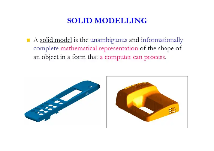
To Be CoveredSome basic concepts of solid model (Data types) Geometric elementsTopologyTwo solid model representation schemes Graph-based modelBoolean modelSome solid modelling methodsBasic Concepts of Solid ModelA solid model has two important sets of information: geometry and topologyThe geometry is a group of geometric elements: faces, edges, and vertices.A face/edge is governed by its mathematical equationsA vertex is specified by its coordinates(x, y, z).The topology specifies the relationship or connectivity among the geometric elementsA solid model is bounded by its faces;A face is bounded by its edges;An edge is bounded by two vertices.An ExampleRepresentation Schemes: Graph-Based Models Has topological structure, with data pointers linking together an object’s faces, edges, and vertices.A solid object: a list of the object’s faces and their respectivesurface equations.The edges of these faces: curve equations, with pointers to their end-point vertices and adjoining faces.The vertices: lists of coordinates, with pointers to the edgesmeeting at each vertex.Two kinds of information –the pointers defining the topology or connectivity between vertices, edges, and faces and numerical data defining curve and surface equations and vertex coordinates.redundant speed upGraph-Based ModelsFor solids represented as planar-faced polyhedron,many simple representation schemes are available, e.g., connectivity matrix for polyhedron.Connectivity matrix (or adjacency matrix): A binary matrix0-element indicates no connectivity exists1-elements indicate connectivity exists between the pair of elements(vertices, edges, or faces).Boolean ModelsIn set theory, there are 3 set operators to form new sets by combining two or more sets in some fashion.Union (∪): C = A∪B: the elements of C are all the elements in A and B.Intersection(∩):D = A ∩B:set D comprised of elements common to both A and B.Difference (–):A –B denotes the set of elements in A that are not also elements in B.Boolean Operators More examplesIf a solid object is represented by the Boolean combination of two or more simpler objects, then the representation is a Boolean model.A Boolean model is a procedural representation.E.g., model D= (A∪B) –CSays nothing quantitative about D.Only specifies the combination of primitive solids.Does not tell the coordinates of the vertices of the new solid or anything about its edges or faces.All we know about D is how to construct it.Also called an unevaluated modelIf we wish to know more (faces,edges, vertices), we have toevaluate the Boolean model.The boundary of D has 32 vertices, 48edges, and18 facesThe binary tree for this modelThe leaf nodes are the primitive solids, with Boolean operators at each internal node and the root.Each internal node combines the two objects immediately below it in the tree, and, if necessary, transforms the result in readiness for the nextoperation.Boolean Models Another exampleSolid Modelling MethodsInstancesUsing scaling factor to transform an existing object.Such transformations affect geometry but not the topology of a shape With limitationsSolid Modelling MethodsSweep RepresentationBased on the notion of moving a point, curve, or surface along some path.The locus of points generated by this process defines a one-, two-, or three-dimensional object.For solid modelling, two ingredients are required –an object(generator) to be moved and a trajectory(director) is an analytically definable path.Solid Modelling MethodsCharacteristics of Sweep RepresentationUsed in many contemporary modelling systems Practical and efficient for modelling constant cross-section mechanical parts Applications Detect potential interference between parts of mechanisms.e.g., a moving object O 1collides with a fixed object O 2if the volume swept by O 1intersects O 2Simulating and analysing material-removal operations in manufacturing e.g., the volume swept by a tool moving along a defined path intersects the raw stock for a part. The intersection volume represents material removed from the part.Solid Modelling MethodsConstructive Solid Geometry(CSG)A modelling method that define complex solids as composition of simplersolids (primitives).Boolean operators are used to execute the composition: union, difference, and intersection.Material can be added as well as removed.CSG representations of objects are ordered binary tree The root represents the final object.Its leaf or terminal nodes are either primitive or transformation data for rigid-body motions.The non-terminal nodes are either Boolean operators or rigid body motions that operate on their two sub-nodes.Each sub-tree of a node (not a transformation leaf) represents a solid resulting from the combination and transformation operations indicatedbelow it.Constructive Solid Geometry (CSG)Example4 leaf nodes represent the primitives π1and π2and the translation ∆x2 internal nodes represent results of the operations (π1-π2) and π2[∆x].The root node represents the final object.Constructive Solid GeometryPrimitivesWhose size, shape, position,and orientation aredetermined by a small set of user-specified parameters (see examples).Boundary Evaluator: Compute the boundary representation (faces, edges, and vertices) of a CSG representationDetermines where component faces are truncated and new edges and vertices are created or deleted.Where boundary elements overlap or coincide, the evaluator merges them into a single element and thus maintains a consistent, non-redundant data structure representing a solid’s boundary.CSG: Some PrimitivesCSG-An ExampleExercise???e the Euler Law to check whether the object shown in Fig. 1 is a valid solid or not;2.Obtain the connectivity matrix between the vertices for the part in Fig. 1;3.Draw a CSG tree for the solid object shown in Fig. 1 by using only “rectangular block”primitive.。
机械solidworks设计流程(中英文版)英文文档内容:The mechanical SolidWorks design process involves several key steps to ensure a successful and accurate design.1.Analysis and Planning: Before starting the design, it is important to analyze the requirements and plan the design accordingly.This includes understanding the purpose of the design, the materials to be used, and any constraints or specifications that need to be considered.2.Modeling: The next step is to create a 3D model of the design using SolidWorks.This involves sketching the initial design, extruding and revolving the sketches to create the 3D geometry, and adding details such as holes, slots, and other features.3.Detailing: Once the 3D model is complete, the next step is to add dimensions, tolerances, and other annotations to the model.This is important for ensuring that the design meets the required specifications and can be accurately manufactured.4.Assembly: If the design consists of multiple parts, they need to be assembled in SolidWorks to ensure that they fit together correctly.This involves creating assembly files and adding the parts to the assembly.5.Simulation and Analysis: SolidWorks provides tools for simulating and analyzing the design to ensure that it meets the requiredperformance specifications.This can include stress analysis, thermal analysis, and motion analysis, among others.6.Documentation: Finally, the design can be documented by creating drawings and other documentation in SolidWorks.This can include detailed part drawings, assembly drawings, and other technical documentation.中文文档内容:机械SolidWorks设计流程包括几个关键步骤,以确保成功和准确的设计。

东北大学智慧树知到“机械工程”《机械CAD-Solidworks实用技术》网课测试题答案(图片大小可自由调整)第1卷一.综合考核(共15题)1.在装配体的FeatureManager设计树中,无法重新排序零部件。
()A、错误B、正确2.拉伸方向总是垂直于草图基准面。
()A.正确B.错误3.钣金是常用的功能。
在SolidWorks中可以将一个薄壁基体零件转化为钣金零件吗?()A、能B、不能C、不知道4.可以直接将ParaSolid的文件以及装配体输入到SolidWorks中。
()A.正确B.错误5.使用绘制圆角工具时,可以用选择实体交叉点上的顶点位置来加入一个草图的圆角。
()A、错误B、正确6.临时轴是在创建圆柱和圆锥体时隐含生成的。
()A、错误B、正确7.如何将一个尺寸从一个视图转移到另外一个视图?()A、选中尺寸后直接拖到新的视图B、选中尺寸后,按下Ctrl键,拖到新的视图中C、选中尺寸后,按下Shift键,拖到新的视图中8.闭合角的边角类型没有下列哪种类型?()A、对接B、重叠C、欠重叠D、相交9.以下哪一项不足以定义基准轴?()A.两点/顶点B.原点C.两平面D.圆柱/圆锥面10.在3D草图的绘制中,不需要选择平面。
在绘制过程中,下列哪个热键可以帮助你切换坐标系?()A.TabB.ShiftC.Ctrl11.使用三个或三个以上轮廓生成放样时,其中间轮廓可以为点。
()A、错误B、正确12.如果没选择模型上的任何面,对一实体零件抽壳,生成一()。
A.闭合的空腔B.按前视图基准面抽壳C.出现错误提示13.如果仅想镜像特征的几何体(面和边线),而并非想求解整个特征,应选择()。
A.源特征B.合并阵列C.几何体阵列14.如果仅想镜像特征的几何体(面和边线),而并非想求解整个特征,应选择()。
A.几何体阵列B.合并阵列C.源特征15.在选择草图工具前,要先选择基准面或平面。
()A.正确B.错误第2卷一.综合考核(共15题)1.在零件中可以将特征进行压缩处理。
第一章测试1【判断题】(6分)CAD/CAE/CAM中CAE的含义是计算机辅助教育。
A.错B.对2【判断题】(6分)CAD的含义是“计算机辅助设计”。
A.对B.错3【判断题】(6分)工程分析技术不是CAD体系中包含的内容。
A.错B.对4【判断题】(6分)屏幕分辨率就是在屏幕上能够分辨图像的清晰度。
A.错B.对5【判断题】(6分)点的几何变换矩阵相乘时顺序不能互换。
A.错B.对6【判断题】(6分)三维形体间的正则并、交、差是实体造型技术中构成物体的基本手段之一。
A.对B.错7【判断题】(6分)使用齐次坐标可以将n维空间的一个点向量唯一的映射到n+1维空间中。
A.对B.错8【判断题】(6分)将某二维图形整体放大2倍,其变换矩阵可写为:A.错B.对9【单选题】(6分)在CAD中多文档的设计环境允许()?A.不能在多文档之间复制、粘贴B.同时打开多个文档,在多个文档上同时工作C.同时打开多个文档,但只能在一个文档上工作D.只能打开一个文档,但可以在多个文档上同时工作10【多选题】(8分)一个简单的CAD系统的硬件组成主要包括()。
A.内存储器(简称内存)B.中央处理器(CPU)C.外存储器D.输入/输出(I/O)接口11【单选题】(6分)AutoCAD软件是()公司的产品。
A.法国的达索B.美国的PTCC.德国的西门子D.美国的Autodesk12【单选题】(6分)CAD技术发展的趋势是:网络化、集成化、标准化及()等。
A.信息化B.智能化C.实用化D.一体化13【多选题】(8分)下列设备哪些属于CAD硬件设备?A.三坐标测量仪B.耳机C.3D打印机D.立体眼镜E.数码相机14【单选题】(6分)A点的图形1变换到B点的图形2,以下关于图形变换矩阵的叙述正确的是。
矩阵1:矩阵2:A.第一步平移矩阵是矩阵1B.图形变换矩阵是平移矩阵乘以旋转矩阵C.如果A、B点关于O点对称,则图形变换过程可以是:图形1先关于O点镜像,然后再缩放图形。
第四章:实体自由成型制造与快速原文制造4.1 实体自由成形制造方法可以用几种制造方法将CAD信息转换为原型物体。
自1987年以来,又出现了几种新的技术来完成这一转换。
就在1987年,3D系统公司(3D Systems Inc.)推出了立体光刻(SLA)这一技术。
在随后的5年里,又出现了几种与之相竞争的技术。
这一组新技术一般通称为实体自由成形制造(solid freeform fabrication,SFF)。
正如大多数新技术都要经历第2章所描述的市场接纳s形曲线一样,实体自由成形制造领域经历了相当长的广告宣传阶段。
其他用来描述实体自由成形制造这一技术的词汇还包括:·需求中的零件(part on demand);·从艺术到零件(from art to part);·桌面上制造(desktop manufacturing);·快速成形(rapid prototyping)。
在撰写本书时,专门从事原型制造的公司已将立体光刻(SI,A)、选择性激光烧结(SI。
S)、熔融沉积制造(FDM)和分层实体制造(LOM)用于日常商业活动中。
以玉米淀粉、塑料和陶瓷为材料的三维印刷(3DP)也正进入商业应用。
还有几种原型制造方法虽具有潜力,但并没有以盈利目的被第三方普遍采用。
铸造是一个特例,它仍然被用于单件原型制造。
另外,当用立体光刻做好模具后,采用铸造进行10~500批量范围的生产仍然韭常绎济.机加T巾.用于单件或几件批量的原型制造。
非。
吊经价。
剖L川U上也川丁半什域儿lT丁LL里口Y怀型rⅡu坦。
4.1.1 实体自由成形制造与-陕速成形技术总结用于日常商业性活动的包括:立体光刻;选择性激光烧结;分层实体制造;熔融沉积制造。
处于研究与开发阶段的包括:以玉米淀粉、塑料和陶瓷为材料的三维印刷;以塑料为材料并由机加工来铣平的三维印刷;实体磨削固化(SGC,与SLA类似);形状沉积制造(SDM,分层叠加与分层递减的结合)非实体自由成形制造(传统方法)包括:机加工;铸造。
Chapter 4 Modeling of Solids4.1 IntroductionSo far we have represented objects with wireframe and surface modeling. Another method of geometric modeling is to use vertices, edges and surfaces to define a solid. Solid modeling systems allow users to create, store and manipulate unambiguous models of physical solid objects, In recent years, solid modeling has become the prevalent and favorable tool for applications in design and manufacturing.Some of the major advantages of solid modeling are listed here.(1) Visualization of components in 3D space or in realistic surroundings can be made easier.(2) Solid models can be used as data input to other systems, like FE-systems, integration between solid model and FE-model provides great possibility to cut short the product development process.(3) Components can be machined straight from the files created by these systems.A solid model contains both the geometry data and topological data. Topological data describe the connectivity and associability of the object entities. Solid model generation is often not unique, that is, there are often several different ways to create a solid model. CAD users need to generate solid models which can make the computer storage small and suited for later utilize.Boundary representation (B-rep) and Constructive Solid Geometry (CSG) are two most popular schemes for solid modeling. B-reps are based on the topological notion that an object is bounded by faces. CSG is based on that an object can be divided intoa set of primitives. Table 4.1 shows some widely used CAD systems.4.2 Solid RepresentationMost geometric objects we see every day are solids. Solids can be very simple like a cube or very complex like a piston engine. To be processed by computers, solids must have some representations that can describe the geometry and characteristics completely. In fact, a good representation should address the following issues.①Domain: While no representation can describe all possible solids, a representation should be able to represent a useful set of geometric objects. Domain should give a useful set of physical objects that can be represented.②Unambiguity: A solid should be represented without any doubt. An unambiguous representation is usually referred to as a complete one. Figure 4.1 shows an example of ambiguous solids.③Uniqueness: There is only one way to represent a particular solid. If a representation is unique, then it is easy to determine if two solids are identical since one can just compare their representations.④Accuracy: A representation is said accurately if no approximation is required.⑤Validity: A representation should not create any invalid or impossible solids. More precisely, a representation will not represent an object that does not correspond to a solid.⑥Closure; Solids will be transformed and used with other operations such as union and intersection, "Closure" means that transforming a valid solid always yields a valid solid.⑦Compactness and efficiency: A good representation should be compact enough for saving space and allow for efficient algorithms to determine desired physical characteristics.There are different methods to create models, such as half-space, boundary representation (B-rep), constructive solid geometry (CSG), sweeping, analytic solid modeling, cell decomposition. Following concepts are important in solid modeling: solid primitives, Boolean operations, geometry closure and regularized set operations.(1) PrimitivesSolid primitives are frequently used in solid modeling. CAD/CAM systems provide various primitives such as block, cylinder, cone, and sphere. Figure 4.2 shows an example of these solid entities.(2) Boolean operationsUnion, difference, complement and intersection are essential Boolean operations. Figure 4.3 shows Boolean operations used in the solid modeling. Boolean operations are intuitive to use and easy to understand, and they provide for rapid manipulation of large amounts of data. Because of this, Boolean operations are also used in many non-CSG systems.(3) Interior, exterior and closureWe need the concepts of interior, exterior and closure to understand regularized Boolean operators. Intuitively, the interior of a solid consists of all points lying inside of the solid; the closure consists of all interior points and all points on the surface of solids; and the exterior of a solid is the set of all points that do not belong to the closure.A open ball with centre (a, b, c) and radius r consists of all points that satisfy the following relation,(x-a)2+(y-b)2+(z-c)2<r2A point P is an interior point of a solid S if there exists a radius r such that the open ball with centre P and radius r is contained in the solid S. The set of all interior points of solid S is the interior of S, written as int (S). Based on this definition, the interior of an open ball is the open ball itself.On the other hand, a point Q is an exterior point of a solid S if there exists a radius r such that the open ball with centre Q and radius r does not intersect S. The set of all exterior point of solid S is the exterior of solid S, written as ext(S).Those points that are neither in the interior nor in the exterior of a solid S constitutes the boundary of solid S, written as b(S). Therefore, the union of interior, exterior and boundary of a solid is the whole space.The closure of a solid S is defined to be the union of the interior and the boundary of S, written as closure (S). Or, equivalently, the closure of solid S contains all points that are not in the exterior of S.(4) Regularized set operationsWhen set operations are used in geometry modeling, unwanted geometry may begot. In Fig. 4.4, two cubes touch each other and their intersection is a rectangle shown on the right. A rectangle is not a three-dimensional object and hence not a solid.To eliminate these lower dimensional branches, the three set operations are regularized as follows. The idea is simple.Compute the result as usual and lower dimensional components may be generated. Compute the interior of the result. This step removes all the lower dimensional components.Compute the closure of the result obtained in the above step. This adds the boundary back.Let op* be the regularized operator and let A and B be two solids. Then, A∪* B , A ∩*B and A-* B can be defined mathematically based on the above description.A∪* B - c1osure(int(the set union of A and B))A∩*B - c1osure(int(the set intersection of A and B))A-* B - c1osure (int (the set difference of A and B))Based on this definition, the intersection of the two cubes shown in Fig. 4.4 is empty. The intersection of these two cubes is a rectangle, which is a two-dimensional object and has no interior. Hence, after taking interior (i.g. , int()), we get an empty set, whose closure is also empty. Consequently, the intersection is empty.4.3 Boundary RepresentationBoundary models have a hierarchical format. As mentioned earlier, B-reps describe objects bounded by a set of faces. Each face has its underlying closed (continuous) and oriented surface as shown in Fig. 4.5 and the face is bounded by edges. Each edge is bounded by vertices. A boundary model of an object is comprised of faces, edges and vertices.The surface of a solid consists of a set of well-organized faces, each of which is a piece of some surface (e. g., a surface patch). Faces may share vertices and edges that are curve segments. Therefore, a B-rep is an extension to the wireframe model by adding face information to the later.The orientation of each face is important. Normally, a face is surrounded by a set of vertices. Using the right-handed rule, the ordering of these vertices for describing a particular face must guarantee that the normal vector of that face is pointing to the exterior of the sol-id. Normally, the order is counter clockwise. Therefore, by inspecting normal vectors one can immediately tell the inside and outside of a solid under B-rep. This orientation must be done for all faces.The database of a boundary model contains both topological and geometric data. Topological data provide the relationships among vertices, edges and faces similar to that used in a wireframe model. In addition to connectivity, topological information also includes orientation of edges and faces. Geometric information is usually equations of the edges and faces. Topology is created by performing Euler operations and geometry is created by per-form Euclidean calculations. Both the topological and geometry validity should be checked to avoid nonsense object. Euler operators also provide designers with drafting functionality.Boolean operators are often used to create and edit models. Since B-rep requiresexplicit representation of the boundary of the solid, boundaries must be evaluated after the operation. For CSG model, the Boolean operation is simply an addition to the CSG tree.The main advantage of B-rep is its ability to construct solids that are difficult to build u-sing primitives. The main disadvantage is that it requires large amounts of storage because it stores the boundary explicitly.4.3.1 Euler FormulaObjects that are often encountered in engineering are polyhedral or curved objects. Figure 4.6 shows examples of polyhedral.Eu1er (or Euler-Poincare) law is that a polyhedron is topologically valid if they satisfy the following equation,F-E+V-L=2(B-G) (4.1) Where F, E, V, L, B and G are the number of faces, edges, vertices, faces’ inner loop bodies and genus (handles or through holes) respectively. For a simple polyhedron, we have: F-E+V=2.Euler law can be used to check the object’s validity, the system commands (Euler operators) are based on Euler law and thus ensure the validity simultaneously. Euler law given above applies to closed polyhedral objects. For open polyhedron, we have: P-E+V-L=B-G (4.2)If objects have curved surface, such as cylinders and spheres, Euler law is still valid. Topologically, one can always stretch curved edges and faces so that they become flat without changing the relationships among them.4.3.2 Euler OperatorsOnce a polyhedron model is available, one might want to edit it by adding or deleting vertices, edges and faces to create a new polyhedron. These operations are called Euler operators.Recall from the discussion of the Euler formula that the following holds for all polyhedra:V-E+F-(L-F)-2(B-G) =0 (4.3) Based on this relation, some Euler operators have been selected for editing a polyhedron so that the Euler formula is always satisfied. There are two groups of such operators: the Make group and the Kill group. Operators starting with M and K are operators of the Make and Kill groups, respectively.Euler operators are written as Mxyz and Kxyz for operations in the Make and Kill groups, respectively, where x, y and z are elements of the model (e.g., a vertex, edge, face, loop, shell and genus). For example, MEV means adding an edge and a vertex while KEV means deleting an edge and a vertex. The user is not free to construct faces, edges or vertexes. For example, there are no such operators such as ME, MV or MF as they violate Euler law.Every topologically valid polyhedron can be constructed from an initial polyhedron by a finite sequence of Euler operators. Therefore, Euler operators are powerful operations.4.3.2.1 The Make Group of Euler OperatorsThe Make group consists of four operators for adding some elements into theexisting model creating a new one, and a Make-Kill operator for adding and deleting some elements at the same time. The operators are as shown in Table 4. 2.Table 4.2 shows the change of values of V, E, F, L. B and C. Note that adding a face produces a loop, the outer loop of that face. Therefore, when F is increased, L should also be increased. This new loop and the new face will cancel each other in the sub expression of L-F. Please verify that none of these operators would cause the Euler formula to fail.MBFV is often used to begin constructing the boundary models, so it could be through as the first vertex of the model. Table 4.3 illustrates the way of using Euler operators to construct a tetrahedron, in seven steps or seven Euler operators a tetrahedron is created.MBG simply makes a body with a hole. After this, one can add vertices, edges, faces, and loops. There must be loops, because the new hole penetrates at least one face.MEKL makes an edge and at the same time kills a loop. A commonly used MEKL is adding an edge connecting the outer loop and the inner loop of a face. In this case, the number of edges E is increased by 1and the number of loops L is decreased by 1 since that loop is killed.Higher level Euler operators can be developed, such as MCUBE (create a cube), MCYL(create a cylinder).4.3.2.2 The Kill Group of Euler OperatorsThe Kill group just performs the opposite of what the Make group does. In fact, replacing the M and K in all Make operators with K and M, respectively, would get the operators of the Kill group. Therefore, the Kill group consists of the five operators as shown in Table 4.4.With these operators, one can start with a tetrahedron and reduce it to nothing. These operators are the opposites of the Make operators. The advantages of Euler operators are that they ensure creating valid topology and reasonable is simple. Euler operators offer a mechanism to check the topological validity of the models. However the models are not unique because the boundary of any object can be divided into faces, edges and vertices in many ways. Euler operators are difficult for designers to use and usually not available to users at interface, only exist internal to software. Earlier user interfaces used commands such as "make edge/face" or "kill edge/face", although such interfaces are not convenient. Object-oriented (feature-based) user interfaces are more acceptable by users. For example, command "create hole" is better than "subtract cy-linder".4.3.3 The Winged-edge Data StructureThe winged data structure is useful data structure in B-rep. In this structure, all the adjacency relations of each edge are described explicitly. The winged-edge data structure uses edges to keep track almost everything.For each edge, the following information is important: vertices of this edge, its left and right faces, the predecessor and successor of this edge when traversing its left face, the predecessor and successor of this edge when traversing its right face.Each entry in the edge table contains above information mentioned earlier: edgename, start vertex and end vertex, left face and right face, the predecessor and successor edges for left and right faces. Note that clockwise ordering (viewing from outside of the polyhedron) is used for traverse.Figure 4.9 shows the information for the entry of edge a. The four edges b, c, d and e 1are the wings of edge a an d hence edge a is “winged”.Figure 4.10 is a tetrahedron with four vertices A, B, C and D, six edges a, b, c, d, e and f, and four faces 1,2,3 (back) and 4 (bottom), whose edges are listed in Table 4.5. The winged-edge data structure requires two more tables, the vertex table and the face table. The vertex table has one entry for each vertex, which contains an edge, that is incident to this vertex. The face table has one entry for each face, which contains an edge i.e. one of this face's boundary edges.With this data structure, one can easily answer the question; which vertices, edges, faces are adjacent to each face, edge, or vertex. However, it may take longer time to answer other adjacency queries. Note also that once the numbers of vertices, edges and faces are known, the size of all three tables are fixed and will not change.If some faces of a solid have holes, the above form of winged-edge data structure does not work. There are two ways for resolving this problem:(1) For a face with inner loops, the outer boundary is ordered clockwise, while its inner loops, if any, are ordered counter clockwise as shown in Fig. 4.11.(2) Alternatively, a special auxiliary edge can be us ed to join each hole’s boundary to the outer boundary, as shown in Fig. 4. 12. Since each edge will have the same face on both of its sides, it can be easily identified.4.4 Constructive Solid GeometryA physical object can be divided into a set of primitives and can be combined by Boolean operations. CSG model is based on this principle.CSG is a solid modeling method that combines simple solid shapes called primitives to build more complex models, using the Boolean operators.The database of a CSG model, similar to B-rep, stores its topology and geometry. Topology is created via the regularized Boolean operations that combine primitives. Checking the used primitives can ensure the validity. The geometry stored in the database of a CSG includes configuration parameters of its primitives and rigid motion.A CSG model requires minimum storage to store solid definitions (graphs/trees) , as it does not store explicitly the faces, edges and vertices. It evaluates them whenever they are needed, e. g. generation of line drawings. This makes it slow to retrieve the model because it has to build a boundary. Due to the same reason, it is also slow to generate wireframes.4.4.1 CSG PrimitivesThe standard CSG primitives consist of the block (i.e. cube), triangular prism, sphere, cylinder, cone and torus as shown in Fig. 4. 13. All these primitives have their own local coordinate systems. These six primitives must be instantiated by the user to be used in his/her design. Moreover, the instantiated primitive may require transformations such as scaling translation and rotation to be positioned at the desired place.1. Block. A block is defined by its width, height and depth. The signs of W, H andD can be negative.2. Cylinder. This primitive is defined by its radius (or diameter) R and length H. the length H is usually taken along the direction of the z L axis. H can be positive or negative.3. Cone. The indata to define a cone is its base radius R. top radius (for truncated cone), and height H.4. Sphere. The indata is its radius.5. Wedge. A right-angled wedge is defined by its height H, width W. and base depthD.6. Torus. This primitive is generated by the revolution of a circle about an axis. It can be defined by the radius of its body R1, and the radius of the centre line of the torus body R2.4.4.2 Boolean OperatorsA solid can be considered as the result of applying Boolean operators to a set of instantiated and transformed CSG primitives. However, simple set operators may create problems as discussed in regularized Boolean operators. Let us just use set operations on following example.Let us construct a bracket with a hole, as shown on the right-most of Fig. 4.14. We start with two instantiations of blocks and one instantiation of a cylinder (the left-most figure). These three instantiations are then rotated or/and transformed to their desiredpositions. The final product is obtained by subtracting the cylinder from block 1, and then computing the union with block 2.Please note that the design of the above solid is not unique. For example, one may compute the union of block l and block 2, and then compute the difference.4.4.3 CGS TreeTrees and graphs are used for the CSG representation as in winged-edge structure usedin B-rep.A tree is defined as a data structure accessed from the root node. Each node is either a leaf or an internal node. An internal node has one or more child nodes and is called the parent of its child nodes. Figure 4.15 shows a tree. A binary tree is defined as a tree with at most two children for each node.A CSG tree is defined as an inverted ordered binary tree whose leafs are primitives and interior nodes are regularized set operations.The procedure to build the bracket with Boolean operators can be written as: union(diff(trans(block 1), trans(cylinder)), trans(block2)) , where union(A,B) and diff(A,B) are the union and difference of A and B, and trans( ) indicates appropriate transformations This procedure can be converted to a CSG tree of the design, as shown in Fig. 4. 16.In fact, every solid constructed using the CSG technique has a corresponding CSG tree. The expression of the CSG tree is a representation of the final design.The total number of nodes in a CSG tree of a solid depends on the number of primitives the solid is decomposed to. If a solid has n primitives, then there are (n-1) Boolean operations for a total of (2n-1) nodes in its tree.Balanced trees are preferred in various applications. A balanced tree is defined as a tree whose left and right subtrees have almost an equal number of nodes, that is, the absolute value of the difference (n L-n R) is as small as possible, where (n L+ n R) = 2n-2. The general rule to create balanced trees is to start to build the model from an almost central position and branch out in two opposite directions.To transverse a tree means to pass through the tree and visit each of its nodes. There are mainly three methods to transverse a CSG tree: preorder, in order and postorder. To transverse a tree in preorder, we have he following recursive definition:①Visit the root;②Transverse the left subtree in preorder;③Transverse the right subtree in preorder.Then the reversed preorder is defined by reversing the above operations, that is, visit the right subtree, then the left subtree, and the rootThe order to transverse a tree in inorder is,①Transverse the left subtree in inorder;②Visit the root;③Transverse the right subtree in inorder.And the order to transverse a tree in postorder is,①Transverse the left subtree in postorder;②Transverse the right subtree in postorder.③Visit the rootTo get the reversed inorder and postorder, operations in respective method are reversed.4.5 Sweep GenerationThere are three types of sweep operation: linear, nonlinear and hybrid sweeps. Path in a linear sweep is linear or circular vector describe by a linear parametric equation. Path in a nonlinear sweep is a curve described by a higher-order equation. Hybrid sweep combines linear and/or nonlinear sweep via set operations.Many commands in CAD/CAM software are based on sweeping.4.6 Modeling of Analytic SolidA short introduction of analytic solid is given below. The definition of a parametric solid can be extended from curves and surfaces. Points in the interior or on the boundary of a solid are given by[][])w ,v ,u (z )w ,v ,u (y )w ,v ,u (x z y x )v ,u (P ==,w w w ,v v v ,u u u max min max min max min ≤≤≤≤≤≤ (4.4) As shown in Fig. 4.18 hyperpatch is a geometric entity, which defines a volume in 3Dspace. It is represented internally as a parametric tricubic solid.A tricubic hyperpatch can be given by∑∑∑====30i 30j 30k k j i ijk w v u C )w ,v ,u (P ,1w 0,1v 0,1u 0≤≤≤≤≤≤ (4.5)By substituting proper value of the parameters, we can get face surface, edge curve and corner vertices. For example, P (0,u,w) and P(1,u, w) are two faces, P(u, 0, 0) is an edge and P(0, 0, 0) is a vertex. The tricubic hyperpatch has the same disadvantages of cubic curve and bicubic surface, and it even requires the input of w v u /P 3∂∂∂∂.A tricubic Bezier Hyperpatch is defined by the following equation,∑∑∑====30i 30j 30k k j ijk )w (B )v (B )u (Bi P )w ,v ,u (P (4.6)4.7 Solid Manipulation(1) DisplayingThere are two methods to display a solid; wire display and shaded display. Shaded display provides realistic visual images. Shaded images can be generated from B-reps by visible-surface algorithms. Shading can be performed from CSG by means of ray-casting or z-buffer algorithms. More on shading will be discussed in Chapter 5.(2) Evaluating points, curves and surfaces on solidEvaluating points and curves on solids can be viewed as intersection problem. Points and curves are generated by finding curve/solid and surface/solid intersections. Evaluating surfaces on a solid can be regarded as extracting the underlying surfaces of the solid faces. These surfaces can be bonded by the proper solid edges oruser-defined boundaries.(3) SegmentationSegmentation of a solid is to split it into two or more valid subsolids. Each resulting subsolid should have its own topology and geometry, In a B-rep model, new vertices, edges and faces are created, In a CSG model, splitting the solid would also require splitting its CSG graph and tree.(4) Trimming and intersectionTrimming a solid is using trimming boundaries to split a solid and removing the portions outside these boundaries. Intersection can be performed by Boolean operations.(5) TransformationSolids can be translated, rotated by using homogeneous transformation.(6) EditingEditing a solid involves changing its existing topological and geometrical information. For CGS models, graphs and trees are used to edit the model. For B-rep model, a graph or tree can be created and modified.。