SCE with Maximum Flow in SDN and application to the next-generztion cellular network architecture
- 格式:pptx
- 大小:344.63 KB
- 文档页数:7
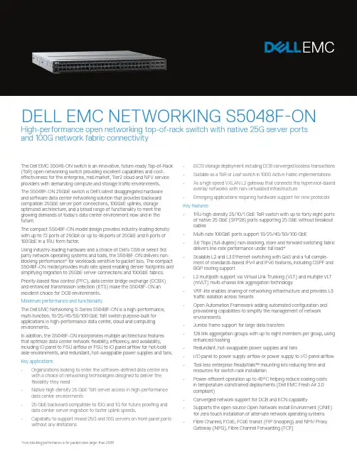
The Dell EMC S5048-ON switch is an innovative, future-ready T op-of-Rack (T oR) open networking switch providing excellent capabilities and cost-effectiveness for the enterprise, mid-market, Tier2 cloud and NFV service providers with demanding compute and storage traffic environments.The S5048F-ON 25GbE switch is Dell’s latest disaggregated hardware and software data center networking solution that provides backward compatible 25GbE server port connections, 100GbE uplinks, storage optimized architecture, and a broad range of functionality to meet the growing demands of today’s data center environment now and in the future.The compact S5048F-ON model design provides industry-leading density with up to 72 ports of 25GbE or up to 48 ports of 25GbE and 6 ports of 100GbE in a 1RU form factor.Using industry-leading hardware and a choice of Dell’s OS9 or select 3rd party network operating systems and tools, the S5048F-ON delivers non-blocking performance* for workloads sensitive to packet loss. The compact S5048F-ON model provides multi rate speed enabling denser footprints and simplifying migration to 25GbE server connections and 100GbE fabrics. Priority-based flow control (PFC), data center bridge exchange (DCBX) and enhanced transmission selection (ETS) make the S5048F-ON an excellent choice for DCB environments.Maximum performance and functionalityThe Dell EMC Networking S-Series S5048F-ON is a high-performance, multi-function, 10/25/40/50/100 GbE T oR switch purpose-built for applications in high-performance data center, cloud and computing environments.In addition, the S5048F-ON incorporates multiple architectural features that optimize data center network flexibility, efficiency, and availability, including IO panel to PSU airflow or PSU to IO panel airflow for hot/cold aisle environments, and redundant, hot-swappable power supplies and fans. Key applications• Organizations looking to enter the software-defined data center era with a choice of networking technologies designed to deliver theflexibility they need• Native high-density 25 GbE T oR server access in high-performance data center environments• 25 GbE backward compatible to 10G and 1G for future proofing and data center server migration to faster uplink speeds.• Capability to support mixed 25G and 10G servers on front panel ports • iSCSI storage deployment including DCB converged lossless transactions • Suitable as a T oR or Leaf switch in 100G Active Fabric implementations • As a high speed VXLAN L2 gateway that connects the hypervisor-based overlay networks with non-virtualized infrastructure• Emerging applications requiring hardware support for new protocols Key features• 1RU high-density 25/10/1 GbE T oR switch with up to forty eight ports of native 25 GbE (SFP28) ports supporting 25 GbE without breakout cables• Multi-rate 100GbE ports support 10/25/40/50/100 GbE• 3.6 Tbps (full-duplex) non-blocking, store and forward switching fabric delivers line-rate performance under full load*• Scalable L2 and L3 Ethernet switching with QoS and a full comple-ment of standards-based IPv4 and IPv6 features, including OSPF and BGP routing support• L2 multipath support via Virtual Link Trunking (VLT) and multiple VLT (mVLT) multi-chassis link aggregation technology• VRF-lite enables sharing of networking infrastructure and provides L3 traffic isolation across tenants• Open Automation Framework adding automated configuration and provisioning capabilities to simplify the management of networkenvironments• Jumbo frame support for large data transfers• 128 link aggregation groups with up to eight members per group, using enhanced hashing• Redundant, hot-swappable power supplies and fans• I/O panel to power supply airflow or power supply to I/O panel airflow • T ool-less enterprise ReadyRails™ mounting kits reducing time and resources for switch rack installation• Power-efficient operation up to 45°C helping reduce cooling costs in temperature-constrained deployments (Dell EMC Fresh Air 2.0compliant)• Converged network support for DCB and ECN capability• Supports the open source Open Network Install Environment (ONIE) for zero touch installation of alternate network operating systems• Fibre Channel, FCoE, FCoE transit (FIP Snooping) and NPIV ProxyDELL EMC NETWORKING S5048F-ONHigh-performance open networking top-of-rack switch with native 25G server ports and 100G network fabric connectivity**future deliverable48 line-rate 25 Gigabit Ethernet SFP28 ports6 line-rate 100 Gigabit Ethernet QSFP28 ports1 RJ45 console/management port with RS232signaling1 Micro-USB type B optional console port1 10/100/1000 Base-T Ethernet port used asmanagement port1 USB type A port for the external mass storage Size: 1 RU, 1.72 h x 17.1 w x 18” d(4.4 h x 43.4 w x 45.7 cm d)Weight: 22lbs (9.98kg)ISO 7779 A-weighted sound pressure level: 59.6 dBA at 73.4°F (23°C)Power supply: 100–240 VAC 50/60 HzMax. thermal output: 1956 BTU/hMax. current draw per system:5.73A/4.8A at 100/120V AC2.87A/2.4A at 200/240V ACMax. power consumption: 573 Watts (AC)T yp. power consumption: 288 Watts (AC) with all optics loadedMax. operating specifications:Operating temperature: 32° to 113°F (0° to 45°C) Operating humidity: 10 to 90% (RH), non-condensingFresh Air Compliant to 45°CMax. non-operating specifications:Storage temperature: –40° to 158°F (–40° to70°C)Storage humidity: 5 to 95% (RH), non-condensing RedundancyT wo hot swappable redundant power suppliesHot swappable redundant fansPerformanceSwitch fabric capacity: 3.6TbpsForwarding capacity: Up to 2,678 MppsPacket buffer memory: 22MB (16MB supported in initial release)CPU memory: 8GBMAC addresses: 132K (in scaled-l2-switch mode) ARP table: 82K (in scaled-l3-hosts mode)IPv4 routes: Up to 128KIPv6 routes: Up to 64K (20k currently supported) Multicast hosts: Up to 8KLink aggregation: 128 groups, 32 members per LAG groupLayer 2 VLANs: 4KMSTP: 64 instancesLAG Load Balancing: Based on layer 2, IPv4 or IPv6 header, or tunnel inner header contentsQoS data queues: 8QoS control queues: 12QoS: 1024 entries per TileIngress ACL: 1024 entries per TileEgress ACL: 1k entries per TilePre-Ingress ACL: 1k entries per TileIEEE Compliance802.1AB LLDP802.1D Bridging, STP802.1p L2 Prioritization802.1Q VLAN T agging, Double VLAN T agging,GVRP802.1Qbb PFC802.1Qaz ETS802.1s MSTP802.1w RSTP802.1X Network Access Control802.3ab Gigabit Ethernet (1000BASE-T) orbreakout802.3ac Frame Extensions for VLAN T agging 802.3ad Link Aggregation with LACP 802.3ba 40 Gigabit Ethernet (40GBase-SR4,40GBase-CR4, 40GBase-LR4, 100GBase-SR10, 100GBase-LR4, 100GBase-ER4) onoptical ports802.3bj 100 Gigabit Ethernet802.3u Fast Ethernet (100Base-TX) on mgmtports802.3x Flow Control802.3z Gigabit Ethernet (1000Base-X) with QSAANSI/TIA-1057 LLDP-MEDForce10 PVST+Jumbo MTU support 9,416 bytesLayer2 Protocols4301 Security Architecture for IPSec*4302 IPSec Authentication Header*4303 ESP Protocol*802.1D Compatible802.1p L2 Prioritization802.1Q VLAN T agging802.1s MSTP802.1w RSTP802.1t RPVST+802.3ad Link Aggregation with LACPVL T Virtual Link T runkingRFC Compliance768 UDP793 TCP854 T elnet959 FTP1321 MD51350 TFTP2474 Differentiated Services2698 T wo Rate Three Color Marker3164 Syslog4254 S SHv2General IPv4 Protocols791 I Pv4792 ICMP826 ARP1027 Proxy ARP1035 DNS (client)1042 Ethernet Transmission1191 Path MTU Discovery1305 NTPv41519 CIDR1542 BOOTP (relay)1858 IP Fragment Filtering2131 DHCP (server and relay)5798 V RRP3021 31-bit Prefixes3046 D HCP Option 82 (Relay)1812 Requirements for IPv4 Routers1918 Address Allocation for Private Internets2474 Diffserv Field in IPv4 and Ipv6 Headers2596 A ssured Forwarding PHB Group3195 Reliable Delivery for Syslog3246 E xpedited Assured Forwarding4364 V RF-lite (IPv4 VRF with OSPF and BGP)*General IPv6 Protocols1981 Path MTU Discovery*2460 I Pv62461 Neighbor Discovery*2462 S tateless Address AutoConfig2463 I CMPv62675 Jumbo grams3587 Global Unicast Address Format4291 IPv6 Addressing2464 T ransmission of IPv6 Packets over EthernetNetworks2711 IPv6 Router Alert Option4007 I Pv6 Scoped Address Architectureand Routers4291 IPv6 Addressing Architecture4861 Neighbor Discovery for IPv64862 I Pv6 Stateless Address Autoconfiguration5095 Deprecation of T ype 0 Routing Headers in IPv6IPv6 Management support (telnet, FTP, TACACS,RADI US, SSH, NTP)RIP1058 RIPv12453 R I Pv2OSPF (v2/v3)1587 NSSA (not supported in OSPFv3)1745 OSPF/BGP interaction1765 OSPF Database overflow2154 MD52328 OSPFv22370 Opaque LSA3101 OSPF NSSA3623 O SPF Graceful Restart (Helper mode)*BGP1997 Communities2385 M D52439 R oute Flap Damping2545 B GP-4 Multiprotocol Extensions for IPv6I nter-Domain Routing2796 Route Reflection2842 C apabilities2858 M ultiprotocol Extensions2918 Route Refresh3065 C onfederations4271 BGP-44360 E xtended Communities4893 4-byte ASN5396 4-byte ASN Representation5492 C apabilities AdvertisementMulticast1112 IGMPv12236 I GMPv23376 IGMPv3MSDPPIM-SMPIM-SSMNetwork Management1155 SMIv11157 SNMPv11212 Concise MIB Definitions1215 SNMP Traps1493 Bridges MIB1850 OSPFv2 MIB1901 Community-Based SNMPv22011 IP MIB2096 I P Forwarding T able MIB2578 SMI v22579 T extual Conventions for SMIv22580 C onformance Statements for SMIv22618 RADIUS Authentication MIB2665 E thernet-Like Interfaces MIB2674 Extended Bridge MIB2787 VRRP MIB2819 RMON MIB (groups 1, 2, 3, 9)2863 I nterfaces MIB3273 RMON High Capacity MIB3410 SNMPv33411 SNMPv3 Management Framework3412 Message Processing and Dispatching for theSimple Network Management Protocol (SNMP)3413 SNMP Applications3414 User-based Security Model (USM) forSNMPv33415 VACM for SNMP3416 SNMPv23417 Transport mappings for SNMP3418 SNMP MIB3434 R MON High Capacity Alarm MIB3584 C oexistance between SNMP v1, v2 and v3 4022 I P MIB4087 IP Tunnel MIB4113 UDP MIB4133 Entity MIB4292 M IB for IP4293 M IB for IPv6 T extual Conventions4502 R MONv2 (groups 1,2,3,9)5060 PIM MIBANSI/TIA-1057 LLDP-MED MIBDell_ITA.Rev_1_1 MIBdraft-ietf-idr-bgp4-mib-06 BGP MIBv1IEEE 802.1AB LLDP MIBIEEE 802.1AB LLDP DOT1 MIBIEEE 802.1AB LLDP DOT3 MIB sFlowv5 sFlowv5 MIB (version 1.3)DELL-NETWORKING-BGP4-V2-MIB(draft-ietf-idr-bgp4-mibv2-05)DELL-NETWORKING-IF-EXTENSION-MIBDELL-NETWORKING-LINK-AGGREGATION-MIB DELL-NETWORKING-COPY-CONFIG-MIBDELL-NETWORKING-PRODUCTS-MIBDELL-NETWORKING-CHASSIS-MIBDELL-NETWORKING-SMIDELL-NETWORKING-TCDELL-NETWORKING-TRAP-EVENT-MIBDELL-NETWORKING-SYSTEM-COMPONENT-MIB DELL-NETWORKING-FIB-MIBDELL-NETWORKING-FPSTATS-MIBDELL-NETWORKING-ISIS-MIBDELL-NETWORKING-FIPSNOOPING-MIBDELL-NETWORKING-VIRTUAL-LINK-TRUNK-MIB DELL-NETWORKING-DCB-MIBDELL-NETWORKING-OPENFLOW-MIBDELL-NETWORKING-BMP-MIBDELL-NETWORKING-BPSTATS-MIBSecuritydraft-grant-tacacs-02 TACACS+2404 The Use of HMACSHA-1-96 within ESP and AH 2865 R ADI US3162 Radius and IPv63579 RADIUS support for EAP3580 802.1X with RADIUS3768 EAP3826 A ES Cipher Algorithm in the SNMP User Base Security Model4250, 4251, 4252, 4253, 4254 SSHv24301 Security Architecture for IPSec4302 I PSec Authentication Header4807 IPsecv Security Policy DB MIBData center bridging802.1Qbb Priority-Based Flow Control802.1Qaz Enhanced Transmission Selection (ETS)* Data Center Bridging eXchange (DCBx)DCBx Application TLV (iSCSI, FCoE*) Regulatory complianceSafetyUL/CSA 60950-1, Second EditionEN 60950-1, Second EditionIEC 60950-1, Second Edition Including All National Deviations and Group DifferencesEN 60825-1 Safety of Laser Products Part 1: Equipment Classification Requirements and User’s GuideEN 60825-2 Safety of Laser Products Part 2: Safety of Optical Fibre Communication SystemsIEC 62368-1FDA Regulation 21 CFR 1040.10 and 1040.11 Emissions & ImmunityFCC Part 15 (CFR 47) (USA) Class AICES-003 (Canada) Class AEN55032: 2015 (Europe) Class ACISPR32 (International) Class AAS/NZS CISPR32 (Australia and New Zealand) Class AVCCI (Japan) Class AKN32 (Korea) Class ACNS13438 (T aiwan) Class ACISPR22EN55022EN61000-3-2EN61000-3-3EN61000-6-1EN300 386EN 61000-4-2 ESDEN 61000-4-3 Radiated ImmunityEN 61000-4-4 EFTEN 61000-4-5 SurgeEN 61000-4-6 Low Frequency Conducted Immunity NEBSGR-63-CoreGR-1089-CoreATT-TP-76200VZ.TPR.9305RoHSRoHS 6 and China RoHS compliantCertificationsJapan: VCCI V3/2009 Class AUSA: FCC CFR 47 Part 15, Subpart B:2009, Class A Warranty1 Year Return to DepotLearn more at /NetworkingIT Lifecycle Servicesfor NetworkingExperts, insights and easeOur highly trained experts, withinnovative tools and proven processes,help you transform your IT investments into strategic advantages.Plan & DesignLet us analyze yourmultivendor environmentand deliver a comprehensivereport and action plan to buildupon the existing network andimprove performance.Deploy & IntegrateGet new wired or wirelessnetwork technology installedand configured with ProDeploy.Reduce costs, save time, andget up and running fast.EducateEnsure your staff builds theright skills for long-termsuccess. Get certified on DellEMC Networking technologyand learn how to increaseperformance and optimizeinfrastructure.Manage & SupportGain access to technical expertsand quickly resolve multivendornetworking challenges withProSupport. Spend less timeresolving network issues andmore time innovating.OptimizeMaximize performance fordynamic IT environments withDell EMC Optimize. Benefitfrom in-depth predictiveanalysis, remote monitoringand a dedicated systemsanalyst for your network.RetireWe can help you resell or retireexcess hardware while meetinglocal regulatory guidelines andacting in an environmentallyresponsible way.Learn more at/lifecycleservices*Future release**Packet sizes over 147 Bytes。
D atasheet4x4 MU-MIMO 802.11ac Wave 2 Access PointModel: UAP-nanoHDFour-Stream 802.11ac Wave 2 Technology802.3af PoE CompatibilityScalable Enterprise Wi-Fi Management UniFi® is the revolutionary Wi-Fi system that combinesenterprise performance, unlimited scalability, and a central management controller. The UniFi nanoHD AP has a refined industrial design and can be easily installed using the included mounting hardware.Easily accessible through any standard web browser and the UniFi app (iOS or Android™), the UniFi Controller software is a powerful software engine ideal forhigh-density client deployments requiring low latency and high uptime performance.Use the UniFi Controller software to quickly configure and administer an enterprise Wi-Fi network – no special training required. RF map and performance features, real-time status, automatic UAP device detection, and advanced security options are all seamlessly integrated.FeaturesSave Money and Save Time UniFi comes bundled with a non-dedicated software controller that can be deployed on an on-site PC, Mac, or Linux machine; in a private cloud; or using a public cloud service. You also have the option of deploying the compact UniFi Cloud Key with built-in software.Powerful Hardware The UniFi nanoHD AP features the latest in Wi-Fi 802.11ac Wave 2 MU-MIMO technology. Intuitive UniFi Controller Software Configure and manage your APs with the easy-to-learn user interface. Expandable Unlimited scalability: build wireless networks as big or small as needed. Start with one (or upgrade to a five‑pack) and expand to thousands while maintaining a single unified management system.Extend Your CoverageWith the UniFi Controller software running in a NOC or in the cloud, administrators can manage multiple sites: multiple, distributed deployments and multi-tenancy for managed service providers. Below are some deployment examples.D a t a s h e eUniFi ControllerPacked with FeaturesUse the UniFi Controller to provision thousands of UniFi APs, map out networks, quickly manage system traffic, and provision additional UniFi APs.View Your RF EnvironmentUse the RF environment functionality of the UniFi nanoHD AP to detect and troubleshoot nearby interference, analyze radio frequencies, choose optimal AP placement, and configure settings.Powerful RF Performance FeaturesAdvanced RF performance and configuration features include spectral analysis, airtime fairness, and band steering.Detailed AnalyticsUse the configurable reporting and analytics to manage large user populations and expedite troubleshooting.Wireless UplinkWireless Uplink functionality enables wirelessconnectivity between APs for extended range. One wired UniFi AP uplink supports up to four wireless downlinks on a single operating band, allowing wireless adoption of devices in their default state and real-time changes to network topology.Guest Portal/Hotspot SupportEasy customization and options for Guest Portals include authentication, Hotspot setup, and the ability to use your own external portal server. Use UniFi’s rate limiting for your Guest Portal/Hotspot package offerings. Apply different bandwidth rates (download/upload), limit total data usage, and limit duration of use.All UniFi APs include Hotspot functionality:• Built-in support for billing integration using major credit cards.• Built-in support for voucher-based authentication.• Built-in Hotspot Manager for voucher creation, guest management, and payment refunds.• Full customization and branding of Hotspot portal pages.Multi-Site ManagementA single UniFi Controller running in the cloud can manage multiple sites: multiple, distributed deployments and multi-tenancy for managed service providers. Each site is logically separated and has its own configuration, maps, statistics, guest portal, and administrator read/write and read-only accounts.WLAN GroupsThe UniFi Controller can manage flexible configurations of large deployments. Create multiple WLAN groups and assign them to an AP’s radio. Each WLAN can be VLAN tagged.Dynamic VLAN tagging per Wi‑Fi station (or RADIUS VLAN) is also supported.DashboardUniFi provides a visual representation of your network’s status and delivers basic information about each network segment.RF MapMonitor UniFi APs and analyze the surrounding RF environment.InsightsUniFi displays the client types for a specific time period.UniFi AppManage your UniFi devices from your smartphone or tablet.802.11ac TechnologyInitial 802.11ac Wave 1 SU-MIMO (Single-User,Multiple Input, Multiple Output) technology allows an earlier-generation AP , such as the UniFi AC Pro AP , to communicate with only one client at a time.802.11ac Wave 2 MU-MIMO (Multi-User, Multiple Input, Multiple Output) technology allows a Wave 2 AP , such as the UniFi nanoHD AP , to communicate with multiple clients at the same time – significantly increasing multi‑user throughput and overall user experience. The following describes a 5-client scenario:MU-MIMO Assuming the same conditions, a Wave 2 AP provides up to 75% improvement 1 overall over a Wave 1 AP . This improvement increases wireless performance and/or serves more clients at the same performance level.4x4 Spatial Streams At any single time, a Wave 2 AP can communicate with the following MU-MIMO clients:• four 1x1 clients • two 2x2 clients• one 2x2 client and two 1x1 clients •one 3x3 client and one 1x1 clientA 4x4 Wave 2 AP delivers up to 33% greater performance 1 than a Wave 1 AP that is 3x3 in both radio bands.Real-World Performance The UniFi nanoHD AP is the UniFi 802.11ac Wave 2 AP with the smallest form factor. Combining the performance increases from MU-MIMO technology and the use of 4x4 spatial streams, the UniFi nanoHD AP delivers up to 125% greater performance 1 than a typical Wave 1 AP .Client Compatibility For optimal performance, use MU‑MIMO clients. SU‑MIMO clients will also benefit and gain up to 10-20% greater performance when used with the UniFi nanoHD AP .1 Actual performance values may vary depending on environmental and installation conditions.Single-Client Aggregate Throughput56%ImprovementUniFi AC Pro AP UniFi nanoHD AP10-Client Aggregate Throughput238%ImprovementUniFi AC Pro AP UniFi nanoHD APMbps100-Client Aggregate Throughput900%ImprovementUniFi AC Pro AP UniFi nanoHD APMbps* MbpsHigh-Density ScenariosFor high-density environments, such as a theater where there are numerous clients in a relatively small space, we recommend the UniFi nanoHD AP when a minimal footprint is also required.Both Wave 1 and Wave 2 APs offer 28 independent(non-overlapping) channels: three for the 2.4 GHz band and twenty‑five for the 5 GHz band, including DFS channels.When you use the 2.4 GHz band in a high-density location, you encounter self-interference and channel saturation. When you use the 5 GHz band, you can deploy smaller cells (coverage areas), so you can support more clients in any cell that deploys more than one AP .With the advantages of MU-MIMO technology and 4x4 spatial streams, the UniFi nanoHD AP can support more than triple the number of users 2 than a typical Wave 1 AP .Recommended Maximum Number of UsersUniFi AC Pro AP UniFi nanoHD APUsersTheoretical Maximum Number of UsersUniFi AC Pro AP UniFi nanoHD APUsersFor more information, go to:ubnt.link/UniFi-UAPs-High-Density2 Actual numbers may vary depending on environmental and installation conditions.Client Support802.11ac Wave 1 SU-MIMOUAP-AC-PROSU-MIMO: A Wave 1 AP communicates with oneclient at a time.802.11ac Wave 2 MU-MIMOUAP-nanoHDMU-MIMO with 1x1 clients: Each client radio ofthe UniFi nanoHD AP communicates with four 1x1clients at a time.UAP-nanoHDMU-MIMO with 2x2 and 1x1 clients: Each client radioof the UniFi nanoHD AP communicates with one 2x2client and two 1x1 clients at a time.UAP-nanoHDMU-MIMO with 3x3 and 1x1 clients: Each client radioof the UniFi nanoHD AP communicates with one 3x3client and one 1x1 client at a time.EnvironmentSimultaneous Dual-Band2.4 GHz Radio Rate2.4 GHz MIMO5 GHz Radio Rate5 GHz MIMOPoE ModeCeiling MountWall MountWireless UplinkDFS CertificationCamoWoodMarbleConcreteFabricBlackHardware OverviewDeploy the UniFi nanoHD AP in high-densityenvironments requiring maximum wireless performance and minimal footprint. The UniFi nanoHD AP features simultaneous, dual-band, 4x4 MU-MIMO technology and convenient 802.3af PoE compatibility. Available in single‑ and five‑packs.Low-Profile Mounting The UniFi nanoHD AP’slow‑profile ceiling mount (sold separately) allows you to seamlessly integrate the AP into its pact Form Factor The compact design delivers a cost-effective combination of value and performance.LED The unique LED provisioning ring providesadministrator location tracking and alerts for each device.Power over Ethernet (PoE) Standard The UniFi nanoHD AP can be powered by an 802.3af PoE compliant switch. We recommend powering your UniFi devices with a UniFi PoE Switch (sold separately). The UniFi nanoHD AP is compatible with all UniFi PoE Switches and 48V adapters.Superior Processing Power The UniFi nanoHD AP is capable of complex operations (guest control, filtering, and other resource-intensive tasks) that may slow down a lesser-equipped AP .Designed for Seamless IntegrationOptional covers (sold separately) allow the UniFi nanoHD AP to discreetly blend into its setting. Choose from the following designs:AccessoriesThe use of optional accessories* makes the UniFi nanoHD AP extremely versatile in its deployment. The UniFi nanoHD AP offers a variety of mounting and stylistic options to fit your individual application needs.* All accessories sold separately.nanoHD CoversThe UniFi nanoHD AP covers allow the nanoHD AP to integrate into a wide variety of backgrounds. Whether you are mounting your AP against a marble, concrete, or wood backdrop, the UniFi nanoHD AP will blend in seamlessly. The following nanoHD cover models are available in three-packs: • nHD-cover-Fabric-3• nHD-cover-Camo-3• nHD-cover-Concrete-3• nHD-cover-Wood-3• nHD-cover-Marble-3•nHD-cover-Black-3Versatile Mounting OptionsRecessed Ceiling MountModel: nanoHD-RCM-3Use the UniFi nanoHD AP Recessed Ceiling Mount for an integrated ceiling deployment. Designed as a low‑profile mounting option, the Recessed Ceiling Mount sits discreetly within your ceiling to create a sleek look. Available in three-packs.RetroFit MountModel: nanoHD-RetroFit-3The UniFi nanoHD AP RetroFit Mount makes upgrading to the UniFi nanoHD AP quick andconvenient. The RetroFit Mount allows you to mount the UniFi nanoHD AP over existing UniFi AP mounting brackets, with no additional tools needed. Available in three-packs.SpecificationsSpecifications are subject to change. Ubiquiti products are sold with a limited warranty described at: /support/warrantyThe limited warranty requires the use of arbitration to resolve disputes on an individual basis, and, where applicable, specify arbitration instead of jury trials or class actions.©2018-2019 Ubiquiti Networks, Inc. All rights reserved. Ubiquiti, Ubiquiti Networks, the Ubiquiti U logo, the Ubiquiti beam logo, airTime, andUniFi are trademarks or registered trademarks of Ubiquiti Networks, Inc. in the United States and in other countries. Apple and the Apple logo aretrademarks of Apple Inc., registered in the U.S. and other countries. App Store is a service mark of Apple Inc., registered in the U.S. and other countries. Android, Google, Google Play, the Google Play logo and other marks are trademarks of Google LLC. All other trademarks are the property of their respectiveowners.。
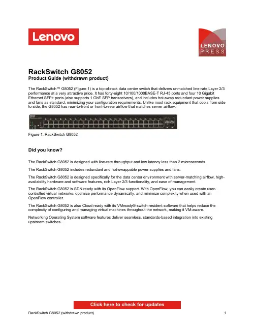
RackSwitch G8052Product Guide (withdrawn product)The RackSwitch™ G8052 (Figure 1) is a top-of-rack data center switch that delivers unmatched line-rate Layer 2/3 performance at a very attractive price. It has forty-eight 10/100/1000BASE-T RJ-45 ports and four 10 Gigabit Ethernet SFP+ ports (also supports 1 GbE SFP transceivers), and includes hot-swap redundant power supplies and fans as standard, minimizing your configuration requirements. Unlike most rack equipment that cools from side to side, the G8052 has rear-to-front or front-to-rear airflow that matches server airflow.Figure 1. RackSwitch G8052Did you know?The RackSwitch G8052 is designed with line-rate throughput and low latency less than 2 microseconds.The RackSwitch G8052 includes redundant and hot-swappable power supplies and fans.The RackSwitch G8052 is designed specifically for the data center environment with server-matching airflow, high-availability hardware and software features, rich Layer 2/3 functionality, and ease of management.The RackSwitch G8052 is SDN ready with its OpenFlow support. With OpenFlow, you can easily create user-controlled virtual networks, optimize performance dynamically, and minimize complexity when used with an OpenFlow controller.The RackSwitch G8052 is also Cloud ready with its VMready® switch-resident software that helps reduce the complexity of configuring and managing virtual machines throughout the network, making it VM-aware. Networking Operating System software features deliver seamless, standards-based integration into existing upstream switches.Click here to check for updatesDescription Partnumber Feature code(MTM 7309-HC1 / 7309-HC2)MaximumquantitysupportedSFP transceivers - 1 GbELenovo 1000BASE-T SFP Transceiver (does not support 10/100 Mbps)00FE333A5DL4 Lenovo 1000BASE-SX SFP Transceiver81Y162232694 Lenovo 1000BASE-LX SFP Transceiver90Y9424A1PN4 SFP+ transceivers - 10 GbELenovo 10GBASE-SR SFP+ Transceiver46C344750534 Lenovo 10GBASE-LR SFP+ Transceiver90Y9412A1PM4 Lenovo 10GBASE-ER SFP+ Transceiver90Y9415A1PP4 Optical cables for 1 GbE SFP SX and 10 GbE SFP+ SR transceiversLenovo 0.5m LC-LC OM3 MMF Cable00MN499ASR54 Lenovo 1m LC-LC OM3 MMF Cable00MN502ASR64 Lenovo 3m LC-LC OM3 MMF Cable00MN505ASR74 Lenovo 5m LC-LC OM3 MMF Cable00MN508ASR84 Lenovo 10m LC-LC OM3 MMF Cable00MN511ASR94 Lenovo 15m LC-LC OM3 MMF Cable00MN514ASRA4 Lenovo 25m LC-LC OM3 MMF Cable00MN517ASRB4 Lenovo 30m LC-LC OM3 MMF Cable00MN520ASRC4 SFP+ passive direct-attach cables - 10 GbELenovo 0.5m Passive SFP+ DAC Cable00D6288A3RG4 Lenovo 1m Passive SFP+ DAC Cable90Y9427A1PH4 Lenovo 1.5m Passive SFP+ DAC Cable00AY764A51N4 Lenovo 2m Passive SFP+ DAC Cable00AY765A51P4 Lenovo 3m Passive SFP+ DAC Cable90Y9430A1PJ4 Lenovo 5m Passive SFP+ DAC Cable90Y9433A1PK4 Lenovo 7m Passive SFP+ DAC Cable00D6151A3RH4 SFP+ active direct-attach cables - 10 GbELenovo 1m Active SFP+ DAC Cable95Y0323A25A4 Lenovo 3m Active SFP+ DAC Cable95Y0326A25B4 Lenovo 5m Active SFP+ DAC Cable95Y0329A25C4 Lenovo 1m Active DAC SFP+ Cable (replaces 95Y0323)00VX111AT2R4 Lenovo 3m Active DAC SFP+ Cable (replaces 95Y0326)00VX114AT2S4 Lenovo 5m Active DAC SFP+ Cable (replaces 95Y0329)00VX117AT2T4BenefitsFigure 2. Front panel of the RackSwitch G8052 Figure 3. Rear panel of the RackSwitch G8052Figure 4. Rack-optimized server aggregation 1GbE attached rack serversFigure 5. Rack-optimized server aggregation logical designFigure 6. NAS and iSCSI storage connectivityTrademarksLenovo and the Lenovo logo are trademarks or registered trademarks of Lenovo in the United States, other countries, or both. A current list of Lenovo trademarks is available on the Web athttps:///us/en/legal/copytrade/.The following terms are trademarks of Lenovo in the United States, other countries, or both:Lenovo®BladeCenter®Flex SystemIntelligent ClusterLenovoEMCNeXtScaleNeXtScale System®RackSwitchSystem x®ThinkServer®VMready®iDataPlex®The following terms are trademarks of other companies:Microsoft® is a trademark of Microsoft Corporation in the United States, other countries, or both.Other company, product, or service names may be trademarks or service marks of others.。
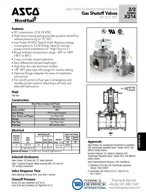
Features• DC construction (12 & 24 VDC)• High-force closing spring provides positive shutoff for reverse pressure up to 15" W.C.• Low Power 24 VDC Peak & Hold: Reduces energy consumption to 3.2 W (Hold). Ideal for remote power-critical installations (2" High Flow to 3")• Broad ambient temperature range: -40˚F to 140˚F (-40˚C to 60˚C)•2-way normally closed operation •Zero differential piloted diaphragm •High-flow die-cast aluminum bodies•1/8" NPT pipe taps with plugs for routine testing • Optional flange adapters for ease of installation and service•For on/off control of fuel gas in emergency and standby power systems requiring a primary and alternate fuel source319^ &Solenoid EnclosuresOpen Frame: 18" leads std; 72" leads optionalType 1 General Purpose: Metal housing with 7/8" hole for 1/2" conduit connectionValve Response TimeValve Opening / Closing Time: Less than 1 secondCloseoff Pressure50 psi (3.5 bar) maximum (3/4" to 2")5 psi (0.35 bar) maximum (2" High Flow to 3")FluidFuel GasGeneral Purpose: UL Listed to standard 429"Electrically Operated Valve", Guide YIOZ, File MP618Safety ValvesOpen Frame/General Purpose: CSA Certified to:1) Standard C22.2 No.139 "Electrically Operated Valves", File 0103812) Automatic Gas Valves Z21.21, CSA 6.5 C/I, File 112872320How to Order (Example: X214439998001H3)H3 12VDC / H H1 24VDC / H H3 12VDC / H H1 24VDC / H 001* 3/4"002* 1"003* 1-1/4"004* 1-1/2"005* 1-1/4", High flow 006* 1-1/2", High flow 007* 2"018 2", High flow 019 2-1/2"010 3"X214439998 Small body, Open frame* 18" leads std. For 72” Leads change 1st digit to 1 (example, 101)X214440000 Large body, Type 1 General Purpose EnclosureX214439999 Medium body Open frameF1 24VDC / FC O M B U S T I O N321Dimensions inches (mm)Dimensions inches (mm)COMBUSTION322。
Lenovo Flex System Fabric EN4093R 10Gb Scalable SwitchProduct GuideThe Lenovo® Flex System Fabric EN4093R 10Gb Scalable Switch provides unmatched scalability, port flexibility, and performance. The switch also delivers innovations to help address several networking concerns today and provides capabilities that help you prepare for the future.This switch can support up to 64x 10 Gb Ethernet connections while offering Layer 2/3 switching, in addition to OpenFlow and "easy connect" modes. It installs within the I/O module bays of the Flex System™ Enterprise Chassis. This switch can help clients migrate to a 10 Gb or 40 Gb Ethernet infrastructure, offers cloud-ready virtualization features (such as Virtual Fabric and VMready®), and is Software Defined Network (SDN) ready. The EN4093R 10Gb Scalable Switch is shown in the following figure.Figure 1. Lenovo Flex System Fabric EN4093R 10Gb Scalable SwitchDid you know?The base switch configuration comes standard with 24x 10 GbE port licenses that can be assigned to internal connections or external SFP+ or QSFP+ ports with flexible port mapping. For example, this feature allows you to trade off four 10 GbE ports for one 40 GbE port (or vice versa) or trade off one external 10 GbE SFP+ port for one internal 10 GbE port (or vice versa). You then have the flexibility of turning on more ports when you need them by using Lenovo's Features on Demand upgrade licensing capabilities that provide “pay as you grow” scalability without the need to buy more hardware.The EN4093R is cloud ready with support for VM aware networking and advanced NIC virtualization technologies, such as Unified Fabric Port (UFP). In addition, the switch offers different operational modes (from "easy connect" transparent networking connectivity to Layer 3 functionality) to satisfy diverse client networking requirements.The EN4093R switch is SDN-ready with support for OpenFlow. OpenFlow is the protocol that enables the network administrator to easily configure and manage virtual networks that control traffic on a "per-flow" basis. OpenFlow creates multiple independent virtual networks and related policies without dealing with the complexities of the underlying physical network and protocols.With support for Converged Enhanced Ethernet (CEE), the EN4093R can be used as an FCoE transit device and is ideal for network-attached storage (NAS) and iSCSI environments.Click here to check for updatesFigure 2. Front panel of the Flex System Fabric EN4093R 10Gb Scalable SwitchThe front panel includes the following components:System LEDs that display the status of the switch module and the network.One mini-USB RS-232 console port that provides another means to configure the switch module.14x SFP/SFP+ ports to attach SFP/SFP+ transceivers for 1 GbE or 10 GbE connections or SFP+ DAC cables for 10 GbE connections.2x QSFP+ ports to attach QSFP+ transceivers or DAC cables for 40 GbE or 4x 10 GbE connections.1x RJ-45 10/100/1000 Mb Ethernet port for out-of-band management.The supported transceivers and cables are listed in the following table. Table 5. Supported transceivers and direct-attach cablesDescription Part number FeaturecodeMaximumquantitysupportedSerial console cablesFlex System Management Serial Access Cable Kit90Y9338A2RR1 SFP transceivers - 1 GbELenovo 1000BASE-T (RJ-45) SFP Transceiver (no 10/100 Mbps support)00FE333A5DL14 Lenovo 1000BASE-SX SFP Transceiver81Y1622326914 Lenovo 1000BASE-LX SFP Transceiver90Y9424A1PN14 SFP+ transceivers - 10 GbELenovo Dual Rate 1/10Gb SX/SR SFP+ Transceiver00MY034ATTJ14 Lenovo 10Gb SFP+ SR Transceiver (10GBASE-SR)46C3447505314 Lenovo 10GBASE-LR SFP+ Transceiver00FE331B0RJ14 Lenovo 10GBASE-T SFP+ Transceiver7G17A03130AVV114 Optical cables for 1 GbE SX SFP, 10 GbE SR SFP+, and 40 GbE SR QSFP+ BiDi transceiversLenovo 1m LC-LC OM3 MMF Cable00MN502ASR614 Lenovo 3m LC-LC OM3 MMF Cable00MN505ASR714 Lenovo 5m LC-LC OM3 MMF Cable00MN508ASR814 Lenovo 10m LC-LC OM3 MMF Cable00MN511ASR914 Lenovo 15m LC-LC OM3 MMF Cable00MN514ASRA14 Lenovo 25m LC-LC OM3 MMF Cable00MN517ASRB14 Lenovo 30m LC-LC OM3 MMF Cable00MN520ASRC14 SFP+ active optical cables - 10 GbELenovo 1m SFP+ to SFP+ Active Optical Cable00YL634ATYX14 Lenovo 3m SFP+ to SFP+ Active Optical Cable00YL637ATYY14 Lenovo 5m SFP+ to SFP+ Active Optical Cable00YL640ATYZ14 Lenovo 7m SFP+ to SFP+ Active Optical Cable00YL643ATZ014 Lenovo 15m SFP+ to SFP+ Active Optical Cable00YL646ATZ114 Lenovo 20m SFP+ to SFP+ Active Optical Cable00YL649ATZ214 SFP+ direct-attach cables - 10 GbELenovo 1m Passive SFP+ DAC Cable90Y9427A1PH14 Lenovo 1.5m Passive SFP+ DAC Cable00AY764A51N14 Lenovo 2m Passive SFP+ DAC Cable00AY765A51P14 Lenovo 3m Passive SFP+ DAC Cable90Y9430A1PJ14 Lenovo 5m Passive SFP+ DAC Cable90Y9433A1PK14 Lenovo 7m Passive SFP+ DAC Cable00D6151A3RH14 QSFP+ transceivers - 40 GbELenovo 40GBase QSFP+ Bi-Directional Transceiver00YL631ATYW2 Lenovo 40GBASE-SR4 QSFP+ Transceiver49Y7884A1DR2 Lenovo 40GBASE-iSR4 QSFP+ Transceiver00D9865ASTM2 Lenovo 40GBASE-eSR4 QSFP+ Transceiver00FE325A5U92 Lenovo 40GBASE-LR4 QSFP+ Transceiver00D6222A3NY2Optical cables for 40 GbE QSFP+ SR4/iSR4/eSR4 transceivers Lenovo 10m QSFP+ MPO-MPO OM3 MMF Cable 00VX003AT2U 2Lenovo 30m QSFP+ MPO-MPO OM3 MMF Cable00VX005AT2V 2Optical breakout cables for 40 GbE QSFP+ iSR4/eSR4 transceivers Lenovo 1m MPO-4xLC OM3 MMF Breakout Cable 00FM412A5UA 2Lenovo 3m MPO-4xLC OM3 MMF Breakout Cable 00FM413A5UB 2Lenovo 5m MPO-4xLC OM3 MMF Breakout Cable 00FM414A5UC2QSFP+ active optical cables - 40 GbELenovo 1m QSFP+ to QSFP+ Active Optical Cable 7Z57A04256AX422Lenovo 3m QSFP+ to QSFP+ Active Optical Cable 00YL652ATZ32Lenovo 5m QSFP+ to QSFP+ Active Optical Cable 00YL655ATZ42Lenovo 7m QSFP+ to QSFP+ Active Optical Cable 00YL658ATZ52Lenovo 15m QSFP+ to QSFP+ Active Optical Cable 00YL661ATZ62Lenovo 20m QSFP+ to QSFP+ Active Optical Cable 00YL664ATZ72QSFP+ active optical breakout cables - 40 GbE to 4x10 GbE Lenovo 1M QSFP+ to 4xSFP+ Active Optical Cable 00YL667ATZ82Lenovo 3M QSFP+ to 4xSFP+ Active Optical Cable 00YL670ATZ92Lenovo 5M QSFP+ to 4xSFP+ Active Optical Cable 00YL673ATZA 2QSFP+ direct-attach cables - 40 GbE Lenovo 1m Passive QSFP+ DAC Cable 49Y7890A1DP 2Lenovo 3m Passive QSFP+ DAC Cable 49Y7891A1DQ 2Lenovo 5m Passive QSFP+ DAC Cable 00D5810A2X82Lenovo 7m Passive QSFP+ DAC Cable 00D5813A2X92QSFP+ breakout cables - 40 GbE to 4x10 GbELenovo 1m Passive QSFP+ to SFP+ Breakout DAC Cable 49Y7886A1DL 2Lenovo 3m Passive QSFP+ to SFP+ Breakout DAC Cable 49Y7887A1DM 2Lenovo 5m Passive QSFP+ to SFP+ Breakout DAC Cable49Y7888A1DN2DescriptionPart number Featurecode Maximum quantity supportedThe network cables that can be used with the switch are listed in the following table.Table 6. EN4093R network cabling requirementsTransceiver Standard Cable Connector 40 Gb Ethernet40Gb SR QSFP+ BiDi (00YL631)40GBASE-SRBiDiUp to 30 m with fiber optic cables supplied by Lenovo (seeTable 5); up to 100 m with OM3 or up to 150 m with OM4multimode fiber optic cable.LC40Gb SR4 QSFP+ (49Y7884)40GBASE-SR410 m or 30 m MPO fiber optic cables supplied byLenovo (see Table 5); up to 100 m with OM3 or up to 150 mwith OM4 multimode fiber optic cable.MPO40Gb iSR4 QSFP+ (00D9865)40GBASE-SR410 m or 30 m MPO fiber optic cables or MPO-4xLCbreakout cables up to 5 m supplied by Lenovo (see Table5); up to 100 m with OM3 or up to 150 m with OM4multimode fiber optic cable.MPO40Gb eSR4 QSFP+ (00FE325)40GBASE-SR410 m or 30 m MPO fiber optic cables or MPO-4xLCbreakout cables up to 5 m supplied by Lenovo (see Table5); up to 300 m with OM3 or up to 400 m with OM4multimode fiber optic cable.MPO40Gb LR4 QSFP+(00D6222)40GBASE-LR41310 nm single-mode fiber optic cable up to 10 km.LCActive optical cable40GBASE-SR4QSFP+ to QSFP+ active optical cables up to 1 m; QSFP+to 4x SFP+ active optical break-out cables up to 5 m for 4x10 GbE SFP+ connections out of a 40 GbE port (see Table5)QSFP+Direct attach copper cable40GBASE-CR4QSFP+ to QSFP+ DAC cables up to 7 m; QSFP+ to4x SFP+ DAC break-out cables up to 5 m for 4x 10 GbESFP+ connections out of a 40 GbE port (see Table 5).QSFP+ 10 Gb Ethernet10Gb SR SFP+ (46C3447) 1/10Gb SFP+ (00MY034)10GBASE-SR Up to 30 m with fiber optic cables supplied by Lenovo (seeTable 5); up to 300 m with OM3 or up to 400 m with OM4multimode fiber optic cable.LC10Gb LR SFP+ (00FE331)10GBASE-LR1310 nm single-mode fiber optic cable up to 10 km.LC 10Gb RJ-45 SFP+(7G17A03130)10GBASE-T UTP Category 6a or 7 up to 30 meters.RJ-45 Active optical cable10GBASE-SR SFP+ active optical cables up to 20 m (see Table 5)SFP+ Direct attach copper cable10GSFP+Cu SFP+ DAC cables up to 7 m (see Table 5).SFP+ 1 Gb Ethernet1Gb RJ-45 SFP (00FE333)1000BASE-T UTP Category 5, 5E, or 6 up to 100 meters.RJ-451Gb SX SFP (81Y1622) 1/10Gb SFP+ (00MY034)1000BASE-SX Up to 30 m with fiber optic cables supplied by Lenovo (seeTable 5); 850 nm multimode fiber cable 50 µ (OM2) up to550 m or 62.5 µ (OM1) up to 220 m.LC1Gb LX SFP (90Y9424)1000BASE-LX1310 nm single-mode fiber optic cable up to 10 km.LC Management ports1 GbE management port1000BASE-T UTP Category 5, 5E, or 6 up to 100 meters.RJ-45 RS-232 management port RS-232DB-9-to-mini-USB or RJ-45-to-mini-USB console cable(comes with the optional Cable Kit, 90Y9338).Mini-USBFigure 3. Location of the I/O bays in the Flex System Enterprise ChassisThe EN4093R switches can be installed in bays 1, 2, 3, and 4 of the Enterprise chassis. A supported adapter must be installed in the corresponding slot of the compute node. Each adapter can use up to four lanes to connect to the respective I/O module bay. The EN4093R can use up to three of the four lanes.In compute nodes that have an integrated dual-port 10 GbE network interface controller (NIC), NIC ports are routed to bays 1 and 2 with a specialized periscope connector, and the adapter is not required. However, the periscope connector can be replaced with the adapter when needed. In such a case, integrated NIC is disabled. With flexible port mapping, there is no need to buy switch upgrades for 4-port and 8-port adapters if the total number of port licenses on the switch does not exceed the number of external (upstream network ports) and internal (compute node network ports) connections that are used.The following table shows compatibility information for the EN4093R and Flex System chassis.Table 7. Flex System chassis compatibilityThe midplane connections between the adapters that are installed in the compute nodes to the I/O module bays in the chassis are listed in the following table. Half-wide compute nodes support up to two adapters, and full-wide compute nodes support up to four adapters.Table 8. Adapter to I/O bay correspondenceI/O adapter slotin the compute node Port on the adapter Corresponding I/O module bay in the chassisBay 1Bay 2Bay 3Bay 4Slot 1Port 1YesPort 2YesPort 3YesPort 4YesPort 5YesPort 6YesPort 7*Port 8*Slot 2Port 1YesPort 2YesPort 3YesPort 4YesPort 5YesPort 6YesPort 7*Port 8*Slot 3(full-wide compute nodes only)Port 1YesPort 2Yes Port 3YesPort 4Yes Port 5YesPort 6Yes Port 7*Port 8*Slot 4(full-wide compute nodes only)Port 1YesPort 2Yes Port 3YesPort 4Yes Port 5YesPort 6Yes Port 7*Port 8** Ports 7 and 8 are routed to I/O bays 1 and 2 (Slot 1 and Slot 3) or 3 and 4 (Slot 2 and Slot 4), but these ports cannot be used with the EN4093R switch.The following table lists the adapters that are supported by the I/O module.Table 9. Network adaptersDescription Part number Featurecode50 Gb EthernetThinkSystem QLogic QL45212 Flex 50Gb 2-Port Ethernet Adapter7XC7A05843B2VT ThinkSystem QLogic QL45262 Flex 50Gb 2-Port Ethernet Adapter with iSCSI/FCoE7XC7A05845B2VV25 Gb EthernetThinkSystem QLogic QL45214 Flex 25Gb 4-Port Ethernet Adapter7XC7A05844B2VU10 Gb EthernetEmbedded 10Gb Virtual Fabric Adapter (2-port)†None None Flex System CN4052S 2-port 10Gb Virtual Fabric Adapter00AG540ATBT Flex System CN4052S 2-port 10Gb Virtual Fabric Adapter Advanced01CV780AU7X Flex System CN4054S 4-port 10Gb Virtual Fabric Adapter00AG590ATBS Flex System CN4054S 4-port 10Gb Virtual Fabric Adapter Advanced01CV790AU7Y1 Gb EthernetEmbedded 1 Gb Ethernet controller (2-port)*None None† The Embedded 10Gb Virtual Fabric Adapter is built into selected compute nodes.* The Embedded 1 Gb Ethernet controller is built into selected compute nodes.Network connectivityThe following table lists the 10 Gb, 25 Gb, and 40 Gb Ethernet network switches that are offered by Lenovo that can be used with the EN4093R switch in Flex System network connectivity solutions.Table 10. Network switchesDescription Part number 10 Gb Ethernet switchesLenovo ThinkSystem NE1032 RackSwitch (Rear to Front)7159A1X Lenovo ThinkSystem NE1032T RackSwitch (Rear to Front)7159B1X Lenovo ThinkSystem NE1064TO RackSwitch (Rear to Front, ONIE)7Z330O11WW Lenovo ThinkSystem NE1072T RackSwitch (Rear to Front)7159C1X Lenovo RackSwitch G8272 (Rear to Front)7159CRW25 Gb Ethernet switchesLenovo ThinkSystem NE2572 RackSwitch (Rear to Front)7159E1X Lenovo ThinkSystem NE2572O RackSwitch (Rear to Front, ONIE)7Z210O21WW Lenovo ThinkSystem NE2580O RackSwitch (Rear to Front, ONIE)7Z330O21WW 100 Gb Ethernet switches (support 40 GbE connectivity)Lenovo ThinkSystem NE10032 RackSwitch (Rear to Front)7159D1X Lenovo ThinkSystem NE10032O RackSwitch (Rear to Front, ONIE)7Z210O11WWFor more information, see the list of Product Guides in the Top-of-rack Switches category:/servers/options/switchesStorage connectivityThe following table lists the external storage systems that are currently offered by Lenovo that can be used with the EN4093R switch for external NAS or iSCSI SAN storage connectivity.Table 11. External storage systems: DE SeriesDescription Part number Worldwide JapanLenovo ThinkSystem DE2000HLenovo ThinkSystem DE2000H 10GBASE-T Hybrid Flash Array LFF (16 GB cache)7Y70A003WW7Y701001JP Lenovo ThinkSystem DE2000H 10GBASE-T Hybrid Flash Array SFF (16 GB cache)7Y71A002WW7Y711005JP Lenovo ThinkSystem DE2000H iSCSI Hybrid Flash Array LFF (16 GB cache)7Y70A004WW7Y701000JP Lenovo ThinkSystem DE2000H iSCSI Hybrid Flash Array SFF (16 GB cache)7Y71A003WW7Y711006JP Lenovo ThinkSystem DE4000HLenovo ThinkSystem DE4000H iSCSI Hybrid Flash Array 4U60 (16 GB cache)7Y77A000WW7Y771002JP Lenovo ThinkSystem DE4000H iSCSI Hybrid Flash Array LFF (16 GB cache)7Y74A002WW7Y74A002JP Lenovo ThinkSystem DE4000H iSCSI Hybrid Flash Array SFF (16 GB cache)7Y75A001WW7Y75A001JP Lenovo ThinkSystem DE4000FLenovo ThinkSystem DE4000F iSCSI All Flash Array SFF (16 GB cache)7Y76A002WW7Y76A002JP Lenovo ThinkSystem DE4000F iSCSI All Flash Array SFF (64 GB cache)7Y76A007WW7Y76A00AJP Lenovo ThinkSystem DE6000HLenovo ThinkSystem DE6000H iSCSI Hybrid Flash Array 4U60 (32 GB cache)7Y80A002WW7Y801000JP Lenovo ThinkSystem DE6000H iSCSI Hybrid Flash Array SFF (32 GB cache)7Y78A002WW7Y781000JP Lenovo ThinkSystem DE6000FLenovo ThinkSystem DE6000F iSCSI All Flash Array SFF (128 GB cache)7Y79A002WW7Y79A002JPTable 12. External storage systems: DM SeriesDescription Part number Lenovo ThinkSystem DM3000HThinkSystem DM3000H Hybrid Storage Array (2U12 LFF, CTO only)7Y42CTO1WW ThinkSystem DM3000H, 48TB (12x 4TB HDDs), 10GBASE-T, ONTAP 9.5 Fundamentals7Y421003EA* ThinkSystem DM3000H, 48TB (12x 4TB HDDs), 10GBASE-T, ONTAP 9.57Y421007EA* ThinkSystem DM3000H, 48TB (12x 4TB HDDs), 16Gb FC / 10GbE SFP+, ONTAP 9.5 Fundamentals7Y421009NA* ThinkSystem DM3000H, 48TB (12x 4TB HDDs), 16Gb FC / 10GbE SFP+, ONTAP 9.5 Fundamentals7Y421002EA* ThinkSystem DM3000H, 48TB (12x 4TB HDDs), 16Gb FC / 10GbE SFP+, ONTAP 9.57Y421006EA* ThinkSystem DM3000H, 96TB (12x 8TB HDDs), 10GBASE-T, ONTAP 9.5 Fundamentals7Y421005EA* ThinkSystem DM3000H, 96TB (12x 8TB HDDs), 10GBASE-T, ONTAP 9.57Y421001EA* ThinkSystem DM3000H, 96TB (12x 8TB HDDs), 16Gb FC / 10GbE SFP+, ONTAP 9.5 Fundamentals7Y421004EA* ThinkSystem DM3000H, 96TB (12x 8TB HDDs), 16Gb FC / 10GbE SFP+, ONTAP 9.57Y421008EA* Lenovo ThinkSystem DM5000HThinkSystem DM5000H Hybrid Storage Array (2U24 SFF, CTO only)7Y57CTO1WW ThinkSystem DM5000H, 11.5TB (12x 960GB SSDs), 10GBASE-T, ONTAP 9.5 Fundamentals7Y571004EA* ThinkSystem DM5000H, 11.5TB (12x 960GB SSDs), 10GBASE-T, ONTAP 9.57Y57100LEA* ThinkSystem DM5000H, 11.5TB (12x 960GB SSDs), 16Gb FC / 10GbE SFP+, ONTAP 9.5 Fundamentals7Y571011NA* ThinkSystem DM5000H, 11.5TB (12x 960GB SSDs), 16Gb FC / 10GbE SFP+, ONTAP 9.5 Fundamentals7Y571003EA*Description Part number ThinkSystem DM5000H, 11.5TB (12x 960GB SSDs), 16Gb FC / 10GbE SFP+, ONTAP 9.57Y57100KEA* ThinkSystem DM5000H, 14.4TB (12x 1.2TB HDDs), 10GBASE-T, ONTAP 9.5 Fundamentals7Y57100CEA*7Y57100BEA* ThinkSystem DM5000H, 14.4TB (12x 1.2TB HDDs), 16Gb FC / 10GbE SFP+, ONTAP 9.5FundamentalsThinkSystem DM5000H, 21.6TB (12x 1.8TB HDDs), 10GBASE-T, ONTAP 9.5 Fundamentals7Y57100GEA* ThinkSystem DM5000H, 21.6TB (12x 1.8TB HDDs), 16Gb FC / 10GbE SFP+, ONTAP 9.57Y57100FEA* FundamentalsThinkSystem DM5000H, 23TB (24x 960GB SSDs), 10GBASE-T, ONTAP 9.5 Fundamentals7Y571006EA* ThinkSystem DM5000H, 23TB (24x 960GB SSDs), 10GBASE-T, ONTAP 9.57Y57100NEA* ThinkSystem DM5000H, 23TB (24x 960GB SSDs), 16Gb FC / 10GbE SFP+, ONTAP 9.5 Fundamentals7Y571005EA* ThinkSystem DM5000H, 23TB (24x 960GB SSDs), 16Gb FC / 10GbE SFP+, ONTAP 9.57Y57100MEA* ThinkSystem DM5000H, 28.8TB (24x 1.2TB HDDs), 10GBASE-T, ONTAP 9.5 Fundamentals7Y57100EEA* ThinkSystem DM5000H, 28.8TB (24x 1.2TB HDDs), 10GBASE-T, ONTAP 9.57Y57100VEA*7Y57100DEA* ThinkSystem DM5000H, 28.8TB (24x 1.2TB HDDs), 16Gb FC / 10GbE SFP+, ONTAP 9.5FundamentalsThinkSystem DM5000H, 43.2TB (24x 1.8TB HDDs), 10GBASE-T, ONTAP 9.5 Fundamentals7Y57100JEA* ThinkSystem DM5000H, 43.2TB (24x 1.8TB HDDs), 10GBASE-T, ONTAP 9.57Y571002EA*7Y571010NA* ThinkSystem DM5000H, 43.2TB (24x 1.8TB HDDs), 16Gb FC / 10GbE SFP+, ONTAP 9.5Fundamentals7Y57100HEA* ThinkSystem DM5000H, 43.2TB (24x 1.8TB HDDs), 16Gb FC / 10GbE SFP+, ONTAP 9.5FundamentalsThinkSystem DM5000H, 43.2TB (24x 1.8TB HDDs), 16Gb FC / 10GbE SFP+, ONTAP 9.57Y57100ZEA* ThinkSystem DM5000H, 46TB (12x 3.84TB SSDs), 10GBASE-T, ONTAP 9.5 Fundamentals7Y571008EA* ThinkSystem DM5000H, 46TB (12x 3.84TB SSDs), 10GBASE-T, ONTAP 9.57Y57100QEA* ThinkSystem DM5000H, 46TB (12x 3.84TB SSDs), 16Gb FC / 10GbE SFP+, ONTAP 9.5 Fundamentals7Y571007EA* ThinkSystem DM5000H, 46TB (12x 3.84TB SSDs), 16Gb FC / 10GbE SFP+, ONTAP 9.57Y57100PEA* ThinkSystem DM5000H, 92TB (24x 3.84TB SSDs), 10GBASE-T, ONTAP 9.5 Fundamentals7Y57100AEA* ThinkSystem DM5000H, 92TB (24x 3.84TB SSDs), 10GBASE-T, ONTAP 9.57Y57100REA* ThinkSystem DM5000H, 92TB (24x 3.84TB SSDs), 16Gb FC / 10GbE SFP+, ONTAP 9.5 Fundamentals7Y571009EA* ThinkSystem DM5000H, 92TB (24x 3.84TB SSDs), 16Gb FC / 10GbE SFP+, ONTAP 9.57Y57100SEA* Lenovo ThinkSystem DM5000FThinkSystem DM5000F Flash Storage Array (2U24 SFF, CTO only)7Y41CTO1WW ThinkSystem DM5000F, 11.5TB (12x 960GB SSDs), 10GBASE-T, ONTAP 9.57Y411002EA* ThinkSystem DM5000F, 11.5TB (12x 960GB SSDs), 16Gb FC / 10GbE SFP+, ONTAP 9.57Y411001EA* ThinkSystem DM5000F, 23TB (24x 960GB SSDs), 10GBASE-T, ONTAP 9.57Y411004EA* ThinkSystem DM5000F, 23TB (24x 960GB SSDs), 16Gb FC / 10GbE SFP+, ONTAP 9.57Y411003EA* ThinkSystem DM5000F, 46TB (12x 3.84TB SSDs), 10GBASE-T, ONTAP 9.57Y411006EA* ThinkSystem DM5000F, 46TB (12x 3.84TB SSDs), 16Gb FC / 10GbE SFP+, ONTAP 9.57Y411005EA* ThinkSystem DM5000F, 92TB (24x 3.84TB SSDs), 10GBASE-T, ONTAP 9.57Y411007EA* ThinkSystem DM5000F, 92TB (24x 3.84TB SSDs), 16Gb FC / 10GbE SFP+, ONTAP 9.57Y411000EA* Lenovo ThinkSystem DM7000HThinkSystem DM7000H Hybrid Storage Array (3U, CTO only)7Y56CTO1WW Lenovo ThinkSystem DM7000FThinkSystem DM7000F Flash Storage Array (3U, CTO only)7Y40CTO1WW * Preconfigured models that are available only in North America (part numbers that have NA at the end) or EMEA (part numbers thatTrademarksLenovo and the Lenovo logo are trademarks or registered trademarks of Lenovo in the United States, other countries, or both. A current list of Lenovo trademarks is available on the Web athttps:///us/en/legal/copytrade/.The following terms are trademarks of Lenovo in the United States, other countries, or both:Lenovo®Flex SystemNMotion®RackSwitchThinkSystem®VMready®XClarity®The following terms are trademarks of other companies:Intel® is a trademark of Intel Corporation or its subsidiaries.Hyper-V® and Microsoft® are trademarks of Microsoft Corporation in the United States, other countries, or both. Other company, product, or service names may be trademarks or service marks of others.。

Dual-Band11ac High SpeedModern homes and businesses need high-performance, reliable and secure Wi-Fi. The BR-6478AC V2 dual-band 802.11ac router features the latest 11ac standard for faster, better Wi-Fi and built-in VPN support to make VPN access easy across all of your devices. Easy, secure access to remote networks from anywhere as well as privacy, security and freedom from regional restrictions online. The improved V2 design also features a new USB port for file & printer-sharing across your network. Attach a USB hard-drive for central NAS (Network Attached Storage) access on any device in your network and stream content at lightning, lag-free 11ac speeds.AC1200 Gigabit Dual-Band Wi-Fi Routerwith USB Port & VPNBR-6478AC V2Next-Generation Wireless NetworkingThe Edimax BR-6478AC V2 router supports the next generation IEEE 802.11ac wireless standard, meaning higher data rates in the 5GHz band. With 300Mbps speeds in the 2.4GHz band and 867Mbps speeds in 5GHz, the BR-6478AC V2 is ideal for HD video streaming and large file transfers. The router is also backward compatible with 802.11a/b/g/n to ensure compatibility with legacy Wi-Fi devices.Concurrent Dual-Band Wi-Fi ConnectivityThe Edimax BR-6478AC V2 router provides simultaneous 2.4GHz (802.11n) and 5GHz (802.11ac) wireless network connectivity for maximum flexibility of use.5GHz (Up to 867Mbps) Interference-Free HD Video and Gaming2.4GHz (Up to 300Mbps)More Supported Devices Basic Internet ApplicationsOnline Gaming HD Video StreamingVoIP CallingWeb Browsing Online ChatEmail and DownloadingAC1200: 867Mbps(5GHz) + 300Mbps(2.4GHz)Secure Private NetworkSmart Setup, No CD RequiredConcurrent Dual-BandMulti-Function USB PortMaximum Speed: Next Generation 802.11ac vs. 802.11n3Xof 11n 300Mbps(Theoretical throughput)Gigabit1000 Mbps10X Faster100Mbps1000MbpsBR-6478AC V2Multi-Function USB PortConnect a USB hard-drive and enjoy your own private cloud storage. Keep content on your central storage and access it from any device on your network, such as movie and TV streaming to PCs or smart TVs, or for regular backups of vital data. With the built-in VPN function you can even access your network remotely when you’re away from home. It can also be used with an FTP server or printer, so any devices on your network can print over your Wi-Fi.AC1200 Gigabit Dual-Band Wi-Fi Routerwith USB Port & VPNVPN Access for Privacy & SecurityBuilt-in Virtual Private Network (VPN) support for easy VPN access on all your devices. VPNs enable you to access secure, remote networks from anywhere and can offer privacy and security online. Log in to your work/school networkremotely or avoid geoblocking, protect privacy on public Wi-Fi and bypass Internet censorship.Home Users: Avoid regional restrictions and access geoblocked content such as Netflix or iPlayer from anywhere. Ensure your privacy and anonymity online and defeat censorship and other location-based content restrictions. You can also remotely access your home network when you’re away, and use your encrypted VPN for security when out and about using potentially unsafe public Wi-Fi hotspots.Small Office Users: Enable your employees to access company resources remotely such as email, documents saved on the company server and any programs/systems when they are outside the office.Small Office UserRemote NetworkHotel & Remote StaffHomeBranch OfficeInternetOffice VPN RouterOffice/HQEmail, Programs & SystemServersHome UserRestricted NetworkOffice/SchoolHotspotCountryInternetHome/Remote SiteVPN RouterFree From RestrictionsNetwork Attached Storage (NAS)FTP Server USB PortPrinter StorageSmart iQ SetupFeatures iQ Setup for smart, automatic and quick installation with no CD required, no smartphone app downloaded, and no PC required.BR-6478AC V2High Gain Antennas For Better Wi-Fi Performance Employing two external high-gain fixed antennas, the BR-6478AC V2 provides powerful 2.4GHz and 5GHz dual-band signal strength and enhances Wi-Fi range, providing signal penetration through walls and floors across your home or office.2.4GHz/5GHz Wi-Fi5-in-1 Router, Access Point, Range Extender , Wireless Bridge and WISPThe BR-6478AC V2 can work as router, access point, range extender, wireless bridge or WISP. Just configure the mode you need for your network environment using the smart iQ Setup wizard.with USB Port & VPNHigh Gain AntennasSwitch mode using the smart iQ setup wizard on any device with a web browser, no CD required.*Mobile device setup requires iOS 4.0 or Android 4.0 and above.Easy 3-Step Smart iQ SetupJust plug in the cablesOpen the browser to access iQ Setup page*Enjoy surfing the web*iQ Setup will guide you through setupSwitch mode with one click!BR-6478AC V2Edimax’s Revolutionary iQoSiQoS is Edimax’s solution for a quicker, easier, and more effective way to manage Internet bandwidth. While Quality of Service (QoS) functionality is a common feature in routers across the market, typically only advanced users have the knowledge required to set up the complex parameters. Edimax though has redesigned QoS with user-friendliness and accessibility in mind. A simple and intuitive user interface allows users to arrange bandwidth priority settings in just a few clicks. With iQoS, you can enjoy gaming, video streaming, VoIPapplications and BT clients at the same time without the usual nightmare of lag and interruptions. An original, efficient and effective means of managing your Internet bandwidth.Guest Network*Supports a guest network to provide connectivity while isolating guests from your primary network. *Router mode onlyMulti-SSID & VLAN Support*Multi-SSID enables users to configure up to ten separate SSIDs (2.4GHz x 5 and 5GHz x 5) in order to group and manage users according to your requirements. Inaddition, each SSID can be assigned a different VLAN ID, so users with multiple VLANs can manage the network access level of each SSID – ensuring security and protecting confidential or critical network resources. *Access point mode onlywith USB Port & VPNMainPrivate & Secure Wi-FiGuest Wi-FiInternetRouterSSID 1 Parents SSID 2 ChildrenSSID 4 Guest SSID 3 Home MediaNo QoSEdimax iQoSHigh Priority Low PriorityMedia Gaming DataHARDWARE INTERFACEBR-6478AC V2Power PortReset/WPS ButtonHigh GainAntennas2.4GHz/5GHz 2.4GHz/5GHzUSB Port10/100/1000MbpsGigabit LAN Ports10/100/1000MbpsGigabit WAN Portwith USB Port & VPNFEATURES & TECHNICAL SPECIFICATIONSFUNCTIONS HARDWARE INTERFACE MANAGEMENT & INSTALLATIONSupports Wi-Fi router, access point,Wi-Fi extender, Wi-Fi bridge andWISP modesSupports OpenVPN Server for private network with high security & flexible DNS proxy for filtering and monitoring illegal DNS trafficGuest networkUp to 10 SSIDs (2.4GHz x 5 and 5GHz x 5) with VLAN support in AP modeIGMP proxy and IGMP snoopingDDNS and DHCPPort triggering for special applications Virtual server and DMZ hostingMAC/IP filter and HTTP blockingiQoS for smart bandwidthmanagementStatic routingUPnP architectureWi-Fi schedule control1 x RJ-45 10/100/1000M WAN port4 x RJ-45 10/100/1000M LAN portLED indicators: Power, Internet,WLAN, USB2 x Dual-band antennasWPS/Reset button1 x USB 2.0 portMulti-language user interfaceSupports remote managementSystem status and security logFault tolerance firmware upgradeAuto firmware upgradeAuto restart while malfunction(Watch Dog)Smart iQ Setup, no CD requiredSupports smartphone, tablet orlaptop setup (iOS 4 or Android 4 andabove are required for smartphone ortablet setup).WAN OUTPUT POWER & SENSITIVITYGAIN (5GHz) OUTPUT POWER & SENSITIVITY GAIN (2.4GHz)WAN protocol: PPPoE, Static IP, Dynamic IP, PPTP and L2TPSupports WISP connection mode Output Power11a(6bps): 18±1.5dBm11a(54bps): 14±1.5dBm11n(20MHz, MCS7): 13±1.5dBm11n(40MHz, MCS7): 13±1.5dBm11ac(80MHz, MCS9): 13±1.5dBmReceive Sensitivity11a(6Mbps): ‐90±2dBm11a(54Mbps): ‐71±2dBm11n(20MHz, MCS7): ‐69±2dBm11n(40MHz, MCS7): ‐65±2dBm11ac(80MHz, MCS9): -55±2dBmOutput Power11b (1Mbps): 18±1.5dBm11b (11Mbps): 16±1.5dBm11g (54Mbps): 14±1.5dBm11n (20MHz, MCS7): 13±1.5dBm11n (40MHz, MCS7): 13±1.5dBmReceive Sensitivity11b(1Mbps): ‐91±2dBm11b(11Mbps): ‐87±2dBm11g (54Mbps): ‐71±2dBm11n(20MHz, MCS7): ‐68±2dBm11n(40MHz, MCS7): ‐65±2dBmSECURITY MEMORY HUMIDITY & TEMPERATUREWEP, WPA and WPA2 security QoS for critical operationsSPI anti-DoS firewall 8MB NOR Flash64MB RAM10-90% (non-condensing)0-40o CPOWER ADAPTER DIMENSIONS & WEIGHTS CERTIFICATIONSDC 12V, 1.25A (UK, AU) DC 12V, 1.5A (US, EU) 190.2mm x 172mm x 42mm322gFCC/CEAPPLICATION DIAGRAMwith USB Port & VPNBR-6478AC V2Maximum performance, actual data rates, and coverage will vary depending on network conditions and environmental factors. Product specifications and design are subject to change without notice.Copyright © 2015 Edimax Technology Co. Ltd. All rights reserved.Wi-Fi RouterShare an Internet connection to all of your devices.InternetModemAccess PointWired and Wi-Fi access for any existing wired network.InternetModemRouter Wi-Fi ExtenderExtend existing Wi-Fi for further coverage. InternetModemRouter Wi-Fi Bridge Let wired TVs, game consoles or media players join your wireless network.InternetModemRouter WISPShare a wireless Internet connection to all of your devices.WISP。

收稿日期:2020-01-01 修回日期:2020-05-07基金项目:国家重点研发计划(2019YFB 1804300);国家自然科学基金面上项目(61971382)作者简介:耿俊杰(1987-),男,博士研究生,CCF 会员(A 7065G ),研究方向为计算机网络架构;颜金尧,教授,博导,研究方向为宽带信息网络㊂基于可编程数据平面的PFC 算法实现耿俊杰,颜金尧(中国传媒大学信息与通信工程学院,北京100024)摘 要:当前高吞吐量㊁超低延迟的高性能无损数据中心网络成为研究的热点㊂传统TCP /IP 协议是为广域网设计的,在高速网络条件下(特别是随着10Gb /s 的网络接口的普及)会存在I /O 瓶颈问题;远程直接数据存取技术RDMA(remote direct memory access)是为了解决网络传输中终端主机的数据处理延迟㊁降低CPU 负载而产生的,最早应用在高性能计算领域㊂RDMA 技术基于优先级流量控制PFC 算法实现了无损传输网络㊂首先介绍了可编程数据平面技术和高性能数据中心网络的研究现状,并基于可编程数据平面以软件定义的方式实现了PFC 算法,进而实现了可编程的无损数据中心网络,并在仿真网络环境下对实现的PFC 算法进行了性能测试㊂实验结果显示在可编程数据平面下实现的PFC 算法达到了无损传输的目标㊂同时证明了可编程数据平面技术在高性能数据中心网络的实现中可以发挥巨大作用,相对于传统的网络架构,可编程数据平面技术由于采用了软件定义的方式,因此更加灵活㊁高效㊂关键词:可编程数据平面;数据中心;无损传输;高性能网络;流量控制中图分类号:TP301.6 文献标识码:A 文章编号:1673-629X (2021)01-0116-06doi:10.3969/j.issn.1673-629X.2021.01.021Implementation of Priority Flow Control Algorithm Based onProgrammable Data PlaneGENG Jun -jie ,YAN Jin -yao(School of Information and Communication Engineering ,Communication University of China ,Beijing 100024,China )Abstract :At present ,the lossless data center network with high throughput ,ultra -low delay and high performance has become a research hotspot.Traditional TCP /IP protocol is designed for wide area networks.TCP /IP stacks will suffer I /O bottlenecks under high -speed network conditions (especially with the popularity of 10Gb /s network interfaces ).RDMA (remote direct memory access )is developed to solve the data processing delay of the terminal host in network transmission and reduce the CPU load ,which was first applied in the field of high performance computing.RDMA realizes lossless transmission network based on PFC (priority flow control ).We first introduce the research status of programmable data plane technology and high -performance data center network and realize the PFC algorithm based on programmable data plane in the way of software definition ,and then realize the programmable lossless data center network and test the performance of the realized PFC algorithm under the simulation network environment.The experiment shows that the PFC framework realized under the programmable data plane achieves the goal of lossless transmission.At the same time ,it is proved that the programmable data plane technology can play a huge role in the realization of high -performance data center pared with the traditional network architecture ,the programmable data plane technology is more flexible and efficient since adoption of the way of software definition.Key words :programmable data plane ;data center ;lossless transmission ;high performance network ;flow control0 引 言当前互联网中存在大量的在线业务需要网络对高频率的用户请求做出快速应答,对数据中心提出了超低时延的要求;随着近年来机器学习和人工智能技术的高速发展,对于数据中心计算能力的需求大幅上升,因此数据中心部署了大量的分布式计算集群[1]以满足日益复杂的神经网络和深度学习模型,大量的分布式计算集群采用的并行程序会导致通讯延迟,进而严重影响数据中心的计算效率;同时,随着近年来数据中心流量的激增[2],数据中心往往会利用以太网融合组网的分布式存储技术来解决数据存储和读取效率问题㊂而大象流占据分布式存储网络流量的主要比例,第31卷 第1期2021年1月 计算机技术与发展COMPUTER TECHNOLOGY AND DEVELOPMENT Vol.31 No.1Jan. 2021当分布式存储网络中一旦因拥塞发生数据包丢失导致大象流重传,会严重影响数据中心效率并且会加重拥塞程度,进一步影响网络性能,因此高吞吐量㊁超低延迟的高性能无损数据中心网络成为现在研究的热点[3-5]㊂RDMA(remote direct memory access)技术[6]是目前实现超低时延㊁高吞吐量的高性能数据中心网络最常用的技术,RoCE(RDMA over converged Ethernet)协议[7]因为具备明显的性能和成本优势,目前在融合以太网数据中心中占据主流市场地位㊂而RoCEv2基于PFC(priority flow control)[8]算法实现了无损传输㊂另一方面,传统网络架构封闭㊁固化,网络协议开发部署周期长,很难适应当前对于网络创新的要求㊂在此背景下,为了应对当前网络面临的挑战,开放网络可编程能力,扩大网络创新的空间,2008年,斯坦福大学Nick McKeown教授为首的研究团队提出了OpenFlow以及软件定义网络SDN(software defined networking)技术[9-10]㊂软件定义网络技术获得了学术界和工业界的高度关注,2014年,研究者在SDN基础上又提出了可编程数据平面技术[11-12],将网络编程能力扩展到数据平面㊂在网络领域的各种创新和发展,对应对当前数据中心面临的各种问题和挑战提供了新的思路和方法㊂该文基于可编程数据平面技术实现了PFC算法,进而实现了无损数据中心网络,为实现高性能数据中心网络提供了新的思路和实现方法㊂1 可编程数据平面技术在传统网络架构中,网管系统被作为网络管理平面,而控制平面和数据平面则被分别部署在每个网络设备上㊂在这种部署方式下,网络管理十分复杂繁琐㊂另外,除了标准协议外,各个厂家都会有一些私有协议,这样就进一步加大了网络管理的复杂性㊂同时,传统网络架构下的控制平面和数据平面分布式地部署在网络中的各个设备上,并且控制平面和数据平面是固化㊁封闭的,实现网络创新需要的新功能部署周期非常长(往往是几年),显然传统网络架构已经完全不能满足当前对于网络创新的需求㊂在此背景下,软件定义网络技术以及可编程数据平面技术应运而生㊂1.1 软件定义网络技术软件定义网络技术(SDN)是斯坦福大学Nick McKeown教授团队在Clean Slate项目提出的一个概念,特别是2009年SDN南向接口协议OpenFlow1.0的发布,标志着软件定义网络技术进入高速发展的阶段㊂软件定义网络技术将网络设备控制平面和数据平面分离,通过逻辑集中的控制器实现对网络转发设备的集中管理㊂在软件定义网络架构中,控制平面具有全局化视野,通过南向接口协议实现与数据平面通信,通过开放控制平面的可编程特性,使得网络功能更加灵活和易于扩展,因此对于网络功能的部署更加灵活,同时也简化了网络的管理㊂软件定义网络技术是当前网络领域最为活跃的技术创新,被MIT评为 改变世界的十大创新技术之一”[13]㊂如图1所示,软件定义网络架构实现了控制平面和数据平面的分离,同时通过北向接口协议开放API,允许用户编程实现网络功能自定义㊂同时使用南向接口协议OpenFlow实现控制平面与数据平面的通信㊂图1 SDN网络架构1.2 可编程数据平面软件定义网络技术实现了数据平面和控制平面的分离,开放了控制平面编程能力,实现了控制平面的逻辑集中,这些特点为网络的管理和开放带来了一定的灵活性㊂但是在软件定义网络架构下,数据平面并没有被开放,其行为仍然是固定的㊂OpenFlow协议已经从2008年OpenFlow1.0版本演进到1.5版本,其中匹配域中支持的元组数量也从支持12元组增加到目前㊃711㊃ 第1期 耿俊杰等:基于可编程数据平面的PFC算法实现支持45个元组,其支持的元组数量随着OpenFlow 协议的更新也不断增加㊂但OpenFlow 协议支持的匹配域都是协议设定的,并不能支持灵活的弹性增加,对于新匹配元组的支持都需要重新编写数据平面与控制平面两端的协议栈以及数据平面的数据包处理逻辑,这种局限性导致了OpenFlow 交换机的设计难度大大增加㊂OpenFlow 协议的版本稳定性也存在很大问题,对软件定义网络技术所追求的网络创新是一种阻碍㊂Nick McKeown 教授等人提出了协议无关(programming protocol -independent packet processors )的高级编程语言P 4[11]语言,通过编写P 4代码可以自定义网络数据平面数据包的处理流程,也就是开放了数据平面的可编程能力㊂图2描述了可编程数据平面的抽象转发模型,主要由输入㊁输出端口㊁解析器㊁Ingress /Egress 控制流水线㊁队列缓存组成㊂解析器负责报文解析,当数据包进入交换机时,解析器按照解析表对进入的数据包进行报文解析,解析表是由P 4代码定义,并由编译器编译生成,通过P 4代码自定义报文头和报文头解析顺序,实现数据包的报文解析逻辑,解析器从进入交换机的数据包的报文首部解析出自定义的报文头,并赋值给P 4定义的实例化首部㊂图2 可编程数据平面抽象转发模型 匹配动作表是数据平面执行转发逻辑的基本单元,对进入交换机并匹配成功的数据包执行相应的动作,实现对数据包的处理㊂可编程数据平面的抽象转发模型实现了全流水线可编程,控制程序负责定义匹配动作表的执行顺序,进而实现转发逻辑的实现,控制流水线分为Ingress control 和Egress control 两部分㊂可编程数据平面真正实现了协议无关的数据转发,并且作为一种描述性的高级编程语言,无需关心底层设备的具体信息,实现了设备无关性和代码可移植性,使得网络更加灵活和开放㊂2 高性能数据中心网络及PFC 算法随着各种网络应用以及移动互联网的快速发展,近些年网络流量也出现了爆发式的增长㊂网络流量的激增对于作为基础设施的网络提出了更高的性能要求㊂网络中的不同应用对于网络性能的要求也不同,例如交互式应用需要网络提供更小的时延,分布式存储应用需要网络更小的丢包率,但概括来说,网络性能指标主要包括时延㊁吞吐量以及丢包率㊂因此实现超低时延㊁高吞吐量以及无丢包的高性能数据中心网络成为当前研究的热点㊂2.1 远程直接数据存取技术(RDMA )远程直接数据存取技术(RDMA )最早应用在高性能计算领域,是为了解决网络传输中服务器侧数据处理延迟㊁降低服务器CPU 负载而设计的一种技术协议㊂如图3所示,RDMA 技术通过允许用户态的应用程序直接读取和写入远程服务器端内存,避免了CPU 多次介入拷贝内存,在没有双方服务器端操作系统参与的情况下,可以绕过服务器内核,直接向网卡写数据,将数据直接从网络中一台服务器的内存传输到网络中另一台服务器㊂这样就释放了部分服务器的计算能力㊂并且,通过避免双方操作系统的介入可以消除外部存储器复制和上下文切换的开销,从而可以解放服务器内存带宽,有助于应用系统性能提升㊂RDMA 技术可以实现低时延㊁高吞吐量的高性能数据中心网络㊂目前RDMA 有三种实现方式,分别是InfiniBand ㊁iWARP (internet wide area RDMA protocol )和RoCE (RDMA over converged Ethernet )㊂(1)InfiniBand 技术[14]是由IBTA (InfiniBand tradeassociation )行业协会在1999年提出的,其标准规范在1999年开始起草并于2000年正式发表,经过不断发展,InfiniBand 架构在2005年之后开始在集群式超级计算机上广泛应用㊂InfiniBand 技术目前主要应用于高性能计算数据中心网络㊂InfiniBand 技术在RDMA 三种实现方式中㊃811㊃ 计算机技术与发展 第31卷具有最好的性能,但需要有定制的硬件设备来实现,因此也是成本最高的一种实现方案㊂图3 RDMA 模式与传统模式对比(2)iWARP 协议[15]是RDMA 技术的另外一种实现方案,是由RDMA 联盟在2002年向IETF 提出的,iWARP 协议通过在标准TCP /IP 协议栈上定义一个多层处理栈实现将RDMA 的特性集成到以太网上㊂iWARP 协议利用RDMA 技术的内核旁路㊁零内存拷贝以及避免CPU 介入等特点,有效地降低了网络延迟和服务器CPU 的负载,释放了服务器部分CPU 的计算能力㊂iWARP 协议是第一个在标准以太网基础设施上实现了RDMA 技术的方案,另外,iWARP 协议没有具体指定底层物理层设备信息,因此所有工作在使用TCP /IP 协议栈的上层协议都可以被支持,在iWARP 协议中,TCP /IP 协议栈在网卡中设计并实现㊂因此需要专有网卡来实现㊂当数据中心网络规模较大时,使用iWARP 协议会产生大量的TCP 连接,大量的TCP 连接会占用服务器大量的内存资源,进而影响系统性能,所以会带来性能和成本问题㊂(3)RoCE 技术是IBTA 提出的在融合以太网上实现RDMA 技术的一个实现方案㊂目前主流版本是RoCEv 2版本㊂RoCEv 2是基于UDP /IP 协议实现的㊂RoCEv 2由于在性能和成本上占据明显优势,因此占据了目前融合以太网数据中心市场的主流地位㊂RoCEv 2是基于不可靠传输的UDP 协议实现,与TCP 协议相比,UDP 协议更加快速㊁占用较少的计算资源,但其是不可靠传输,没有TCP 协议的滑动窗口㊁确认应答等机制,当出现丢包时会大大降低RDMA 技术的工作效率㊂图4显示了当发生丢包时RDMA 技术的吞吐率情况,可以看出丢包会严重影响RDMA 的性能㊂所以为了实现RDMA 技术的真正性能,必须实现无损传输㊂RoCEv 2协议依靠基于优先级的流量控制PFC 算法实现无损传输㊂图4 RDMA 的丢包率与吞吐率关系2.2 基于优先级的流量控制算法PFC基于优先级的流量控制算法PFC 是由电气和电子工程师协会在2008年提出的,PFC 算法通过划分虚拟实现是对传统流控协议的优化㊂当出现拥塞时,传统流控协议会将链路上的所有流量禁止发送㊂而PFC 协议通过在以太网链路上创建8个优先级通道,并实现对每个优先级通道进行暂停发送,同时不会影响其他优先级通道数据的发送㊂优先级流控PFC 的基本运行机制如下:当网络链路中发生拥塞时,即交换机的入端口队列长度超过设定的阈值时,交换机生成一个暂停帧,并将暂停帧发送给上一跳交换机,上一跳交换机接收到暂停帧后,会根据暂停帧中的信息,暂停交换机中对应优先级通道中数据的发送,暂停的时间根据暂停帧中携带的字段信息设定;同时,如果上一跳交换机中也发生了拥塞则会向其上一跳交换机发送暂停帧,如果拥塞继续则逐级暂停㊂同样的,如果交换机中拥塞消除,则向上一跳交换机发送一个暂停时间为0的暂停帧,以恢复上一跳交换机中对应优先级队列中数据的发送,以此类推,逐级发送㊂PFC 算法[16]被广泛应用于高性能数据中心网络,以确保数据中心网络的无损传输㊂图5显示了优先级流量控制PFC 的报文格式,其中DA 字段是目的MAC 地址,SA 是源MAC 地址,type 字段是报文类型,其中有关暂停优先级和暂停时间的信息包含在Parameters 字段中㊂图5 PFC 报文格式㊃911㊃ 第1期 耿俊杰等:基于可编程数据平面的PFC 算法实现3 基于可编程数据平面的PFC算法实现该文在可编程数据平面的协议无关架构下实现了基于优先级的流量控制PFC算法,进而实现了无损传输网络,并在Mininet仿真环境下进行了仿真实验㊂3.1 PFC算法实现模型该文基于可编程数据平面协议无关架构的特点,设计实现了基于优先级的流量控制PFC算法㊂实现模型如图6所示㊂图6 PFC算法实现模型 首先在协议无关架构交换机的入端口队列对队列长度进行判断,根据设定的阈值判断交换机是否发生拥塞,如果入端口队列长度超出阈值,则判定交换机发生了拥塞,交换机生成PFC暂停帧,并发送给上一跳交换机㊂其中,通过自定义报文头实现对暂停帧的报文解析㊂header pause_t{ bit<48> dstAddr; bit<48> srcAddr; bit<16> etherType; bit<16> conCode; bit<16> priEnable; bit<16> time0; bit<16> time1; bit<16> time2; bit<16> time3; bit<16> time4; bit<16> time5; bit<16> time6; bit<16> time7; bit<208> reserved; bit<32> fcs;}上述代码为使用P4自定义的暂停帧报文头Header字段,经过Parser解析器将进入交换机的数据包按照Header字段定义进行解析㊂获得相应的报文头实例,报文头实例将会在匹配动作表中使用㊂其中暂停帧的生成与发送,以及接收到暂停帧后暂停相应优先级通道数据发送等动作是在匹配动作表和控制流水线中完成㊂3.2 实验验证该文基于Mininet工具搭建了一个仿真网络环境,采用了数据中心网络常用的叶脊结构拓扑,包括2个spine交换机,4个leaf交换机,4个tor交换机和8个终端主机㊂实验拓扑如图7所示㊂图7 仿真实验拓扑 其中交换机使用bmv2软件交换机,实验拓扑中链路带宽设置为5Mbps,分别使用Iperf从主机h11和h31以3Mbps的速度向主机h41发送UDP流,则在交换机L3㊁L4㊁T4中必有一个会发生拥塞㊂此时测试网㊃021㊃ 计算机技术与发展 第31卷络丢包率,实验结果如图8所示㊂图8 PFC算法和UDP丢包率对比通过网络丢包率的实验结果可以看出,在没有部署PFC时,使用UDP协议在发生拥塞时产生了丢包,而在部署了PFC后,可以实现无丢包网络㊂图9 PFC算法和UDP、TCP协议时延对比同时,在仿真网络环境下对比了基于可编程数据平面实现的PFC算法与UDP㊁TCP协议的平均端到端时延,实验结果如图9所示㊂UDP协议由于没有使用丢包重传以及流控机制,因此具有最小的端到端时延,但是不能保证无丢包传输,而基于可编程数据平面实现的PFC算法相对于TCP协议具有更低的端到端时延㊂该文验证了在可编程数据平面下采用软件定义的方式可以实现基于优先级的流量控制PFC算法,并能确保网络无丢包传输㊂对网络功能的开发升级周期短,相对于传统的PFC算法实现方式更加灵活和高效㊂4摇结束语当前各种快速发展的应用对数据中心网络提出了性能上的挑战,因此高性能数据中心网络是当前研究的热点㊂该文介绍了当前高性能数据中心网络研究的现状以及实现无损传输的意义,同时介绍了当前在网络领域最具活力的软件定义网络和可编程数据平面技术,最后在可编程数据平面下实现了基于优先级的流量控制PFC算法,并在Mininet仿真网络环境下对采用软件定义方式实现的PFC算法进行了实验验证㊂实验结果显示使用可编程数据平面可以很灵活㊁便捷地实现基于优先级的流量控制PFC算法,并确保了网络的无损传输,说明可编程数据平面技术在实现高性能数据中心网络中可以发挥巨大的作用㊂传统网络架构下,网络功能的开发升级周期长,往往需要花费数年的时间,该文使用软件定义的方式实现网络功能,更加高效㊁便捷,也证明了可编程数据平面技术为网络创新带来的巨大空间㊂参考文献:[1] 王 健,陈 威,汤卫东,等.分布式并行网络拓扑计算关键技术研究[J].电力系统保护与控制,2017,45(2):117-122.[2] 马铭冀,张晓蕾,杨继家.云时代下数据中心网络技术研究[J].科技创新与应用,2017(15):99.[3] 李 丹,陈贵海,任丰原,等.数据中心网络的研究进展与趋势[J].计算机学报,2014,37(2):259-274. [4] HANDLEY M,RAICIU C,AGACHE A,et al.Re-architec⁃ting datacenter networks and stacks for low latency and high performance[C]//Proceedings of the conference of the ACM special interest group on data communication.Los An⁃geles,CA,USA:ACM,2017:29-42.[5] 曾 珊,陈 刚,齐法制.高性能云数据中心弹性网络研究[J].计算机工程与应用,2018,54(7):89-95. [6] RECIO R,METZLER B,CULLEY P,et al.A remote directmemory access protocol specification[S].[s.l.]:[s.n.], 2007.[7] 陈淑平,吴志兵,张运德.RDMA over Ethernet技术研究[J].高性能计算技术,2015(4):26-31.[8] IEEE.802.11Qbb.Priority based flow control[S].[s.l.]:IEEE,2011.[9] 左青云,陈 鸣,赵广松,等.基于OpenFlow的SDN技术研究[J].软件学报,2013,24(5):1078-1097. [10]俞慧春.SDN技术的发展和应用浅析[J].中国新通信,2014(16):85.[11]BOSSHART P,DALY D,IZZARD M,et al.Programmingprotocol-independent packet processors[J].ACM SIG⁃COMM Computer Communication Review,2013,44(3):87-95.[12]张朝昆,崔 勇,唐翯祎,等.软件定义网络(SDN)研究进展[J].软件学报,2015,26(1):62-81.[13]屠海令,孙棕檀,姚 源,等.近六年‘麻省理工科技评论“全球十大突破性技术”解析与启示[J].中国工程科学, 2017,19(5):85-91.[14]倪永军.InfiniBand技术分析与应用研究[J].计算机应用研究,2003,20(12):4-6.[15]陈彦灵,吴 安,张 斌,等.面向云服务器系统的分布式网络架构与技术研究[J].电信网技术,2017(8):8-11. [16]武 磊.一种基于无损以太网的流量控制机制[J].中国新通信,2015(11):110-111.㊃121㊃ 第1期 耿俊杰等:基于可编程数据平面的PFC算法实现。

Cisco Catalyst Switch Modules 3110G and 3110X for BladeCenterProduct Guide (withdrawn product)The Cisco Catalyst Switch Module 3110G and 3110X are Gigabit Ethernet Switch Modules in a standard switch-bay form-factor for use in all BladeCenter chassis. These stackable switches are full wire-rated, non-blocking switches for use with high performance servers. The 3110G offers four external RJ-45 Gigabit Ethernet connections and the 3110X offers one external 10 Gb Ethernet slot (for use with an X2 transceiver module) for making 10Gb uplinks to backbone switches or routers.Built upon Cisco's market-leading hardware and IOS software, the switches are designed to deliver scalable, high performance, highly resilient connectivity while reducing server infrastructure complexity.Figure 1. Cisco Catalyst Switch Module 3110G (left) and 3110X (right). The 3110X is shown with an optional X2 transceiver module installed.Did you know?The Cisco Catalyst Switch Module 3110 has a unique technology called Virtual Blade Switch (VBS). Much like server virtualization technology, this switch virtualization technology treats the individual physical switches within a rack as a single logical switch. As with server virtualization technology, this innovation allows the switches to deliver better utilization, increased performance, and greater resilience while simplifying operations and management.Click here to check for updatesFigure 2. Virtual Blade Switch sample topologySupported BladeCenter chassis and expansion cardsThe Cisco Catalyst Switch Modules 3110G and 3110X are supported in the BladeCenter chassis as listed in Table 4.Table 4. BladeCenter chassis that support the Cisco Catalyst Switch Modules 3110G and 3110XCisco Catalyst Switch Module 3110G 41Y8523N Y†Y Y Y Y N Cisco Catalyst Switch Module 3110X41Y8522NY†YYYYN† The Advanced Management Module must be installed in the BladeCenter E chassisThe Cisco Catalyst Switch Modules 3110G and 3110X support the expansion cards listed in Table 5. Table 5 also lists the chassis bays in which the switch module must be installed when used with each expansion card.The Cisco Catalyst Switch Modules 3110G and 3110X fit in a standard I/O bay (bays 1-4) and, with the addition of the Multi-Switch Interconnect Module (MSIM) in the BladeCenter H, can also fit in a high-speed I/O bay (bays 7-10). These switch modules are not supported with MSIM-HT in high-speed bays of the BladeCenter HT chassis.Table 5. Expansion card and BladeCenter chassis I/O bays support.Gigabit Ethernet integrated on the server planar None Y Y‡N N N N N N N N Ethernet Expansion Card (CFFv)39Y9310Y†Y†Y Y N N N N N N Ethernet Expansion Card (CIOv)44W4475N N Y Y N N N N N N QLogic Ethernet and 4 Gb FC Card (CFFh)39Y9306N N N N N N Y N Y N 2/4 Port Ethernet Expansion Card (CFFh)44W4479N Y*N N N N Y Y Y Y QLogic Ethernet and 8 Gb FC Card (CFFh)44X1940NNNNNNYNYN‡ For all BladeCenter chassis except the BladeCenter S† Supported only if the expansion card is installed in slot 1 of a BladeCenter Storage and I/O Expansion Unit (39R7563).* The 2/4 Port Ethernet Expansion Card supports I/O bay 2 connections only when installed into a blade server that is installed into a BladeCenter S chassis.Popular configurationsThis section shows how the Cisco Catalyst Switch Modules 3110G and 3110X can be used in configurations.Basic two-port configurationFigure 3 shows basic use of the Cisco Catalyst Switch Modules 3110 to route the two-port Ethernet controller that is integrated onto the blade server. Two Ethernet Switch Modules are installed in bay 1 and bay 2 of the BladeCenter chassis. The connections between the controller and the switch modules are internal to the chassis. The two switches are connected together with StackWise Plus cables to form a single Virtual Blade Switch.Figure 3. Using Cisco Catalyst Switch Module 3110 to route the integrated Ethernet portsTable 6 lists the components that are used in the two-port configuration shown in Figure 3.Table 6. Components used in the two-ports-per-server configurationDiagram reference Part number / machinetypeDescription QuantityVaries BladeCenter HS22 or other server 1 to 14None Ethernet controller on the system board of the server 1 perserverVaries BladeCenter E, H, HT or T141Y8523 or 41Y8522Cisco Catalyst Switch Module 3110G or 3110X2None StackWise Plus cables (one included with each Ciscoswitch)2Four-port configurationFigure 4 shows the use of four Cisco Catalyst Switch Module 3110 units to route four Ethernet ports from each server: the two integrated ports plus two ports supplied by a compatible CFFv or CIOv expansion card. Four Ethernet Switch Modules are installed in bay 1, bay 2, bay 3, and bay 4 of the BladeCenter chassis. All connections between the controller and card and the switch modules are internal to the chassis. The four switches are connected together with StackWise Plus cables to form a single Virtual Blade Switch.Figure 4. Using the Cisco Catalyst Switch Module 3110 to route the four Ethernet ports from the integrated controller and a CFFv or CIOv expansion cardTable 7 lists the components that are used in the four-port configuration shown in Figure 4.Table 7. Components used in the four-ports-per-server configurationDiagram referencePart number /machine type DescriptionQuantityVaries BladeCenter HS22 or other supported server 1 to 14None Ethernet controller on the system board of the server 1 per serverVaries Compatible CFFv or CIOv expansion card (see Table 5) 1 per serverVaries BladeCenter E, H, HT or T141Y8523 or 41Y8522Cisco Catalyst Switch Module 3110G or 3110X routing signals from the CFFv or CIOv card241Y8523 or41Y8522Cisco Catalyst Switch Module 3110G or 3110X routing signals from the integrated controller2NoneStackWise Plus cables (one included with each Cisco switch)4Maximum configuration: Eight Ethernet ports per serverSince BladeCenter servers support a CFFh expansion card plus either a CFFv or CIOv card (depending on the model of the server), you can install up to eight Cisco Catalyst Switch Module 3110 devices in aBladeCenter H chassis or BladeCenter HT. Figure 5 shows this eight-port solution. All connections between the cards and the switch modules are internal to the chassis. The eight switches are connected together with StackWise Plus cables to form a single Virtual Blade Switch.Figure 5. Using the Cisco Catalyst Switch Module 3110 to route eight Ethernet ports per serverTable 8 lists the components that are used in the eight-Ethernet-ports-per-server configuration shown in Figure 5.Table 8. Components used in the eight-Ethernet-ports-per-server configurationDiagram reference Part number /machine typeDescription QuantityVaries BladeCenter HS22 or other supported server 1 to 14None Ethernet controller on the system board of the server 1 per serverVaries Compatible CFFv or CIOv expansion card (see Table 5) 1 per server44W44792/4 Port Ethernet Expansion Card (CFFh) 1 per server8852BladeCenter H chassis141Y8523 / 41Y8522Cisco Catalyst Switch Module 3110 routing signals from theintegrated controller241Y8523 / 41Y8522Cisco Catalyst Switch Module 3110 routing signals from theCFFv or CIOv card2 41Y8523 / 41Y8522Cisco Catalyst Switch Module 3110 routing signals from theCFFh card4 39Y9314Multi-switch Interconnect Module210None StackWise Plus cables (one included with each Cisco switch)8Connectors and LEDsConnectors and LEDsFigure 6 shows the front panels of the Cisco Catalyst Switch Module 3110G and 3110X.Figure 6. Front panel of the Cisco Catalyst Switch Module 3110G (left) and 3110X (right). The front panel contains the components identified in Table 9.Table 9. Front panel calloutsCallout Description1, 8Stack member LED2, 9Mode button3, 10Fault/stack mode LED4, 11System power LED5, 12Stack master LED6, 7Port link and activity LEDs for each RJ-45 (3110G)13X2 port status LEDs (3110X)Network cabling requirementsTrademarksLenovo and the Lenovo logo are trademarks or registered trademarks of Lenovo in the United States, other countries, or both. A current list of Lenovo trademarks is available on the Web athttps:///us/en/legal/copytrade/.The following terms are trademarks of Lenovo in the United States, other countries, or both:Lenovo®BladeCenter Interoperability GuideBladeCenter®Other company, product, or service names may be trademarks or service marks of others.。
Service unit MS12Maximum flow!All important functions are avail-able in sizes up to 2" – including awide choice of degrees of filtrationand on/off valves.A convenient way to selectindividual solutionsA configurator enables individualMS12 units to be customised pre-cisely to meet your needs. Theconfigurator is available free ofcharge within Festo’s electroniccatalogue./en/engineeringTop performance – a newdimension in high flow ratesCost-effective performance withreliable supply: Ideal for centralor decentral compressed-airpreparation in cases where largevolumes of air are required.Maximum flow rates of up to22,000 l/min for total processsecurity.Ultra modern central air prepa-rationThe overall MS12 product lineoffers a broad range of profes-sional air preparation solutions.Maximum flow rate meets maximum modularity: MS12.This top-performance unit, delivering up to 22,000 l/min of perfectlyprepared compressed air, opens up new dimensions in reliable com-pressed-air supply and thus also new areas of application in central anddecentral air preparation. Its modular design allows individual configu-ration of MS12 service units for specific needs.High flow rates ...versatile ...convenient!408.2. PSIProduct Short InformationFilter/regulatorsFiltersPressure regulatorsOn/off valvesFesto AG &Co.KGRuiter Strasse 8273734 EsslingenInternet Tel. ++49 (0)711 347-0 Fax ++49 (0)711 347-2144E-mail service_international@110406S u b j e c t t o c h a n g eService unit MS12Type MS12Grid dimension [mm]124 Primary pressure [bar]Max. 21 Ambient temperature [°C] -10 ... +60Housing materialDie-cast aluminium Pneumatic connectionsG1G1 ¼G 1 ½G2Standard nominal flow rate [l/min]at pressure regulator LR13,00013,50016,00022,000The complete MS12 product line•Integration of filter and regula-tor functions•Degrees of filtration: 40 µm and 5µm•Especially suitable for pre-fil-tration •Metal bowl•Choice of condensate drains:Manual, fully automatic or fully automatic, solenoid-controlled•4 different filter grades:40 µm /5 µm/ 1 µm / 0.01 µm •Filtration of undesired smells and odours: Activated carbon filters to achieve residual oil content of 0.003 mg/m 3•Metal bowl•Choice of condensate drains:Manual, fully automatic or fully automatic, solenoid-controlled•Proportional lubricators with precise dosing•Prevent wear with heavily-stressed drives•Oil can be topped up simply and easily, even under pres-sure•Metal bowl•Valves to pressurise and exhaust pneumatic systems•Manually operated or solen-oid-actuated•Valves for gradual pressure build-up•Drives can be brought slowly and safely to their initial posi-tions•Prevent sudden unpredictable movements•Provide a constant secondary pressure (3 pressure ranges)•Good control characteristicswith low hysteresis•Remote control with the pneu-matically-piloted version MS12-LR...-POLubricatorsFitted in an installationFitted in a piping systemModular design - freely-combinable function modules:Branching modules•Air distributors with 4 connec-tions•Choice of top or bottom out-lets•Can be used as intermediate outlet for different qualities of air。
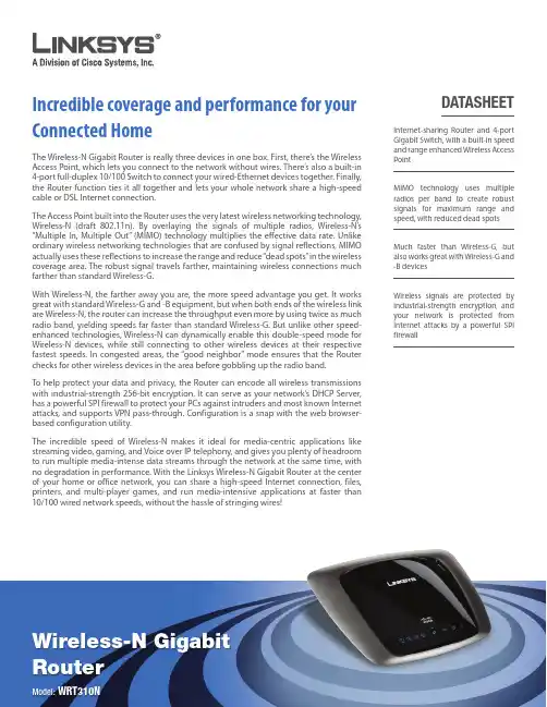
RouterModel: WRT310NIncredible coverage and performance for your Connected HomeThe Wireless-N Gigabit Router is really three devices in one box. First, there’s the Wireless Access Point, which lets you connect to the network without wires. There’s also a built-in 4-port full-duplex 10/100 Switch to connect your wired-Ethernet devices together. Finally, the Router function ties it all together and lets your whole network share a high-speed cable or DSL Internet connection.The Access Point built into the Router uses the very latest wireless networking technology, Wireless-N (draft 802.11n). By overlaying the signals of multiple radios, Wireless-N’s “Multiple In, Multiple Out” (MIMO) technology multiplies the effective data rate. Unlike ordinary wireless networking technologies that are confused by signal reflections, MIMO actually uses these reflections to increase the range and reduce “dead spots” in the wireless coverage area. The robust signal travels farther, maintaining wireless connections much farther than standard Wireless-G.With Wireless-N, the farther away you are, the more speed advantage you get. It works great with standard Wireless-G and -B equipment, but when both ends of the wireless link are Wireless-N, the router can increase the throughput even more by using twice as much radio band, yielding speeds far faster than standard Wireless-G. But unlike other speed-enhanced technologies, Wireless-N can dynamically enable this double-speed mode for Wireless-N devices, while still connecting to other wireless devices at their respective fastest speeds. In congested areas, the “good neighbor” mode ensures that the Router checks for other wireless devices in the area before gobbling up the radio band.To help protect your data and privacy, the Router can encode all wireless transmissions with industrial-strength 256-bit encryption. It can serve as your network’s DHCP Server, has a powerful SPI firewall to protect your PCs against intruders and most known Internet attacks, and supports VPN pass-through. Configuration is a snap with the web browser-based configuration utility.The incredible speed of Wireless-N makes it ideal for media-centric applications like streaming video, gaming, and Voice over IP telephony, and gives you plenty of headroom to run multiple media-intense data streams through the network at the same time, with no degradation in performance. With the Linksys Wireless-N Gigabit Router at the center of your home or office network, you can share a high-speed Internet connection, files, printers, and multi-player games, and run media-intensive applications at faster than 10/100 wired network speeds, without the hassle of stringing wires!DATASHEETInternet-sharing Router and 4-port Gigabit Switch, with a built-in speed and range enhanced Wireless Access PointMIMO technology uses multiple radios per band to create robust signals for maximum range and speed, with reduced dead spots Much faster than Wireless-G, but also works great with Wireless-G and -B devicesWireless signals are protected by industrial-strength encryption, and your network is protected from Internet attacks by a powerful SPIfirewallA Division of Cisco Systems, Inc. 121 TheoryIrvine, CA 92617 USA E-mail: *****************Web:Linksys products are available in more than 50 countries, supported by 12 Linksys Regional Offices throughout the world. For a complete list of local Linksys Sales and Technical Support contacts, visit our worldwide website at The maximum performance for wireless is derived from IEEE Standard 802.11 specifications. Actual performance can vary, including lower wireless network capacity, data throughput rate, range and coverage. Performance depends on many factors, conditions and variables, including distance from the access point, volume of network traffic, building materials and construction, operating system used, mix of wireless products used, interference and other adverse conditions.Check the product package and contents for specific features supported. Specifications are subject to change without notice.Linksys is a registered trademark or trademark of Cisco Systems, Inc. and/or its affiliates in the U.S. and certain other countries.Copyright © 2007 Cisco Systems, Inc. All rights reserved. Other brands and product names are trademarks or registered trademarks of their respective holders.7120510NC-JLModel: WRT310NSpecifications Model WRT310NStandards Draft 802.11n v2.0, 802.11g, 802.11b, 802.3, 802.3u Ports Power, Internet, Ethernet Buttons Reset, Wi-Fi Protected SetupLEDsEthernet (1-4), Wi-Fi Protected Setup, Wireless, Internet, Power Cabling Type CAT 5e # of Antennas 3Detachable (Y/N) No RF Pwr (EIRP) in dBm 17UPnP able/cert AbleSecurity Features Up to 256-Bit Wireless Encryption, SPI Firewall Security Key Bits 64, 128, 256Environmental Dimensions 7.95" x 1.34" x 6.30" (202 x 34 x 160 mm)Weight 11.99 oz (0.34 kg)Power12V, 1ACertification FCC, CE, IC-03Operating Temp. 32 to 104°F (0 to 40°C)Storage Temp.-4 to 158°F (-20 to 70°C)Operating Humidity 10 to 85% Noncondensing Storage Humidity5 to 90% NoncondensingPackage ContentsWireless-N Gigabit RouterSetup CD-ROM with Norton Internet Security User Guide on CD-ROM Quick InstallEthernet Network Cable Power AdapterMinimum RequirementsInternet Explorer 6.0 or Firefox 1.0CD-ROM DriveWindows XP or VistaWired or Wireless* Network Adapter*For optimum wireless performance, we recommend Linksys Wireless-N adapters (WPC300N, WMP300N, or WUSB300N).••••••••••FeaturesComplies with IEEE draft 802.11n standardsBlazing fast wireless speeds for high bandwidth applications such as video streaming or file sharing ••。
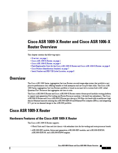
Cisco ASR1009-X Router and Cisco ASR1006-XRouter OverviewThis chapter contains the following topics:•Overview,on page1•Cisco ASR1009-X Router,on page1•Cisco ASR1006-X Router,on page4•Field-Replaceable Units for the Cisco ASR1009-X Router and Cisco ASR1006-X Router,on page6•Cisco Product Identification Standard,on page7•Serial Number and PID/VID Label Location,on page9OverviewThe Cisco ASR1000Series Aggregation Services Routers are mid-range edge routers that establish a newprice-to-performance class offering benefits to both enterprise and service providers alike.The Cisco ASR1000Series Aggregation Services Routers portfolio is based on an innovative custom-built ASIC calledQuantum Flow Processor that aggregates services at scale.The Cisco ASR1006-X Router and Cisco ASR1009-X Router create a future-proof modular routing platformto support next generation Forwarding and Route Processor modules with hardware redundancy.The CiscoASR1006-X Router and Cisco ASR1009-X Router provide up to200Gbps slot bandwidth to enable new highdensity Ethernet linecards utilizing the ASR1000-MIP100and Ethernet Port Adapters(EPAs),and integratingN+1power-on-demand design to the ASR1000portfolio.Cisco ASR1009-X RouterHardware Features of the Cisco ASR1009-X RouterThe Cisco ASR1009-X Router supports:•9Rack Units and3-line card slot chassis with redundant slots for forwarding and route processor boards•ASR1000-RP2module,future next generation ASR1000-RP3module,and ASR1000-ESP200,ASR1000-ESP100,and ASR1000-ESP40enginesFor information about the Cisco ASR1000-RP3module,see the Cisco ASR 1000Route Processor 3Installation and Configuration Guide .Note•Provides investment protection to support existing forwarding processor (ESP40,ESP100,and ESP200)•Provides future proof to support future next generation forwarding processor •100Gbps high density,modular Ethernet linecards (ASR1000MIP-100)•Three linecard slots support any of the following combinations:•ASR1000-SIP40with SPA•Ethernet linecard (ASR1000-6TGE and ASR1000-2T+20x1GE)•ASR1000-MIP100with EPA•New common fan modules to provide up to 30%better cooling for the chassis.Three fan modules per chassis•New power supplies are introduced for the chassis to provide greater power•Power-on-demand design with N+1power redundancy to meet any current and future power demand •Up to six AC or six DC power supplies that are aligned along the bottom of the chassis (power shelf)Cisco ASR 1009-X Overall Chassis Front ViewThe following figure shows the front of the Cisco ASR 1009-X Router.Cisco ASR 1009-X Router and Cisco ASR 1006-X Router OverviewCisco ASR 1009-X Overall Chassis Front ViewFigure 1:Cisco ASR 1009-X Router FrontViewSlot F06Slot F11Slot R07Slot R12Standby/ON switch 8Slot 23DB-25Alarm connector9Slot 14Power shelf that has power supplies from P0to P510Slot 05The Cisco ASR1009-X Router can support up to six AC or six DC power supplies.The chassis does not support mixed AC and DC configurationNoteCisco ASR 1009-X Chassis Rear ViewThe following figure shows the rear of the Cisco ASR 1009-X chassis with three fan modules and associated LEDs.Cisco ASR 1009-X Router and Cisco ASR 1006-X Router OverviewCisco ASR 1009-X Chassis Rear ViewFigure 2:Cisco ASR 1009-X Router RearViewFan Module 74Fan Module 8Status LED 1Fan Module 6Status LED 5Fan Module 82Fan Module 66Fan Module 7Status LED3The FAN OK LED can have three colors:Green,Red,and Amber.Green indicates Good,Red indicates Failed,and Amber indicates a Warning condition,when one or more fans may be operating at less than the expected speed,but not slow enough to call it a failure.NoteSee the Cisco ASR 1009-X Router and Cisco ASR 1006-X Router Power Supply LEDs section for more details.Cisco ASR 1006-X RouterHardware Features of the Cisco ASR 1006-X RouterThe Cisco ASR 1006-X Router supports:•6Rack Units and 2-line card slot chassis with redundant slots for forwarding and route processor boards •ASR1000-RP2module,future next generation ASR1000-RP3module,and ASR1000-ESP40and ASR1000-ESP100engines.For information about the Cisco ASR1000-RP3module,see the Cisco ASR 1000Route Processor 3Installation and Configuration Guide .Note•Provides investment protection to support existing forwarding processor (ESP40and ESP100)Cisco ASR 1009-X Router and Cisco ASR 1006-X Router OverviewCisco ASR 1006-X Router•Provides future proof to support future next generation forwarding processor.•100Gbps high density,modular Ethernet linecards (ASR1000-MIP100)•Two linecard slots support any of the following combinations:•ASR1000-SIP40with SPA•Ethernet linecard (ASR1000-6TGE and ASR1000-2T+20x1GE)•ASR1000-MIP100with EPA•New common fan modules to provide up to 30%better cooling for the chassis.Two fan modules per chassis.•New power supplies are introduced for the chassis to provide greater power•Power-on-demand design with N+1power redundancy to meet any current and future power demand.•Up to six AC or six DC power supplies that are aligned along the bottom of the chassis (power shelf)Cisco ASR 1006-X Overall Chassis Front ViewThe following figure shows the front of the Cisco ASR 1006-X Router.Figure 3:Cisco ASR 1006-X Router FrontViewSlot R06Slot F11Standby/ON switch 7Slot R12DB-25Alarm Connector8Slot 13Power shelf that has power supplies from P0to P59Slot 04Cisco ASR 1009-X Router and Cisco ASR 1006-X Router OverviewCisco ASR 1006-X Overall Chassis Front ViewSlot F05The Cisco ASR 1006-X Router can support up to six AC or six DC power supplies.The chassis does not support mixed AC and DC configuration.NoteCisco ASR 1006-X Chassis Rear ViewThe following figure shows the rear of the Cisco ASR 1006-X Router with two fan modules and associated LEDs.Figure 4:Cisco ASR 1006-X Router RearViewFan Module 6Status LED 3Fan Module 7Status LED 1Fan Module 64Fan Module 72The FAN OK LED can have three colors:Green,Red,and Amber.Green indicates Good,Red indicates Failed,and Amber indicates a Warning condition,when one or more fans may be operating at less than the expected speed,but not slow enough to call it a failure.NoteSee the Cisco ASR 1009-X Router and Cisco ASR 1006-X Router Power Supply LEDs section for more details.Field-Replaceable Units for the Cisco ASR 1009-X Router and Cisco ASR 1006-X RouterThe Cisco ASR 1009-X Router and Cisco ASR 1006-X Router has a number of FRUs.These include:•Route Processors •Forwarding ProcessorsCisco ASR 1009-X Router and Cisco ASR 1006-X Router OverviewCisco ASR 1006-X Chassis Rear View•Line Cards •SPAs •EPAs•AC and DC power supplies •FanmodulesFor information about the Cisco ASR1000-RP3module,see Cisco ASR 1000Route Processor 3Installation and Configuration Guide .NoteCisco Product Identification StandardThis section describes the Cisco products and services product identification standard.This feature provides you with the ability to effectively integrate and manage Cisco products in your network and business operations.Unique Device IdentifierThe Unique Device Identifier (UDI)is the Cisco product identification standard for hardware products.A product identification standard removes barriers to enterprise automation and can help you reduce operating expenses.The UDI provides a consistent electronic,physical,and associated business-to-business information product identification standard.The UDI is a combination of five data elements.The following table lists the UDI elements.Table 1:UDI ElementsDescriptionPhysical Visibility Electronic Visibility UDI Data Element Product ID,also known as product name,model name,product number YesYesPIDVersion IDYes Yes VID Serial number,the unique instance of the PID Yes Yes SN Type,such as chassis,slot,or power supply __Yes Entity Name Additional product information__YesProduct DescriptionThe combination of serial number and product ID (PID)is unique and consistent across all Cisco products.The PID that is coded on hardware is called a base product identifier.Cisco ASR 1009-X Router and Cisco ASR 1006-X Router OverviewCisco Product Identification StandardCisco ASR1009-X Router and Cisco ASR1006-X Router Overview Unique Device IdentifierAdditional orderable PIDs can be associated to a base PID.For instance,an orderable PID may describe apackaging configuration for a product or a bundled group of products sold,tested,and shipped together.Specific unique device identifier(UDI)benefits include the following:•Identifies:•Individual Cisco products in your networks•PIDs and serial numbers for service and replaceable products•Version IDs(VIDs)for product version visibility•Facilitates discovery of products subject to recall or upgrade•Enhances inventory automation of Cisco productsThe Cisco product identification standard provides the following features:•Version visibility—Cisco continuously improves products through feature additions.Product changesare indicated by incrementing the VID,which provides version visibility to help you understand andmanage product changes.VID management ensures consistency of changes from product to product.•Operating expense reduction—Cisco UDIs provide accurate and detailed network inventory information;identifying each Cisco product in a network element through a standard interface.Cisco operating systemscan view and use this data,allowing you to automate your electronic inventory.•Consistency across product layers—The UDIs are embedded in the hardware products and cannot beoverwritten.Operating and management systems discover UDIs through standard interfaces and displayUDIs in standard outputs.Standard interfaces include the IETF standard ENTITY-MIB.The show diag chassis eeprom detail command displays the PID,VID,PCB serial number,hardware revision,and other such information.The following is sample output from the show diag chassis eeprom detail command:ASR1009-X-2#show diag chassis eeprom detailMIDPLANE EEPROM data:EEPROM version:4Compatible Type:0xFFController Type:3172Hardware Revision:0.2PCB Part Number:73-16095-02Board Revision:01Deviation Number:0-0Fab Version:01PCB Serial Number:FXS1842043HRMA Test History:00RMA Number:0-0-0-0RMA History:00Top Assy.Part Number:68-5423-01CLEI Code:SAMPL00XYZProduct Identifier(PID):ASR1009-XVersion Identifier(VID):V00Chassis MAC Address:0c09.2a0f.0000MAC Address block size:320Chassis Serial Number:FXS1845Q1QTAsset ID:Vendor ID:00Environment Monitor Data:000800F8Environment Monitor Data :0411DF 000CASR1006-X-1#sho diag chassis eeprom detail MIDPLANE EEPROM data:EEPROM version :4Compatible Type :0xFF Controller Type :3171Hardware Revision :0.2PCB Part Number :73-16102-03Board Revision :01Deviation Number :0-0Fab Version:01PCB Serial Number :FXS1842046Z RMA Test History :00RMA Number :0-0-0-0RMA History:00Top Assy.Part Number :68-5481-01CLEI Code:SAMPL00XYZ Product Identifier (PID):ASR1006-X Version Identifier (VID):V00Chassis MAC Address :0c06.2a0e.0000MAC Address block size :256Chassis Serial Number :FXS1846Q415Asset ID :Vendor ID:00Environment Monitor Data :000800F8Environment Monitor Data:040F BE 002FCommon Language Equipment Identification (CLEI)code is a ten-digit character code that identifies a specific product.A CLEI code is applied to each part within a Cisco ASR 1009-X Router or Cisco ASR 1006-X Router as they are programmed in manufacturing for shipment to customers.NoteFor complete information on the product identification standard,see /go/udi/.Note Serial Number and PID/VID Label LocationThe following figure shows a Cisco ASR 1009-X Router along with the location of the serial number and the PID/VID label.Cisco ASR 1009-X Router and Cisco ASR 1006-X Router OverviewSerial Number and PID/VID Label LocationFigure 5:Cisco ASR 1009-X Router Serial Number and PID/VID LabelLocationThe following figure shows a Cisco ASR 1006-X Router along with the location of the serial number and the PID/VID label.Cisco ASR 1009-X Router and Cisco ASR 1006-X Router OverviewSerial Number and PID/VID Label LocationFigure 6:Cisco ASR 1006-X Router Serial Number and PID/VID LabelLocation1009-X 1006-X 11Cisco ASR 1009-X Router and Cisco ASR 1006-X Router OverviewSerial Number and PID/VID Label Location1009-X1006-X 12Cisco ASR1009-X Router and Cisco ASR1006-X Router OverviewSerial Number and PID/VID Label Location。
NVIDIA® Mellanox® ConnectX®-6 Dx SmartNIC is the industry’s most secure and advanced cloud network interface card to accelerate mission-critical data-center applications, such as security, virtualization, SDN/NFV, big data, machine learning, and storage. The SmartNIC provides up to two ports of 100 Gb/s Ethernet connectivity and delivers the highest return on investment (ROI) of any smart network interface card.ConnectX-6 Dx is a member of NVIDIA Mellanox’s world-class, award-winning ConnectX series of network adapters powered by leading 50 Gb/s (PAM4) and 25/10 Gb/s (NRZ) SerDes technology and novel capabilities that accelerate cloud and data-center payloads. SECURITY FROM ZERO TRUST TO HERO TRUSTIn an era where privacy of information is key and zero trust is the rule, ConnectX-6 Dx adapters offer a range of advanced built-in capabilities that bring security down to the endpoints with unprecedented performance and scalability, including:>Probes & DoS Attack Protection – ConnectX-6 Dx enables a hardware-based L4 firewall by offloading stateful connection tracking through Mellanox ASAP2 - Accelerated Switch and Packet Processing®.>NIC Security – Hardware Root-of-Trust (RoT) Secure Boot and secure firmware update using RSA cryptography, and cloning-protection, via a device-unique secret key. ADVANCED VIRTUALIZATIONConnectX-6 Dx delivers another level of innovation to enable building highly efficient virtualized cloud data centers:>Virtualization – Mellanox ASAP2 technology for vSwitch/vRouter hardware offloaddelivers orders of magnitude higher performance vs. software-based solutions.ConnectX-6 Dx ASAP2 offers both SR-IOV and VirtIO in-hardware offload capabilities, and supports up to 8 million rules.>Advanced Quality of Service – Includes traffic shaping and classification-baseddata policing. SmartNIC Portfolio>1/10/25/40/50/100 Gb/s Ethernet,PAM4/NRZ>PCIe low-profile form factor>QSFP56 connectors>PCIe Gen 3.0/4.0 x16 host interface Key Features>Up to 100 Gb/s bandwidth>Message rate of up to 215 Mpps>Sub 0.8 usec latency>Flexible programmable pipeline for new network flows>ASAP2 - Accelerated Switching and Packet Processing for virtual switches/routers >Overlay tunneling technologies>Hardware Root-of-Trust and secure firmware update>Connection Tracking offload>Advanced RoCE capabilities>Best in class PTP for TSN applications>GPUDirect® for GPU-to-GPU communication>Host chaining technology for economical rack design>Platform agnostic: x86, Power, Arm>ODCC compatibleNVIDIA MELLANOX CONNECTX-6 DX DELL EMC ETHERNET SMARTNICINDUSTRY-LEADING ROCEFollowing the Mellanox ConnectX tradition of industry-leading RoCE capabilities, ConnectX-6 Dx adds another layer of innovation to enable more scalable, resilient and easy-to-deploy RoCE solutions.>Zero Touch RoCE – Simplifying RoCE deployments, ConnectX-6 Dx allows RoCEpayloads to run seamlessly on existing networks without requiring special configuration on the network (no PFC, no ECN). New features in ConnectX-6 Dx ensure resiliency and efficiency at scale of such deployments.>Configurable Congestion Control – API to build user-defined congestion controlalgorithms, best serving various environments and RoCE and TCP/IP traffic patterns. BEST IN CLASS PTP FOR TIME SENSITIVE APPLICATIONS Mellanox offers a full IEEE 1588v2 PTP software solution as well as time sensitive related features called 5T45G. Mellanox PTP and 5T45G software solutions are designed to meet the most demanding PTP profiles. ConnectX-6 Dx incorporates an integrated Hardware Clock (PHC) that allows the device to achieve sub-20 usec accuracy while offering various timing related functions, including time-triggered scheduling or time-based SND accelerations (time based ASAP²). Furthermore, 5T45G technology enables software applications to transmit front-haul (ORAN) compatible in high bandwidth. The PTP solution supports slave clock, master clock, and boundary clock.EFFICIENT STORAGE SOLUTIONSWith its NVMe-oF target and initiator offloads, ConnectX-6 Dx brings further optimization to NVMe-oF, enhancing CPU utilization and scalability. Additionally, ConnectX-6 Dx supports hardware offload for ingress/egress of T10-DIF/PI/CRC32/CRC64 signatures. Solutions>Cloud-native, Web 2.0, hyperscale >Enterprise data-centers>Cyber security>Big data analytics>Scale-out compute and storage infrastructure>Telco and Network Function Virtualization (NFV)>Cloud storage>Machine Learning (ML) and Artificial Intelligence (AI)>Media and EntertainmentORDERING INFORMATION1 50G can be supported as either 2x25G NRZ or 1x50G PAM4 when using QSFP56.2 100G can be supported as either 4x25G NRZ or 2x50G PAM4 when using QSFP56. By default, the above products are shipped with a tall bracket mounted;a short bracket is included as an accessory.Learn more at /products/ethernet/connectx-smartnic© 2020 Mellanox Technologies. All rights reserved. NVIDIA, the NVIDIA logo, Mellanox, ConnectX, GPUDirect, Mellanox PeerDirect, and ASAP 2 - Accelerated Switch and Packet Processing are trademarks and/or registered trademarks of Mellanox Technologies Ltd. FEATURES *>IEEE 802.3cd, 50, 100 and 200 Gigabit Ethernet>IEEE 802.3bj, 802.3bm 100 Gigabit Ethernet>IEEE 802.3by, 25, 50 Gigabit Ethernet supporting all FEC modes>IEEE 802.3ba 40 Gigabit Ethernet >IEEE 802.3ae 10 Gigabit Ethernet >IEEE 802.3az Energy Efficient Ethernet (supports only “Fast-Wake” mode)>IEEE 802.3ap based auto-negotiation and KR startup >IEEE 802.3ad, 802.1AX Link Aggregation>IEEE 802.1Q, 802.1P VLAN tags and priority>IEEE 802.1Qaz (ETS) >IEEE 802.1Qbb (PFC) >IEEE 802.1Qbg>25/50 Ethernet Consortium “Low Latency FEC” for50GE/100GE/200GE PAM4 links >PCI Express Gen 3.0 and 4.0STANDARDS *Network Interface>2 x 25/50/100 GbEHost Interface>PCIe Gen 4.0, 3.0, 2.0, 1.1>16.0, 8.0, 5.0, 2.5 GT/s link rate >16 lanes of PCIe> MSI/MSI-X mechanisms >Advanced PCIe capabilitiesVirtualization/Cloud Native>Single Root IOV (SR-IOV) and VirtIO acceleration>Up to 1 K VFs per port >8 PFs>Support for tunneling>Encap/decap of VXLAN, NVGRE, Geneve, and more>Stateless offloads for Overlay tunnelsMellanox ASAP 2> SDN acceleration for:>Bare metal >Virtualization >Containers>Full hardware offload for OVS data plane>Flow update through RTE_Flow or TC_Flower >OpenStack support >Kubernetes support>Rich classification engine (L2 to L4) >Flex-Parser: user defined classification >Hardware offload for:>Connection tracking (L4 firewall) >NAT>Header rewrite >Mirroring >Sampling >Flow aging >Hierarchial QoS>Flow-based statisticsPlatform Security>Hardware root-of-trust >Secure firmware updateStateless Offloads>TCP/UDP/IP stateless offload >LSO, LRO, checksum offload>Receive Side Scaling (RSS) also on encapsulated packet>Transmit Side Scaling (TSS)>VLAN and MPLS tag insertion/stripping >Receive flow steeringAdvanced Timing & Synchronization>Advanced PTP>IEEE 1588v2 (any profile)>PTP Hardware Clock (PHC) (UTC format) >16 nsec accuracy>Line rate hardware timestamp (UTC format) >Time triggered scheduling >PTP based packet pacing>Time based SDN acceleration (ASAP 2) >Time Sensitive Networking (TSN)Storage Accelerations>NVMe over Fabric offloads for target>Storage protocols: iSER, NFSoRDMA, SMB Direct, NVMe-oF, and more >T-10 Dif/Signature HandoverRDMA over Converged Ethernet (RoCE)>RoCE v1/v2>Zero Touch RoCE: no ECN, no PFC >RoCE over overlay networks >Selective repeat>Programmable congestion control interface >GPUDirect ®>Burst buffer offloadManagement and Control>PLDM for Monitor and Control DSP0248 >PLDM for Firmware Update DSP026 >I 2C interface for device control and configurationRemote Boot>Remote boot over Ethernet >Remote boot over iSCSI>UEFI support for x86 and Arm servers >PXE boot* This section describes hardware features and capabilities. Please refer to the driver and firmware release notes for feature availability.。
May 2014All AirPorts and Apple TVs should be configured AHEAD of the demo – need AirPort Utility (for Windows or for Mac - /kb/dl1547 or check iTunes) and iTunes (https:///itunes/ ). You WILL need some sort of internet connection for both (more so for Apple TV). Most institutions have some sort of wifi network available. Furthermore, some businesses may have Apple IDs you can use in order to download and install the app on the iPad(s). You might not want to configure customer’s iPads using your own email address as an Apple ID, but for demos, it should be fine.To set up ZEISS Primostar HD and ZEISS Labscope1) Set up wireless router (AirPort – white) – connect white power cable to the back and to anoutlet.2) Set up ZEISS Primostar HD microscope – use the attached power supply to power themicroscope body. For the camera binocular head, attach the supplied “Y” USB cable to the back of the head and to the included wall charger adapter (only one end of the “Y” needed for this,when used in stand-alone mode, ie. not connected to a PC). The GREEN light on the side of the camera head should turn light up, assuming power is available. Attach the Ethernet cable from back of camera head to the back of the AirPort (not to the WAN port).You can add up to three microscopes directly to an AirPort. If you need to connect more microscopes, consider adding an unmanaged switch and connecting that the microscopes to that (and the switch to the router).NOTE: Labscope supports, in general, an unlimited number of microscopes. When there are more microscopes in the network than fit on one page in the Live tab, another page (andMay 2014another, etc.) will be added. They can be accessed by swiping left or right.The AirPort router (or any SOHO router for that matter) will have a hard time serving more than 20 live streams wirelessly though, because it will run out of bandwidth on the WLAN channel. Therefore for larger installations, multiple WLAN access points (could be AirPorts, but other 802.11n/ac access points will also work) will be needed, interconnected via LAN.3) Open Airport Utility on your computer (the iPad App does not detect unconfigured routers). Scanfor the AirPort (probably called “Base Station xxx”). If you have multiple routers to connect, click on the first one, configure it, and then repeat the process for the other routers later. (Thoserouters might need to be configured as Extenders – not covered here.) Click on the correctrouter and hit Continue.4) Name the wireless router. In this example, I called it “Carl Zeiss – Primostar HD router” and ifyou need to, add a number at the end, so you can tell all the routers apart. The password forALL router configurations should be “zeiss” (no quotations – case sensitive). Hit Continue.May 20145) Click I want to create a wireless network and Continue.6) Call the wireless network “Carl Zeiss”. Choose “no security” and specifically click Ignore in thewindow that pops up after hitting Continue.May 20147) Disable the guest network.8) Select I am not ready to connect to the Internet right now (unless you are, but thisconfiguration is for a stand-alone system).9) Click Update and the device will restart.10) When looking for DNS Servers, simply click Continue. You will get a warning. You MUST hitIgnore in order for the status light on the AirPort to turn GREEN and for the connections to ultimately work.11) Click Update again.May 201412) Setup is now complete. You should be returned to the home screen which lists all availableAirPorts in the area. You can close the AirPort Utility at this point.13) Set up the iPad – If you DO have a wireless network available to you – Start the iPad (notconnected to a computer). Choose a language and a country. When prompted to connect to an existing WiFi network – if you have an existing WiFi network, you may connect to it for theconfiguration to proceed. Disable Location Services. Select “Set up as new iPad.” Whenprompted for an Apple ID – you can skip this step. Agree to the Terms of Service. You maycreate a passcode for the iPad at this time, or can do so later. Don’t use Siri. Don’t senddiagnostics. Click Get Started to reach the Home screen. Open the App Store and search for“Labscope” to download it. You will be prompted for an Apple ID. You may use your own Apple ID, or you may create a fake one (although you’ll need a real email address to receive theverification email). You can associate a maximum of 10 iPads with this Apple ID, so it is likely that one fake account should cover your needs (you could use both your old and new ZEISSemail addresses, for instance, to add the app to 20 iPads). If you set up the iPad in this manner, simply install Labscope directly from the iPad.14) Set up the iPad - If you DO NOT have a wireless network available to you – Start the iPad.On the iPad, select a language and country. Select “Connect via iTunes” when prompted for a network connection. The iPad will prompt you to connect the included USB charger cable to the iPad and a computer that has iTunes installed. iTunes and the iPad will load automatically. InMay 2014iTunes, select “Set up as new iPad” and click Continue. The iPad will now progress to Location Services. Disable Location Services. Select “Set up as new iPad.” When prompted for an Apple ID – you can skip this step. Agree to the Terms of Service. You may create a passcode for the iPad at this time, or can do so later. Don’t use Siri. Don’t send diagnostics. Click Get Started to reach the Home screen. From the iTunes Store, search for and download Labscope. You will be prompted for an Apple ID. You may use your own Apple ID, or you may create a fake one(although you’ll need a real email address to receive the verification email). You can associate a maximum of 10 iPads with this Apple ID, so it is likely that one fake account should cover your needs (you could use both your old and new ZEISS email addresses, for instance, to add theapp to 20 iPads). If you set up the iPad in this manner, switch to the Apps tab in iTunes andclick Install next to Labscope, then click Apply at the bottom of the window. iTunes will then sync with the iPad and install the application.15) On the iPad, open the Settings. Click WiFi and locate the “Carl Zeiss” network that you created.Click on that network to connect to it, and type in a password as necessary. Return to the Home screen and start Labscope.16) On the overview tab (top tab, left side), you will see two Virtual Microscopes and eventually, youshould see Primostar HDs. Initially, each one may have a strange number associated with it.17) Click on the gear, located in the lower-right corner of each microscope, to configure thatmicroscope. On the left side of the window, you will be able to choose if this setup is forPrimostar HD or AxioCam ERc 5s Rev. 2 (compound or stereo). For “Microscope name,” youmay call the microscope whatever you want, or along any naming convention. For directidentification, you might want to name the microscope by the Serial Number on the back of the microscope body, so there can be no confusion which microscope you are receiving imagesfrom. Configure other information about the setup as appropriate. You may lock thisconfiguration, if desired.May 2014To connect ZEISS Primostar HD directly to a computer1) Connect the provided “Y” USB cable to the back of the camera head. Connect BOTH ends atthe opposite end of the cable to the computer. If DVD 52 is installed already, the driver should automatically install, as with other USB devices. In Device Manager, the camera will show up as such:2) Open ZEN (lite, Pro). The camera will show under the Active Camera dropdown as an“AxioCam ERc5s”.Operating Notes•NOTE: The HD head CANNOT be connected to an iPad and to a computer simultaneously.•NOTE: SD Card must be formatted to FAT32 prior to recording images.•NOTE: SD Card can be read by computer if HD head is connected to a PC. (It might prompt you to format the SD Card – DO NOT DO THIS. The images are available in the removable drivethat now shows up in Computer.) Images can no longer be captured to the SD Card; they must now be captured using ZEN.•NOTE: SD Card and AirPort connection are possible simultaneously. Labscope will simply showa “Snap Delay” screen. If you remove the SD Card in the middle of shooting, you must closeand re-open Labscope app. If you re-insert the SD Card, you must close Labscope via double-tapping the Home button (from the Home screen on the iPad). Re-insert the SD Card and re-open the app. Images snapped from Labscope will be saved to the iPad; images snapped via the “Snap” button the camera head will be saved to the SD Card.。
he H3C S12500 DataCenter Cloud Core Switch Series is designed for cloud services data centers. It provides the following features:H3C S12500 DataCenter Cloud Core Switch SeriesCLOS+ multi-grade multi-plane architectureIndustry’s highest performance core switch with 768 line-speed 40G/100G interface per chassisIntegration of IRF2 (Intelligent Resilient Framework version 2), IRF3 (Intelligent Resilient Framework version 3) and MDC (Multi-tenant Device Context) to implement virtual resource poolsDistributed ingress buffers (200 ms) to accommodate burst traffic in data centersIndependent control, detection, and maintenance engines to implement 50ms failover and powerful control capabilities The S12500 switch series includes S12508, S12518, S12510-X, S12516-X, 12504X-AF, 12508X-AF, 12512X-AF andS12516X-AF, which meet various port density and performance requirements. The S12500 switch series can work with H3C routers, switches, security devices, IMC, and H3Cloud to provide a wide variety solutionsHigh Availability (HA) - Patented hot standby technologyprovides data backup and non-stop forwarding on the control plane and data plane. It improves availability and performance eliminating single-point of failures, and ensure service continuity Distribution - Multi-chassis link aggregation to enable loadsharing and backup over multiple uplinks, improving redundancy and link utilizationEasy Management - A single IP address to manage the whole IRF fabric, which simplifies device and topology management, improving operating efficiency, and lowering network maintenance costTVirtualization technologies - IRF2Virtualization technologies - IRF3Features Advanced CLOS+ multi-grade multi-plane switching architecture•••••••••••••CLOS+ multi-grade multi-plane architecture, midplane free design, providing continuous bandwidth upgrade capability Supports industry first 48-port 40GE/ 100GE interfaces and can meet the existing and future application requirements of data centers•Adopts independent switching fabric modules and MPU engines to improve device availability and ensure bandwidth expansion••Increased I/O ports and centralized maintenance and managementReduced network management nodes Simplified cable deployment Data plane virtualizationIRF2 can virtualize up to four S12500 switches into one logical IRF fabric. IRF2 delivers the following benefits:IRF3 virtualizes core and access switches into one logical device. IRF3 delivers the following benefits:OverviewIndependent control engine - Uses a powerful CPU system that can efficiently process protocol and control packets, providing refined control for protocol packets and comprehensive protection against protocol packet attacks Independent detection engine - Provides highly reliable Fast Fault Detection and Restoration (FFDR) such as BFD and OAM, which can interact with protocols on the control plane toimplement millisecond-level failover and convergence, ensuring service continuityIndependent maintenance engine - Uses an intelligent Embedded Maintenance Subsystem (EMS), a CPU system that provides smart power management, including sequential power-on and power-off and device status check. Sequential power-on and power-off reduces power impulse, electromagnetic radiation, power consumption, and extends the device lifespan•••••••••••TRILL/SPB - Designed for building large flat Layer 2 networks for data centers to accommodate more servers. TRILL or SPB integrates the simplicity and flexibility of Layer 2 with the stability, scalability, and high performance of Layer 3EVI - EVI is a MAC-in-IP technology that provides Layer 2connectivity between distant Layer 2 network sites across an IP routed network. It is used for connecting geographically dispersed sites of a virtualized large-scale data center that requires Layer 2 adjacencyFCOE - Integrates heterogeneous LANs and storage networks in data centers. FCOE and CEE integrate data, computing, and storage networks in data centers, reducing the costs for building and expanding data centersVXLAN (Virtual Extensible LAN) —VXLAN uses a MAC-in-UDP encapsulation method where the original Layer 2 package is added with a VXLAN header, and is then placed in a UDP-IP packet. With the help of MAC-in-UDP encapsulation, VXLAN tunnels Layer 2 network over Layer 3 network which provides two major benefits: higher scalability of Layer 2 segmentation and better utilization of available network pathsMP-BGP EVPN (Multiprotocol Border Gateway Protocol Ethernet Virtual Private Network) uses standard-based BGP protocol as the control plane for VXLAN overlay networks, providing BGP based VTEP auto peer discovery and end-host reachabilityinformation distribution. MP-BGP EVPN delivers many benefits, such as eliminating traffic flooding, reducing full meshrequirements between VTEPs via the introduction of BGP RR, achieving optimal flow based end to end load sharing and more Large capacities for storing ARP/ND, MAC, and ACL entriesDC-oriented features••••••DC-class HAInnovative multi-engine designFFDR provides BFD and OAM functions to implement fast failover and convergence. The following lists the DC-class HA features:Independent control, detection, and maintenance engines provide powerful control capability and millisecond-level HA:BFD for VRRP/BGP/IS-IS/RIP/OSPF/RSVP/static routing NSR/GR for OSFP/BGP/IS-IS/RSVPSeparation of control and data planes through independent control engine and switching fabric module 1+1 redundancy for control engines N+1 redundancy for switch fabric modules 1+1 redundancy for fan trays N+M redundancy for power modulesSupports a large numbers of ACLs while ensuring line-speed forwarding. ACLs can identify and control L2/IPv4/IPv6/MPLS traffic by using combinations of packet fieldsMulti-level security protectionThe S12500 switch series use QoS policies to filter and limit traffic from data plane to control plane. During a DoS attack, the switch can identify and protect important packets and discard attack packets, ensuring normal operation••Virtualization technologies - MDCMDC virtualizes one S12500 switch into multiple logicalswitches, enabling multiple services to share one core switch. The 1:N virtualization maximizes switch utilization, reduces network TCO, and ensures secure isolation of services••••Distributed buffering and precise QoSDistributed ingress buffers accommodate burst traffic. Each port performs a precise bandwidth assignment and traffic shaping for incoming traffic, and distributes the traffic to ingress buffers. Distributed buffering can fully utilize the buffers of line cards to ensure best buffering performanceA network model change from C/S to B/S leads to increased volumes of burst traffic. Network devices must have larger buffering capabilities to support this. The S12500 series supports 200ms buffering of burst traffic per 10G interface, which can meet the burst traffic requirements of large data centersEach chip can support 4GB buffer, maximum of 24GB buffer per line cardEach line card supports a maximum of 96K hardware queues, refined QoS, and traffic management. QoS can assign different priorities and queues to different users to provide differentiated services•••Comprehensive maintenance and monitoringOnline state monitoring - Uses a dedicated engine to monitor the state of switch fabric modules, backplane channels, service communication channels, key chips, and storage. Once a failure occurs, it reports the failure to the system through EMS Card isolation - Isolates specified cards from the forwarding plane. The isolated cards still work on the control plane,allowing the user to perform management operations such as real-time diagnosis and CPLD upgrade on the isolated cards without affecting system operationEthernet OAM provides multiple device-level and network-level fault detection methods••OAAOAA provides an open service platform that supports multiple service cards, including next generation firewall and netstream cards. The integration of these cards to the switch allows for unified network security solutionsGreenIntelligent EMS engine system - Provides smart power management that supports sequential power-on andpower-off and device status check. Sequential power-on and power-off reduces power impulse and electromagneticradiation, and increases the lifetime of the device. Additionally, device status checks can isolate faulty and idle cards to reduce power consumption••••Smart fan management - Collects fan temperature, calculates fan speed, and assigns the calculated speed to the fan tray. In addition, it detects fan speeds, fault alarms, and performs speed adjustment based on configurations and area, reducing power consumption and noise, increasing the fan's lifetimeInternal interface monitoring - Automatically shuts down unused internal interfaces to reduce power consumptionRoHS compliance - The S12500 switch series meets the EU RoHS safety standardsThe S12500 switch series is designed with front to back air flow, satisfying highly efficient heat dissipation requirements in data centreSpecificationsEnterprise DC applicationProvides large-capacity forwarding through its multi-level switching fabric to completely meet the traffic forwarding requirements of large data centers.Provides HA mechanisms such as BFD and FRR to ensure the availability of data center networks.Work with other H3C switches, routers and security devices to offer a complete data center solution.•••As core devices in data center networks, the S12500 series features the following:resources10GE Base-Tserver10GE server S10500S5820V2-52QF 10G server GE serverFC storageIDC ApplicationH3C Technologies Co. Limited Add: Room 2301, 23/F,Lee Garden Two, 28 Yun Ping Rd, Causeway Bay, Hong Kong Tel: 2501 1111 Fax: 2537 1149Service Hotline: 2907 0456Copyright © 2016 by H3C Technologies Co., LimitedAll product photography in this literature is intended for reference only. All rights reserved. No part of this document may be reproduced or transmitted in any form, by any company or person and product names may be trademarks of their respective companies. While every effort is made to ensure the information given is accurate, H3C Technologies Co., Limited does not hold liability for any errors or mistakes whichProvides up to 768 line-speed 40G/100G interfaces to meet the performance requirements of new generation IDCs.Supports virtualization technologies such as IRF and TRILL to implement large-scale network deployment.Supports large scale of MAC and ARP entries to meet flat network requirements.As the core devices in IDC networks, the S12500 switch series features the following:•••。
TroubleshootingSpecificationThe IODD file can be downloaded from the SMC website (URL ).Refer to the product catalogue or SMC website (URL ) for more detailed information about product specifications.DimensionsRefer to the product catalogue or SMC website (URL ) for more detailed information about dimensions.than above are displayed, please contact SMC.Error indication functionThis function is to display error location and content when a problem or error has occurred.Snap shot functionThe current flow/temperature value can be stored to the switch output ON/OFF set point.When the set value and hysteresis are set, press the UP and DOWN buttons for 1 second or longer simultaneously. Then, the set value of the sub display (right) shows [- - -], and then values corresponding to the current flow/temperature are automatically displayed.Peak/bottom value indicationThe maximum (minimum) flow/temperature when the power is supplied is detected and updated.The value can be displayed on the sub display by pressing the UP or DOWN button in measurement mode.Key-lock functionTo set this function, refer to SMC website (URL ) for more detailed information or contact us.MaintenanceHow to reset the product after a power cut or when the power has been unexpectedly removedThe settings of the product are retained from before the power cut or de-energizing.The output condition also recovers to that before the power cut or de-energizing,but may change depending on the operating environment.Therefore, check the safety of the whole system before operating the product.Function selection modeSelect to display the function to be change [F mode to return to measurement mode.The function number is increased and decreased by the UP and DOWN buttons.Display the required function number and press the SET button.Default settingsThe default settings are provided as follows. If these settings are acceptable,retain for use. To change setting, refer to SMC website(URL ) for more detailed information or contact us.Display of sub screenIn measurement mode, the display of the sub screen can be temporarily changed by pressing the UP or DOWN buttons.After 30 seconds, it will automatically reset to the display selected in [F10].(Example shown is for 16 L/min type)∗: Arbitrary display∗: An arbitrary display can be added to the sub display by setting in [F10].If the sub display is switched during the arbitrary display, the display will return to the arbitrary display 30 seconds later.(The default setting does not include arbitrary display).Refer to the SMC website (URL ) for more detailed information about product troubleshooting.Note: Specifications are subject to change without prior notice and any obligation on the part of the manufacturer.© 2019 SMC Corporation All Rights Reserved Akihabara UDX 15F, 4-14-1, Sotokanda, Chiyoda-ku, Tokyo 101-0021, JAPAN Phone: +81 3-5207-8249 Fax: +81 3-5298-5362URL PF ※※-OMW0011Safety InstructionsFlow SettingInstallationBracket mounting (PF3W704/720/740)Mount the product (with bracket) usingthe mounting screws supplied (M4 x 4 pcs.).For models with flow adjustment valve attached, fix using 8 mounting screws.Bracket thickness is approx. 1.5 mm.Measurement modeThe mode in which the flow is detected and displayed, and the switch function is operating.This is the basic operating mode; other modes should be selected for set-point and other function setting changes.Approx. 3 seconds for this period)Mounting and InstallationInstallation•Use the product within the specified operating pressure and temperature range.•Proof pressure could vary according to the fluid temperature.Check the characteristics data for operating pressure and proof pressure.(4-pins)(Option)(Option)Direct mounting (PF3W704/720/740)Mount using the self tapping screws(nominal size: 3.0 x 4 pcs.) for installation.For models with flow adjustment valveattached, mount using 8 self tapping screws.The tightening torque must be 0.5 to 0.7 Nm.PipingWhen connecting piping to the product, a spanner should be used on the metal piping attachment only.Using a spanner on other parts may damage the product.In particular, do not let the spanner come into contact with the M8 connector.The connector can be easily damaged.If the tightening torque is exceeded, the product can be broken. If the correct tightening torque is not applied, the fittings may become loose.Avoid any sealing tape getting inside the piping.Ensure there is no leakage from loose piping.3/820.9 mm 1/223.9 mm 3/429.9 mm After hand tightening the piping, apply a spanner of the correct size to the spanner flats on the product, and tighten it for 2 to 3 rotations.Direct mounting (PF3W711)Mount using the self tapping screws(nominal size: 4.0 x 4 pcs.) for installation.The tightening torque must be 1.0 to 1.2 Nm.The self tapping screws should not be re-used.Refer to the outline dimension drawing for mounting hole size.Refer to the product catalogue or SMC website (URL )for more detailed information.WiringWiring of connectorConnections should only be made with the power supply turned off.Use separate routes for the Flow switch wiring and any power or high voltage wiring. Otherwise, malfunction may result due to noise.Ensure that the FG terminal is connected to ground when using a commercially available switch-mode power supply. When a switch-mode power supply isconnected to the product, switching noise will be superimposed and the product specification can no longer be met. This can be prevented by inserting a noise filter, such as a line noise filter and ferrite core, between the switch-mode power supply and the product, or by using a series power supply instead of a 141 mmHow to adjust the flow rate(when a flow adjustment valve is mounted)to the target value.(2) Be sure to confirm that there is no fluid leakagegenerated after adjustment.(When fluid leakage is generated, open and close the valve several times for re-adjustment, and confirm that there is no fluid leakage.)(3) Tighten the lock ring to fix the valve as necessary.The flow adjustment valve is not designed forapplications that require daily and repetitive adjustment.If the valve is adjusted frequently, fluid may leak due to wear of the internal seal.BodyDisplayBracket mounting (PF3W711)Mount the product (with bracket) usingthe mounting screws supplied (M5 x 4 pcs.).Bracket thickness is approx. 2 mm.2. Press the UP or DOWN button to change the set value.The UP button is to increase and the DOWN button is to decrease the set value.•Press the UP button once to increase by one digit, or press and hold to continuously increase.3. Press the SET button to finish the setting.•Press the DOWN button once todecrease by one digit, or press and hold to continuously decrease.Mounting•Never mount the product in a location where it will be used as a support.•Mount the product so that the fluid flows in the direction indicated by the arrow on the side of the body.•Check the flow characteristics data for pressure loss and the straight inlet pipe length effect on accuracy, to determine inlet piping requirements.•Do not sharply reduce the piping size.•The monitor with integrated display can be rotated. It can be set at 90o intervals clock and anticlockwise, and also at 45o and 225o clockwise. Rotating the display with excessive force will damage the end stop.∗: When using the lead wire with M8 connector included with the PF3W7 series.Refer to the product catalogue or SMC website (URL )for more detailed information.Before UseDigital Flow Switch(Integrated display type)PF3W7##-LThank you for purchasing an SMC PF3W7##-L Series Digital Flow Switch (Integrated display type).Please read this manual carefully before operating the product and make sure you understand its capabilities and limitations. Please keep this manual handy for future reference.Safety InstructionsThese safety instructions are intended to prevent hazardous situations and/or equipment damage.These instructions indicate the level of potential hazard with the labels of"Caution", "Warning" or "Danger". They are all important notes for safety and must be followed in addition to International standards (ISO/IEC) and other safety regulations.OperatorWidth across flats of attachment1. Press the SET button in measurement mode to display set values.(The item to be changed is displayed on the sub display)Tighten the connector by hand.The switch turns on within a set flow range (from P1L to P1H) during window comparator mode. Set P1L (switch lower limit) and P1H (switch upper limit) using the setting procedure above.When reversed output is selected, the main screen displays [n1L] and [n1H].To set accumulated output functions, refer to the product catalogue orSMC website (URL ) for more detailed information.For models with 2 outputs, [P_2] or [n_2] will be displayed. Set as above.For models with the temperature sensor attached, [ tn] will be displayed.When the fluid temperature falls below the set value, the output turns ON.∗: If a button operation is not performed for 30 seconds during the change of setting, the set value will start flashing.。
High performance specifications and extensive international certifications ensure that the SolaHD SDN-C is suitablefor the most extreme environments, including hazardous locations and off-shore applications. Features like wide operating temperature range, power boost capability,and adjustable output voltage ensure reliable operation in the harshest industrial environments. Parallel operation, extensive LED diagnostics, and universal AC or DC input voltage simplify installation and maintenance. For added reliability, the SDN-C power supplies can be used with theSolaHD Redundancy modules to provide redundant power supply operation.Applications• Industrial Automation• Process Control• Material Handling and Conveyors• Hazardous Locations• Marine ApplicationsFeatures• Extensive international hazardous location certifications, including Class I, Zone 2, ATEX, IECEx, ExEAC.Hazardous location temperature code (T-Code) ratingof T4.• International off-shore certifications, including ABS and DNV-GL• PowerBoost TM enables short duration overloadcapability, to start loads with high inrush current• Three LEDs provide extensive diagnostics• Dual output terminals for convenience in wiring• DC OK relay to provide diagnostic information to a PLC, controller, or monitoring system• Universal AC and DC input voltages to accommodateglobal requirements• Wide operating temperature range accommodates both extreme hot and extreme cold environments• Active Power Factor Correction on most models• Parallel operation capability standard• Supports redundant power supply operation usingoptional SDN™ Redundancy modules• 5-year limited warranty Certifications and Compliances *All Models• Listed, Ind. Control Equipment, E61379- UL 508, CSA C22.2 No. 107.1•UL 60950UL Recognized Component, ITE, E137632- UL 60950-1/CSA C22.2 No. 60950-1, 2nd Edition •UL 60950UL Recognized Component, Class I, Div 2;Class I Zone 2; T4 E234790•EMC and- Low Voltage Directive- IEC/EN60950-1, 2nd Edition• RoHS CompliantModels SDN 5-24-100C, SDN 10-24-100C, SDN 16-12-100C, SDN 20-24-100C, SDN 40-24-100C, SDN 5-24-480C, SDN 10-24-480C, SDN 20-24-480CD•UL 60950UL Recognized Component, Haz. Loc., E234790 - UL60079-0/CSA E60079-0, UL 60079-15, CSAE60079-15- Class I, Zone 2, AEx nA nC IIC, Ex nA nC IIC•- EN60079-0, EN60079-7, EN60079-15-• IECEx Certified- IEC 60079-0, IEC 60079-7, IEC 60079-15- Ex ec nC IIC GcModels SDN 5-24-100C, SDN 10-24-100C, SDN 16-12-100C, SDN 20-24-100C, SDN 40-24-100C, SDN 5-24-480C, SDN 10-24-480C• Type ApprovalModels SDN 5-24-100C, SDN 10-24-100C, SDN 16-12-100C, SDNModels SDN 5-24-100C, SDN 10-24-100C, SDN 20-24-100C, SDN 40-24-100C• CertifiedSDN-C Performance DIN Rail Series* Refer to user manual for installation requirements when used in hazardous locations.E61379UL 60950E137632E234790IECExThe SolaHD DifferenceRugged metal housingMultiple output connections for ease of wiring multiple devicesSingle or parallel use selectable by userClearly labeled front panelMultiple certifications for versatility in applicationsAutomatically adjusts for global Input voltagesNarrow width saves panel spaceNo internal fan, no extra cooling required in any power levelAdjustable output voltageDC OK Relay Terminals provide diagnostic information to a PLC or controllerVisual LED diagnostics show input and output status (see table below)LED Light Status ConditionsRelated Products• SDN-C Redundancy Modules• IP67 SCP-X Extreme Environment Series • SDU UPS Accessories• Chassis Mount BracketsSDN-C Specifications (Single Phase)1. Input current ratings are conservatively specified with low AC input, worst case efficiency and power factor.2. Losses are heat dissipation in watts at full load, nominal AC input line.3. Ripple/noise is stated as typical values when measured with a 20 MHz, bandwidth scope and 50 Ohm resistor.4. All models are capable of paralleling. For redundant operation, please use external Redundancy module. Only the 40A uses Active paralleling scheme. Please refer to usermanual for details.5. Peak current is calculated at nominal voltage levels.6. Contact tech support for operation at -40°C.SDN-C Specifications (Single Phase) continued7. Screw terminals. Use only one copper wire per terminal. Non-ratcheting torque driver recommended.8. SDN 40-24-100C only — Provided with Signal Mode terminal block which includes the following features: DC OK, Ground signal, PS ON, I_share connection. Refer to SignalsManual for terminal connection details..SDN-C Specifications (Three Phase)1. In the event of a phase loss, the power supply will continue to operate normally. However, the resulting lower rectified RMS voltage can cause excessive heat build up, which may eventually cause the unitto shut down if maximum operating temperature is exceeded.2. Input current ratings are specified with low AC 3-phase input, line conditions, worst case efficiency values and power factor spikes. Input current at nominal AC 3-phase input will typically be half thesevalues.3. Losses are heat dissipation in watts at full load, nominal line.4. 24-28 Vdc adjustable guaranteed at full load.5. Ripple/noise is stated as typical values when measured with a 20 MHZ, bandwidth scope and 50 Ohm resistor6. All models are capable of paralleling. For redundant operation, please use external Redundancy module. Only the 40A uses active paralleling scheme. Please refer to user manual for details.7. SDN 20 and SDN 40 are capable of delivering 150% load for approximately 4s before the unit will go to HICCUP mode. SDN 5 and 10 will maintain minimum 4s to deliver 150% load then drops to almostzero Vout. The output voltage will immediately drop to almost zero when load rises above 150%.8. Contact Tech Support for operation -40°C.SDN-C Specifications (Three Phase)9. Screw terminals. Use only one copper wire per terminal. Non-ratcheting torque driver recommended.10. SDN 40-24-480C only: Output signaling terminal block features (Shut down, Power Good, Current Monitor, Current Balance, signal GND). Please refer to Signals Manualfor details.SDN-C Series DimensionsSDN 40-24-480C DimensionsSDN 40-24-100C and SDN 40-24-480C output signaling terminal block features: Shut Down, Power Good, Current Monitor, Current Balance, GND, and active current sharing through I_SHARE connectors (See Signals Manual for connection information).4.85 i n . [13 m m ] 1.97 in.[50.0 mm]4.36 in. [110.8 mm]W D Voltage adjustment potentiometer located on top of power supplySDN 40-24-100C Dimensions5.51 i n . (139.96 m m )WDD + 0.54 in (13.80 mm)SignalConnectorPower Supply HSolaHD SDN-C power supplies are designed to be easily and reliably mounted to DIN rail. For applications requiring mounting the power supply directly to the panel, optional Panel Mount Adapter Brackets are available.SDN-PMBRK2SDN-C Series MountingPanel mounting of SDN-C power supplies is simplified by using an optional Panel Mounting Bracket kit. Each kit comes with two brackets for modifying one power supply. Choose the appropriate bracket kit based on the power supply model in the tables below. Note that the Panel Mount bracket will add approximately 2-4mm in depth, compared to DIN rail mounting. Refer to the manual that comes with the bracket kit for detailed instructions on assembly and mounting.Detachment from DIN Rail:with M3X8 mm Phillips Screw and lock washer (use 7kgf torque).Top View 3D ViewDIN BracketM3X8 mmPhillips ScrewBack ViewPower Supply AccessoriesSDN-PMBRK3Panel Mount Brackets Installation ManualDimensions in Inches (Millimeters)2. Reta of th3. Pus with7983472006511.93 (49.0)Top View 3D View Top View 3D ViewDimensions - in. (mm)Dimensions - in. (mm)。