system verilog 初探
- 格式:docx
- 大小:28.77 KB
- 文档页数:14
systemverilog search()用法SystemVerilog search()用法SystemVerilog的search()函数是一种用于在字符串中搜索子字符串的强大工具。
它可以在字符串中定位目标子字符串,并返回其出现的位置。
在本文中,我将介绍search()函数的一些常见用法,并提供详细的解释。
1. search()函数的基本用法search()函数的基本语法如下:int search(string haystack, string needle);其中,haystack是要搜索的字符串,needle是目标子字符串。
search()函数返回目标子字符串在搜索字符串中的位置,如果找不到目标子字符串,则返回-1。
以下是search()函数的一个简单示例:string s = "Hello World";int pos = search(s, "World");在上述代码中,search()函数将在字符串s中搜索子字符串”World”。
如果找到该子字符串,则将返回它在字符串中的位置。
在本例中,pos将被赋值为6,表示”World”在字符串中的起始位置。
2. search()函数的高级用法搜索多个目标子字符串search()函数允许同时搜索多个目标子字符串。
你可以使用竖线(|)将这些目标子字符串分隔开。
以下是一个示例:string s = "Hello World";int pos = search(s, "Hello | World");在上述示例中,search()函数将在字符串中搜索”Hello”或”World”。
如果找到任何一个目标子字符串,则将返回它在字符串中的位置。
在这个例子中,pos将被赋值为0,表示”Hello”在字符串中的起始位置。
指定搜索的起始位置通过使用第三个参数,你可以指定search()函数开始搜索的位置。
系统Verilog是一种硬件描述语言(HDL),用于描述数字电路。
它包含了Verilog的所有特性,并添加了一些新的特性。
这些新的特性包括在设计中引入了数据类型的定义,更好地支持设计的抽象,以及更自然地支持设计的层次式描述。
在本文中,我们将深入了解System Verilog标准。
1. 介绍System Verilog标准System Verilog是IEEE标准1800,最初是由Accellera组织进行开发的。
它于2005年发行,是Verilog HDL的扩展,它添加了许多新的特性,使得它更适合于硬件验证和设计。
2. System Verilog的特性System Verilog添加了许多新的特性,以提高Verilog HDL的功能。
其中一些主要特性包括:a. 对象导向编程:System Verilog引入了面向对象的编程范式,使得设计和验证更加抽象和灵活。
b. 增强了数据类型和操作:System Verilog引入了更多的数据类型和操作,更好地支持设计和验证的需求。
c. 增加了随机性:System Verilog引入了随机性,使得验证更加全面和高效。
3. System Verilog在硬件验证中的应用System Verilog的特性使得它在硬件验证中应用广泛。
它提供了丰富的验证方法和工具,包括:a. 事务级建模(TLM):System Verilog提供了TLM的支持,使得验证更加抽象和高效。
b. Constrained随机验证:System Verilog引入了constrained random的验证方法,使得验证更加全面和高效。
c. Coverage驱动验证:System Verilog提供了coverage驱动的验证方法,使得验证更加全面和高效。
4. System Verilog在硬件设计中的应用除了在硬件验证中应用广泛外,System Verilog在硬件设计中也有着广泛的应用。
SystemVerilog语言知识介绍SystemVerilog是一种硬件描述与验证语言(HDVL),它基于IEEE 1364-2001 Verilog硬件描述语言(HDL),并对其进行了扩展,包含扩充了C语言数据类型、结构、压缩与非压缩数组、接口、断言等等,这些都使得SystemVeri log在一个更高的抽象层次上提高了设计建模的能力。
Syst emVerilog由Accellera开发,它要紧定位在芯片的实现与验证流程上,并为系统级的设计流程提供了强大的连接能力。
下面我们从几个方面对SystemVerilog所作的增强进行简要的介绍,期望能够通过这个介绍使大家对SystemVeril og有一个概括性的熟悉。
1. 接口(Interface)Verilog模块之间的连接是通过模块端口进行的。
为了给构成设计的各个模块定义端口,我们务必对期望的硬件设计有一个全面的认识。
不幸的是,在设计的早期,我们很难把握设计的细节。
而且,一旦模块的端口定义完成后,我们也很难改变端口的配置。
另外,一个设计中的许多模块往往具有相同的端口定义,在Verilog中,我们务必在每个模块中进行相同的定义,这为我们增加了无谓的工作量。
SystemVerilog提供了一个新的、高层抽象的模块连接,这个连接被称之接口(Interface)。
接口在关键字interfac e与endinterface之间定义,它独立于模块。
接口在模块中就像一个单一的端口一样使用。
在最简单的形式下,一个接口能够认为是一组线网。
比如,能够将PCI总线的所有信号绑定在一起构成一个接口。
通过使用接口,我们在进行一个设计的时候能够不需要首先建立各个模块间的互连。
随着设计的深入,各个设计细节也会变得越来越清晰,而接口内的信号也会很容易地表示出来。
当接口发生变化时,这些变化也会在使用该接口的所有模块中反映出来,而无需更换每一个模块。
下面是一个接口的使用实例:实际上,SystemVerilog的接口不仅仅能够表示信号的绑定与互连。
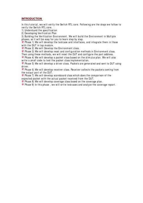
INTRODUCTIONIn this tutorial, we will verify the Switch RTL core. Following are the steps we follow to verify the Switch RTL core.1) Understand the specification2) Developing Verification Plan3) Building the Verification Environment. We will build the Environment in Multiple phases, so it will be easy for you to learn step by step.Phase 1) We will develop the testcase and interfaces, and integrate them in these with the DUT in top module.Phase 2) We will Develop the Environment class.Phase 3) We will develop reset and configuration methods in Environment class. Then using these methods, we will reset the DUT and configure the port address.Phase 4) We will develop a packet class based on the stimulus plan. We will also write a small code to test the packet class implementation.Phase 5) We will develop a driver class. Packets are generated and sent to DUT using driver.Phase 6) We will develop receiver class. Receiver collects the packets coming from the output port of the DUT.Phase 7) We will develop scoreboard class which does the comparison of the expected packet with the actual packet received from the DUT.Phase 8) We will develop coverage class based on the coverage plan.Phase 9) In this phase , we will write testcases and analyze the coverage report.SPECIFICATIONSwitch Specification:where the packet is driven out.Packet Format:Packet contains 3 parts. They are header, data and frame check sequence.Packet width is 8 bits and the length of the packet can be between 4 bytes to 259 bytes.Packet Header:Packet header contains three fields DA, SA and length.DA: Destination address of the packet is of 8 bits. The switch drives the packet to respective ports based on this destination address of the packets. Each output port has 8-bit unique port address. If the destination address of the packet matches the port address, then switch drives the packet to the output port.SA: Source address of the packet from where it originate. It is 8 bits.Length: Length of the data is of 8 bits and from 0 to 255. Length is measured in terms of bytes.If Length = 0, it means data length is 0 bytesIf Length = 1, it means data length is 1 bytesIf Length = 2, it means data length is 2 bytesIf Length = 255, it means data length is 255 bytesData: Data should be in terms of bytes and can take anything.FCS: Frame check sequenceThis field contains the security check of the packet. It is calculated over the header and data.Configuration:Switch has four output ports. These output ports address have to be configured to a unique address. Switch matches the DA field of the packet with this configured port address and sends the packet on to that port. Switch contains a memory. This memory has 4 locations, each can store 8 bits. To configure the switch port address, memory write operation has to be done using memory interface. Memory address (0,1,2,3) contains the address of port(0,1,2,3) respectively.Interface Specification:The Switch has one input Interface, from where the packet enters and 4 output interfaces from where the packet comes out and one memory interface, through the port address can be configured. Switch also has a clock and asynchronous reset signal.Memory Interface:Through memory interfaced output port address are configured. It accepts 8 bit data to be written to memory. It has 8 bit address inputs. Address 0,1,2,3 contains the address of the port 0,1,2,3 respectively.There are 4 input signals to memory interface. They areinput mem_en;input mem_rd_wr;input[1:0] mem_add;input[7:0] mem_data;All the signals are active high and are synchronous to the positive edge of clock signal. To configure a port address,1. Assert the mem_en signal.2. Asser the mem_rd_wr signal.3. Drive the port number (0 or 1 or 2 or 3) on the mem_add signal4. Drive the 8 bit port address on to mem_data signal.Input PortPackets are sent into the switch using input port.All the signals are active high and are synchronous to the positive edge of clock signal. input port has 2input signals. They areinput[7:0]data;input data_status;To send the packet in to switch,1. Assert the data_status signal.2. Send the packet on the data signal byte by byte.3. After sending all the data bytes, deassert the data_status signal.4. There should be at least 3 clock cycles difference between packets.Output Portport_* signal after one clock cycle.VERIFICATION PLANOverviewThis Document describes the Verification Plan for Switch. The Verification Plan is based on System Verilog Hardware Verification Language. The methodology used for Verification is Constraint random coverage driven verification.Feature ExtractionThis section contains list of all the features to be verified.1)ID: ConfigurationDescription: Configure all the 4 port address with unique values.2)ID: Packet DADescription: DA field of packet should be any of the port address. All the 4 port address should be used.3)ID : Packet payloadDescription: Length can be from 0 to 255. Send packets with all the lengths.4)ID: LengthDescription:Length field contains length of the payload.Send Packet with correct length field and incorrect length fields.5)ID: FCSDescription:Good FCS: Send packet with good FCS.Bad FCS: Send packet with corrupted FCS.Stimulus Generation Plan1) Packet DA: Generate packet DA with the configured address.2) Payload length: generate payload length ranging from 2 to 255.3) Correct or Incorrect Length field.4) Generate good and bad FCS.Coverage Plan1) Cover all the port address configurations.2) Cover all the packet lengths.3) Cover all correct and incorrect length fields.4) Cover good and bad FCS.5) Cover all the above combinations.Verification EnvironmentPHASE 1 TOPIn phase 1,1) We will write SystemVerilog Interfaces for input port, output port and memory port.2) We will write Top module where testcase and DUT instances are done.3) DUT and TestBench interfaces are connected in top module.4) Clock is generator in top module.NOTE: In every file you will see the syntax`ifndef GUARD_*`endif GUARD_*InterfacesIn the interface.sv file, declare the 3 interfaces in the following way.All the interfaces has clock as input.All the signals in interface are logic type.All the signals are synchronized to clock except reset in clocking block.Signal directional w.r.t TestBench is specified with modport.`ifndef GUARD_INTERFACE`define GUARD_INTERFACE//////////////////////////////////////////// Interface declaration for the memory/////////////////////////////////////////////interface mem_interface(input bit clock);logic[7:0] mem_data;logic[1:0] mem_add;logic mem_en;logic mem_rd_wr;clocking cb@(posedge clock);default input#1output#1;output mem_data;output mem_add;output mem_en;output mem_rd_wr;endclockingmodport MEM(clocking cb,input clock);endinterface////////////////////////////////////////////// Interface for the input side of switch.//// Reset signal is also passed hear. ////////////////////////////////////////////// interface input_interface(input bit clock);logic data_status;logic[7:0] data_in;logic reset;clocking cb@(posedge clock);default input#1output#1;output data_status;output data_in;endclockingmodport IP(clocking cb,output reset,input clock); endinterface///////////////////////////////////////////////// // Interface for the output side of the switch.//// output_interface is for only one output port/////////////////////////////////////////////////// interface output_interface(input bit clock);logic[7:0] data_out;logic ready;logic read;clocking cb@(posedge clock);default input#1output#1;input data_out;input ready;output read;endclockingmodport OP(clocking cb,input clock);endinterface//////////////////////////////////////////////////`endifTestcaseTestcase is a program block which provides an entry point for the test and creates a scope that encapsulates program-wide data. Currently this is an empty testcase which just ends the simulation after 100 time units. Program block contains all the above declared interfaces as arguments. This testcase has initial and final blocks.`ifndef GUARD_TESTCASE`define GUARD_TESTCASEprogram testcase(mem_interface.MEM mem_intf,input_interface.IP input_intf,output_i nterface.OP output_intf[4]);initialbegin$display(" ******************* Start of testcase ****************");#1000;endfinal$display(" ******************** End of testcase *****************");endprogram`endifTop ModuleThe modules that are included in the source text but are not instantiated are called top modules. This module is the highest scope of modules. Generally this module is named as "top" and referenced as "top module". Module name can be anything.Do the following in the top module:1)Generate the clock signal.bit Clock;initialforever#10 Clock =~Clock;2)Do the instances of memory interface.mem_interface mem_intf(Clock);3)Do the instances of input interface.input_interface input_intf(Clock);4)There are 4 output ports. So do 4 instances of output_interface.output_interface output_intf[4](Clock);5)Do the instance of testcase and pass all the above declared interfaces.testcase TC(mem_intf,input_intf,output_intf);6)Do the instance of DUT.switch DUT7)Connect all the interfaces and DUT. The design which we have taken is in verilog. So Verilog DUT instance is connected signal by signal.switch DUT(.clk(Clock),.reset(input_intf.reset),.data_status(input_intf.data_status),.data(input_intf.data_in),.port0(output_intf[0].data_out),.port1(output_intf[1].data_out),.port2(output_intf[2].data_out),.port3(output_intf[3].data_out),.ready_0(output_intf[0].ready),.ready_1(output_intf[1].ready),.ready_2(output_intf[2].ready),.ready_3(output_intf[3].ready),.read_0(output_intf[0].read),.read_1(output_intf[1].read),.read_2(output_intf[2].read),.read_3(output_intf[3].read),.mem_en(mem_intf.mem_en),.mem_rd_wr(mem_intf.mem_rd_wr),.mem_add(mem_intf.mem_add),.mem_data(mem_intf.mem_data));Top Module Source Code:`ifndef GUARD_TOP`define GUARD_TOPmodule top();///////////////////////////////////////////////////// // Clock Declaration and Generation /////////////////////////////////////////////////////// bit Clock;initialforever#10 Clock =~Clock;///////////////////////////////////////////////////// // Memory interface instance /////////////////////////////////////////////////////// mem_interface mem_intf(Clock);///////////////////////////////////////////////////// // Input interface instance /////////////////////////////////////////////////////// input_interface input_intf(Clock);///////////////////////////////////////////////////// // output interface instance /////////////////////////////////////////////////////// output_interface output_intf[4](Clock);///////////////////////////////////////////////////// // Program block Testcase instance /////////////////////////////////////////////////////// testcase TC(mem_intf,input_intf,output_intf);///////////////////////////////////////////////////// // DUT instance and signal connection ///////////////////////////////////////////////////////switch DUT(.clk(Clock),.reset(input_intf.reset),.data_status(input_intf.data_status),.data(input_intf.data_in),.port0(output_intf[0].data_out),.port1(output_intf[1].data_out),.port2(output_intf[2].data_out),.port3(output_intf[3].data_out),.ready_0(output_intf[0].ready),.ready_1(output_intf[1].ready),.ready_2(output_intf[2].ready),.ready_3(output_intf[3].ready),.read_0(output_intf[0].read),.read_1(output_intf[1].read),.read_2(output_intf[2].read),.read_3(output_intf[3].read),.mem_en(mem_intf.mem_en),.mem_rd_wr(mem_intf.mem_rd_wr), .mem_add(mem_intf.mem_add),.mem_data(mem_intf.mem_data)); endmodule`endif(S)Run the simulation:PHASE 2 ENVIRONMENTIn this phase, we will writeEnvironment class.Virtual interface declaration.Defining Environment class constructor.Defining required methods for execution. Currently these methods will not be implemented in this phase.All the above are done in Environment.sv file.We will write a testcase using the above define environment class in testcase.sv file.Environment Class:The class is a base class used to implement verification environments. Testcase contains the instance of the environment class and has access to all the public declaration of environment class.All methods are declared as virtual methods. In environment class, we will formalize the simulation steps using virtual methods. The methods are used to control the execution of the simulation.Following are the methods which are going to be defined in environment class.1) new() : In constructor method, we will connect the virtual interfaces which are passed as argument to the virtual interfaces to those which are declared in environment class.2) build(): In this method , all the objects like driver, monitor etc are constructed. Currently this method is empty as we did not develop any other component.3) reset(): in this method we will reset the DUT.4) cfg_dut(): In this method, we will configure the DUT output port address.5) start(): in this method, we will call the methods which are declared in the othercomponents like driver and monitor.6) wait_for_end(): this method is used to wait for the end of the simulation. Waits until all the required operations in other components are done.7) report(): This method is used to print the TestPass and TestFail status of the simulation, based on the error count..8) run(): This method calls all the above declared methods in a sequence order. The testcase calls this method, to start the simulation.We are not implementing build(), reset(), cfg_dut() , strat() and report() methods in this phase.Connecting the virtual interfaces of Environment class to the physical interfaces of top module.Verification environment contains the declarations of the virtual interfaces. Virtual interfaces are just a handles(like pointers). When a virtual interface is declared, it only creats a handle. It doesnot creat a real interface.Constructor method should be declared with virtual interface as arguments, so that when the object is created in testcase, new() method can pass the interfaces in to environment class where they are assigned to the local virtual interface handle. With this, the Environment class virtual interfaces are pointed to the physical interfaces which are declared in the top module.Declare virtual interfaces in Environment class.virtual mem_interface.MEM mem_intf ;virtual input_interface.IP input_intf ;virtual output_interface.OP output_intf[4];The construction of Environment class is declared with virtual interface as arguments.function new(virtual mem_interface.MEM mem_intf_new ,virtual input_interface.IP input_intf_new ,virtual output_interface.OP output_intf_new[4]);In constructor methods, the interfaces which are arguments are connected to the virtual interfaces of environment class.this.mem_intf = mem_intf_new ;this.input_intf = input_intf_new ;this.output_intf = output_intf_new ;Run :The run() method is called from the testcase to start the simulation. run() method calls all the methods which are defined in the Environment class.task run();$display(" %0d : Environment : start of run() method",$time); build();reset();cfg_dut();start();wait_for_end();report();$display(" %0d : Environment : end of run() method",$time); endtask: runEnvironment Class Source Code:`ifndef GUARD_ENV`define GUARD_ENVclass Environment ;virtual mem_interface.MEM mem_intf ;virtual input_interface.IP input_intf ;virtual output_interface.OP output_intf[4];function new(virtual mem_interface.MEM mem_intf_new ,virtual input_interface.IP input_intf_new ,virtual output_interface.OP output_intf_new[4]);this.mem_intf = mem_intf_new ;this.input_intf = input_intf_new ;this.output_intf = output_intf_new ;$display(" %0d : Environment : created env object",$time); endfunction:newfunction void build();$display(" %0d : Environment : start of build() method",$time); $display(" %0d : Environment : end of build() method",$time); endfunction:buildtask reset();$display(" %0d : Environment : start of reset() method",$time); $display(" %0d : Environment : end of reset() method",$time); endtask: resettask cfg_dut();$display(" %0d : Environment : start of cfg_dut() method",$time); $display(" %0d : Environment : end of cfg_dut() method",$time); endtask: cfg_duttask start();$display(" %0d : Environment : start of start() method",$time); $display(" %0d : Environment : end of start() method",$time); endtask:starttask wait_for_end();$display(" %0d : Environment : start of wait_for_end() method",$time); $display(" %0d : Environment : end of wait_for_end() method",$time); endtask: wait_for_endtask run();$display(" %0d : Environment : start of run() method",$time);build();reset();cfg_dut();start();wait_for_end();report();$display(" %0d : Environment : end of run() method",$time);endtask: runtask report();endtask: reportendclass`endifWe will create a file Global.sv for global requirement. In this file, define all the port address as macros in this file. Define a variable error as integer to keep track the number of errors occurred during the simulation.`ifndef GUARD_GLOBALS`define GUARD_GLOBALS`define P08'h00`define P18'h11`define P28'h22`define P38'h33int error =0;int num_of_pkts =10;`endifNow we will update the testcase. Take an instance of the Environment class and call the run method of the Environment class.`ifndef GUARD_TESTCASE`define GUARD_TESTCASEprogram testcase(mem_interface.MEM mem_intf,input_interface.IP input_intf,output_interface.OP output_intf[4]);Environment env;initialbegin$display(" ******************* Start of testcase ****************");env =new(mem_intf,input_intf,output_intf);env.run();#1000;endfinal$display(" ******************** End of testcase *****************");endprogram`endif(S)Run the simulation:(S)Log report after the simulation:******************* Start of testcase ****************0 : Environemnt : created env object0 : Environemnt : start of run() method0 : Environemnt : start of build() method0 : Environemnt : end of build() method0 : Environemnt : start of reset() method0 : Environemnt : end of reset() method0 : Environemnt : start of cfg_dut() method0 : Environemnt : end of cfg_dut() method0 : Environemnt : start of start() method0 : Environemnt : end of start() method0 : Environemnt : start of wait_for_end() method 0 : Environemnt : end of wait_for_end() method 0 : Environemnt : end of run() method******************** End of testcase *****************PHASE 3 RESETIn this phase we will reset and configure the DUT.The Environment class has reset() method which contains the logic to reset the DUT and cfg_dut() method which contains the logic to configure the DUT port address.NOTE: Clocking block signals can be driven only using a non-blocking assignment.Define the reset() method.1) Set all the DUT input signals to a known state.mem_intf.cb.mem_data <=0;mem_intf.cb.mem_add <=0;mem_intf.cb.mem_en <=0;mem_intf.cb.mem_rd_wr <=0;input_intf.cb.data_in <=0;input_intf.cb.data_status <=0;output_intf[0].cb.read <=0;output_intf[1].cb.read <=0;output_intf[2].cb.read <=0;output_intf[3].cb.read <=0;2) Reset the DUT.// Reset the DUTinput_intf.reset <=1;repeat(4)@ input_intf.clock;input_intf.reset <=0;3) Updated the cfg_dut method.task cfg_dut();$display(" %0d : Environment : start of cfg_dut() method",$time);mem_intf.cb.mem_en <=1;@(posedge mem_intf.clock);mem_intf.cb.mem_rd_wr <=1;@(posedge mem_intf.clock);mem_intf.cb.mem_add <=8'h0;mem_intf.cb.mem_data <=`P0;$display(" %0d : Environment : Port 0 Address %h ",$time,`P0);@(posedge mem_intf.clock);mem_intf.cb.mem_add <=8'h1;mem_intf.cb.mem_data <=`P1;$display(" %0d : Environment : Port 1 Address %h ",$time,`P1);@(posedge mem_intf.clock);mem_intf.cb.mem_add <=8'h2;mem_intf.cb.mem_data <=`P2;$display(" %0d : Environment : Port 2 Address %h ",$time,`P2);@(posedge mem_intf.clock);mem_intf.cb.mem_add <=8'h3;mem_intf.cb.mem_data <=`P3;$display(" %0d : Environment : Port 3 Address %h ",$time,`P3);@(posedge mem_intf.clock);mem_intf.cb.mem_en <=0;mem_intf.cb.mem_rd_wr <=0;mem_intf.cb.mem_add <=0;mem_intf.cb.mem_data <=0;$display(" %0d : Environment : end of cfg_dut() method",$time); endtask: cfg_dut(4) In wait_for_end method, wait for some clock cycles.task wait_for_end();$display(" %0d : Environment : start of wait_for_end() method",$time); repeat(10000)@(input_intf.clock);$display(" %0d : Environment : end of wait_for_end() method",$time); endtask: wait_for_end(S)Run the simulation:(S)Log File report******************* Start of testcase ****************0 : Environment : created env object0 : Environment : start of run() method0 : Environment : start of build() method0 : Environment : end of build() method0 : Environment : start of reset() method40 : Environment : end of reset() method40 : Environment : start of cfg_dut() method70 : Environment : Port 0 Address 0090 : Environment : Port 1 Address 11110 : Environment : Port 2 Address 22130 : Environment : Port 3 Address 33150 : Environment : end of cfg_dut() method150 : Environment : start of start() method150 : Environment : end of start() method150 : Environment : start of wait_for_end() method100150 : Environment : end of wait_for_end() method100150 : Environment : end of run() method******************** End of testcase *****************PHASE 4 PACKETIn this Phase, We will define a packet and then test it whether it is generating as expected.Packet is modeled using class. Packet class should be able to generate all possible packet types randomly. Packet class should also implement required methods like packing(), unpacking(), compare() and display() methods.We will write the packet class in packet.sv file. Packet class variables and constraints have been derived from stimulus generation plan.Revisit Stimulus Generation Plan1) Packet DA: Generate packet DA with the configured address.2) Payload length: generate payload length ranging from 2 to 255.3) Correct or Incorrect Length field.4) Generate good and bad FCS.1) Declare FCS types as enumerated data types. Name members as GOOD_FCS and BAD_FCS.typedef enum{GOOD_FCS,BAD_FCS} fcs_kind_t;2) Declare the length type as enumerated data type. Name members as GOOD_LENGTH and BAD_LENGTH.typedef enum{GOOD_LENGTH,BAD_LENGTH} length_kind_t;3) Declare the length type and fcs type variables as rand.rand fcs_kind_t fcs_kind;rand length_kind_t length_kind;4) Declare the packet field as rand. All fields are bit data types. All fields are 8 bit packet array. Declare the payload as dynamic array.rand bit[7:0] length;rand bit[7:0] da;rand bit[7:0] sa;rand byte data[];//Payload using Dynamic array,size is generated on the flyrand byte fcs;5) Constraint the DA field to be any one of the configured address.constraint address_c { da inside{`P0,`P1,`P2,`P3};}6) Constrain the payload dynamic array size to between 1 to 255.constraint payload_size_c {data.size inside{[1:255]};}7) Constrain the payload length to the length field based on the length type.constraint length_kind_c {(length_kind ==GOOD_LENGTH)-> length ==data.size;(length_kind ==BAD_LENGTH)-> length ==data.size+2;}Use solve before to direct the randomization to generate first the payload dynamic array size and then randomize length field.constraint solve_size_length {solve data.size before length;}8) Constrain the FCS field initial value based on the fcs kind field.constraint fcs_kind_c {(fcs_kind ==GOOD_FCS)-> fcs ==8'b0;(fcs_kind ==BAD_FCS)-> fcs ==8'b1;}9) Define the FCS method.function byte cal_fcs;integer i;byte result ;result =0;result = result ^ da;result = result ^ sa;result = result ^ length;for(i =0;i<data.size;i++)result = result ^data[i];result = fcs ^ result;return result;endfunction: cal_fcs10) Define display methods:Display method displays the current value of the packet fields to standard output.virtual function void display();$display("\n---------------------- PACKET KIND ------------------------- ");$display(" fcs_kind : %s ",fcs_());$display(" length_kind : %s ",length_());$display("-------- PACKET ---------- ");$display(" 0 : %h ",da);$display(" 1 : %h ",sa);$display(" 2 : %h ",length);foreach(data[i])$write("%3d : %0h ",i +3,data[i]);$display("\n %2d : %h ",data.size()+3, cal_fcs);$display("----------------------------------------------------------- \n");endfunction: display11) Define pack method:Packing is commonly used to convert the high level data to low level data that can be applied to DUT. In packet class various fields are generated. Required fields are concatenated to form a stream of bytes which can be driven conveniently to DUTinterface by the driver.virtual function int unsigned byte_pack(ref logic[7:0] bytes[]);bytes =new[data.size+4];bytes[0]= da;bytes[1]= sa;bytes[2]= length;foreach(data[i])bytes[3+ i]=data[i];bytes[data.size()+3]= cal_fcs;byte_pack = bytes.size;endfunction: byte_pack12) Define unpack method:The unpack() method does exactly the opposite of pack method. Unpacking is commonly used to convert a data stream coming from DUT to high level data packet object.virtual function void byte_unpack(const ref logic[7:0] bytes[]);this.da = bytes[0];this.sa = bytes[1];this.length = bytes[2];this.fcs = bytes[bytes.size-1];this.data=new[bytes.size-4];foreach(data[i])data[i]= bytes[i +3];this.fcs =0;if(bytes[bytes.size-1]!= cal_fcs)this.fcs =1;endfunction: byte_unpack14) Define a compare method.Compares the current value of the object instance with the current value of the specified object instance.If the value is different, FALSE is returned.virtual function bit compare(packet pkt);compare=1;if(pkt ==null)begin$display(" ** ERROR ** : pkt : received a null object ");compare=0;endelsebeginif(pkt.da !==this.da)begin$display(" ** ERROR **: pkt : Da field did not match");compare=0;endif(pkt.sa !==this.sa)begin$display(" ** ERROR **: pkt : Sa field did not match");compare=0;endif(pkt.length !==this.length)begin$display(" ** ERROR **: pkt : Length field did not match");compare=0;endforeach(this.data[i])if(pkt.data[i]!==this.data[i])begin。
systemverilog类的方法SystemVerilog类的方法SystemVerilog是一种硬件描述语言,用于设计和验证数字电路。
在SystemVerilog中,类是一种重要的概念,用于组织和封装代码。
类中的方法是实现类功能的关键部分。
本文将介绍一些常见的SystemVerilog类的方法。
1. 构造函数(Constructor)构造函数是一种特殊的方法,用于在创建类的实例时初始化对象的成员变量。
它的名称与类名相同,并且没有返回类型。
构造函数可以有参数,用于传递初始化值。
例如,一个名为"myClass"的类的构造函数可以如下所示:```systemverilogclass myClass;int data;function new(int value);data = value;endfunctionendclass```在实例化类时,可以通过传递参数来调用构造函数,并初始化对象的成员变量。
```systemverilogmyClass obj = new(10);```2. 成员函数(Member Function)成员函数是定义在类中的方法,可以操作类的成员变量,并实现类的功能。
成员函数可以有返回值和参数。
例如,一个名为"add"的成员函数可以如下所示:```systemverilogclass myClass;int data;function int add(int value);data += value;return data;endfunctionendclass```在类的实例上调用成员函数时,可以使用"."运算符来访问该函数,并传递参数。
例如:```systemverilogmyClass obj;obj.add(5);```3. 静态函数(Static Function)静态函数是定义在类中的方法,不依赖于类的实例,可以直接通过类名调用。
systemverilog验证方法SystemVerilog验证方法引言在现代芯片设计中,验证是一个非常重要的环节。
SystemVerilog 是一种常用的硬件描述语言,有许多验证方法可以帮助设计人员有效验证设计的正确性。
本文将详细介绍一些常用的SystemVerilog验证方法。
1.仿真验证方法•使用仿真工具进行功能验证–利用Simulator工具来模拟设计行为以进行功能验证。
验证工程师可以编写testbench来生成输入数据,驱动设计的输出,并进行断言验证。
–通过创建各种激励来测试设计中的不同情况,包括边界情况、异常情况和极端情况等。
•波形分析验证–利用仿真工具生成波形,并分析波形来验证设计的正确性。
可以检查信号的时序关系、逻辑等,并比较期望结果和实际结果。
波形分析验证可以在不同抽象级别进行,包括电平验证、逻辑状态验证和功能验证等。
2.形式验证方法形式验证是一种使用形式工具来验证设计是否满足规范的方法。
形式工具基于设计的数学模型进行验证,可以全面而快速地验证设计的正确性。
•模型检查方法–使用形式工具对设计进行形式化建模,并使用模型检查器来验证设计是否满足特定的属性。
设计人员需要编写属性规范来描述设计的期望行为,并利用模型检查器来自动验证属性是否满足。
•定理证明方法–使用形式工具来进行数学定理的证明来验证设计的正确性。
设计人员需要将设计抽象为一个形式化的数学模型,并利用定理证明器来验证设计是否满足特定的性质。
3.边界扫描方法边界扫描方法是一种将设计周围的接口边界进行扫描以验证设计的方法。
•验证接口协议–针对设计中使用的接口协议,可以编写验证环境来验证接口协议是否正确地被设计所遵循。
验证环境可以利用随机算法生成各种接口交互情况,并验证设计的响应是否满足接口协议规定的规范。
•验证接口互连–针对设计中的各个接口之间的互连,可以编写验证环境来验证互连是否满足设计的要求。
验证环境可以生成接口交互的各种情况,并验证互连的正确性和稳定性。
SystemVerilog语言知识介绍1. 对面向对象编程(OOP)的支持:SystemVerilog引入了类和对象的概念,使得设计和验证更加模块化和可重用。
类可以包含数据成员和成员函数,可以继承和多态,从而使设计更加灵活和可扩展。
2. 接口:SystemVerilog引入了接口的概念,用于定义组件之间的通信和互连。
接口可以包含信号和方法,可以被多个模块实例化和连接在一起,从而简化了设计和验证的过程。
3. 任务和函数:SystemVerilog支持任务和函数的定义,用于执行一些特定的操作和计算。
任务是并发执行的,可以用于模拟硬件行为。
函数可以返回一个值,可以用于计算逻辑和数据处理。
4. 动态数组:SystemVerilog引入了动态数组的概念,可以在运行时动态地分配和管理内存。
这对于处理变长数据结构(如队列和堆栈)非常有用,同时也可以简化设计和验证的过程。
5. 时序建模:SystemVerilog提供了一些特性,用于描述和模拟数字系统中的时序行为。
例如,可以使用时钟、触发器和延迟来定义和控制信号的时序关系。
这使得设计和验证更加准确和可靠。
6. 断言:SystemVerilog引入了断言的概念,用于描述和验证设计的一些属性和约束。
断言可以在运行时检查设计的正确性,并在出现错误时提供错误信息。
这对于设计和验证的调试和验证非常有用。
除了以上特性,SystemVerilog还具有一些其他的功能,如并行块、并行循环、封装和配置等。
这些功能都使得SystemVerilog成为一个强大而灵活的硬件描述语言,广泛应用于数字系统的设计和验证。
总的来说,SystemVerilog是一种用于硬件设计和验证的高级硬件描述语言。
它具有面向对象编程的特性,支持接口、任务和函数,提供动态数组和时序建模等功能。
它的强大和灵活性使得它成为了工业界和学术界广泛使用的硬件描述语言之一。
uvm system verilog总结### UVM System Verilog 总结#### 导语UVM(Universal Verification Methodology)与System Verilog的结合,为芯片设计验证领域带来了革新。
这种方法论不仅提高了验证效率,还增强了验证的可重用性和覆盖率。
本文将全面总结UVM与System Verilog的相关概念、特点以及应用。
---#### 一、UVM与System Verilog概述**1.1 UVM简介**UVM是建立在System Verilog基础上的一个标准化验证方法论,旨在提供一种通用的、模块化的验证平台。
它通过将验证环境分层,实现了环境的可重用性和易于维护性。
**1.2 System Verilog简介**System Verilog是一种硬件描述和验证语言,结合了Verilog和VHDL的优点,并增加了面向对象编程的特性。
它在芯片设计和验证中广泛应用。
---#### 二、UVM的核心特点**2.1 面向对象**UVM采用面向对象的设计思想,将验证环境分为不同的类和层次,便于管理和重用。
**2.2 模块化**UVM的模块化设计使得验证环境可以根据不同的测试需求灵活组合和配置。
**2.3 自动化**UVM支持自动化测试,包括自动生成测试序列、自动检查和报告错误等。
---#### 三、System Verilog在UVM中的应用**3.1 非阻塞赋值**System Verilog的非阻塞赋值在UVM中用于描述硬件行为。
**3.2 面向对象编程**System Verilog的面向对象编程特性使得UVM可以定义基类和派生类,实现代码的复用。
**3.3 功能覆盖**利用System Verilog的功能覆盖(Functional Coverage)特性,UVM 可以全面检查设计功能的覆盖率。
---#### 四、UVM与System Verilog的结合优势**4.1 提高验证效率**UVM与System Verilog的结合使得验证人员可以快速搭建验证环境,提高验证效率。
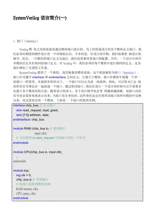
语言简介( SystemVerilog 语言简介(一)1. 接口(Interface) Verilog 模块之间的连接是通过模块端口进行的。
为了给组成设计的各个模块定义端口,我 们必须对期望的硬件设计有一个详细的认识。
不幸的是,在设计的早期,我们很难把握设计的细 节。
而且,一旦模块的端口定义完成后,我们也很难改变端口的配置。
另外,一个设计中的许多 模块往往具有相同的端口定义,在 Verilog 中,我们必须在每个模块中进行相同的定义,这为我 们增加了无谓的工作量。
SystemVerilog 提供了一个新的、高层抽象的模块连接,这个连接被称为接口(Interface)。
接口在关键字 interface 和 endinterface 之间定义,它独立于模块。
接口在模块中就像一个单一 的端口一样使用。
在最简单的形式下,一个接口可以认为是一组线网。
例如,可以将 PCI 总线的 所有信号绑定在一起组成一个接口。
通过使用接口, 我们在进行一个设计的时候可以不需要首先 建立各个模块间的互连。
随着设计的深入,各个设计细节也会变得越来越清晰,而接口内的信号 也会很容易地表示出来。
当接口发生变化时, 这些变化也会在使用该接口的所有模块中反映出来, 而无需更改每一个模块。
下面是一个接口的使用实例: interface chip_bus; // 定义接口 wire read_request, read_grant; wire [7:0] address, data; endinterface: chip_bus module RAM (chip_bus io, // 使用接口 input clk); // 可以使用 io.read_request 引用接口中的一个信号 endmodule module CPU(chip_bus io, input clk); ... endmodule module top; reg clk = 0; chip_bus a; // 实例接口 // 将接口连接到模块实例 RAM mem(a, clk); CPU cpu(a, clk); endmodule实际上,SystemVerilog 的接口不仅仅可以表示信号的绑定和互连。
一、引言在现代数字电子领域,Vivado是一种流行的集成开发环境,用于FPGA设计和综合。
SystemVerilog是一种基于Verilog的硬件描述语言,它增加了一些高级特性以支持更复杂的硬件设计。
本文将探讨在Vivado中使用SystemVerilog进行开发的步骤,以帮助读者更好地理解和掌握这一技术。
二、准备工作在开始使用Vivado和SystemVerilog进行开发之前,首先需要安装Vivado并配置好开发环境。
确保你已经安装了合适的Vivado版本,并且能够正确连接到你的FPGA开发板。
另外,也需要一定的SystemVerilog编程基础,包括对模块化设计、数据类型和并发控制等概念的理解。
三、创建工程在Vivado中创建一个新的工程,选择你的FPGA型号并确定工程保存的位置。
在创建工程的过程中,你需要设置好工程的基本信息,包括名称、版本和描述等。
在工程创建完成后,Vivado会自动生成一些默认的文件和目录结构,用于存放你的设计文件和约束文件等。
四、编写SystemVerilog代码接下来,你需要编写SystemVerilog代码来描述你的硬件设计。
可以使用Vivado内置的文本编辑器或者外部编辑器来编写代码文件,然后将代码文件添加到你的工程中。
在编写代码时,要注意遵循SystemVerilog的语法规范,并且使用模块化的设计思想来构建你的硬件模块。
五、综合和实现完成SystemVerilog代码编写后,你需要进行综合和实现操作,将代码映射到FPGA上。
在Vivado中,可以通过执行综合和实现的工具链来完成这一过程。
综合操作将把你的代码转换成逻辑门级的表示形式,而实现操作则将逻辑门映射到FPGA的逻辑资源上。
六、仿真和调试在综合和实现完成后,你可以进行仿真和调试来验证你的设计的功能和性能。
Vivado提供了强大的仿真工具,可以方便地对你的设计进行测算和调试。
通过仿真和调试,你可以发现并解决设计中的问题,保证最终的硬件设计能够正确地工作。
在Verilog中,`system`函数用于执行一个系统任务或调用一个系统函数。
它通常用于执行那些需要与外部环境交互的操作,例如读取或写入文件、与网络通信等。
`system`函数的一般语法如下:
```verilog
result = system("command");
```
其中,`command`是要执行的外部命令或系统函数。
`result`是该命令的输出结果。
下面是一个使用`system`函数执行外部命令的示例:
```verilog
module top;
initial begin
$display("Executing external command...");
result = system("ls -l"); // 执行外部命令,获取文件列表
$display("Command output: %s", result);
end
endmodule
```
在上面的示例中,`system("ls -l")`调用了外部命令`ls -l`,该命令用于列出当前目录下的文件列表。
执行结果将被存储在`result`变量中,并使用`$display`函数输出到仿真控制台。
需要注意的是,`system`函数的具体实现可能因仿真器而异。
因此,在使用`system`函数之前,建议先查看所使用的仿真器的文档以了解其支持的系统函数和命令。
SystemV erilog简介设计SystemV erilog简介★北京航空航天大学夏宇闻【l】国集成电路ChinaIntegratedCircuit摘要:美国电气和电子工程师协会(IEEE)最近(2005年11月9日)批准了SystemV erilog硬件描述语言的新标准.新标准是为了适应目益复杂的系统芯片(SoC)设计在原V erilog 一2001的基础上扩展的.按新标准开发的EDA工具必将大幅度地提高SoC的设计和验证效率.本文对新标准的扩展做了简要的介绍,希望引起国内IC设计界对这种功能强大语言的重视.月lJ吾SystemV erilog是IEEE最近推出的硬件描述和验证语言,它是在原V erilog(IEEE1364—1995和一2001)基础上扩展的新语言.这种新语言将设计和验证所需的语言组合成同一种语言.而且Sys—temV erilog还是V erilog一2001的超集.因此,目前的V erilog用户使用SystemV erilog不存在任何问题.SystemV erilog一问世就拥有大量承诺支持它的供应商,这一切都预示着SystemV erilog会有良好的市场前景.SystemV erilog与V erilog有许多重要的区别.第一,SystemV erilog提供了完整的仿真模型,它将每个时隙细分成11个有序的段,并规定了每个段内必须发生的事件.这样就可以避免当仿真包含反应性测试平台,覆盖率分析工具和相互作用的第三方c模型在内的各种模型时,有可能发生的某些不确定性.第二,SystemV erilog具有类似c++语言的一些高级数据类型和功能,如:结构体,联合体,打包和非打包的数组,动态存储器分配和动态进程等,更适合测试平台的开发和系统级建模.第三,仿真和静态验证工具可以使用相同的声明集合.第四,Sys—temV erilog的新扩充还包括了接口块,断言函数等. 这些扩展使得SystemV erilog可以在更高的抽象层次上,更方便地为复杂IP之间的连接,测试验证和查错建立模型,显着地提高了代码的可读性,可维护性,设计和验证效率,极大地提高了编写测试平台的能力.SystemV erilog由OVI(OpenV erilogInternation—a1)和VI(VHDLInternatioan1)两个国际标准化组织合作成立的Accellera集团推出,主要用于数字系统芯片的设计和验证流程.由于SystemV eHlog具有与高级编程语言(如C语言)直接连接调试的强大功能,为系统级软硬件协同设计验证提供了极大的方便,因此对包括软硬件在内的现代复杂SoC设计有非常深远的意义.读者若想全面深入地理解和掌握语法的要点,不但需要认真阅读SystemV erilogLRM(语法手册), 还需要上机练习才行.为了帮助读者用最少的时间初步了解SystemV erilog标准所做的扩展,作者将从下面30个方面,对最近批准的SystemV erilog标准作简要的介绍.1)数组在V erilog中可以声明数组类型,reg和线网类型还可以具有矢量位宽.在对象名前面声明的位宽表示变量的位宽,在对象名后面声明的维数表示数编者注:IEEE刚刚于2005年11月9日批准SystemV erilog硬件描述语言的新标准之际,夏宇闻老师为我刊编写了本文.具体介绍了这一标准语言,相信一定能受到广大设计人员,尤其是SOC设计人员的欢迎.r笛R1蝴,_曩岛程曩曩■~,.…..一……由国集成电路ChinaIntegratedCircuit组的个数.举例如下:reg[7:O】rl[1:256】;//声明rl为256个8位的变量在Systemverilog中设计者可使用不同的术语表示数组:使用"打包数组(packedarray)"这一术语表示在对象名前面声明的数组的维数;使用"非打包数组(unpackedarray)"这一术语表示在对象名后面声明的数组的维数.打包数组可以由下面的数据类型组成:bit,logic,reg,wire以及其它的线网类型.无论是打包数组还是非打包数组都可以声明成多维的.举例如下:bit[7:0】a;//打包数组a为bit类型(双值)只有一个包(包由字节,即8位,组成)bitb[7:O】;//非打包数组b为bit类型(双值)(一位),共有8位从b[O】到b[7】bjt[0:11][7:0卜;//打包数组c(每包12个字节),只有一个包bit[3:0】【7:0】d[1:1O】;//d的每个包由4个字节(8位)组成,d共有l0个非打包的包上例中非打包数组大小的定义([1:10】)放在打包数组(d)定义之后,这就允许将整个打包数组(4个字节)作为单一的元素进行引用.在上面的例子中,d[1】引用非打包数组的第一个元素,该元素由4 个字节组成.2)枚举类型V erilog~法中没有枚举类型.标识符必须显式地声明为线网,变量或参数,并赋值.SystemV erilog 允许使用类似于C的语法定义枚举类型.枚举类型具有一组被命名的初始值.缺省情况下,初始值从0 开始递增,但是设计者也可以显式地指定初始值. 枚举类型的例子如下:enum{red,yellow,green}RGB;//red=2'b0,yellow=2'b01.green=2'blO;enum{W AIT=2'b01,LOAD,DONE}states;//LOAD=2'bl0.DONE=2'bl1:设计者还可以使用typedef为枚举类型指定一个名字,从而允许这个枚举类型可以在许多地方使hHn.Ij,^^?^IIr,tmr-r,^m设计用.例如:typedefenum{FALSE=I'b0,TRUE}boolean; booleanready;booleantest——complete;3)结构体和联合体V erilog语法中没有结构体或联合体,而结构体或联合体在把几个声明组合在一起的时候非常有用. SystemV erilog增加了结构体和联合体,其语法类似于C.struct{reg[15:0】opcode;reg[23:0】addr;}IR;//声明IR是一个结构体,由两部分组成:16位的操作码opcode和24位的地址addrunion{intI:shortrealf=}N;结构体或联合体中的域可以通过在变量名和域名字之间插入句点()来引用:IR.opcode=1;//设置IR变量中的opcode域N.f=O.O;//将N变量中的f域设置成浮点数的值O.O设计者可以使用typedef为结构体或联合体的定义指定名字,举例如下.typedefstruct{reg[7:0】opcode;reg[23:0】addr;}instruction;//命名的结构体,instruction是一个由两部分//(16位的操作码opcode和24位的地址addr)组成的指令instructionIR://结构体实例,定义IR具有指令(instruction)同样的结构结构体可以使用值的级联来完整地赋值,例如:instruction={5,200];//表示操作码为5,地址为200 结构体可以作为整体传递到函数或任务,也可以从函数或任务传递过来,也可以作为模块端口进行传递.4)接口(Interface)V erilog模块之间的连接是通过模块端口进行的.为了给构成设计的各个模块定义端口,设计者必须对所做的硬件设计有详细的认识.但在设计的初期,设计者很难把握设计的细节.而一旦模块的端口定义完成后,端口的配置就很难改变.另外, 设计中的许多模块往往具有相同的端口名,在V er—ilog语言中,设计者必须对每个模块进行相同的定义和连接,这增加许多无谓的工作量.SystemV erilog提供了一个全新的,高层抽象的连接定义块,这个连接块被称为接口(Interface).接口块在关键字interface和endinterface之间定义,它独立于模块.接口在模块中就像独立端口一样使用. 在最简单的形式下,接口可以认为是一组线网.例如,可以将PCI总线的所有信号绑定在一起组成一个接口.借助于接口块的定义,编写代码时若遇到许多个实例互相连接的情况,可以不必逐一建立各模块对应端口间的连接,大大加快了设计工作.随着设计的深入,设计细节逐渐变得清晰,许多模块的接口需要添加和修改.而对接口块所做的修改,可在使用该接口块的每个模块中反映出来,而无需逐个修改每个模块的接口,大大节省了相关模块接口修改的工作量.下面是接口的使用实例: interfacechip—bus;//定义接口chip—bus wireread_request,read_grant;wire【7:0】address,data;endinterfacemoduleRAM(chip—busio,//RAM模块的端口中包含已定义的接口chip—bus,具体接口名为io inputclk);//可以使用io.read—request引用接口中的一个信号endmodU1emoduleCPU(chip——busio,inputclk);//CPU模块的端口中也使用了已定义的接口chip—bus,具体名为iomoduletop;regclk=0:chip—busa;//接口的实例引用,说明a是与chip—bus同样的接口RAMmem(.io(a),clk);//将接口a连接到mem实例模块的io接口CPUcpu(.io(a),clk);//将接口a连接到cpu实例模块的io接口endmodule实际上,SystemV erilog的接口不仅仅可以表示信号的绑定和互连.由于SystemV erilog的接口中可以包含参数,常量,变量,结构,函数,任务,initial块, always块以及连续赋值语句,所以SystemVerilog的接口还可以包含内建的协议检查,以及使用该接口的每个模块共用的功能.5)随机激励信号的产生在设计中,总是有一些边角情况是比较不容易发生,或是不容易想到的,因此借助随机产生的测试激励,可以帮助验证边角情况.V erilog已经具有$random来产生随机数,但设计者并无有效办法控制该随机数的范围与顺序.在SystemV erilog3.1里, 增加了rand与randc两个对象类,用于设定随机数产生的条件.下例中设计者声明一个名为Bus的类, 并规定地址总线的最低的两位必须为0.而在使用时,利用rand类里的randomize子类,产生50个随机数据与地址,大大简化了V erilog原来产生随机数的手段.classBus;randbit[15:0】addr;randbit[31:0】data;constraintword_align{addr[1:0】=='2b0;} endclassrepeat(50)beginif(bus.randomize0==1)$displayfIIaddr=%16hdata=%hha",bus.addr,bus.data);else$display("Randomizationfailed.\n");end6)时间单位和精度在V erilog中,表示时间的值使用一个数来表示,而不带有任何时间单位.例如:forever#5clock=~clock;单从这一语句中,设计者无法判断5代表的是5ns?5ps?还是5us.V erilog的时间单位和精度是作为每个模块的属性,在模块代码前用编译器指令,timescale来设置.使用这种方法存在固有的缺陷, 因为编译器指令的执行依赖于源代码的编译顺序, 编译器总是将它遇到的最后一个,timescale设置的时间单位和精度作为标准.那么,若有些模块代码没有用,timescale设置时间单位和精度,当这种源代码前缺少时间单位定义的模块与有,timescale设置的模块一起仿真时,就有可能出现完全想象不到的结果.●,●●^.Ih…^…i……一SystemV erilog为了能更方便地控制时间单位,做了两个重要的改进.1)时间值可以显式地指定为某一个单位.时间单位可以在S,ms,ns,ps或fs之间选择,时间单位作为时间值的后缀出现.例如: forever#5nsclock=~clock;2)SystemV erilog允许使用新的关键字(timeu—nits和timeprecision)来指定时间单位和精度.这些声明可以在任何模块中指定,同时也可以在全局空间中指定.时间单位和精度必须是10的幂,范围可以从S到fs.例如:timeunits1ns;timeprecision10ps;7)抽象数据类型V erilog提供了面向底层硬件的线网,寄存器和变量数据类型.这些类型代表了4态逻辑值,通常用来在底层J二对硬件进行建模和验证.线网数据类型还具有多个强度级别,并且能够为多驱动源的线网提供解析功能.SystemV erilog包括了C语言的char和int数据类型,它允许在V erilog模型和验证程序中直接使用c和c++代码.V erilogPLI不再需要整合总线功能模型,算法模型和C函数.SystemVerilog还为V er—ilog加入了几个新的数据类型,以便能够在更抽象的层次上为硬件电路建模.char:两态的有符号变量,它与C语言中的char数据类型相同,可以是一个8位整数(ASCII)或shortint(Unicode):int:两态的有符号变量,它与C语言中的int数据类型相似,但被精确地定义成32位; shortint:两态的有符号变量,被精确地定义成l6位;longint:两态的有符号变量,它与C语言中的long数据类型相似,但被精确地定义成64位; byte:两态的有符号变量,被精确地定义成8位;bit:两态的可以具有任意位宽的无符号数据类型,可以用来替代V erilog的reg数据类型; logic:四态的可以具有任意位宽的无符号数据类型,可以用来替代V erilog的线网或reg数据类型,但具有某些限制;shortreal:两态的单精度浮点变量,与C语言的float类型相同;void:表示没有返回值,可以定义成函数的返回值,与C语言中的含义相同.SystemV erilog的bit和其他数据类型允许用户使用两态逻辑为设计建模,两态逻辑模型的仿真速度快,效率高.由于V erilog语言没有两态数据类型, 因此许多仿真器将这种功能作为仿真器的选项.有些仿真器不支持两态逻辑数据,所以有时在必须用三态或四态逻辑建模的设计中强制使用两态逻辑, 仿真器还会出现问题.而SystemV erilog的bit数据类型能够极大提高仿真器的性能,同时在需要的时候仍然可以使用三态或四态逻辑.用改变数据类型的方法来代替仿真器的逻辑状态选项,使得设计模型能适应多种仿真器.SystemV erilog的logic数据类型比V erilog的线网和寄存器数据类型更加灵活,它使得在任何抽象层次上为硬件建模变得更加容易.logic类型能够以下面的任何一种方法赋值:任意次的过程赋值语句赋值,能够替代V erilog的reg类型;单一的连续赋值语句赋值,能够有限地替代V erilog的wire类型;连接到单一原语的输出,能够有限制地替代V erilog的wire类型;由于logic数据类型能够被用来替代V erilog的reg或wire(具有限制),这就使得设计者能在更高的抽象层次上建模,并且随着设计的深人,能不断地添加设计细节而不必改变数据类型的声明.logic数据类型不能表示信号的强度,也不具有线逻辑的解析功能,因此logic数据类型比V erilog的wire类型能更有效地仿真和综合.8)有符号和无符号限定符缺省情况下,V erilog的net和reg数据类型是无符号类型,integer类型是有符号类型变量.V er—ilog一2001标准允许使用signed关键字将无符号类型显式地声明成有符号类型.SystemV erilog添加了类似的能力,它可以通过unsigned关键字将有符号数据类型显式地声明成有无符号数据类型.例如:值得注意的是unsigned在V erilog中是保留字,但并没有被V erilog标准使用.9)用户定义的类型V erilog不允许用户定义新的数据类型.Sys—temV erilog通过使用typedef提供了定义新的数据类型方法,这与C语言类似.用户定义的类型可以与其它数据类型一样地在声明中使用.例如: typedefunsignedintuint;uinta.h:用户定义的数据类型可以在它的定义之前使用,只要它首先在空的typedef中说明,例如: typedefint48;//空的typedef,即虽然定义了int48,但究竟int48定义成什么?//还需要在其他地方进行完整的定义int48c;//虽然int48具体如何定义并未确定,但可以把c定义为是int48类型的.10)在命名块中声明变量V erilog允许变量在命名的begin—end或fork—join语句组中声明.对于命名的语句组来说,在块内定义的变量是本地的,但它们可以用层次化命名方法引用它们.在SystemV erilog中,变量既可以在命名的块中也可以在未命名的块中声明,对在未命名的块中声明的变量,不能使用层次名来访问,所有的变量类型,包括用户定义的类型,枚举类型,结…IIII【l】国集成电路斗』■ChinaIntegratedCircuit构体和联合体都可以在begin—end或fork-join命名的语句组中声明.11)常量在V erilog中有三种特殊类型的常量:parame—ter,specparam和localparam.而在SystemV erilog中, 允许使用const关键字声明常量.例如: constcharcolon=":":12)可重定义的数据类型SystemV erilog扩展了V erilog的参数(parame—ter)功能,使其可以包含数据类型.若模块定义了参数,用于表示数据类型,则在引用该模块的实例时,可通过参数传递重新定义每个实例中的数据类型. 例如:modulefoo;#(parametertypeVAR—TYPE=shortint;). (inputlogic[7:0】i,outputlogic[7:0】o);V AR_TYPEJ=0;//如果不重新定义,j的数据类型为shortintmodulebar;logic[3:0】i,o;foo#(.VAR_TYPE(int))ul(i,o);//重新将V AR—TYPE定义成int类型endmodule13)模块端口连接在V erilog中,可以连接到模块端口的数据类型被限制为线网类型以及变量类型中的reg,integer和time.而在SystemVerilog中,则去除了这种限制,任何数据类型都可以通过端口传递,包括实数,数组和结构体.14)用字母赋值ht}n.IhAAAAA!,,im,1,,n在V erilog中,用字母赋值时候有一些约定.而SystemV erilog则为用字母赋值作了下面的改进:变量的所有位可以方便地用字母(,0,,1,,z或,X)赋值.填充一个任意位宽的矢量,而无需显式地指定矢量的位宽,例如:bit【63:0]data;data=,1;//将data的所有位(共64位)都设置成1 15)字符串(string)SystemV erilog添加了可变长度的字符串数据类型,使用者不需声明字符串数据的长度,编译工具会自动判断.而SystemV erilog也提供了常用字符串处理函数,例如putcO,getc0,atoi0,itoa0等,而口些字符串处理函数功能以前必须通过PLI函数才能实现.16)强制类型转换V erilog不能将一个值强制转换成不同的数据类型.SystemV erilog通过使用<数据类型>'操作符提供了数据类型的强制转换功能.这种强制转换可以转换成任意类型,包括用户定义的类型.例如:int'(2.03.0)//将计算结果转换为int类型m~ype'(foo)//将转换为m~ype类型在强制转换操作符前指定一个10进制数可以用来确定转换后的矢量位宽,例如:17'(x一2)∥将结果转换为17位宽也可以将结果转换成有符号值,例如:signed'(x)//将x转换为有符号值17)操作符V erilog没有C语言的递增(++)和递减(一)操作符.而SystemV erilog加人了几个新的操作符:++和~:递增和递减操作符;+=,一=,术=,/=,%=,&=,=,I=,<<=,>>=,<<<= 和>>>=赋值操作符;18)具有唯一性和优先级的条件语句在V erilog中,如果没有遵循严格的编码风格,它的if-else和case语句会在RTL仿真和RTL综合间具有不一致的结果.如果没有正确使用full_case和parallel—case综合指令还会引起一些其它的错误.SystemV erilog~够显式地指明什么时候条件语句的分支是唯一的,或者什么时候需要计算优先级. 设计者可以在if或case关键字之前使用unique或requires关键字.这些关键字可以向仿真器,综合编译器,以及其它工具指示设计者期望的硬件类型.工具使用这些信息来检查if或case语句是否正确地为期望的逻辑建立了模型.例如,如果使用unique 限定了条件语句,那么在不希望的case值出现的时候仿真器就会发布警告信息.bit[2:0】a;uniqueif((a--O)lI(a==1))Y=inl;elseif(a==2)Y=in2;elseif(a==4)Y=in3;//值3,5,6,7会引起一个警告priorityif(a[2:1】==0)Y=inl;//a是0或1elseif(a[2】==0)Y=in2;//a是2或3elseY=in3;//如果a为其他的值uniquecase(a)0,1:Y=inl;2:Y=in2;4:Y=in3;endcase//值3,5,6,7会引起一个警告prioritycasez(a)2'bOO?:Y=inl;//a是0或12'b077:Y=in2;//a是2或3default:Y=in3;//如果a为其他的值endcase来跳转到新的语句,包括:retum,break,continue和goto.在V erilog中除了通过使用disable语句跳转到语句组的尾部外,没有提供任何其它跳转语句.使用disable语句执行中止和继续功能要求加入块的名字,并且会产生不直观的代码.SystemV erilog加入了C语言的break和continue关键字,这两个关键字不要求使用块名字.另外,SystemV erilog还加入了一个retum关键字,它可以用来在任何执行点上退出一个任务或函数.break:退出一个循环,与C语言相同;continue:跳转到一个循环的尾部,与C语言相同;retum表达式:退出一个函数;retum:退出一个任务或void类型的函数. SystemV erilog没有包含C语言中的goto语句.20l块名字和语句标签在V erilog中,设计者可以通过在begin或fork关键字之后指定名字来为begin—end或fork-jion语句组命名.这个指定的名字代表整个语句块.Sys—temV erilog还允许在end或iion关键字之后指定一个匹配的块名字.这种机制很容易将end或jion与对应的begin或fork联系起来,尤其是在一个长的块或嵌套的块中.块结尾处的名字是可选的,但如果使用的话,它必须与块起始处的名字相同.例如:begin:foo//在begin之后的块名字fork:bar//具有名字的嵌套的块jion:bar//必须具有相同的名字end:foo//必须具有相同的名字SystemV erilog还允许像c语言一样为单个语句19)跳转语句设置标签.语句标签放置在语句的前面,用来标识在语句的执行过程中,c语言提供了几种方式这条语句.例如:initialbegintestl:read—enable=0;test2:for(i=0;i<=255;i++)end21)对事件控制的增强V erilog使用@标记来控制基于特定事件的执行流,SystemV erilog增强了@事件控制.●有条件的事件控制@标记的一个基本应用就是推断具有使能输入的锁存器.下面的例子演示了锁存器建模的基本风格.always@(dataoren)if(en)Y=data;这种编码风格对仿真来说是效率很低,因为即使在使能无效的时候,数据输入的每次改变都会触发事件控制,都要消耗仿真时间.SystemV erilog在事件控制中加入了一个赶条件.只有iff条件为真的条件下,事件控制才会被触发.通过将使能判断移入到事件控制里面,使得只有在锁存器输出能够改变的时候事件控制才会被触发.例如:always@(aoreniffen----1)Y a:●事件控制中的表达式V erilog允许在@事件控制列表中使用表达式,例如:always@((ab))always@(memory[address])在第一个例子中,是当操作数发生改变的时候还是只有当运算结果发生改变的时候才会触发事件控制?在第二个例子中,是当memory的地址发生变化的时候还是只有当memory的值发生变化的时候才会触发事件控制?当@事件控制中包含表达式的时候,IEEEVerilog标准允许仿真器进行不同的优化.这就可能导致在不同的仿真器间有不同的仿真结果,可能还会导致仿真与综合之间的结果不一致. ht●n.,^-^-^-Jr,lr,ma^,'^mSystemV erilog加入了一个changed关键字,在事件控制列表中它被用作一个修饰符.@(changed(表达式))能够显式地定义只有当表达式的结果发生改变的时候才会触发事件控制.例如:always@(changed(ab))always@(changedmemory[address])●事件控制中的赋值V erilog不允许在事件控制中使用赋值.Sys—temV erilog允许在事件控制中使用赋值表达式.事件控制仅仅对赋值表达式右侧的变化敏感.例如: always@(v=a$b)22)新的a1ways过程块V erilog使用always过程块来表示时序逻辑,组合逻辑和锁存逻辑的RTL模型.综合工具和其它软件工具必须根据过程起始处的事件控制列表以及过程内的语句来推断always过程的意图.这种推断会导致仿真结果和综合结果之间的不一致.Sys—temV erilog增加了三个新的过程来显式地指示逻辑意图.always—if:表示时序逻辑的过程块; always—comb:表示组合逻辑的过程块; always—latch:表示锁存逻辑的过程块.例如:always—comb@(aorborse1)beginif(se1)Y=a;elseY=b:end软件工具能够检查事件控制敏感列表和过程的内容来保证逻辑的功能匹配过程的类型.例如,工具能够检查一个always—comb过程能够敏感过程内读取的所有外部值,对逻辑的每一个分支的相同变量进行赋值,并且检查分支是否覆盖了所有可能的条件.如果任何一个条件没有满足,软件工具均会报告该过程没有正确建模组合逻辑.__________________————IL—一设计23)动态过程V erilog~过使用fork-jion提供了一种静态的并发过程.每个分支都是一个分离的,并发的过程.过程块中,fork-jion后的任何语句必须在组内的每一个过程完成后才会执行.例如:initialbeginf0rksend~packet—task(1,255,0);send—packet—task(7,128,5);watch—result—task(1,255,0);watch—result—task(7,128,5);iion//所有的任务必须完成后才会到达这里endSystemV erilog通过process关键字加入了一个新的,动态的过程.它为过程产生分支,然后继续执行而无需等待其他过程完成.过程不会阻塞过程或任务内的语句执行.这种方式能够为多线程过程建模. 例如:initialbeginprocesssend—packet—task(1,255,0);processsend—packet—task(7,128,5);processwatch—result—task(1,255,0);processwatch—result—task(7,l28,5);end//所有的过程并行运行24)并行处理硬件设计常遇到需要并行处理的情况,此时在资源分配和同步操作上需要认真安排时序.由于并行处理一般由硬件实现,硬件可以由设计者自行安排,不存在实现的问题.但编写测试模块,则是希望代码简明扼要,可读性好,仿真效率高.在同步仿真模块的编写时,原V erilog的folk-join语句可以让指定的一组动作同时启动,但必须等所有的动作都完成后,才能结束.SystemV erilog添加了join—none与ioin—any声明,可以让一组同时启动的动作,各自停止而不受其他动作的影响(ioin—none),或者当其中一个动作完成后整组动作都停止(join—any).而巾国集成电路ChinaIntegratedCircuit在资源共享使用方面,最常见的是多个硬件模块同时对共享资源作读写操作.若安排的读写顺序有错误,将出现严重问题SystemV erilog添加了semaphore,mailbox等类来协助资源的共享使用.25)任务和函数的增强SystemV erilog为V erilog的任务和函数作了几个增强.●静态和自动的存储缺省情况下,在V erilog任务或函数内的所有存储都是静态的.V erilog一2001允许将任务和函数声明成自动的.在SystemV erilog中:1)静态任务和函数内的特定数据可以显式地声明成自动的.声明成自动的数据在块中具有完整的生命周期,并且在任务和函数调用的入口处初始化;2)自动的任务或函数中的特定数据可以显式地声明成静态的.自动任务或函数中声明成静态的数据在块的本地范围内具有静态的生命周期.●从任何点返回V erilog在任务或函数中执行到endtask或end—function关键字的时候返回.函数的返回值是给函数名赋的最后一个值.SystemV erilog加入了一个return 关键字,使用这个关键字,一个任务或函数可以在任何点上返回.●多语句V erilog要求任务或函数只具有一个语句或语句块.多条语句必须组合到单一的begin—end或fork-jion块中.SystemV erilog去除了这种限制.因此,多条语句可以在一个任务或函数中列出而无需使用的begin—end或fork-jion.每有分组的语句就像在begin—end中一样顺序执行.设计者还可以产生没有语句的任务或函数定义.●void函数V erilog要求函数具有一个返回值,函数的调用接收这个返回值.SystemV erilog加入了void数据类型,这个数据类型可以作为函数的返回值类型. void函数可以像V erilog任务一样进行调用,而无需。
systemverilog函数SystemVerilog是一种硬件描述语言,用于描述硬件设计和验证。
它包含了一系列的语法和语义,使得开发人员能够对电子系统进行描述、模拟和验证。
在SystemVerilog中,我们可以使用函数来创建可重用的代码块,以便在设计和验证过程中使用。
本文将介绍SystemVerilog函数的概念和使用方法。
一、SystemVerilog函数的概述SystemVerilog函数是一段可执行的代码,可以接受输入参数并返回一个值。
它在设计和验证过程中起到了模块化和重用代码的作用。
函数可以用于实现常用的算法、逻辑函数、数据转换等。
与任务不同,函数是同步的,会阻塞进程直到返回结果。
函数可以在模块内部定义,也可以在模块之外定义。
二、SystemVerilog函数的语法函数的语法在SystemVerilog中如下所示:function 函数返回值类型函数名(输入参数列表);函数体;endfunction其中,函数返回值类型指定了函数的返回值类型,函数名指定了函数的名称,输入参数列表指定了函数的输入参数,函数体是实现函数功能的代码。
下面是一个例子:function int add(int a, int b);return a + b;endfunction本例中,函数add接受两个整型参数a和b,并返回它们的和。
三、SystemVerilog函数的特性1.函数可以是递归的,即一个函数可以调用自身。
这在实现一些递归算法时非常有用。
2.函数可以有输入参数,也可以没有输入参数。
输入参数可以通过值传递或引用传递。
3.函数可以有返回值,也可以没有返回值。
如果没有返回值,则函数被称为过程。
4.函数可以有本地变量和输入参数,但不能有任何输出参数。
输出结果通过函数的返回值传递。
5.函数可以在模块之外定义,以便在多个模块中共享和重用。
四、SystemVerilog函数的使用示例下面是一个使用函数的示例,实现了一个二进制加法器:module binary_adder(input [3:0] a, input [3:0] b, output logic [3:0] sum);//二进制加法函数function logic [3:0] binary_add(input [3:0] a, input [3:0] b);logic [3:0] carry = 0;logic [3:0] sum = 0;for(int i=0; i<4; i++) beginsum[i] = a[i] ^ b[i] ^ carry;carry = (a[i] & b[i]) , (a[i] & carry) , (b[i] & carry);endbinary_add = sum;endfunction//使用函数计算二进制加法assign sum = binary_add(a, b);endmodule本例中,我们定义了一个模块binary_adder,包含了一个输入端口a和b,一个输出端口sum。
SystemVerilog是一个硬件描述语言,用于设计和验证数字系统。
它扩展了Verilog语言,提供了更多的建模能力和验证功能。
在本文中,我将全面介绍SystemVerilog,包括其语言特性、应用领域、优势和未来发展方向。
1. SystemVerilog的语言特性SystemVerilog是一种功能强大的硬件描述语言,它具有以下主要特性:a. 增强的数据类型:SystemVerilog引入了新的数据类型,如bit、logic、byte、int等,使得建模更加灵活和精确。
b. 增强的建模能力:SystemVerilog支持面向对象的建模,包括类、继承、多态等特性,使得设计描述更加直观和模块化。
c. 验证功能:SystemVerilog集成了Assertion语法和Coverage语法,支持设计验证和仿真覆盖率分析,能够更好地检测设计中的错误和缺陷。
d. 接口和连接:SystemVerilog引入了接口和连接功能,方便多模块之间的通信和连接,提高了设计的灵活性和可扩展性。
2. SystemVerilog的应用领域SystemVerilog被广泛应用于数字系统的设计和验证领域,包括但不限于:a. ASIC设计:SystemVerilog可以用于ASIC设计的RTL建模和验证,帮助设计人员快速构建和验证复杂的数字电路。
b. FPGA设计:SystemVerilog支持FPGA设计流程,可以用于FPGA逻辑综合和验证,满足不同规模和复杂度的FPGA设计需求。
c. 验证环境:SystemVerilog的验证功能使其成为验证工程师的首选语言,用于构建全面的验证环境和测试套件。
3. SystemVerilog的优势相比于传统的Verilog语言,SystemVerilog具有如下优势:a. 模块化和面向对象:SystemVerilog的面向对象建模使得设计更加模块化和可重用,提高了设计的灵活性和效率。
b. 验证功能:SystemVerilog集成了验证功能,提供了更多的验证手段和工具,有助于提高设计的质量和稳定性。
system verilog类的定义SystemVerilog中的类是一种对象导向的编程方法,它允许开发者将数据和相关的操作封装在一起形成独立的模块。
类的定义使用了一对中括号来限定类内的成员和方法。
在这篇文章中,我们将一步一步地回答关于SystemVerilog类的定义的问题。
第一步:什么是类?在面向对象编程中,类是一种用于定义对象的抽象数据类型。
它描述了对象的属性(成员变量)和行为(方法),并提供了一个模板或蓝图,用于创建具体的对象实例。
在SystemVerilog中,类是一个用户定义的数据类型,用于描述硬件设计中的对象。
它可以包含状态变量、数据结构和行为方法。
类的实例称为对象,它们可以独立地进行操作。
第二步:如何定义一个类?在SystemVerilog中,类的定义是放在中括号中的。
下面是一个简单的类定义的示例:systemverilogclass myClass;成员变量int a;构造函数function new();a = 0;endfunction方法function int addNumbers(int b, int c);return (a + b + c);endfunctionendclass在上面的例子中,我们定义了一个名为myClass的类。
它有一个整型成员变量a,一个构造函数new()用于初始化a,以及一个addNumbers()方法用于对a 和另外两个整数进行求和。
第三步:如何使用类?一旦我们定义了一个类,就可以创建该类的对象并使用它们。
下面是一个使用myClass类的示例:systemverilogmodule top;myClass obj;int result;initial beginobj = new();result = obj.addNumbers(2, 3);display("The result is %d", result);endendmodule在上面的示例中,我们在模块中声明了一个myClass类型的obj对象和一个整型result变量。
system verilog 初探转载地址:/windzjy/310477/Message.aspx#转载请声明:/Blog/post.aspx?id=310477这是一个sv的验证平台的基本框架,自己画的,对错待证!1,关于clocking block举例如下:待证设计module COUNTER (input Clock, Reset, Enable, Load, UpDn, input [7:0] Data, output reg[7:0] Q); always @(posedge Clock or posedge Reset)if (Reset)Q <= 0;else if (Enable)beginif (Load)Q <= Data;else if (UpDn)Q <= Q + 1;elseQ <= Q - 1;endendmoduletestbench:module Test_Counter_w_clocking;timeunit 1ns;reg Clock = 0, Reset, Enable, Load, UpDn;reg [7:0] Data;wire [7:0] Q;// Clock generatoralwaysbegin#5 Clock = 1;#5 Clock = 0;end// Test programprogram test_counter;// SystemVerilog "clocking block"// Clocking outputs are DUT inputs and vice versaclocking cb_counter @(posedge Clock);default input #1step output #4;output negedge Reset;output Enable, Load, UpDn, Data;input Q;endclocking // Apply the test stimulusinitial begin// Set all inputs at the beginningEnable = 0;Load = 0;UpDn = 1;Reset = 1;##1 cb_counter.Reset <= 0; // Will be applied 4ns after the clock!##1 cb_counter.Enable <= 1;##2 cb_counter.UpDn <= 0;##4 cb_counter.UpDn <= 1;// etc. ...end// Check the results - could combine with stimulus blockinitialbegin##1 // Sampled 1ps (or whatever the precision is) before posedge clock##1 assert (cb_counter.Q == 8'b00000000);##1 assert (cb_counter.Q == 8'b00000000);##2 assert (cb_counter.Q == 8'b00000010);##4 assert (cb_counter.Q == 8'b11111110);// etc. ... end // Simulation stops automatically when both initials have been completed endprogram// Instance the counterCOUNTER G1 (Clock, Reset, Enable, Load, UpDn, Data, Q);// Instance the test program - not required, because program will be// instanced implicitly.// test_COUNTER T1 ();endmodule自己分析的时序,如下图所示:1,接口interface chip_bus; // 定义接口wire read_request, read_grant;wire [7:0] address, data;endinterface: chip_busmodule RAM (chip_bus io, // 使用接口input clk);// 可以使用io.read_request引用接口中的一个信号endmodulemodule CPU(chip_bus io, input clk);...endmodule就像一个数据类型一样,可以用它来定义,或者说引用?2,如果某些变量、函数或其它信息被设计中的所有模块共享,那么我们就可以将它们作为全局声明和语句。
全局声明和语句的一个使用实例如下:reg error _flag; // 全局变量function compare (...); // 全局函数always @(error_flag) // 全局语句...module test;chip1 u1 (...)endmodulemodule chip1 (...);FSM u2 (...);always @(data)error_flag = compare(data, expected);endmodulemodule FSM (...);...always @(state)error_flag = compare(state, expected);endmodule3,抽象数据类型charintshortintlongintbytebitlogic,4 statesshortrealvoidlogic类型能够以下面的任何一种方法赋值:a,通过任意数目的过程赋值语句赋值,能够替代Verilog的reg类型;b,通过单一的连续赋值语句赋值,能够有限制地替代Verilog的wire类型;c,连接到一个单一原语的输出,能够有限制地替代Verilog的wire类型;4,用户定义的数据类型SystemVerilog通过使用typedef提供了一种方法来定义新的数据类型,这一点与C语言类似。
用户定义的类型可以与其它数据类型一样地使用在声明当中。
例如:typedef unsigned int uint;uint a, b;5,枚举类型值从初始值0开始递增,但是我们可以显式地指定初始值。
枚举类型的例子如下:enum {red, yellow, green} RGB;enum {WAIT=2’b01, LOAD, DONE} states;我们还可以使用typedef为枚举类型指定一个名字,从而允许这个枚举类型可以在许多地方使用。
例如:typedef enum {FALSE=1’b0, TRUE} boolean;boolean ready;boolean test_complete;6,结构体和联合体在Verilog语言中不存在结构体或联合体,而结构体或联合体在将几个声明组合在一起的时候非常有用。
SystemVerilog增加了结构体和联合体,它们的声明语法类似于C。
struct {reg [15:0] opcode;reg [23:0] addr;} IR;union {int I;shortreal f;} N;结构体或联合体中的域可以通过在变量名和域名字之间插入句点(.)来引用:IR.opcode = 1; // 设置IR变量中的opcode域N.f = 0.0; // 将N设置成浮点数的值我们可以使用typedef为结构体或联合体的定义指定一个名字。
typedef struct {reg [7:0] opcode;reg [23:0] addr;} instruction; // 命名的结构体instruction IR; // 结构体实例一个结构体可以使用值的级联来完整地赋值,例如:instruction = {5, 200}; //IR = {5,200}???jyz结构体可以作为一个整体传递到函数或任务,也可以从函数或任务传递过来,也可以作为模块端口进行传递。
7,数组8,assertionsassert (A == B); // Asserts that A equals B; if not, an error is generated就是如果在这个时候A不等于B的话,那么就会报出一个错误的信息供你debug。
9,A class is a user-defined data type. Classes consist of data (called properties) and tasksand functions to access the data (called methods). Classes are used in object-oriented programming.In SystemVerilog, classes support the following aspects of object-orientation – encapsulation, data hiding, inheritance and polymorphism.10,Classes may be parameterised in the same way that modules may.class #(parameter int N = 1) Register;It is also possible to pass a data type to a class:class #(parameter type T = int) Register; T data; ... endclass Register Rint;// data is int Register #(bit [7:0]) Rint; // data is bit [7:0]11,One of the key features of object-oriented programming is the ability to create new classes that are based on existing classes. A derived class by default inherits the properties and methods of its parent or base class. However, the derived class may add new properties and methods, or modify the inherited properties and methods. In other words, the new class is a more specialised version of the original class. In SystemVerilog the syntax for deriving or inheriting one class from another is this:class Derived extends BaseClass; // New and overridden property and method declarations. endclass 12,vitual classSometimes, it is useful to create a class without intending to create any objects of the class. The class exists simply as a base class from which other classes can be derived. In SystemVerilog this is called an abstract class and is declared by using the word virtual:virtual class Register; ... endclass13,Traditionally, simulation-based verification has used a directed testing approach. In other words,a testbench implements tests using specific data values.14,struct packed { bit [10:0] ID; // 11-bit identifier bit RTR; // reply required? bit [1:0] rsvd; // "reserved for expansion" bits bit [3:0] DLC; // 4-bit Data Length Code byte data[]; // data payload bit [14:0] CRC; //15-bit checksum } message;We have used struct packed to define a packed data structure. This means that the data structure can be packed into a single vector,15,Constraints direct the random generator to choose values that satisfy the properties you specify in your constraints. Within the limits of your constraints, the values are still randomly chosen. The process of choosing values that satisfy the constraints is called solving. The verification tool thatdoes this is called the solver;16,SystemVerilog 3.1a adds important new constructs to Verilog-2001, including:a, New data types: byte, shortint, int, longint, bit, logic, string, chandle.b, Typedef, struct, union, tagged union, enumc, Dynamic and associative arrays; queuesd, Classese, Automatic/static specification on a per variable instance basisf, Packages and support for Compilation Unitsg, Extensions to Always blocks for modelling combinational, latched or clocked processesh, Jump Statements (return, break and continue)i, Extensions to fork-join, disable and wait to support dynamic processes.j, Interfaces to encapsulate communicationk, Clocking blocks to support cycle-based methodologiesl, Program blocks for describing testsm, Randomization and constraints for random and directed-random verificationn, Procedural and concurrent assertions and Coverage for verificationo, Enhancements to events and new Mailbox and Semaphore built-in classes for inter-process communication.p, The Direct Programming Interface, which allows C functions to be called directly from SystemVerilog (and vice versa) without using the PLI.q, Assertions and Coverage Application Programming Interfaces (APIs) and extensions to the Verilog Procedural Interface(VPI) – details of these are outside the scope of the SystemVerilog Golden Reference Guide17,The clocking event of a clocking block can be accessed directly by using the clocking block name, e.g. @(cb) is equivalent to @(posedge Clk).18,将设计的端口和测试的端口放在同一个interface中,引用的时候可以只引用内部的一个modport 19,The program block can read and write all signals in modules, and can callroutines in modules, but a module has no visibility into a program.用于模块之间进行交互的。