实验 11.6.1:基本 OSPF 配置实验
- 格式:pdf
- 大小:244.64 KB
- 文档页数:22

基本OSPF配置实验基本OSPF 配置实验在路由器R1 上配置OSPFR1(config)#router ospf 1R1(config-router)#R1(config-router)#network 172.16.1.16 0.0.0.15 area 0 R1(config-router)#network 192.168.10.0 0.0.0.3 area 0 R1(config-router)#network 192.168.10.4 0.0.0.3 area 0 R1(config-router)#endR2(config)#router ospf 1R2(config-router)#R2(config-router)#network 10.10.10.0 0.0.0.255 area 0 R2(config-router)#network 192.168.10.0 0.0.0.3R2(config-router)#network 192.168.10.8 0.0.0.3 area 0 R2(config-router)#endR3(config)#router ospf 1R3(config-router)#network 172.16.1.32 0.0.0.7 area 0 R3(config-router)#network 192.168.10.4 0.0.0.3 area 0 R3(config-router)#network 192.168.10.8 0.0.0.3 area 0 R3(config-router)#endR1(config)#interface loopback 0R1(config-if)#ip address 10.1.1.1 255.255.255.255R2(config)#interface loopback 0R2(config-if)#ip address 10.2.2.2 255.255.255.255R3(config)#interface loopback 0R3(config-if)#ip address 10.3.3.3 255.255.255.255R1(config)#router ospf 1R1(config-router)#router-id 10.4.4.4R1#(config-router)#endR1#clear ip ospf processReset ALL OSPF processes?[no]:yes使用router-id 命令的no 形式删除所配置的路由器ID。
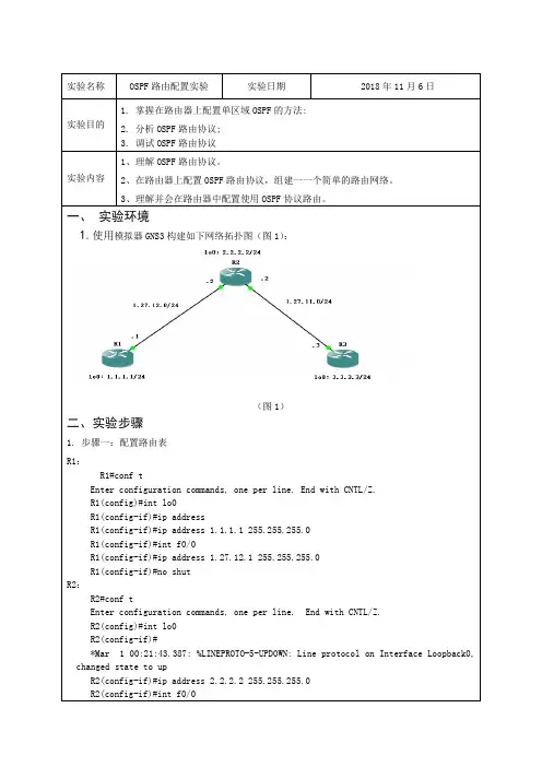
一、实验环境1.使用模拟器GNS3构建如下网络拓扑图(图1):(图1)二、实验步骤1. 步骤一:配置路由表R1:R1#conf tEnter configuration commands, one per line. End with CNTL/Z.R1(config)#int lo0R1(config-if)#ip addressR1(config-if)#ip address 1.1.1.1 255.255.255.0R1(config-if)#int f0/0R1(config-if)#ip address 1.27.12.1 255.255.255.0R1(config-if)#no shutR2:R2#conf tEnter configuration commands, one per line. End with CNTL/Z.R2(config)#int lo0R2(config-if)#*Mar 1 00:21:43.387: %LINEPROTO-5-UPDOWN: Line protocol on Interface Loopback0, changed state to upR2(config-if)#ip address 2.2.2.2 255.255.255.0R2(config-if)#int f0/0N1 - OSPF NSSA external type 1, N2 - OSPF NSSA external type 2E1 - OSPF external type 1, E2 - OSPF external type 2i - IS-IS, su - IS-IS summary, L1 - IS-IS level-1, L2 - IS-IS level-2ia - IS-IS inter area, * - candidate default, U - per-user static routeo - ODR, P - periodic downloaded static routeGateway of last resort is not set1.0.0.0/8 is variably subnetted, 3 subnets, 2 masksO 1.1.1.1/32 [110/21] via 1.27.11.2, 00:16:38, FastEthernet0/1C 1.27.11.0/24 is directly connected, FastEthernet0/1O 1.27.12.0/24 [110/20] via 1.27.11.2, 00:16:38, FastEthernet0/12.0.0.0/32 is subnetted, 1 subnetsO 2.2.2.2 [110/11] via 1.27.11.2, 00:16:38, FastEthernet0/13.0.0.0/24 is subnetted, 1 subnetsC 3.3.3.0 is directly connected, Loopback04.抓取OSPF包,在R1和R2之间的链路上5.抓包结果:成功抓到arp协议的请求和应答三、实验总结经过这次实验,我个人得到了不少的收获,一方面加深了我对课本理论的认识,另一方面也提。
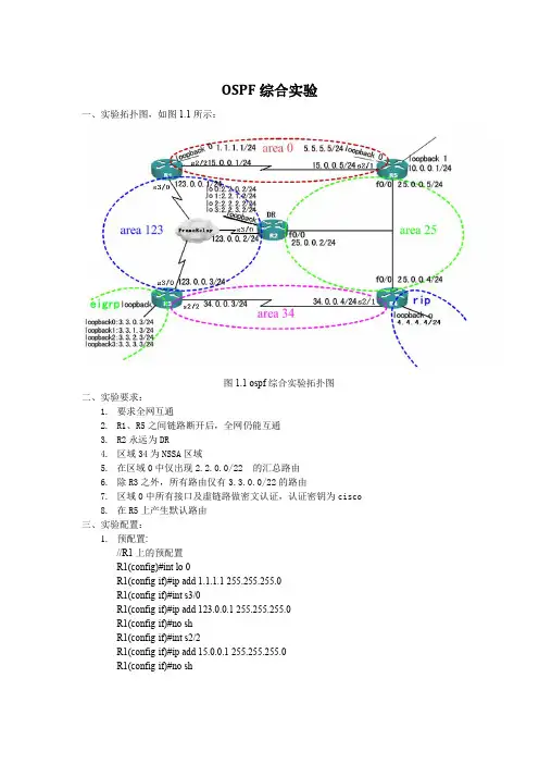
OSPF综合实验一、实验拓扑图,如图1.1所示:图1.1 ospf综合实验拓扑图二、实验要求:1.要求全网互通2.R1、R5之间链路断开后,全网仍能互通3.R2永远为DR4.区域34为NSSA区域5.在区域0中仅出现2.2.0.0/22 的汇总路由6.除R3之外,所有路由仅有3.3.0.0/22的路由7.区域0中所有接口及虚链路做密文认证,认证密钥为cisco8.在R5上产生默认路由三、实验配置:1.预配置://R1上的预配置R1(config)#int lo 0R1(config-if)#ip add 1.1.1.1 255.255.255.0R1(config-if)#int s3/0R1(config-if)#ip add 123.0.0.1 255.255.255.0R1(config-if)#no shR1(config-if)#int s2/2R1(config-if)#ip add 15.0.0.1 255.255.255.0R1(config-if)#no sh//R2上的预配置R2(config)#int lo 0R2(config-if)#ip add 2.2.0.2 255.255.255.0 R2(config-if)#int lo 1R2(config-if)#ip add 2.2.1.2 255.255.255.0 R2(config-if)#int lo 2R2(config-if)#ip add 2.2.2.2 255.255.255.0 R2(config-if)#int lo 3R2(config-if)#ip add 2.2.3.2 255.255.255.0 R2(config-if)#int s3/0R2(config-if)#ip add 123.0.0.2 255.255.255.0 R2(config-if)#no shR2(config-if)#int f0/0R2(config-if)#ip add 25.0.0.2 255.255.255.0 R2(config-if)#no sh//R3上的预配置R3(config)#int lo 0R3(config-if)#ip add 3.3.0.3 255.255.255.0 R3(config-if)#int lo 1R3(config-if)#ip add 3.3.1.3 255.255.255.0 R3(config-if)#int lo 2R3(config-if)#ip add 3.3.2.3 255.255.255.0 R3(config-if)#int lo 3R3(config-if)#ip add 3.3.3.3 255.255.255.0 R3(config-if)#int s3/0R3(config-if)#ip add 123.0.0.3 255.255.255.0 R3(config-if)#no shR3(config-if)#int s2/2R3(config-if)#ip add 34.0.0.3 255.255.255.0 R3(config-if)#no sh//R4上的预配置R4(config)#int lo 0R4(config-if)#ip add 4.4.4.4 255.255.255.0 R4(config-if)#int f0/0R4(config-if)#ip add 25.0.0.4 255.255.255.0 R4(config-if)#no shR4(config-if)#int s2/1R4(config-if)#ip add 34.0.0.4 255.255.255.0 R4(config-if)#no sh//R5上的预配置R5(config)#int lo 0R5(config-if)#ip add 5.5.5.5 255.255.255.0 R5(config-if)#int lo 1R5(config-if)#ip add 10.0.0.1 255.255.255.0R5(config-if)#int f0/0R5(config-if)#ip add 25.0.0.5 255.255.255.0R5(config-if)#no shR5(config-if)#int s2/1R5(config-if)#ip add 15.0.0.5 255.255.255.0R5(config-if)#no sh2.各路由器的上的具体配置://R1上的具体配置R1(config)#interface Loopback0R1(config-if)# ip ospf authentication message-digest //启用链路MD5认证R1(config-if)# ip ospf message-digest-key 1 md5 cisco //配置key ID及密匙R1(config-if)#interface Serial2/2R1(config-if)# ip ospf authentication message-digestR1(config-if)# ip ospf message-digest-key 1 md5 ciscoR1(config-if)#interface Serial3/0R1(config-if)# encapsulation frame-relay //帧中继封装R1(config-if)# frame-relay map ip 123.0.0.2 102 broadcast //帧中继类型配置为广播R1(config-if)# no arp frame-relay //关闭ARPR1(config-if)# no frame-relay inverse-arp//关闭inverse-arpR1(config-if)# ip ospf network broadcast //配置OSPF网络位broadcastR1(config-if)# ip ospf priority 0 //S3/0的DR/BDR的选举权R1(config-if)#router ospf 1R1(config-router)# router-id 1.1.1.1R1(config-router)# area 123 range 2.2.0.0 255.255.252.0//配置虚链路且开启md5认证R1(config-router)#$irtual-link 2.2.2.2 message-digest-key 1 md5 ciscoR1(config-router)# network 1.1.1.1 0.0.0.0 area 0R1(config-router)# network 15.0.0.1 0.0.0.0 area 0R1(config-router)# network 123.0.0.1 0.0.0.0 area 123//R2上的具体配置R2(config-if)#interface Serial3/0R2(config-if)# encapsulation frame-relayR2(config-if)# ip ospf network broadcastR2(config-if)# ip ospf priority 10R2(config-if)# no arp frame-relayR2(config-if)# frame-relay map ip 123.0.0.1 201 broadcastR2(config-if)# frame-relay map ip 123.0.0.3 203 broadcastR2(config-if)# no frame-relay inverse-arpR2(config-if)#router ospf 1R2(config-router)# router-id 2.2.2.2R2(config-router)#$rtual-link 5.5.5.5 message-digest-key 1 md5 ciscoR2(config-router)# area 123 range 2.2.0.0 255.255.252.0//手动汇总R2(config-router)#$irtual-link 1.1.1.1 message-digest-key 1 md5 ciscoR2(config-router)# network 2.2.0.0 0.0.255.255 area 123R2(config-router)# network 25.0.0.2 0.0.0.0 area 25R2(config-router)# network 123.0.0.2 0.0.0.0 area 123//R3上的具体配置R3(config)#interface Serial3/0R3(config-if)# encapsulation frame-relayR3(config-if)# ip ospf network broadcastR3(config-if)# ip ospf priority 0R3(config-if)# no arp frame-relayR3(config-if)# frame-relay map ip 123.0.0.2 302 broadcastR3(config-if)# no frame-relay inverse-arpR3(config-if)#router eigrp 1R3(config-router)# network 3.3.0.0 0.0.255.255R3(config-router)# no auto-summaryR3(config-router)#router ospf 1R3(config-router)# router-id 3.3.3.3R3(config-router)# area 34 nssaR3(config-router)# summary-address 3.3.0.0 255.255.252.0//域间汇总R3(config-router)# redistribute eigrp 1 subnets //重分布eigrp路由进ospf R3(config-router)# network 34.0.0.3 0.0.0.0 area 34R3(config-router)# network 123.0.0.3 0.0.0.0 area 123//R4上的具体配置R4(config-router)#router rip//开启rip进程R4(config-router)# version 2R4(config-router)# network 4.0.0.0R4(config-if)#router ospf 1R4(config-router)# router-id 4.4.4.4R4(config-router)#$rtual-link 5.5.5.5 message-digest-key 1 md5 ciscoR4(config-router)# area 34 nssaR4(config-router)# redistribute rip subnets//重分布rip进ospfR4(config-router)# network 25.0.0.4 0.0.0.0 area 25R4(config-router)# network 34.0.0.4 0.0.0.0 area 34//R5上的具体配置R5(config)#interface Loopback0R5(config-if)# ip ospf authentication message-digestR5(config-if)# ip ospf message-digest-key 1 md5 ciscoR5(config-if)#interface Serial2/1R5(config-if)# ip ospf authentication message-digestR5(config-if)# ip ospf message-digest-key 1 md5 ciscoR5(config-if)#router ospf 1R5(config-router)# router-id 5.5.5.5R5(config-router)#$rtual-link 4.4.4.4 message-digest-key 1 md5 ciscoR5(config-router)#$rtual-link 2.2.2.2 message-digest-key 1 md5 ciscoR5(config-router)# network 5.5.5.5 0.0.0.0 area 0R5(config-router)# network 15.0.0.5 0.0.0.0 area 0R5(config-router)# network 25.0.0.5 0.0.0.0 area 25R5(config-router)# default-information originate always //产生默认路由四、实验调试:1.查看R1上的路由表R1(config-line)#do sh ip routCodes: C - connected, S - static, R - RIP, M - mobile, B - BGPD - EIGRP, EX - EIGRP external, O - OSPF, IA - OSPF inter areaN1 - OSPF NSSA external type 1, N2 - OSPF NSSA external type 2E1 - OSPF external type 1, E2 - OSPF external type 2i - IS-IS, su - IS-IS summary, L1 - IS-IS level-1, L2 - IS-IS level-2ia - IS-IS inter area, * - candidate default, U - per-user static routeo - ODR, P - periodic downloaded static routeGateway of last resort is 15.0.0.5 to network 0.0.0.034.0.0.0/24 is subnetted, 1 subnetsO IA 34.0.0.0 [110/129] via 15.0.0.5, 00:40:45, Serial2/21.0.0.0/24 is subnetted, 1 subnetsC 1.1.1.0 is directly connected, Loopback02.0.0.0/8 is variably subnetted, 5 subnets, 2 masksO 2.2.2.2/32 [110/65] via 123.0.0.2, 00:40:45, Serial3/0O 2.2.0.0/22 is a summary, 00:40:45, Null0O 2.2.3.2/32 [110/65] via 123.0.0.2, 00:40:45, Serial3/0O 2.2.0.2/32 [110/65] via 123.0.0.2, 00:40:45, Serial3/0O 2.2.1.2/32 [110/65] via 123.0.0.2, 00:40:45, Serial3/03.0.0.0/22 is subnetted, 1 subnetsO E2 3.3.0.0 [110/20] via 123.0.0.3, 00:40:45, Serial3/04.0.0.0/24 is subnetted, 1 subnetsO E2 4.4.4.0 [110/20] via 15.0.0.5, 00:40:46, Serial2/25.0.0.0/32 is subnetted, 1 subnetsO 5.5.5.5 [110/65] via 15.0.0.5, 00:40:46, Serial2/225.0.0.0/24 is subnetted, 1 subnetsO IA 25.0.0.0 [110/65] via 123.0.0.2, 00:40:46, Serial3/0[110/65] via 15.0.0.5, 00:40:46, Serial2/2123.0.0.0/24 is subnetted, 1 subnetsC 123.0.0.0 is directly connected, Serial3/015.0.0.0/24 is subnetted, 1 subnetsC 15.0.0.0 is directly connected, Serial2/2O*E2 0.0.0.0/0 [110/1] via 15.0.0.5, 00:40:46, Serial2/2以上输出表明,R1上已经可以全网访问,收敛已完成。
实验十一 OSPF 基本配置【实验目的】掌握在路由器上配置OSPF 单区域。
【背景描述】假设校园网通过1 台三层交换机连到校园网出口路由器,路由器再和校园外的另 1 台路由器连接,现做适当配置,实现校园网内部主机与校园网外部主机的相互通信。
本实验以两台路由器、1 台三层交换机为例。
S3550 上划分有VLAN10 和VLAN50,其中VLAN10 用于连接RA,VLAN50 用于连接校园网主机。
【需求分析】需要在路由器和交换机上配置OSPF 路由协议,使全网互通,从而实现信息的共享和传递。
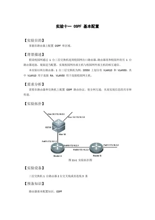
【实验拓扑】图11-1 实验拓扑图【实验设备】三层交换机1 台路由器2台交叉线或直连线3 条【预备知识】路由器基本配置知识、OSPF【实验原理】OSPF(Open Shortest Path First,开放式最短路径优先)协议,是目前网络中应用最广泛的路由协议之一。
属于内部网关路由协议,能够适应各种规模的网络环境,是典型的链路状态(link-state)协议。
OSPF 路由协议通过向全网扩散本设备的链路状态信息,使网络中每台设备最终同步一个具有全网链路状态的数据库(LSDB),然后路由器采用SPF 算法,以自己为根,计算到达其他网络的最短路径,最终形成全网路由信息。
OSPF 属于无类路由协议,支持VLSM(变长子网掩码)。
OSPF 是以组播的形式进行链路状态的通告的。
在大规模的网络环境中,OSPF 支持区域的划分,将网络进行合理规划。
划分区域时必须存在area0(骨干区域)。
其他区域和骨干区域直接相连,或通过虚链路的方式连接。
【实验步骤】第一步:在路由器和三层交换机配置IP 地址switch#configure terminalswitch(config)#hostname S3750S3750(config)#vlan 10S3750(config-vlan)#exitS3750(config)#vlan 50S3750(config-vlan)#exitS3750(config)#interface f0/1S3750(config-if)#switchport access vlan 10S3750(config-if)#exitS3750(config)#interface f0/2S3750(config-if)#switchport access vlan 50S3750(config-if)#exitS3750(config)#interface vlan 10S3750(config-if)#ip address 172.16.1.2 255.255.255.0S3750(config-if)#no shutdownS3750(config-if)#exitS3750(config)#interface vlan 50S3750(config-if)#ip address 172.16.5.1 255.255.255.0S3750(config-if)#no shutdownS3750(config-if)#exitRouterA(config)# interface fastethernet 0/1RouterA(config-if)# ip address 172.16.1.1 255.255.255.0RouterA(config-if)# no shutdownRouterA(config-if)#exitRouterA(config)# interface fastethernet 0/0RouterA(config-if)# ip address 172.16.2.1 255.255.255.0 RouterB(config-if)# no shutdownRouterB(config)# interface fastethernet 0/1RouterB(config-if)# ip address 172.16.3.1 255.255.255.0 RouterB(config-if)# no shutdownRouterB(config-if)#exitRouterB(config)# interface fastethernet 0/0RouterB(config-if)# ip address 172.16.2.2 255.255.255.0 RouterB(config-if)# no shutdown第二步:配置OSPF 路由协议S3750(config)#router ospfS3750(config-router)#network 172.16.5.0 0.0.0.255 area 0 S3750(config-router)#network 172.16.1.0 0.0.0.255 area 0 S3750(config-router)#endRouterA(config)# router ospfRouterA(config-router)#network 172.16.1.0 0.0.0.255 area 0 RouterA(config-router)#network 172.16.2.0 0.0.0.255 area 0 RouterA(config-router)#endRouterB(config)#router ospfRouterB(config-router)#network 172.16.2.0 0.0.0.255 area 0 RouterB(config-router)#network 172.16.3.0 0.0.0.255 area 0 RouterB(config-router)#end第三步:验证测试S3750#show vlanS3750#show ip interface briefInterfaceIP-Address(Pri) OK? StatusRA#show ip interface briefRB#show ip interface briefS3750#show ip routeRA#show ip routeRB#show ip routeRA#show ip ospf neighborRA#show ip ospf interface fastEthernet 0/0FastEthernet 0/0 is up, line protocol is upInternet Address 172.16.2.1/24, Ifindex 1, Area 0.0.0.0, MTU 1500 Matching network config: 172.16.2.0/24Process ID 1, Router ID 172.167.1.1, Network Type BROADCAST, Cost: 1 Transmit Delay is 1 sec, State BDR, Priority 1Designated Router (ID) 172.16.2.2, Interface Address 172.16.2.2 Backup Designated Router (ID) 172.167.1.1, Interface Address 172.16.2.1 Timer intervals configured, Hello 10, Dead 40, Wait 40, Retransmit 5 Hello due in 00:00:05Neighbor Count is 1, Adjacent neighbor count is 1Crypt Sequence Number is 82589Hello received 114 sent 115, DD received 4 sent 5LS-Req received 1 sent 1, LS-Upd received 5 sent 9LS-Ack received 6 sent 4, Discarded 0【注意事项】1、在申明直连网段时,注意要写该网段的反掩码。
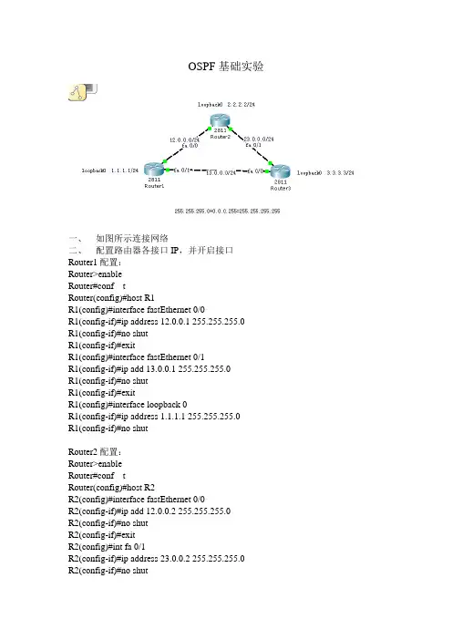
OSPF基础实验一、如图所示连接网络二、配置路由器各接口IP,并开启接口Router1配置:Router>enableRouter#conf tRouter(config)#host R1R1(config)#interface fastEthernet 0/0R1(config-if)#ip address 12.0.0.1 255.255.255.0R1(config-if)#no shutR1(config-if)#exitR1(config)#interface fastEthernet 0/1R1(config-if)#ip add 13.0.0.1 255.255.255.0R1(config-if)#no shutR1(config-if)#exitR1(config)#interface loopback 0R1(config-if)#ip address 1.1.1.1 255.255.255.0R1(config-if)#no shutRouter2配置:Router>enableRouter#conf tRouter(config)#host R2R2(config)#interface fastEthernet 0/0R2(config-if)#ip add 12.0.0.2 255.255.255.0R2(config-if)#no shutR2(config-if)#exitR2(config)#int fa 0/1R2(config-if)#ip address 23.0.0.2 255.255.255.0R2(config-if)#no shutR2(config-if)#exitR2(config)#interface loopback 100R2(config-if)#ip add 2.2.2.2 255.255.255.0R2(config-if)#exitRouter3配置:Router>enableRouter#conf tRouter(config)#host R3R3(config)#interface fastEthernet 0/1R3(config-if)#ip add 23.0.0.3 255.255.255.0R3(config-if)#no shutR3(config-if)#exitR3(config)#interface fastEthernet 0/0R3(config-if)#ip add 13.0.0.3 255.255.255.0R3(config-if)#no shutR3(config-if)#exitR3(config)#interface loopback 66R3(config-if)#ip address 3.3.3.3 255.255.255.0R3(config-if)#no shut三、启用并配置OSPF路由协议Router1配置:R1(config)#router ospf 1R1(config-router)#network 1.1.1.0 0.0.0.255 area 100R1(config-router)#network 12.0.0.0 0.0.0.255 area 100R1(config-router)#network 13.0.0.0 0.0.0.255 area 100Router2配置:R2(config)#router ospf 2R2(config-router)#network 12.0.0.0 0.0.0.255 area 100R2(config-router)#network 23.0.0.0 0.0.0.255 area 100R2(config-router)#network 2.2.2.0 0.0.0.255 area 100Router3配置:R3(config)#router ospf 3R3(config-router)#network 3.3.3.0 0.0.0.255 area 100R3(config-router)#network 23.0.0.0 0.0.0.255 area 100R3(config-router)#network 13.0.0.0 0.0.0.255 area 100四、观察各路由器路由表,发现OSPF路由条目,用ping 测试各点之间的连通性。
OSPF基本配置
一、实验名称:OSPF基本配置
二、实验环境:windows7操作系统下完成
三、实验目标:1、用若干台PC和若干台路由器构成一个网络;
2、规划PC机及路由器相关接口的IP地址,配置OSPF动态路由协议,使PC机之间能相互通信;
3、用show ip route,sh ip protocol,sh ip ospf,sh ip ospf nei,sh arp显示每台路由器上的相关信息
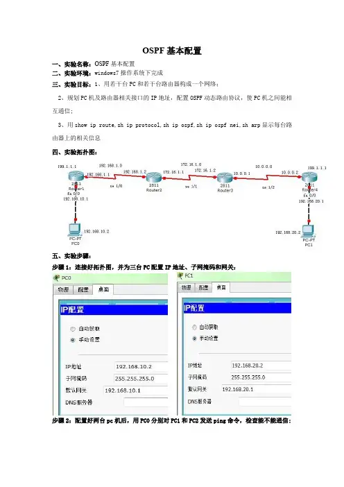
四、实验拓扑图:
五、实验步骤:
步骤1:连接好拓扑图,并为三台PC配置IP地址、子网掩码和网关:
步骤2:配置好两台pc机后,用PC0分别对PC1和PC2发送ping命令,检查能不能通信:
在没有配置路由的情况下,两台计算机之间是不能通信的。
步骤3:规划路由器相关接口的IP地址,配置OSPF动态路由协议:
步骤4:用show ip route,sh ip protocol,sh ip ospf,sh ip ospf nei,sh arp显示每台路由器上的相关信息:
实验未成功,路由没有配置好。
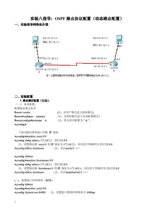
实验八指导:OSPF路由协议配置(动态路由配置)一、实验指导网络拓扑图二、实验配置A 路由器的配置(左边):(一).基本配置:配置路由器主机名Router>enable (注:从用户模式进入特权模式)Router#configure terminal (注:从特权模式进入全局配置模式)Router(config)#hostname A (注:将主机名配置为“A”)A(config)#下面为路由器各接口分配IP 地址A(config)#interface serial 0/0A(config-if)#ip address 172.16.2.2 255.255.0.0注:设置路由器serial 0 的IP 地址为172.16.2.2,对应的子网掩码为255.255.0.0A(config-if)#no shutdown (注:开启serial 0 口)A(config-if)#exitA(config)#interface fastethernet 0/0A(config-if)#ip address 171.16.3.1 255.255.0.0注:设置路由器fastethernet 0 的IP 地址为172.16.3.1,对应的子网掩码为255.255.0.0A(config-if)#no shutdown (注:开启fastethernet 0 口)(二).配置接口时钟频率(DCE):A(config-if)#exitA(config)#interface serial 0/0A(config-if)clock rate 64000 注:设置接口物理时钟频率为64Kbps(三).配置OSPF路由协议:A(config-if)#exitA(config)#router ospf 1 (注:在路由器A上启用路由协议OSPF) A(config-router)#network 171.16.0.0 0.0.255.255 area 0A(config-router)#network 172.16.0.0 0.0.255.255 area 0(注:1.公布属于171.16.0.0主类的子网;2.包含在172.16.0.0主类内的接口发送接收路由信息)B 路由器的配置(右边):(一).基本配置:配置路由器主机名Router>enable (注:从用户模式进入特权模式)Router#configure terminal (注:从特权模式进入全局配置模式)Router(config)#hostname B (注:将主机名配置为“B”)B(config)#下面为路由器各接口分配IP 地址B(config)#interface serial 0/0B(config-if)#ip address 172.16.2.1 255.255.0.0B(config-if)#no shutdown (注:开启serial 0 口)B(config-if)#exitB(config)#interface fastethernet 0/0B(config-if)#ip address 173.18.3.1 255.255.0.0B(config-if)#no shutdown (注:开启fastethernet 0 口)(二).配置OSPF路由协议:B(config-if)#exitB(config)#router ospf 1 (注:启用路由器B的OSPF协议)B(config-router)#network 172.16.0.0 0.0.255.255 area 0B(config-router)#network 173.18.0.0 0.0.255.255 area 0(注:1.公布属于172.16.0.0主类的子网;2.包含在173.18.0.0主类内的接口发送接收路由信息)三、验证命令:show ip int briefshow ip routeshow ip protocolsshow ip ospfshow ip ospf interfaceshow ip ospf databaseping四、实验结果1.查看A,B路由器中路由项。
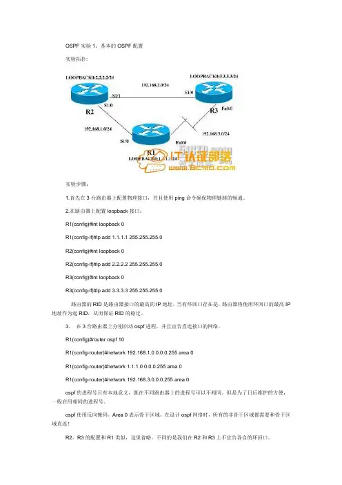
OSPF实验1:基本的OSPF配置实验拓扑:实验步骤:1.首先在3台路由器上配置物理接口,并且使用ping命令确保物理链路的畅通。
2.在路由器上配置loopback接口:R1(config)#int loopback 0R1(config-if)#ip add 1.1.1.1 255.255.255.0R2(config)#int loopback 0R2(config-if)#ip add 2.2.2.2 255.255.255.0R3(config)#int loopback 0R3(config-if)#ip add 3.3.3.3 255.255.255.0路由器的RID是路由器接口的最高的IP地址,当有环回口存在是,路由器将使用环回口的最高IP 地址作为起RID,从而保证RID的稳定。
3.在3台路由器上分别启动ospf进程,并且宣告直连接口的网络。
R1(config)#router ospf 10R1(config-router)#network 192.168.1.0 0.0.0.255 area 0R1(config-router)#network 1.1.1.0 0.0.0.255 area 0R1(config-router)#network 192.168.3.0.0.0.255 area 0ospf的进程号只有本地意义,既在不同路由器上的进程号可以不相同。
但是为了日后维护的方便,一般启用相同的进程号。
ospf使用反向掩码。
Area 0表示骨干区域,在设计ospf网络时,所有的非骨干区域都需要和骨干区域直连!R2,R3的配置和R1类似,这里省略。
不同的是我们在R2和R3上不宣告各自的环回口。
*Aug 13 17:58:51.411: %OSPF-5-ADJCHG: Process 10, Nbr 2.2.2.2 on Serial1/0 from LOADING to FULL, Loading Done配置结束后,我们可以看到邻居关系已经到达FULL状态。
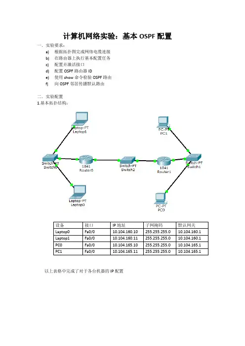
计算机网络实验:基本OSPF配置一.实验要求:a)根据拓扑图完成网络电缆连接b)在路由器上执行基本配置任务c)配置并激活接口d)配置OSPF路由器IDe)使用show命令检验OSPF路由f)向OSPF邻居传播默认路由二.实验配置1.基本拓扑结构:以上表格中完成了对于各台机器的IP配置此为第一个小网络,需要对Route0进行配置:(注意是哪个接口)对应的IP地址改为10.104.160.1,子网掩码为255.255.255.0此为第二个小网络,需要对Route1进行配置:(注意是哪个接口)对应的IP地址改为10.104.165.1,子网掩码为255.255.255.0此为第三个小网络,需要对Route0和Route1进行配置:(注意对应的接口)这是一个新的小网络,所以两个路由器的IP地址不能相同,此实验中我的设置为:Route0的IP地址为10.104.1.1,子网掩码为255.255.255.0Route1的IP地址为10.104.1.2,子网掩码为255.255.255.0到此,拓扑结构构建完毕。
2.对各路由器进行OSPF设置,以Route0为例:打开Route0的CLI窗口,如图:输入exit命令,直到出现Route#输入configure terminal,如图:接下来输入router ospf 1,如图:输入配置LAN的network语句:将本路由器连接的几个子网IP的网络号输入进去,然后子网掩码为255.255.255.0的补码即为0.0.0.255,再加上area 0代表为第一个网络。
配置后以end结束。
如图:同理Route1的配置方法类似3.对LAN的配置进行检查。
在Route0和Route1的CLI中输入show ip route如图:注意最下面的O一项,说明OSPF协议已经正常工作,C的两项是初始化配置。
4.检验网络能否正常工作检查Route0:检查Route1:检查Route0和Route1能否正常进行数据交换:三.实验总结这个实验考察的是对OSPF协议的理解与基本的IP配置,其中也有些小细节需要注意的,如路由器和路由器通过交换机连接时也会作为一个小网络,IP地址不能相同。
ospf配置实验报告OSPF 配置实验报告一、实验目的本次实验的主要目的是深入理解和掌握开放式最短路径优先(Open Shortest Path First,OSPF)协议的工作原理,并通过实际配置和测试,熟练掌握 OSPF 在网络中的应用。
二、实验环境1、网络拓扑结构本次实验使用了如下图所示的网络拓扑结构:此处插入网络拓扑图该拓扑包括了三台路由器 R1、R2 和 R3,以及若干台连接在路由器上的终端设备。
2、设备及软件使用的路由器型号为_____,配置终端软件为_____。
三、实验原理OSPF 是一种链路状态路由协议,它通过收集网络中各个路由器的链路状态信息,构建出整个网络的拓扑结构,并基于此计算出最短路径。
OSPF 工作过程主要包括以下几个步骤:1、发现邻居:路由器通过发送Hello 报文来发现和维护邻居关系。
2、交换链路状态信息:邻居路由器之间交换链路状态通告(LSA),以描述网络拓扑和链路状态。
3、计算路由:根据收到的 LSA,路由器使用迪杰斯特拉算法计算出到各个目的地的最短路径,并生成路由表。
四、实验步骤1、基本配置为每台路由器配置接口 IP 地址。
启用 OSPF 进程,并指定区域号。
配置路由器的 Router ID。
以 R1 为例,配置命令如下:```interface GigabitEthernet0/0ip address 19216811 2552552550interface GigabitEthernet0/1ip address 19216821 2552552550router ospf 1routerid 1111network 19216810 000255 area 0network 19216820 000255 area 0```2、配置 OSPF 区域将网络划分为不同的区域,以减少路由信息的传播范围和复杂度。
配置区域类型,如骨干区域(Area 0)和非骨干区域。
实验十一路由器OSPF动态路由配置实验目的:1、掌握OSPF 协议的配置方法;2、掌握查看通过动态路由协议OSPF 学习产生的路由。
实验设备:PC;Switch_3560;Router-PT;直连线;交叉线;DCE 串口线实验背景:假设校园网通过一台三层交换机连到校园网出口路由器上,路由器再和校园外的另一台路由器连接。
现要做适当配置,实现校园网内部主机与校园网外部主机之间的相互通信。
为了简化网管的管理维护工作,学校决定采用 OSPF 协议实现互通。
实验原理:OSPF 开放式最短路径优先协议,是目前网路中应用最广泛的路由协议之一。
属于内部网管路由协议,能够适应各种规模的网络环境,是典型的链路状态协议。
OSPF 路由协议通过向全网扩散本设备的链路状态信息,使网络中每台设备最终同步一个具有全网链路状态的数据库,然后路由器采用 SPF 算法,以自己为根,计算到达其他网络的最短路径,最终形成全网路由信息。
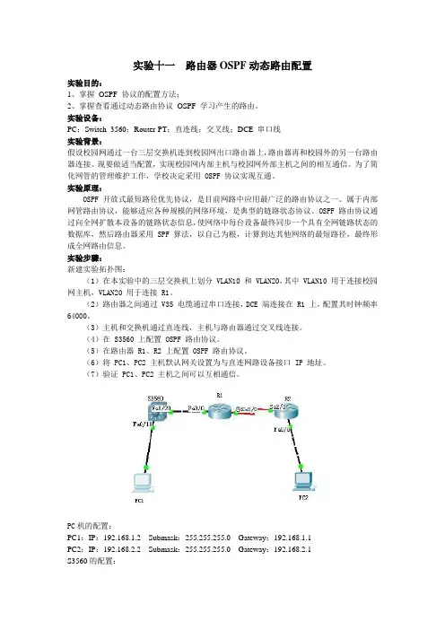
实验步骤:新建实验拓扑图:(1)在本实验中的三层交换机上划分 VLAN10 和 VLAN20,其中 VLAN10 用于连接校园网主机,VLAN20 用于连接 R1。
(2)路由器之间通过 V35 电缆通过串口连接,DCE 端连接在 R1 上,配置其时钟频率64000。
(3)主机和交换机通过直连线,主机与路由器通过交叉线连接。
(4)在 S3560 上配置 OSPF 路由协议。
(5)在路由器 R1、R2 上配置 OSPF 路由协议。
(6)将 PC1、PC2 主机默认网关设置为与直连网路设备接口 IP 地址。
(7)验证 PC1、PC2 主机之间可以互相通信。
PC机的配置:PC1:IP:192.168.1.2 Submask:255.255.255.0 Gateway:192.168.1.1PC2:IP:192.168.2.2 Submask:255.255.255.0 Gateway:192.168.2.1S3560的配置:conf thostname S3560vlan 10exitvlan 20interface fa 0/10switchport access vlan 10exitint fa 0/20switchport access valn 20exitinterface valn 10ip address 192.168.1.1 255.255.255.0no shutdownexitinterface vlan 20ip address 192.168.3.1 255.255.255.0no shutdownendshow ip routeconf trouter ospf 1 //运行OSPF协议,进程ID为1。
实验十一配置OSPF路由协议实验背景:OSPF(Open Shortest Path First)是一个内部网关协议(IGP),用于在一个自治系统(AS)内部进行路由选择。
OSPF使用链路状态数据库(LSDB)来记录网络拓扑信息,并通过计算最短路径树来确定最佳路径。
在本实验中,将学习如何配置OSPF路由协议,以在网络中实现动态路由。
实验目标:1.在网络中配置OSPF路由协议。
2.根据网络中的需求调整OSPF路由设置。
3.验证配置的正确性,并测试动态路由的性能。
实验材料:1.三台路由器(R1、R2和R3)。
2.两台终端设备(PC1和PC2)。
3.连接路由器和终端设备的适当数量的以太网电缆。
实验步骤:1.连接设备:a. 将R1的Ethernet 0/0接口连接到R2的Ethernet 0/0接口。
b. 将R1的Ethernet 0/1接口连接到PC1的网卡。
c. 将R2的Ethernet 0/1接口连接到R3的Ethernet 0/0接口。
d. 将R3的Ethernet 0/1接口连接到PC2的网卡。
2.配置基本网络设置:a.在每台路由器上配置主机名和密码:R1(config)# hostname R1R1(config)# enable secret <password>R2(config)# hostname R2R2(config)# enable secret <password>R3(config)# hostname R3R3(config)# enable secret <password>b.配置每台路由器的接口IP地址:R1(config)# interface Ethernet 0/0R1(config-if)# ip address <ip_address> <subnet_mask> R1(config)# interface Ethernet 0/1R1(config-if)# ip address <ip_address> <subnet_mask> R2(config)# interface Ethernet 0/0R2(config-if)# ip address <ip_address> <subnet_mask> R2(config)# interface Ethernet 0/1R2(config-if)# ip address <ip_address> <subnet_mask> R3(config)# interface Ethernet 0/0R3(config-if)# ip address <ip_address> <subnet_mask>R3(config)# interface Ethernet 0/1R3(config-if)# ip address <ip_address> <subnet_mask>c.配置每台PC的IP地址和默认网关:PC1> ip <ip_address> <subnet_mask> <default_gateway>PC2> ip <ip_address> <subnet_mask> <default_gateway>3.配置OSPF协议:a.在每个路由器上启用OSPF:R1(config)# router ospf <process_id>R1(config-router)# network <network_address> <wildcard_mask> area <area_id>R2(config)# router ospf <process_id>R2(config-router)# network <network_address> <wildcard_mask> area <area_id>R3(config)# router ospf <process_id>R3(config-router)# network <network_address> <wildcard_mask> area <area_id>b.在R1和R3之间配置OSPF邻居:R1(config-router)# neighbor <R3_interface_ip_address><R3_interface>R3(config-router)# neighbor <R1_interface_ip_address> <R1_interface>c.在PC1和PC2上检查IP连接以验证OSPF配置的正确性。
实验OSPF单区域基本配置【实验名称】OSPF单区域基本配置【实验目的】OSPF基本配置技术。
【背景描述】你是某集成商的高级技术支持工程师,现在让你为某企业设计一个网络骨干结构,你选择了使用ospf路由协议来构建。
【实现功能】构建OSPF骨干区域,为网络拓展打基础。
【实验拓扑】【实验设备】R2624路由器(2台)、V35DCE(1根)、V35DTE(1根)【实验步骤】第一步:基本配置Red-Giant>enRed-Giant#conf tRed-Giant(config)#hostname R1 !更改路由器主机名R1(config)#int s0R1(config-if)#ip add 192.168.12.1 255.255.255.0 !为接口配置地址R1(config-if)#clock rate 64000 ! 设置时钟速率在DTE端不用设置R1(config-if)#no shRed-Giant>enRed-Giant#conf tRed-Giant(config)#hostname R2R2(config)#int s0R2(config-if)#ip add 192.168.12.2 255.255.255.0R2(config-if)#no sh验证测试:pingR2#ping 192.168.12.1Sending 5, 100-byte ICMP Echoes to 192.168.12.1, timeout is 2 seconds:!!!!!第二步:启动OSPF路由协议R1(config)#router ospf 1 !启动ospf进程R1(config-router)#net 192.168.12.0 0.0.0.255 area 0 ! 声明网段属于区域0R1(config-router)#endR2(config)#router ospf 1R2(config-router)#net 192.168.12.0 0.0.0.255 area 0R2(config-router)#end验证测试:R1# sh ip os nei (以R1为例)Neighbor ID Pri State Dead Time Address Interface 192.168.12.2 1 FULL/ - 00:00:37 192.168.12.2 Serial0【注意事项】●在广域网口DCE端要配置时钟速率;●ospf进程建议相同的进程号,利于网络规划管理;●声明网段后,掩码用反掩码。
ospf配置实验报告《OSPF配置实验报告》在网络配置和管理中,Open Shortest Path First(OSPF)是一种常用的路由协议,用于在IP网络中进行动态路由选择。
本实验报告将介绍如何进行OSPF配置,并通过实验验证其功能和效果。
实验环境:- 两台路由器设备- 一台交换机设备- 一台PC设备- 网线、电源线等相关设备实验步骤:1. 连接设备:将两台路由器设备和交换机设备通过网线连接起来,确保连接正确稳定。
2. 配置路由器:登录路由器设备的管理界面,进行OSPF配置。
首先配置路由器的IP地址和子网掩码,然后启用OSPF协议,并配置相关参数,如区域ID、网络地址等。
3. 配置交换机:登录交换机设备的管理界面,配置VLAN和端口,确保路由器和PC设备能够正常通信。
4. 验证网络:通过ping命令验证PC设备能够与路由器设备进行正常通信,检查网络连接是否正常。
5. 测试路由选择:在路由器设备上进行路由表查看和调试命令,验证OSPF协议是否能够正确选择最佳路径。
实验结果:经过以上步骤的配置和验证,实验结果表明OSPF协议能够成功实现动态路由选择,并且网络通信正常稳定。
通过查看路由表和调试信息,可以清晰地看到OSPF协议选择了最佳路径,并且能够动态调整路由信息以适应网络拓扑的变化。
结论:本实验验证了OSPF配置的功能和效果,证明了OSPF协议在IP网络中的重要性和实用性。
通过OSPF协议,网络管理员可以轻松实现动态路由选择和网络优化,提高网络性能和稳定性。
总结:OSPF配置实验报告详细介绍了OSPF协议的配置步骤和验证方法,通过实验结果验证了OSPF协议的功能和效果。
希望本实验报告能够帮助读者更加深入了解和掌握OSPF协议的配置和应用,为网络管理工作提供参考和指导。
ospf配置实验报告OSPF配置实验报告一、实验目的本实验旨在通过配置OSPF(开放最短路径优先)协议,实现网络中路由器之间的动态路由选择,并验证其可行性和有效性。
二、实验环境本实验使用了三台路由器,分别命名为R1、R2和R3。
它们之间通过以太网连接,并配置了各自的IP地址。
三、实验步骤1. 配置IP地址在每台路由器上分别配置IP地址。
以R1为例,进入路由器的配置模式,输入以下命令:```R1(config)# interface ethernet0/0R1(config-if)# ip address 192.168.1.1 255.255.255.0R1(config-if)# no shutdown```同样地,对于R2和R3,分别配置IP地址为192.168.1.2和192.168.1.3。
2. 配置OSPF协议在每台路由器上配置OSPF协议,使其能够互相通信。
以R1为例,进入路由器的配置模式,输入以下命令:```R1(config)# router ospf 1R1(config-router)# network 192.168.1.0 0.0.0.255 area 0```同样地,对于R2和R3,分别配置区域号为0,网络地址为192.168.1.0/24。
3. 验证配置结果在每台路由器上查看OSPF邻居关系是否建立成功。
以R1为例,输入以下命令:```R1# show ip ospf neighbor```如果OSPF邻居关系建立成功,将显示R2和R3的IP地址。
4. 测试路由选择在R1上配置一个路由器接口的故障,模拟网络中的链路故障。
以R1为例,进入路由器的配置模式,输入以下命令:```R1(config)# interface ethernet0/0R1(config-if)# shutdown```此时,R1与R2之间的链路将被切断。
在R2上查看路由表,输入以下命令:```R2# show ip route```可以看到R2的路由表中已经没有R1的网络地址。
实验 11.6.1:基本 OSPF 配置实验学习目标完成本实验后,您将能够:•根据拓扑图完成网络电缆连接•删除路由器启动配置并将其重新加载到默认状态•在路由器上执行基本配置任务•配置并激活接口•在所有路由器上配置 OSPF 路由•配置 OSPF 路由器 ID•使用 show 命令检验 OSPF 路由•配置静态默认路由•向 OSPF 邻居传播默认路由•配置 OSPF Hello 计时器和 Dead 计时器•在多路访问网络上配置 OSPF•配置 OSPF 优先级•理解 OSPF 选举过程•记录 OSPF 配置场景在本实验练习中有两个独立的场景。
在第一个场景中,您将使用场景 A 中的拓扑图所示的网络学习如何配置 OSPF 路由协议。
该网络中的各个网段使用 VLSM 划分了子网。
OSPF 是一种无类路由协议,可用于在路由更新中提供子网掩码信息。
这将使 VLSM 子网信息可传播到整个网络。
在第二个场景中,您将学习在多路访问网络中配置 OSPF。
您还将学习使用 OSPF 选举过程来确定指定路由器 (DR)、后备指定路由器 (BDR) 和 DRother 状态。
场景 A:基本 OSPF 配置拓扑图地址表设备接口IP 地址子网掩码默认网关Fa0/0 172.16.1.17 255.255.255.240 不适用R1S0/0/0 192.168.10.1 255.255.255.252 不适用S0/0/1 192.168.10.5 255.255.255.252 不适用Fa0/0 10.10.10.1 255.255.255.0 不适用R2S0/0/0 192.168.10.2 255.255.255.252 不适用S0/0/1 192.168.10.9 255.255.255.252 不适用Fa0/0 172.16.1.33 255.255.255.248 不适用R3S0/0/0 192.168.10.6 255.255.255.252 不适用S0/0/1 192.168.10.10 255.255.255.252 不适用PC1 网卡172.16.1.20 255.255.255.240 172.16.1.17 PC2 网卡10.10.10.10 255.255.255.0 10.10.10.1 PC3 网卡172.16.1.35 255.255.255.248 172.16.1.33任务 1:准备网络。
步骤 1:根据拓扑图所示完成网络电缆连接。
您可使用实验室中现有的、具有拓扑中所示接口的路由器。
注意:如果您使用 1700、2500 或 2600 路由器,则路由器输出和接口描述将有所差异。
步骤 2:清除路由器上现有的配置。
任务 2:执行基本路由器配置。
根据下列指导原则在路由器 R1、R2 和 R3 上执行基本配置:1. 配置路由器主机名。
2. 禁用查找。
DNS3. 配置特权执行模式口令。
4. 配置当日消息标语。
5. 为控制台连接配置口令。
6. 为连VTY 接配置口令。
任务 3:配置并激活串行地址和以太网地址。
步骤 1:在 R1、R2 和 R3 上配置接口。
使用拓扑图下方的表中的 IP 地址在路由器 R1、R2 和 R3 上配置接口。
步骤 2:检验 IP 地址和接口。
使用show ip interface brief命令检验 IP 地址是否正确以及接口是否已激活。
完成后,确保将运行配置保存到路由器的 NVRAM 中。
步骤 3:配置 PC1、PC2 和 PC3 的以太网接口。
使用拓扑图下方的表格中的 IP 地址和默认网关配置 PC1、PC2 和 PC3 的以太网接口。
步骤 4:通过在 PC 上 ping 默认网关测试 PC 配置。
任务 4:在路由器 R1 上配置 OSPF步骤 1:在路由器 R1 上,在全局配置模式下使用 router ospf 命令启用 OSPF。
对于process-ID参数,输入进程 ID 1。
R1(config)#router ospf 1R1(config-router)#步骤 2:配置 LAN 的network语句。
一旦您处于 OSPF 配置子模式后,请将 LAN 172.16.1.16/28 配置为包括在从 R1 发出的 OSPF 更新中。
与 EIGRP相似,OSPF network命令也使用network-address和wildcard-mask参数组合。
但与 EIGRP 不同的一点是,在 OSPF 中必须输入通配符掩码。
对于area-id参数,使用区域 ID 0。
我们将在本拓扑的所有network语句中使用 0 作为 OSPF 区域 ID。
R1(config-router)#network 172.16.1.16 0.0.0.15 area 0R1(config-router)#步骤 3:配置路由器,使其通告 Serial0/0/0 接口所连接的网络 192.168.10.0/30。
R1(config-router)#network 192.168.10.0 0.0.0.3 area 0R1(config-router)#步骤 4:配置路由器,使其通告 Serial0/0/1 接口所连接的网络 192.168.10.4/30。
R1(config-router)#network 192.168.10.4 0.0.0.3 area 0R1(config-router)#步骤 5:在 R1 上完成 OSPF 配置后,返回到特权执行模式。
R1(config-router)#end%SYS-5-CONFIG_I:Configured from console by consoleR1#任务 5:在路由器 R2 和 R3 上配置 OSPF步骤 1:使用 router ospf 命令在路由器 R2 上启用 OSPF 路由。
使用 1 作为进程 ID。
R2(config)#router ospf 1R2(config-router)#步骤 2:配置路由器,使其在 OSPF 更新中通告 LAN 10.10.10.0/24。
R2(config-router)#network 10.10.10.0 0.0.0.255 area 0R2(config-router)#步骤 3:配置路由器,使其通告 Serial0/0/0 接口所连接的网络 192.168.10.0/30。
R2(config-router)#network 192.168.10.0 0.0.0.3 area 0R2(config-router)#00:07:27: %OSPF-5-ADJCHG:Process 1, Nbr 192.168.10.5 on Serial0/0/0 from EXCHANGE to FULL, Exchange Done请注意,当将从 R1 到 R2 的串行链路添加到 OSPF 配置时,路由器会向控制台发送一条通知消息,声明已与另一台 OSPF 路由器建立相邻关系。
步骤 4:配置该路由器,使其通告 Serial0/0/1 接口所连接的网络 192.168.10.8/30。
完成后,返回到特权执行模式。
R2(config-router)#network 192.168.10.8 0.0.0.3 area 0R2(config-router)#end%SYS-5-CONFIG_I:Configured from console by consoleR2#步骤 5:在 R3 上使用router ospf和network命令配置 OSPF。
使用 1 作为进程 ID 配置该路由器,使其通告三个直连网络。
完成后,返回到特权执行模式。
R3(config)#router ospf 1R3(config-router)#network 172.16.1.32 0.0.0.7 area 0R3(config-router)#network 192.168.10.4 0.0.0.3 area 0R3(config-router)#00:17:46: %OSPF-5-ADJCHG:Process 1, Nbr 192.168.10.5 on Serial0/0/0 from LOADING to FULL, Loading DoneR3(config-router)#network 192.168.10.8 0.0.0.3 area 0R3(config-router)#00:18:01: %OSPF-5-ADJCHG:Process 1, Nbr 192.168.10.9 on Serial0/0/1 from EXCHANGE to FULL, Exchange DoneR3(config-router)#end%SYS-5-CONFIG_I:Configured from console by consoleR3#请注意,将从 R3 到 R1 以及从 R3 到 R2 的串行链路添加到 OSPF 配置时,该路由器会向控制台发送一条通知消息,声明已与另一台 OSPF 路由器建立相邻关系。
任务 6:配置 OSPF 路由器 IDOSPF 路由器 ID 用于在 OSPF 路由域内唯一标识每台路由器。
一个路由器 ID 其实就是一个 IP 地址。
Cisco 路由器按下列顺序根据下列三个条件得出路由器 ID:1. 通过 OSPF router-id命令配置的 IP 地址。
2. 路由器的环回地址中的最高 IP 地址。
3. 路由器的所有物理接口的最高活动 IP 地址。
步骤 1:检查拓扑中当前的路由器 ID。
因为这三台路由器上未配置路由器 ID 或环回接口,所以各台路由器的路由器 ID 由各自活动接口的最高 IP 地址确定。
R1 的路由器 ID 是什么? ____________________R2 的路由器 ID 是什么? ____________________R3 的路由器 ID 是什么? ____________________还可在show ip protocols、show ip ospf和show ip ospf interfaces命令的输出中看到路由器 ID。
R3#show ip protocolsRouting Protocol is "ospf 1"Outgoing update filter list for all interfaces is not setIncoming update filter list for all interfaces is not setRouter ID 192.168.10.10Number of areas in this router is 1. 1 normal 0 stub 0 nssaMaximum path: 4<省略部分输出>R3#show ip ospfRouting Process "ospf 1" with ID 192.168.10.10Supports only single TOS(TOS0) routesSupports opaque LSASPF schedule delay 5 secs, Hold time between two SPFs 10 secs<省略部分输出>R3#show ip ospf interfaceFastEthernet0/0 is up, line protocol is upInternet address is 172.16.1.33/29, Area 0Process ID 1, Router ID 192.168.10.10, Network Type BROADCAST, Cost: 1 Transmit Delay is 1 sec, State DR, Priority 1Designated Router (ID) 192.168.10.10, Interface address 172.16.1.33 No backup designated router on this networkTimer intervals configured, Hello 10, Dead 40, Wait 40, Retransmit 5 Hello due in 00:00:00Index 1/1, flood queue length 0Next 0x0(0)/0x0(0)Last flood scan length is 1, maximum is 1Last flood scan time is 0 msec, maximum is 0 msecNeighbor Count is 0, Adjacent neighbor count is 0Suppress hello for 0 neighbor(s)<省略部分输出>R3#步骤 2:使用环回地址来更改拓扑中路由器的路由器 ID。