Designation:A 335/A 335M –03
Standard Speci?cation for
Seamless Ferritic Alloy-Steel Pipe for High-Temperature Service 1
This standard is issued under the ?xed designation A 335/A 335M;the number immediately following the designation indicates the year of original adoption or,in the case of revision,the year of last revision.A number in parentheses indicates the year of last reapproval.A superscript epsilon (e )indicates an editorial change since the last revision or reapproval.This standard has been approved for use by agencies of the Department of Defense.
1.Scope *
1.1This speci?cation 2covers nominal wall and minimum wall seamless ferritic alloy-steel pipe intended for high-temperature service.Pipe ordered to this speci?cation shall be suitable for bending,?anging (vanstoning),and similar form-ing operations,and for fusion welding.Selection will depend upon design,service conditions,mechanical properties,and high-temperature characteristics.
1.2Several grades of ferritic steels (see Note 1)are covered.Their compositions are given in Table 1.
N OTE 1—Ferritic steels in this speci?cation are de?ned as low-and intermediate-alloy steels containing up to and including 10%chromium.
1.3Supplementary requirements (S1to S7)of an optional nature are provided.These supplementary requirements call for additional tests to be made,and when desired,shall be so stated in the order together with the number of such tests required.1.4The values stated in either inch-pound units or SI units are to be regarded separately as standard.Within the text,the SI units are shown in brackets.The values stated in each system are not exact equivalents;therefore,each system must be used independently of the https://www.doczj.com/doc/523117733.html,bining values from the two systems may result in nonconformance with the speci?-cation.The inch-pound units shall apply unless the “M”designation of this speci?cation is speci?ed in the order.
N OTE 2—The dimensionless designator NPS (nominal pipe size)has been substituted in this standard for such traditional terms as “nominal diameter,”“size,”and “nominal size.”
2.Referenced Documents 2.1ASTM Standards:
A 450/A 450M Speci?cation for General Requirements for
Carbon,Ferritic Alloy,and Austenitic Alloy Steel Tubes 3A 999/A 999M Speci?cation for General Requirements for Alloy and Stainless Steel Pipe 3
E 213Practice for Ultrasonic Examination of Metal Pipe and Tubing 4
E 309Practice for Eddy-Current Examination of Steel Tu-bular Products Using Magnetic Saturation 4
E 381Method of Macroetch Testing Steel Bars,Billets,Blooms,and Forgings 5
E 527Practice for Numbering Metals and Alloys (UNS)3E 570Practice for Flux Leakage Examination of Ferromag-netic Steel Tubular Products 42.2Other Documents:
SNT-TC-1A Recommended Practice for Nondestructive Personnel Quali?cation and Certi?cation 6
SAE J 1086Practice for Numbering Metals and Alloys (UNS)73.Ordering Information
3.1Orders for material under this speci?cation should include the following,as required,to describe the desired material adequately:
3.1.1Quantity (feet,metres,or number of lengths),3.1.2Name of material (seamless alloy steel pipe),3.1.3Grade (Table 1),
3.1.4Manufacture (hot-?nished or cold-drawn),3.1.5Size using one of the following:3.1.5.1NPS and schedule number,
3.1.5.2Outside diameter and nominal wall thickness,3.1.5.3Outside diameter and minimum wall thickness,3.1.5.4Inside diameter and nominal wall thickness,and 3.1.5.5Inside diameter and minimum wall thickness.3.1.6Length (speci?c or random),
1
This speci?cation is under the jurisdiction of ASTM Committee A01on Steel,Stainless Steel and Related Alloysand is the direct responsibility of Subcommittee A01.10on Stainless and Alloy Steel Tubular Products.
Current edition approved Apr.10,2003.Published May 2003.Originally approved in https://www.doczj.com/doc/523117733.html,st previous edition approved in 2002as A 335/A 335M-02.2
For ASME Boiler and Pressure Vessel Code applications see related Speci?-cation SA-335in Section II of that Code.
3
Annual Book of ASTM Standards ,V ol 01.01.4Annual Book of ASTM Standards ,V ol 03.03.5
Annual Book of ASTM Standards ,V ol 03.01.6
Available from the American Society for Nondestructive Testing,1711Arlin-gate Plaza,PO Box 28518,Columbus,OH 43228-0518.7
Available from Society of Automotive Engineers,400Commonwealth Drive,Warrendale,PA 15096.
1
*A Summary of Changes section appears at the end of this standard.
Copyright ?ASTM International,100Barr Harbor Drive,PO Box C700,West Conshohocken,PA 19428-2959,United
States.
3.1.7End?nish(Ends Section of Speci?cation A999/ A999M),
3.1.8Optional requirements(Section8,11and12of this speci?cation.See the Sections on Hydrostatic Test Require-ments and Permissible Variation in Weight for Seamless Pipe in Speci?cation A999/A999M),
3.1.9Test report required(Certi?cation Section of Speci?-cation A999/A999M),
3.1.10Speci?cation designation,and
3.1.11Special requirements or any supplementary require-ments selected,or both.
4.General Requirements
4.1Material furnished to this speci?cation shall conform to the applicable requirements of the current edition of Speci?-cation A999/A999M,unless otherwise provided herein.
5.Materials and Manufacture
5.1Pipe may be either hot?nished or cold drawn with the ?nishing treatment as required in5.3.
5.2Grade P2and P12—The steel shall be made by coarse-grain melting practice.Speci?c limits,if any,on grain size or deoxidation practice shall be a matter of agreement between the manufacturer and purchaser.
5.3Heat Treatment:
5.3.1All pipe of grades shown in Table1except P5c,P23 P91,P92,P122,and P911as provided in 5.3.2,shall be reheated and furnished in the full-annealed,isothermal an-nealed,or normalized and tempered condition.If furnished in the normalized and tempered condition,the minimum temper-ing temperature for Grades P5,P5b,P9,P21,and P22shall be 1250°F[675°C],the minimum tempering temperature for Grades P1,P2,P11,P12,and P15shall be1200°F[650°C].
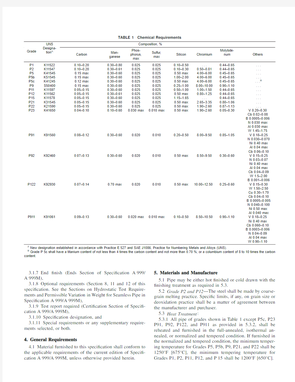
TABLE1Chemical Requirements
Grade
UNS
Designa-
tion A
Composition,%
Carbon
Man-
ganese
Phos-
phorus,
max
Sulfur,
max
Silicon Chromium
Molybde-
num Others
P1K115220.10–0.200.30–0.800.0250.0250.10–0.50...0.44–0.65...
P2K115470.10–0.200.30–0.610.0250.0250.10–0.300.50–0.810.44–0.65...
P5K415450.15max0.30–0.600.0250.0250.50max 4.00–6.000.45–0.65...
P5b K515450.15max0.30–0.600.0250.025 1.00–2.00 4.00–6.000.45–0.65...
P5c K412450.12max0.30–0.600.0250.0250.50max 4.00–6.000.45–0.65...B P9S504000.15max0.30–0.600.0250.0250.25–1.008.00–10.000.90–1.10...
P11K115970.05–0.150.30–0.600.0250.0250.50–1.00 1.00–1.500.44–0.65...
P12K115620.05–0.150.30–0.610.0250.0250.50max0.80–1.250.44–0.65...
P15K115780.05–0.150.30–0.600.0250.025 1.15–1.65...0.44–0.65...
P21K315450.05–0.150.30–0.600.0250.0250.50max 2.65–3.350.80–1.06...
P22K215900.05–0.150.30–0.600.0250.0250.50max 1.90–2.600.87–1.13...
P23K416500.04–0.100.10–0.600.030max0.010max0.50max 1.90–2.600.05–0.30V0.20–0.30
Cb0.02–0.08
B0.0005–0.006
N0.030max
Al0.030max
W1.45–1.75 P91K915600.08–0.120.30–0.600.0200.0100.20–0.508.00–9.500.85–1.05V0.18–0.25
N0.030–0.070
Ni0.40max
Al0.04max
Cb0.06–0.10 P92K924600.07–0.130.30–0.600.0200.0100.50max8.50–9.500.30–0.60V0.15–0.25
N0.03–0.07
Ni0.40max
Al0.04max
Cb0.04–0.09
W1.5–2.00
B0.001–0.006
P122K929300.07–0.140.70max0.0200.0100.50max10.00–12.500.25–0.60V0.15–0.30
W1.50–2.50
Cu0.30–1.70
Cb0.04–0.10
B0.0005–0.005
N0.040–0.100
Ni0.50max
Al0.040max P911K910610.09–0.130.30–0.600.020max0.010max0.10–0.508.50–10.500.90–1.10V0.18–0.25
Ni0.40max
Cb0.060–0.10
B0.0003–0.006
N0.04–0.09
Al0.04max
W0.90–1.10
A New designation established in accordance with Practice E527and SAE J1086,Practice for Numbering Metals and Alloys(UNS).
B Grade P5c shall have a titanium content of not less than4times the carbon content and not more than0.70%;or a columbium content of8to10times the carbon
content.
N OTE3—It is recommended that the temperature for tempering should be at least100°F[50°C]above the intended service temperature;conse-quently,the purchaser should advise the manufacturer if the service temperature is to be over1100°F[600°C].
5.3.2Pipe of Grades P1,P2,and P12,either hot?nished or cold drawn,may be given a?nal heat treatment at1200°F [650°C]to1300°F[705°C]instead of heat treatments speci?ed in5.3.1.
5.3.3All pipe of Grades P5c shall be given a?nal heat treatment in the range from1325°F[715°C]to1375°F [745°C].
N OTE4—Certain of the ferritic steels covered by this speci?cation will harden if cooled rapidly from above their critical temperature.Some will air harden,that is,become hardened to an undesirable degree when cooled in air from high temperatures.Therefore,operations involving heating such steels above their critical temperatures,such as welding,?anging, and hot bending,should be followed by suitable heat treatment.
5.3.4Grades P92and P911shall be normalized at1900°F [1040°C]minimum and tempered at1350°F[730°C]minimum as a?nal heat treatment.
5.3.5Grade P122shall be normalized at1900°F[1040°C] minimum,and tempered at1350°F[730°C]minimum as a?nal heat treatment.
5.3.6Grade P23shall be normalized at1900°F[1040°C] minimum with air cooling or accelerated cooling and tempered at1350°F[730°C]minimum as a?nal heat treatment.
5.4Except when Supplementary Requirement S7is speci-?ed by the purchaser,Grade P91shall be normalized at1900°F [1040°C]minimum,and tempered at1350°F[730°C]mini-mum as a?nal heat treatment.Alternatively,liquid quenching and tempering is allowed for thicknesses above3in.when mutually agreed upon between the manufacturer and the purchaser.In this case the pipe shall be quenched from1900°F [1040°C]minimum and tempered at1350°F[730°C]minimum as?nal heat treatment.
6.Chemical Composition
6.1The steel shall conform to the requirements as to chemical composition prescribed in Table1.
7.Workmanship,Finish,and Appearance
7.1The pipe manufacturer shall explore a sufficient number of visual surface imperfections to provide reasonable assurance that they have been properly evaluated with respect to depth. Exploration of all surface imperfections is not required but may be necessary to ensure compliance with7.2
7.2Surface imperfections that penetrate more than121?2% of the nominal wall thickness or encroach on the minimum wall thickness shall be considered defects.Pipe with such defects shall be given one of the following dispositions:
7.2.1The defect may be removed by grinding provided that the remaining wall thickness is within speci?ed limits.
7.2.2Repaired in accordance with the repair welding pro-visions of7.6.
7.2.3The section of pipe containing the defect may be cut off within the limits of requirements on length.
7.2.4Rejected.
7.3To provide a workmanlike?nish and basis for evaluat-ing conformance with7.2,the pipe manufacturer shall remove by grinding the following:
7.3.1Mechanical marks,abrasions(see Note5)and pits, any of which imperfections are deeper than1?16in.[1.6mm]. N OTE5—Marks and abrasions are de?ned as cable marks,dinges,guide marks,roll marks,ball scratches,scores,die marks,and the like.
7.3.2Visual imperfections,commonly referred to as scabs, seams,laps,tears,or slivers,found by exploration in accor-dance with7.1to be deeper than5%of the nominal wall thickness.
7.4At the purchaser’s discretion,pipe shall be subject to rejection if surface imperfections acceptable under7.2are not scattered,but appear over a large area in excess of what is considered a workmanlike?nish.Disposition of such pipe shall be a matter of agreement between the manufacturer and the purchaser.
7.5When imperfections or defects are removed by grinding,
a smooth curved surface shall be maintained,and the wall thickness shall not be decreased below that permitted by this speci?cation.The outside diameter at the point of grinding may be reduced by the amount so removed.
7.5.1Wall thickness measurements shall be made with a mechanical caliper or with a properly calibrated nondestructive testing device of appropriate accuracy.In case of dispute,the measurement determined by use of the mechanical caliper shall govern.
7.6Weld repair shall be permitted only subject to the approval of the purchaser and in accordance with Speci?cation A999/A999M.
7.7The?nished pipe shall be reasonably straight.
8.Product Analysis
8.1At the request of the purchaser,an analysis of two pipes from each lot shall be made by the manufacturer.A lot(see Note6)of pipe shall consist of the following:
NPS Designator
Under2400or fraction thereof
2to5200or fraction thereof
6and over100or fraction thereof
N OTE6—A lot shall consist of the number of lengths speci?ed in8.1of the same size and wall thickness from any one heat of steel.
8.2The results of these analyses shall be reported to the purchaser or the purchaser’s representative,and shall conform to the requirements speci?ed in Table1.
8.3For grade P91the carbon content may vary for the product analysis by?0.01%and+0.02%from the speci?ed range as per Table1.
8.4If the analysis of one of the tests speci?ed in8.1does not conform to the requirements speci?ed in6.1,an analysis of each billet or pipe from the same heat or lot may be made,and all billets or pipe conforming to the requirements shall be accepted.
9.Tensile and Hardness Requirements
9.1The tensile properties of the material shall conform to the requirements prescribed in Table2.
9.2Table3lists elongation
requirements.
9.3Pipe of Grades P91,P92,and P122shall have a hardness not exceeding250HB/265HV[25HRC].
9.4Table4gives the computed minimum elongation values for each1?32-in.[0.8-mm]decrease in wall thickness.Where the wall thickness lies between two values above,the minimum elongation value is determined by the following formula:
Direction of Test Equation B Longitudinal,all grades except P23,P91,
P92,P122,and P911
E=48t+15.00
[E=1.87t+15.00]
Transverse,all grades except P23,P91,
P92,P122,and P911
E=32t+10.00
[E=1.25t+10.00]
Longitudinal,P23,P91,P92,P122,and
P911
E=32t+10.00
[E=1.25t+10.00] where:
E=elongation in2in.or50mm,%,and
t=actual thickness of specimens,in.[mm].
10.Permissible Variations in Diameter
10.1For pipe ordered to NPS or outside diameter,variations in outside diameter shall not exceed those speci?ed in Table5.
10.2For pipe ordered to inside diameter,the inside diameter shall not vary more than61%from the speci?ed inside diameter.
11.Hydrostatic Test
11.1Each length of pipe shall be subjected to the hydro-static test,except as provided for in11.2or11.3.
11.2Unless otherwise speci?ed in the purchase order,each length of pipe shall,at the option of the manufacturer,be subjected to the nondestructive electric test as shown in Section 12in lieu of the hydrostatic test.
11.3When speci?ed by the purchaser,pipe shall be fur-nished without hydrostatic test and without nondestructive examination.
11.4When speci?ed by the purchaser,pipe shall be fur-nished with both the hydrostatic test and a nondestructive examination having been performed.
12.Nondestructive Examination
12.1When selected by the manufacturer or when speci?ed in the order,as an alternative to the hydrostatic test(11.2),or when seci?ed in the purchase order in addition to the hydro-static test(11.4),each pipe shall be examined by a nondestruc-tive examination method in accordance with Practice E213,
TABLE2Tensile Requirements
Grade
P1,P2P12P23P91P92,P911P122All Others Tensile strength,min:
ksi MPa
55
380
60
415
74
510
85
585
90
620
90
620
60
415
Yield strength,min:
ksi MPa
30
205
32
220
58
400
60
415
64
440
58
400
30
205
TABLE3Elongation Requirements
Elongation Requirements
All grades
except P23,
P91,P92,P122,
and P911All other grades
Longi-
tudi-
nal
Trans-
verse
Longi-
tudi-
nal
Trans-
verse
Elongation in2in.or50mm,
(or4D),min,%:
Basic minimum elongation
for wall5?16in.[8mm]and
over in thickness,strip tests,
and for all small sizes tested
in full section
302020...
When standard round2-in.
or50-mm gage length or
proportionally smaller size
specimen with the gage
length equal to4D(4times
the diameter)is used
22142013
For strip tests a deduction
for each1?32-in.[0.8mm]
decrease in wall thickness
below in.[8mm]from the
basic minimum elongation of
the following percentage
points shall be made
1.50A 1.00A 1.00A...
A Table4gives the calculated minimum values.
TABLE4Calculated Minimum Elongation Values
Wall Thickness
Elongation in2in.or50mm,min,% All grades except P23,P91,
P92,P122,and P911
All
other
grades
in.mm Longi-
tudinal
Transverse
Longi-
tudinal
5?16(0.312)8302020 9?32(0.281)7.2281919 1?4(0.250) 6.4271818 7?32(0.219) 5.626 (17)
3?16(0.188) 4.824 (16)
5?32(0.156)422 (15)
1?8(0.125) 3.221 (14)
3?32(0.094) 2.420 (13)
1?16(0.062) 1.618 (12)
TABLE5Permissible Variations in Outside Diameter
Over Under
NPS Designator in.mm in.mm 1?8to11?2,incl.1?64(0.015)0.401?64(0.015)0.40 Over11?2to4,incl.1?32(0.031)0.791?32(0.031)0.79 Over4to8,incl.1?16(0.062) 1.591?32(0.031)0.79 Over8to12,incl.3?32(0.093) 2.381?32(0.031)0.79 Over1261%of the
speci?ed
outside
diameter
Practice E309or Practice E570.The range of pipe sizes that may be examined by each method shall be subject to the limitations in the scope of the respective practices.
12.2The following information is for the bene?t of the user of this speci?cation:
12.2.1The reference standards de?ned in12.8are conve-nient standards for standardization of nondestructive examina-tion equipment.The dimensions of these standards should not be construed as the minimum size imperfection detectable by such equipment.
12.2.2Ultrasonic examination can be performed to detect both longitudinally and transversely oriented discontinuities.It should be recognized that different techniques should be employed to detect differently oriented imperfections.The examination may not detect short,deep imperfections.
12.2.3The eddy current examination referenced in this speci?cation has the capability to detect signi?cant disconti-nuities,especially of the short abrupt type.
12.2.4The?ux leakage examination referred to in this speci?cation is capable of detecting the presence and location of signi?cant longitudinally or transversely oriented disconti-nuities.It should be recognized that different techniques should be employed to detect differently oriented imperfections. 12.2.5The hydrostatic test of Section11has the capability to?nd imperfections of a size that permit the test?uid to leak through the pipe wall so that it may be either visually seen or detected by a loss of?uid pressure.This test may not detect very tight,through-wall imperfections,or imperfections that extend into the wall without complete penetration.
12.2.6A purchaser interested in ascertaining the nature (type,size,location,and orientation)of discontinuities that can be detected in the speci?c application of these examinations should discuss this with the manufacturer of the tubular products.
12.3Time of Examination:
Nondestructive examination for speci?cation acceptance shall be performed after all mechanical processing,heat treatments and straightening operations.This requirement does not preclude additional testing at earlier stages in the process-ing.
12.4Surface Conditions:
12.4.1All surfaces shall be clean and free of scale,dirt, grease,paint,or other foreign material that could interfere with interpretation of test results.The methods used for cleaning and preparing the surfaces for examination shall not be detrimental to the base metal or the surface?nish.
12.4.2Excessive surface roughness or deep scratches can produce signals that interfere with the test(see12.10.2.3). 12.5Extent of Examination:
12.5.1The relative motion of the pipe and the transducer(s), coil(s),or sensor(s)shall be such that the entire pipe surface is scanned,except for end effects as noted in12.5.2.
12.5.2The existence of end effects is recognized,and the extent of such effects shall be determined by the manufacturer, and,if requested,shall be reported to the purchaser.Other nondestructive tests may be applied to the end areas,subject to agreement between the purchaser and the manufacturer.
12.6Operator Quali?cations—The test unit operator shall be certi?ed in accordance with SNT-TC-1A,or an equivalent, recognized and documented standard.
12.7Test Conditions:
12.7.1For examination by the ultrasonic method,the mini-mum nominal transducer frequency shall be2.25MHz. 12.7.2For eddy current testing,the excitation coil fre-quency shall be10kHz,or less.
12.8Reference Standards:
12.8.1Reference standards of convenient length shall be prepared from a length of pipe of the same grade,size(NPS or outside diameter and schedule or wall thickness),surface?nish and heat treatment condition as the pipe to be examined. 12.8.2For ultrasonic testing,the reference notches shall be any one of the three common notch shapes shown in Practice E213,at the option of the manufacturer.The depth of the notch shall not exceed121?2%of the speci?ed nominal wall thickness of the pipe or0.004in.(0.1mm),whichever is greater.The length of the notch shall be at least twice the diameter of the transducer(s).The width of the notch shall not exceed the depth.
12.8.3For eddy current testing,the reference standard shall contain,at the option of the manufacturer,any one of the following discontinuities:
12.8.3.1Drilled Hole—The reference standard shall contain three or more holes,equally spaced circumferentially around the pipe and longitudinally separated by a sufficient distance to allow distinct identi?cation of the signal from each hole.The holes shall be drilled radially and completely through the pipe wall,with care being taken to avoid distortion of the pipe while drilling.The hole diameter shall vary with NPS as follows: NPS Designator Hole Diameter
1?20.039in.(1mm)
above1?2to11?40.055in.(1.4mm)
above11?4to20.071in.(1.8mm)
above2to50.087in.(2.2mm)
above50.106in.(2.7mm)
12.8.3.2Transverse Tangential Notch—Using a round tool or?le with a1?4in.(6.4mm)diameter,a notch shall be?led or milled tangential to the surface and transverse to the longitu-dinal axis of the pipe.Said notch shall have a depth not exceeding121?2%of the speci?ed nominal wall thickness of the pipe or0.004in.(0.1mm),whichever is greater.
12.8.3.3Longitudinal Notch—A notch0.031in.or less in width shall be machined in a radial plane parallel to the tube axis on the outside surface of the pipe,to have a depth not exceeding121?2%of the speci?ed nominal wall thickness of the pipe or0.004in.(0.1mm),whichever is greater.The length of the notch shall be compatible with the testing method. 12.8.4For?ux leakage testing,the longitudinal reference notches shall be straight-sided notches machined in a radial plane parallel to the pipe axis.For wall thickness less than1?2 in.(12.7mm),outside and inside notches shall be used;for wall thicknesses equal to or greater than1?2in.,only an outside notch shall be used.Notch depth shall not exceed121?2%of the speci?ed nominal wall thickness or0.004in.(0.1mm), whichever is greater.Notch length shall not exceed1in.(25.4 mm),and the width shall not exceed the depth.Outside
and
inside notches shall have sufficient separation to allow distinct identi?cation of the signal from each notch.
12.8.5More or smaller reference discontinuities,or both, may be used by agreement between the purchaser and the manufacturer.
12.9Standardization Procedure:
12.9.1The test apparatus shall be standardized at the beginning and end of each series of pipes of the same size (NPS or diameter and schedule or wall thickness),grade and heat treatment condition,and at intervals not exceeding4h during the examination of such pipe.More frequent standard-izations may be performed at the manufacturer’s option or may be required upon agreement between the purchaser and the manufacturer.
12.9.2The test apparatus shall also be standardized after any change in test system settings,change of operator,equip-ment repair,or interruption due to power loss,shutdown or operator breaks.
12.9.3The reference standard shall be passed through the test apparatus at same speed and test system settings as the pipe to be tested.
12.9.4The signal-to-noise ratio for the reference standard shall be2.5to1or greater and the reference signal amplitude for each discontinuity shall be at least50%of full scale of the display.
12.9.5If upon any standardization,the reference signal amplitude has decreased by25%(2db),the test apparatus shall be considered out of standardization.The test system settings may be changed,or the transducer(s),coil(s)or sensor(s)adjusted,and the unit restandardized,but all pipe tested since the last acceptable standardization must be re-tested.
12.10Evaluation of Imperfections:
12.10.1Pipes producing a signal equal to or greater than the signal produced by the reference standard shall be positively identi?ed and they shall be separated from the acceptable pipes.The area producing the signal may be reexamined. 12.10.2Such pipes shall be subject to one of the following three dispositions:
12.10.2.1The pipes may be rejected without further exami-nation,at the discretion of the manufacturer.
12.10.2.2The pipes shall be rejected,but may be repaired, if the test signal was produced by imperfections which cannot be identi?ed,or was produced by cracks or crack-like imper-fections.These pipes may be repaired by grinding(in accor-dance with7.2.1),welding(in accordance with7.6)or section-ing(in accordance with7.2.3).To be accepted,a repaired pipe must pass the same nondestructive examination by which it was rejected,and it must meet the remaining wall thickness requirements of this speci?cation.
12.10.2.3Such pipes may be evaluated in accordance with the provisions of Section7,if the test signals were produced by visual imperfections such as those listed below:
(a)Scratches,
(b)Surface roughness,
(c)Dings,
(d)Straightener marks,
(e)Cutting chips,
(f)Steel die stamps,
(g)Stop marks,or
(h)Pipe reducer ripple.
13.Mechanical Tests Required
13.1Transverse or Longitudinal Tension Test and Flatten-ing Test,Hardness Test,or Bend Test—For material heat treated in a batch-type furnace,tests shall be made on5%of the pipe from each treated lot(see Note7).For small lots,at least1pipe shall be tested.For material heat treated by the continuous process,tests shall be made on a sufficient number of pipe to constitute5%of the lot(see Note7),but in no case less than2pipe.
N OTE7—The term“lot”applies to all pipe of the same nominal size and wall thickness(or schedule)which is produced from the same heat of steel and subjected to the same?nishing treatment in a continuous furnace;when?nal heat treatment is in a batch-type furnace,the lot shall include only that pipe which is heat treated in the same furnace charge.
13.2Hardness Test:
13.2.1For pipe of Grades P91,P92,P122,and P911, Brinell,Vickers,or Rockwell hardness tests shall be made on
a specimen from each lot(see Note7).
13.3Bend Test:
13.3.1For pipe whose diameter exceeds NPS25and whose diameter to wall thickness ratio is7.0or less shall be subjected to the bend test instead of the?attening test.Other pipe whose diameter equals or exceeds NPS10may be given the bend test in place of the?attening test subject to the approval of the purchaser.
13.3.2The bend test specimens shall be bent at room temperature through180°without cracking on the outside of the bent portion.The inside diameter of the bend shall be1in. [25mm].
13.3.3Test specimens for the bend test speci?ed in13.3 shall be cut from one end of the pipe and,unless otherwise speci?ed,shall be taken in a transverse direction.One test specimen shall be taken as close to the outer surface as possible and another from as close to the inner surface as possible.The specimens shall be either1?2by1?2in.[12.5by12.5mm]in section or1by1?2in.[25by12.5mm]in section with the corners rounded to a radius not over1?16in.[1.6mm]and need not exceed6in.[150mm]in length.The side of the samples placed in tension during the bend shall be the side closest to the inner and outer surface of the pipe,respectively.
14.Certi?cation
14.1In addition to the information required by Speci?cation A999/A999M,the certi?cation shall state whether or not the pipe was hydrostatically tested.If the pipe was nondestruc-tively examined,the certi?cation shall so state and shall show which practice was followed and what reference discontinuities were used.In addition,the test method information as given in Table6shall be appended to the speci?cation number and grade shown on the certi?cation.
15.Product Marking
15.1In addition to the marking prescribed in Speci?cation A999/A999M,the marking shall include the length,
an
additional symbol “S”,if the pipe conforms to any of the Supplementary Requirements S1to S6,the schedule number,if the pipe is ordered to a schedule number,and the heat number or manufacturer’s number by which the heat can be identi?ed.Furthermore,the marking designated in Table 6to indicate the test method(s)shall be included.Marking may be by stenciling,stamping,or rolling.Pipe that has been weld repaired in accordance with 7.6shall be marked “WR.”
https://www.doczj.com/doc/523117733.html,ernment Procurement 16.1Scale Free Pipe :
16.1.1When speci?ed in the contract or order,the following requirements shall be considered in the inquiry contract or order,for agencies of the https://www.doczj.com/doc/523117733.html,ernment where scale free pipe is required.These requirements shall take precedence if there is a con?ict between these requirements and the product speci?cation.
16.1.2The requirements of Speci?cation A 999/A 999M for pipe and Speci?cation A 450/A 450M for tubes shall be applicable when pipe is ordered to this speci?cation.
16.1.3Pipe shall be one of the following grades as speci?ed herein:
Grade UNS Designation
P11K11597P22K21590P5K41545
16.1.4Part Number :
16.1.4.1Pipe shall be ordered to nominal pipe size and schedule speci?ed in ANSI B36.10
Example:A 335/A 335M Pipe P-11NPS 12Sch 40
Speci?cation Number ASTM A 335/A 335M Pipe P Grade P-11NPS 12Wall
0.375
16.1.4.2
Speci?cation Number ASTM A 335/A 335M Tube T Grade
P-11Ouside Diameter 0.250Wall
0.035
16.1.5Ordering Information —Orders for material under this speci?cation shall include the following in addition to the requirements of Section 3:16.1.5.1Pipe or tube,16.1.5.2Part number,
16.1.5.3Ultrasonic inspection,if required,
16.1.5.4If shear wave test is to be conducted in two opposite circumferential directions,and
16.1.5.5Level of preservation and packing required.17.Keywords
17.1alloy steel pipe;high temperature service;seamless steel pipe;steel pipe;temperature service applications
SUPPLEMENTARY REQUIREMENTS
One or more of the following supplementary requirements shall apply only when speci?ed in the purchase order.The purchaser may specify a different frequency of test or analysis than is provided in the supplementary requirement.Subject to agreement between the purchaser and manufacturer,retest and retreatment provisions of these supplementary requirements may also be modi?ed.
S1.Product Analysis
S1.1Product analysis shall be made on each length of pipe.Individual lengths failing to conform to the chemical compo-sition requirements shall be rejected.
S2.Transverse Tension Tests
S2.1A transverse tension test shall be made on a specimen from one end or both ends of each pipe NPS 8and over.If this supplementary requirement is speci?ed,the number of tests per pipe shall also be speci?ed.If a specimen from any length fails to meet the required tensile properties (tensile,yield,and elongation),that length shall be rejected subject to retreatment in accordance with Speci?cation A 999/A 999M and satisfac-tory retest.
S3.Flattening Test
S3.1The ?attening test of Speci?cation A 999/A 999M shall be made on a specimen from one end or both ends of each
pipe.Crop ends may be used.If this supplementary require-ment is speci?ed,the number of tests per pipe shall also be speci?ed.If a specimen from any length fails because of lack of ductility prior to satisfactory completion of the ?rst step of the ?attening test requirement,that pipe shall be rejected subject to retreatment in accordance with Speci?cation A 999/A 999M and satisfactory retest.If a specimen from any length of pipe fails because of a lack of soundness that length shall be rejected,unless subsequent retesting indicates that the remain-ing length is sound.The bend test of 13.2shall be substituted for the ?attening test for pipe whose diameter exceeds NPS 25and whose diameter to wall thickness ratio is 7.0or less.S4.Metal Structure and Etching Tests
S4.1The steel shall be homogeneous as shown by etching tests conducted in accordance with the appropriate portions of Method E 381.Etching tests shall be made on a cross section from one end or both ends of each pipe and shall show sound
TABLE 6Test Method Information for Certi?cation and Marking
Hydrostatic Nondestructive
Marking YES NO Test Pressure
NO YES NDE NO NO NH
YES
YES
Test
Pressure/NDE
and reasonably uniform material free from injurious lamina-tions,cracks,and similar objectionable defects.If this supple-mentary requirement is speci?ed,the number of tests per pipe required shall also be speci?ed.If a specimen from any length shows objectionable defects,the length shall be rejected, subject to removal of the defective end and subsequent retests indicating the remainder of the length to be sound and reasonably uniform material.
N OTE S4.1—Pending development of etching methods applicable to the product covered by this speci?cation,it is recommended that the Recom-mended Practice for a Standard Macro Etch Test for Routine Inspection of Iron and Steel,described in the Metals Handbook,Am.Soc.for Metals, 1948edition,p.389,be followed.
S5.Photomicrographs
S5.1When requested by the purchaser and so stated in the order,the manufacturer shall furnish one photomicrograph at 100diameters from a specimen of pipe in the as-?nished condition for each individual size and wall thickness from each heat,for pipe NPS3and over.Such photomicrographs shall be suitably identi?ed as to pipe size,wall thickness,and heat.No photomicrographs for the individual pieces purchased shall be required except as speci?ed in Supplementary Requirement S6. Such photomicrographs are for information only,to show the actual metal structure of the pipe as?nished.S6.Photomicrographs for Individual Pieces
S6.1In addition to the photomicrographs required in accor-dance with Supplementary Requirement S5,the purchaser may specify that photomicrographs shall be furnished from each end of one or more pipes from each lot of pipe NPS3and larger in the as-?nished condition.The purchaser shall state in the order the number of pipes to be tested from each lot.When photomicrographs are required on each length,the photomi-crographs from each lot of pipe in the as-?nished condition which may be required under Supplementary Requirement S5 may be omitted.All photo-micrographs required shall be properly identi?ed as to heat number,size,and wall thickness of pipe from which the section was taken.Photomicrographs shall be further identi?ed to permit association of each photo-micrograph with the individual length of pipe it represents. S7.Alternative Heat Treatment—Grade P91
S7.1Grade P91shall be normalized in accordance with5.3 and tempered at a temperature,to be speci?ed by the purchaser, less than1350°F[730°C].It shall be purchaser’s responsibility to subsequently temper at1350°F[730°]minimum.All me-chanical tests shall be made on material heat treated in accordance with 5.3.The certi?cation shall reference this supplementary requirement indicating the tempering tempera-ture applied.The notation“S7’’shall be included with the required marking of the pipe.
SUMMARY OF CHANGES
Committee A01has identi?ed the location of selected changes to this standard since the last edition (A335/A335M-02)that may impact the use of this standard(approved April2003).
(1)Changed“centimetres”to“metres”in3.1.1.
(2)Added grade and format changes to Table2.
(3)Added format changes to Table3.
(4)Added format changes and rounded values in Table4.
(5)Added format changes to Table5.
(6)Replaced“material”with“pipe”in14.1,and changed reference to Table3in14.1to Table6.
(7)Deleted“ANSI”from15.1and added new text.
(8)Deleted“tube”throughout Section16.
(9)Changed reference from Section4to Section3in16.1.5.
(10)Deleted the word“high”from the Keywords section.
Committee A01has identi?ed the location of selected changes to this standard since the last edition(A335/A335M–01)that may impact the use of this standard(approved Spetember2002).
(1)Revised paragraphs9.3,9.4,and13.2.1.
(2)Revised Table3,Table4,and Table5.(3)Revised paragraphs1.1,3.1.5,and10.1.
(4)Added new paragraph10.2.
ASTM International takes no position respecting the validity of any patent rights asserted in connection with any item mentioned in this https://www.doczj.com/doc/523117733.html,ers of this standard are expressly advised that determination of the validity of any such patent rights,and the risk of infringement of such rights,are entirely their own responsibility.
This standard is subject to revision at any time by the responsible technical committee and must be reviewed every?ve years and if not revised,either reapproved or withdrawn.Your comments are invited either for revision of this standard or for additional standards and should be addressed to ASTM International Headquarters.Your comments will receive careful consideration at a meeting of the responsible technical committee,which you may attend.If you feel that your comments have not received a fair hearing you should make your views known to the ASTM Committee on Standards,at the address shown below.
This standard is copyrighted by ASTM International,100Barr Harbor Drive,PO Box C700,West Conshohocken,PA19428-2959, United States.Individual reprints(single or multiple copies)of this standard may be obtained by contacting ASTM at the above address or at610-832-9585(phone),610-832-9555(fax),or service@https://www.doczj.com/doc/523117733.html,(e-mail);or through the ASTM website
(https://www.doczj.com/doc/523117733.html,).
A1016/A1016M-02a 铁素体合金钢,奥氏体合金钢和不锈钢钢管的 通用要求规范 A1016/A1016M-02a Standard Specification for General Requirements for Ferritic Alloy Steel,Austenitic Alloy Steel,and Stainless Steel Tubes 8.每单位长度的质量标准 8.1根据最小公称壁厚,计算每英尺的质量,应取决于以下公式(见注1): W=C(D-t)t (1) 在这里: C=10.69[0.0246615] W=每单位长度的质量,单位为kg/m D=钢管的外径,单位为mm t=钢管的最小壁厚,单位为mm 注1- 式1计算的质量是碳钢钢管的质量。铁素体不锈钢管的质量约可达到上式数值5%以下,奥式体不锈钢则约为2%。铁素体/奥式体(双 相体)不锈钢管的质量是完全铁素体不锈钢管和完全奥式体不锈钢 管重量的中间值。 8.2每英尺的质量(kg/m)的允许偏差应符合表1规定。 9.壁厚的允许偏差 9.1规定的最小壁厚的偏差不得超过表2中规定的数值。 9.2对于外径大于等于2英寸(50mm),壁厚大于等于0.220英寸(5.6mm)的管子,任何管子的任一截面的壁厚偏差不得超过该截面实际平均壁厚的所规定 的百分比,其规定数值如下所示。平均壁厚是指一个截面上的最大和最小壁厚的 平均值。 无缝钢管为±10% 焊管为±5% 9.3 当冷轧钢管的壁厚大于等于3/4英寸(19.1mm),或者钢管的内径小于等于外径的60%时,壁厚的允许偏差应为热轧钢管所适用。 10.外径的允许偏差 10.1 除10.2.1,10.3,和25.10.4的规定外,外径的允许偏差不得超过表3
1、汽车用管(别克轿车专用)小口径高压锅炉管 按国内外标准或行业标准生产210C、15CrMoG、12Cr1MoVG、T12~T91系列钢管 2、西气东输站场用管线管GB/T9711.2 L245NB Φ1146、Φ895等 3、海底输油管线管API5L X52 PSL2 Φ8910、Φ114.311.1 4、油田用管N80非调质管API 5CT Φ139.77.72 J55油管API 5CT Φ735.51 5、桁架臂专用管(整体调质管)协议标准,20Mn2B、20Mn2、Φ14615等,用于履带式塔吊用起重设备 6、专用缸筒和支架用管T91、钢102系列高压锅炉管GB5310-1995,用于热电站高温、高压环境 7、拖拉机后轴管35MnVN,履带式拖拉机的后轴 8、超高强度结构管35CrMnsi、30CrMnSiNi2A,用于军工、飞机起落架用管 9、车桥管20Mn2、Φ17812、Φ12719等 10、岩矸管协议标准J55、Φ266、Φ316等,用于高速公路、大型水电站大坝加固用 11、液压支柱管GB/T17396-1998、27SiMn,用于煤机井下作业支撑固定 按美标生产的锅炉和过热器用中碳钢无缝钢管ASTM A210、210C、Φ606 12、汽车半轴套管YB/T5035-1996、45Mn2\45 13、超长换热器管20,Φ19216000-21000,用于换热器 14、叉杆用无缝管CR-1、Φ485,用于火车提速用的CR转向架交叉杆 15、火箭炮用定向螺旋异型无缝管Φ1232.2、MP16Mn、GJB459-88 16、抗海水腐蚀管Q/CG41-1994、10CrMoA1、Φ1084、Φ252.5 17、潜油电机轴管协议标准Φ3111、Φ3613.5、40Cr、35CrMo、35CrMoV,用于抽油泵的电机轴 18、低温管道用管GB/T18984-2003、09DG、10MnDG、09Mn2VDG、B655,用于石化行业处于低温环境的流体输送管道、核电站用管 军工用纯铁管DT3 19、710超强炮身用管 20、直九机管15CDV6 21、锅炉、热交换器用不锈无缝管GB13296-1991、0Cr18Ni9Ti、0Cr18Ni11Ti、Φ1928900等 22、潜望镜管、汽车、摩托车减震器用精密无缝钢管10、20等. 23、曳光破甲弹压环用管SAE1035、Φ1009.5
牌号:白铜C7521prefix = o ns = "urn:schemas-microsoft-com:office:office" 标准:日本 C7521白铜: 以镍为主要添加元素的铜合金。纯铜加镍能显著提高强度、耐蚀性、硬度、电阻和热电性,因此白铜较其他铜合金的机械性能、物理性能都异常良好,延展性好、硬度高、色泽美观、耐腐蚀、富有深冲性能,被广泛使用于造船、石油化工、电器、仪表、医疗器械、日用品、工艺品等领域,并还是重要的电阻及热电偶合金。 C7521白铜分类: 普通白铜是铜和镍的合金﹔ 复杂白铜:加有锰、铁、锌、铝等元素的白铜合金称复杂白铜(即三元以上的白铜),包括铁白铜、锰白铜、锌白铜和铝白铜等。 ①铁白铜:铁白铜中铁的加入量不超过2%以防腐蚀开裂,其特点是强度高,抗腐蚀特别是抗流动海水腐蚀的能力可明显提高。 ②锰白铜:锰白铜具有低的电阻温度系数,可在较宽的温度范围内使用,耐腐蚀性好,还具有良好的加工性。 ③锌白铜:锌白铜具有优良的综合机械性能,耐腐蚀性优异、冷热加工成型性好,易切削,可制成线材、棒材和板材,用于制造仪器、仪表、医疗器械、日用品和通讯等领域的精密零件。 ④铝白铜:是以铜镍合金为基加入铝形成的合金。主要用于造船、电力、化工等工业部门中各种高强耐蚀件。 C7521白铜性能: 白铜是以镍为主要添加元素的铜基合金,呈银白色,有金属光泽,故名白铜。铜镍之间彼此可无限固溶形成连续固溶体,即不论彼此的比例多少,而恒为α--单相合金。当把镍熔入红铜里,含量超过16%以上时,产生的合金色泽就变得洁白如银,镍含量越高,颜色越白。白铜中镍的含量一般为25%。 C7521白铜应用: 产品广泛用于电器、电子、电力、汽车、通讯、五金等行业,如变压器铜带、引线框架材料带、射频电缆带、太阳能光伏铜带、高炉用铜冷却壁板、含银无氧铜板、电子接插件铜带、模具电极铜板、乐器铜板等。 C7521白铜化学成分: 牌号主要成份其他成份 日本Cu Ni Zn Fe Al Pb Mn C752164.5-66.516.5-19.5余量———— C7521白铜力学性能:
I C S77.150.30 H62 中华人民共和国国家标准 G B/T26024 2010 空调与制冷系统阀件用铜及铜合金无缝管 S e a m l e s s c o p p e r a n d c o p p e r a l l o y s t u b e f o r v a l v e s o n a i r-c o n d i t i o n i n g a n d r e f r i g e r a t i o n s y s t e m 2011-01-10发布2011-10-01实施中华人民共和国国家质量监督检验检疫总局
前言 本标准修改采用E N12735 2001‘空调与制冷用铜及铜合金无缝圆形管“二参照E N12449 1999‘一般用途用铜及铜合金无缝圆形管“,部分主要技术指标高于E N12735 2001和E N12449 1999的标准要求三 本标准与E N12735 2001主要差异如下: 管材的规格采用内径?外径或内径?壁厚来加以确定,在E N12735 2001中管材的规格采用外径?壁厚来加以确定; 对管材的内径偏差做出了规定,在E N12735 2001中管材的内径偏差没有明确规定; 增加了铜合金牌号H65,在E N12735 2001中没有该牌号; 管材的力学性能,软态T P2抗拉强度为?205N/mm2,在E N12735 2001中软态抗拉强度为?220M P a三 本标准由中国有色金属工业协会提出三 本标准由全国有色金属标准化技术委员会归口三 本标准由高新张铜股份有限公司负责起草三 本标准由浙江星鹏铜材集团有限公司参加起草三 本标准主要起草人:杨存利二文继有二董江华二梁子浩二郑晓飞三
Designation:A 426/A 426M –08 Standard Speci?cation for Centrifugally Cast Ferritic Alloy Steel Pipe for High-Temperature Service 1 This standard is issued under the ?xed designation A 426/A 426M;the number immediately following the designation indicates the year of original adoption or,in the case of revision,the year of last revision.A number in parentheses indicates the year of last reapproval.A superscript epsilon (e )indicates an editorial change since the last revision or reapproval. Note—Table 1was editorially corrected and the year date was changed on Feb.4,2008. 1.Scope* 1.1This speci?cation 2covers centrifugally cast alloy steel pipe intended for use in high-temperature,high-pressure ser-vice. 1.2Several grades of ferritic steels are covered.Their compositions are given in Table 1. 1.3Supplementary Requirements S1through S12are provided.The supplementary requirements provide for addi-tional tests of an optional nature and when desired shall be so stated in the order (Section 4). 1.4The values stated in either inch-pound units or SI units are to be regarded separately as standard.Within the text,the SI units are shown in brackets.The values stated in each system are not exact equivalents;therefore,each system must be used independently of each https://www.doczj.com/doc/523117733.html,bining values from the two systems may result in nonconformance with the speci?cation. 2.Referenced Documents 2.1ASTM Standards:3 A 370Test Methods and De?nitions for Mechanical Testing of Steel Products A 609/A 609M Practice for Castings,Carbon,Low-Alloy,and Martensitic Stainless Steel,Ultrasonic Examination Thereof A 941Terminology Relating to Steel,Stainless Steel,Re-lated Alloys,and Ferroalloys A 999/A 999M Speci?cation for General Requirements for Alloy and Stainless Steel Pipe E 94Guide for Radiographic Examination E 165Test Method for Liquid Penetrant Examination E 186Reference Radiographs for Heavy-Walled (2to 412-in.[51to 114-mm])Steel Castings E 208Test Method for Conducting Drop-Weight Test to Determine Nil-Ductility Transition Temperature of Ferritic Steels E 280Reference Radiographs for Heavy-Walled (412to 12-in.[114to 305-mm])Steel Castings E 446Reference Radiographs for Steel Castings Up to 2in.[51mm]in Thickness E 709Guide for Magnetic Particle Examination 2.2ANSI Standard:4B46.1Surface Texture 2.3ASME Boiler and Pressure Vessel Code:5Section IX Welding Quali?cations 3.Ordering Information 3.1Orders for material under this speci?cation shall include the following,as required,to describe the desired material adequately: 3.1.1Quantity (feet,centimetres,or number of lengths),3.1.2Name of material (centrifugally cast pipe),3.1.3Speci?cation number,3.1.4Grade (Table 1), 3.1.5Size (outside or inside diameter and minimum wall thickness), 3.1.6Length (speci?c or random)(Section on Permissible Variations in Length of Speci?cation A 999/A 999M ), 3.1.7End ?nish (Section on Ends of Speci?cation A 999/A 999M ), 3.1.8Optional Requirements S1through S12and Section 1 4.1, 1 This speci?cation is under the jurisdiction of ASTM Committee A01on Steel,Stainless Steel and Related Alloys and is the direct responsibility of Subcommittee A01.18on Castings. Current edition approved Feb.4,2008.Published February 2008.Originally approved in https://www.doczj.com/doc/523117733.html,st previous edition approved in 2007as A 426/A 426M -07.2 For ASME Boiler and Pressure Vessel Code applications see related Speci?-cation SA-426in Section II of that Code.3 For referenced ASTM standards,visit the ASTM website,https://www.doczj.com/doc/523117733.html,,or contact ASTM Customer Service at service@https://www.doczj.com/doc/523117733.html,.For Annual Book of ASTM Standards volume information,refer to the standard’s Document Summary page on the ASTM website. 4 Available from American National Standards Institute (ANSI),25W.43rd St.,4th Floor,New York,NY 10036,https://www.doczj.com/doc/523117733.html,.5 Available from American Society of Mechanical Engineers (ASME),ASME International Headquarters,Three Park Ave.,New York,NY 10016-5990,https://www.doczj.com/doc/523117733.html,. 1 *A Summary of Changes section appears at the end of this standard. Copyright ?ASTM International,100Barr Harbor Drive,PO Box C700,West Conshohocken,PA 19428-2959,United States. Copyright ASTM International --`,,,,,,,,`,`,`,,``,`,`,````,,`-`-`,,`,,`,`,,`--- w w w .b z f x w . c o m
BS EN10216-2:2002 承压用无缝钢管---交货技术条件 第二部分:规定高温性能的合金与非合金与钢管 国家前言 本英国标准为欧洲标准EN10216-2:2002的官方英文版本。 本标准与BS EN10217-2:2002一起替代BS3059-2,BS3602-1,BS3604-1和已经废止的BS3606:1992标准。 目录 前言 1范围 2引用标准 3定义与术语 4符号 5命名与分类 5.1分类 5.2命名 6订货信息 6.1必要信息 6.2可选项 6.3订单示例 7制造过程 7.1炼钢过程 7.2脱氧过程 7.3钢管生产与交货状态 8要求 8.1总要求 8.2化学成分 8.3力学性能 8.4表面与内在质量 8.5直度 8.6端部处理 8.7尺寸,重量与容差 w w w . b z f x w .c o
9检验 9.1检验类型 9.2检验文件 9.3检试验大纲 10取样 10.1试验频次 10.2试样与试块的准备 11试验方法 11.1化学分析 11.2拉伸试验 11.3压扁试验 11.4管环拉伸试验 11.5扩口试验 11.6扩环试验 11.7冲击试验 11.8密实性试验 11.9尺寸检验 11.10目视检验 11.11无损检测 11.12材料标识 11.13复试,判别,再加工 12标志 12.1必要标志 12.2附加标志 13防护 附录A (参考)蠕变断裂强度值 附录ZA (参考) 参考书目 w w w . b z f x w . c o
前 言 本文件(EN10216-2:2002)由ECISS/TC 29“钢管与管配件”技术委员会制定,其秘书处由UNI 负责运作。 本欧洲标准应视同国家标准,欧盟各成员国应于2002年11月之前通过背书或发行等效文本对其予以承认,与之相冲突的原国家标准应予废止。 本文件由欧盟委员会和欧洲自由贸易协会任命CEN 制定,支持欧盟指令的主要要求。 本文件与欧盟指令的关系,可参考附录ZA ,它也是本文件不可分割的一部分。 EN10216的其他部分是: 第一部分:规定室温性能的非合金钢管 第三部分:细化晶粒合金钢管 第四部分:规定低温性能的非合金与合金钢管 地五部分:不锈钢管 另一个涉及承压钢管的欧洲标准是 EN10217:承压用焊接钢管 根据CEN/CENELEC 的内部规章,下列国家的国家标准机构必须实施本欧洲标准,他们是: 奥地利,比利时,捷克,丹麦,芬兰,法国,德国,希腊,冰岛,爱尔兰,意大利,卢森堡,马尔他,荷兰,挪威,葡萄牙,西班牙,瑞典,瑞士,英国。 w w w . b z f x w . c o
压缩气体管道成本解析 -全性能铝合金节能管道与传统管道对比
第一部分:高效节能 高效输送,极低能耗 永久的高质量光滑的内部表面,确保输送品质稳定的压缩空气,保护用气终端安全和产品质量稳定。 翘片式导向器设计和管路的低摩擦内表面,消除了气流限制,实现尽可能低压降。 防腐材料和精准的管路直径,确保最佳密封,永久无泄漏使用。 全通径流通,有效降低压力降。 第二部分:环保 AIRPIPE空气管路系统长期不改变源头的压缩空气品质,有利于对用 气设备的保护,特别是喷涂产品不会由于时间的推移而产生废品率的增加。确保输送稳定的高品质的洁净空气,保持管路内表面的洁净,保证终端设备使用寿命及生产产品的稳定质量 第三部分耐腐蚀。 AIRPIPE空气管路采用阳极处理,内壁形成非常光滑的、致密的AL2O3(三氧化二铝)保护层。外壁采用高品质的汽车表面烤漆涂层技术。使得内外永久不被腐蚀,具有较强的耐酸性和耐碱性。 第四部分安全 无缝挤压成型GB/T4437.1-2000 TS认证 最大工作压力:13bar 出厂检测40bar 耐火性能好,抗热变化能力及美观光滑的外观,能适应各种恶劣环境。 适合户外安装 抗震性能好 管体轻便,便于安装,减轻了厂房负重,有效避免因安装操作不当而引发的安全事故隐患。 第五部分:安装 可拆卸和重复使用的组件,完美适应您的工厂环境。 快速的随时加装分流装置及支线管路,方便的适应生产线调整。 独特的下降侧面连接设计,有效消除管路冷凝水污染的风险。 管路和连接件可以立即安装,无需施工准备和事后识别处理。 快速安装,无需焊接,胶合或绞合气密封处理,节省时间。 无需深入培训,快捷的完成装配。
合金钢 一、填空题 1.合金钢按主要用途可分为合金结构钢、合金工具钢和特殊性能钢三 大类。 2.合金钢按合金元素总量高低可分为低合金钢、中合金钢和高合金钢三种。 3.合金结构钢又细分为普通低合金结构钢、合金渗碳钢、合金调质钢、 合金弹簧钢和滚动轴承钢五类。 4.调质钢的含碳量一般在0.25%至0.5 %之间。 5.合金刃具钢分为低合金刃具钢和高速钢两类。 6.高速钢在600℃以下工作时,硬度仍保持在HRC60以上,具有高的红硬性。 二、判断题(对的打“√”,错的打“×”) 1.合金钢是多种钢混合而成的混合物。(×) 2.合金钢因为含有合金元素,所以比碳钢淬透性差。(×) 3.大部分合金钢淬透性都比碳钢好。(√) 4.除Fe、C外还含有其他元素的钢就是合金钢。(×) 5.低合金钢是指含碳量低于0.25%的合金钢。(×) 6.40Cr是最常用的合金调质钢。(√) 7.合金结构钢都是高级优质钢。(×) 8.合金工具钢都是高级优质钢。(√) 9.钢的淬透性是指钢淬火时能够达到的最高硬度。(×) 10.碳钢淬透性比合金钢好(×) 11.3Cr2W8V的平均含碳量为0.3%,所以它是合金结构钢。(×) 12.GCr15是滚动轴承钢,但又可以制造柴油机中的精密偶件。(√) 13.特殊性能钢简称特类钢。(×) 14.16Mn的含碳量为0.16%,是较高含锰量的优质碳素结构钢。(×) 15.W6Mo5Cr4V2是高速钢。(√) 16.Cr12MoV是不锈钢。(×) 17.1Cr18Ni9Ti是合金工具钢。(×)
18.60Si2Mn是合金弹簧钢。(√) 19.GCr15既可做滚动轴承,也可做量具。(√) 20.含铬的钢都是不锈钢。(×) 三、单项选择题 1.合金钢除有较高的强度、比强度、热硬性和特殊的理化性能外,还有较高的 。 A.淬硬性B.淬透性C.减振性D.变形抗力 2.调质钢大多是 A.高碳钢B.低碳钢C.中碳钢D.B或C 3.合金结构钢主要是 A.低合金结构钢B.合金渗碳钢和合金弹簧钢 C.合金调质钢和滚珠轴承钢D.A+B+C 4.制造船舶、桥梁、大型钢结构的钢材是 A.普通碳素结构钢B.普通低合金结构钢 C.低合金调质钢D.不锈钢 5.制造南京长江大桥的材料是 A.优质碳素结构钢B.高合金钢 C.合金调质钢D.普通低合金钢 6.属于合金调质钢的是材料 A.20Cr B.40Cr C.4Cr9Si2 D.4Cr13 7.调质钢要求含碳量在一定的范围,如含碳量过低,则;含碳量过高, 则。 A.强度低/刚度低B.刚度低/强度低 C.韧性低/疲劳性能低D.硬度低/韧性低 8.下列钢材中属于合金钢的是。 A.20 B.40Cr C.ZG200—400 D.H62 9.生产中对较重要的零件(如汽车、拖拉机齿轮等)及对于截面较大或心部强度要 求较高的渗碳零件,通常采用来制造。 A.含碳量较低(0.10~0.25%)的钢B.含碳量为0.30%的钢
astm无缝钢管标准对照表 ASTM无缝钢管标准对照表-钢管知识无缝钢管厂 A1000-99 弹簧专用碳钢和合金钢钢丝规范 A1001-99 大型材高强度钢铸件规范 A1002-99 镍铝类合金铸件规范 A100-93(2000) 硅铁 A101-93(2000) 铬铁 A102-93(2000) 钒铁合金 A105/A105M-01 管系部件用碳素钢锻件 A106-999e1 高温用无缝碳素钢管 A108-99 优质冷加工碳素钢棒材技术规范 A109/A109M-00e1 冷轧碳素钢带技术规范 A111-99a 电话和电报线路用镀锌"铁"丝规格 A116-00 镀锌钢丝编织栏栅网 A121-99 镀锌刺钢丝 A123/A123M-00 钢铁产品的锌镀层(热浸镀锌)技术规范 A125-96 热处理螺旋形钢弹簧 A126-95(2001) 阀门、法兰和管配件用灰铁铸件 A128/A128M-93(1998) 钢铸件,奥氏体锰 A131/A131M-94 海船用结构钢 A132-89(2000) 钼铁合金 A134-96 电熔(电弧)焊钢管(NPS为16英寸和16英寸以上) A135-01 电阻焊钢管 A139-00 电熔(电弧)焊钢管(4英寸以上的) A143-74(1999) 热浸镀锌结构钢制品防脆裂措施和探测脆裂的程序 A146-64(2000) 氧化钼制品 A148/A148M-01 结构用高强度钢铸件 A153/A153M-00 钢铁制金属构件上镀锌层(热浸) A159-83(2001) 汽车用灰铁铸件 A167-99 不锈钢和耐热铬镍钢板、薄板及带材 A176-99 不锈钢和耐热铬钢板、薄板及带材 A178/A178M-95(2000) 电阻焊接碳素钢钢管及碳锰钢锅炉和过热器管的技术规范 A179/A179M-90a(1996)e1 热交换器和冷凝器用无缝冷拉低碳钢管 A181/A181M-01 普通锻制碳素钢管的规格 A182/A182M-01 高温设备用锻制或轧制的合金钢管法兰、锻制管件、阀门及零件 A183-98 钢轨用碳素钢螺栓和螺母 A184/A184M-01 混凝土加筋用变形钢筋编织网 A185-97 钢筋混凝土用焊接钢丝结构 本文由钢管世界-无缝钢管提供:https://www.doczj.com/doc/523117733.html,/转载注明出处!
高温用无缝铁素体合金钢公称管 SA-335/SA-335M 一、本标准适用于高温用公称和最小壁厚的铁素体无缝合金钢管。 二、尺寸、外形 1.外径和壁厚允许偏差见下表(冷拔) 钢管外径正偏差(+)负偏差(-) ≤48.30.40 0.40 >48.3----≤114.3 0.79 0.79 >114.3---≤219.1 1.59 0.79 >219.1---≤457.2 2.38 0.79 壁厚-12.5% 注:壁厚正偏差标准没有规定,但有重量限制。任何一根钢管的重量应不大于规定值的10%,而不小于3.5% 2.长度 定尺长度的允许偏差:+6/-0mm。 3.弯曲度
成品钢管应相当直。 4.端头外形 除非另有规定,公称管以平的端部供货。管端部的所有毛刺须全部清除。 管端平滑无毛刺。 三、技术要求 1.钢的熔炼成分应符合下表的规定 级别 化学成分% C Mn P ≤ S ≤ Si Cr Mo V ≥ P11 0.05-0.15 0.30-0.60 0.025 0.025 0.50-1.00 1.00-1.50 0.44-0. 65 P12 0.05-0.15 0.30-0.61 0.025 0.025 ≤ 0.50 0.80-1.25 0.44-0. 65 P22 0.05-0.15 0.30-0.60 0.025 0.025 ≤ 0.50 1.90-2.60 0.87-1. 13 P23 0.04-0.10-0.00.0≤ 1.90-0.05-0.0.20-0.3
0.10 0.60 30 10 0.50 2.60 30 0 P91 0.08- 0.12 0.30- 0.60 0.0 20 0.0 10 0.20- 0.50 8.0-9. 5 0.85-1. 05 0.18-0.2 5 P92 0.07- 0.13 0.30- 0.60 0.0 20 0.0 10 ≤ 0.50 8.50- 9.50 0.30-0. 60 0.15-0.2 5 注:P23中其他元素的含量:W:1.45~1.75,Nb:0.02~0.08,B:0.0005~0.006,N≤0.03,AL≤0.03 P91中其他元素的含量:Nb:0.06~0.10,N:0.03~0.07,Ni≤0.40,AL≤0.04 P92中其他元素的含量:W:1.5~2.0,Nb:0.04~0.09,B:0.001~0.006,N:0.03~0.07,Ni≤0.40,AL≤0.04 2.热处理制度;详见标准第5.3条。
有关无缝钢管与镀锌钢管的性能比较 一、无缝管与焊接管比较: 1、耐压高。无缝管同规格有不同可选壁厚,压力适用范围宽,但空调水系统的工作压力,焊管就能胜任,这不是选用的理由; 2、宽口径。焊管DN100以上的少,而无缝管则多,这是个选用的理由; 3、易施工。无缝管采用焊接和法兰连接,大口径管采用丝扣连接安装难度大,大口径管现在有沟槽式安装,但这种方法不适宜空调水系统。这是选用理由之二。 二、无缝管与镀锌焊管混用的问题: 由于施工方法限制,无缝管出厂前是不镀锌的,系统安装有二次镀锌的需要,加上二次安装,施工成本高(材料价格本身就高),工期也长。如不二次镀锌对系统的影响就不是二次镀锌费这么点了。 三、规范对焊接施工要求不高,但焊接不好对系统的使用寿命影响大。 本专业规范对焊接施工质量要求是通达强度与密闭试验,对焊缝不作检测,但焊缝在交工与保修期不漏,不等于在系统使用期限内不漏,实际运行若干年出现渗漏的有之。维修只能采用补焊,必然破坏二次镀锌层,对系统的使用寿命的影响就不必多说了。 所以本人观点,空调水系统不宜大量使用无缝管,用于大口径时要注意施工质量,并做二次镀锌。 说到热应力释放,设计有考虑,施工也有做法,与管材基本无关。 无缝钢管:无缝钢管是用钢锭或实心管坯经穿孔制成毛管,然后经热轧、冷轧或冷拨制成。无缝钢管的规格用外径*壁厚毫米数表示。无缝钢管分热轧和冷轧(拨)无缝钢管两类。 热轧无缝钢管分一般钢管,低、中压锅炉钢管,高压锅炉钢管、合金钢管、不锈钢管、石油裂化管、地质钢管和其它钢管等。冷轧(拨)无缝钢管除分一般钢管、低中压锅炉钢管、高压锅炉钢管、合金钢管、不锈钢管、石油裂化管、其它钢管外,还包括碳素薄壁钢管、合金薄壁钢管、不锈薄壁钢管、异型钢管。热轧无缝管外径一般大于32mm,壁厚2.5-75mm,冷轧无缝钢管处径可以到6mm,壁厚可到0.25mm,薄壁管外径可到5mm壁厚小于0.25mm,冷轧比热轧尺寸精度高。 一般用无缝钢管是用10、20、30、35、45等优质碳结钢16Mn、5MnV等低合金结构钢或40Cr、30CrMnSi、45Mn2、40MnB等合结钢热轧或冷轧制成的。10、20等低碳钢制造的无缝管主要用于流体输送管道。45、40Cr等中碳钢制成的无缝管用来制造机械零件,如汽车、拖拉机的受力零件。一般用无缝钢管要保证强度和压扁试验。热轧钢管以热轧状态或热处理状态交货;冷轧以热以热处理状态交货。 低中压锅炉用无缝钢管:用于制造各种低中压锅炉、过热蒸汽管、沸水管、水冷壁管及机车锅炉用过热蒸汽管、大烟管、小烟管和拱砖管等。用优质碳素结构钢热轧或冷轧(拨)无缝钢管。主要用10、20号钢制造,除保证化学成分和机械性能外要做水压试验,卷边、扩口、压扁等试验。热轧以热轧状态交货、冷轧(拨)以热处理状态交货。 高压锅炉钢管:主要用来制造高压及其以上压力的蒸汽锅炉管道等用的优质碳素结构钢、合金结构钢和不锈耐热钢无缝钢管、这些锅炉管经党处于高温和高压下工作、管子在高温烟气和水蒸汽的作用下还会发生氧化和腐蚀,因此要求钢管有高的持久强度、高的抗氧化性能,并具有良好的组织稳定性,采用钢号有:优质碳素结构钢钢号有20G、20MnG、25MnG;合金结构钢钢号15MoG、20MoG、12CrMoG、15CrMoG、12Cr2MoG、12CrMoVG、12Cr3MoVSiTiB等;有锈耐热钢常用1Cr18Ni9、1Cr18Ni11Nb高压锅炉管除保证化学成分和机械性能外,要逐根做水压试验,要作扩口、压扁试验。钢管以热处理状态交货。此外,对成品钢管显微组织、晶粒度、脱碳层也有一定要求。 地质钻探及石油钻控用无缝钢管;为探明地下岩层结构、地下水、石油、天然气及矿产资源情况,利用钻机打井。石油、天然气开采更离不开打井,地质钻控用石油钻探用无缝钢管是钻井的主要器材,主要包括岩芯外管、岩芯内管、套管、钻杆等。由于钻探用管要深入到几千米地层深度工作,工作条件极为复杂,钻杆承受拉、压、弯曲、扭转和不均衡冲击载荷等应力作用,还要受到泥浆、岩石磨损,因此,要求管材
无缝钢管 百科名片 无缝钢管是一种具有中空截面、周边没有接缝的圆形,方形,矩形钢材。无缝钢管是用钢锭或实心管坯经穿孔制成毛管,然后经热轧、冷轧或冷拨制成。无缝钢管具有中空截面,大量用作输送流体的管道,钢管与圆钢等实心钢材相比,在抗弯抗扭强度相同时,重量较轻,是一种经济截面钢材,广泛用于制造结构件和机械零件,如石油钻杆、汽车传动轴、自行车架以及建筑施工中用的钢脚手架等。 目录 无缝钢管概况 无缝钢管执行标准 无缝钢管的制造工艺 无缝钢管重量计算公式 展开 编辑本段无缝钢管概况 无缝钢管规格:8-1240×1-200 mm无缝钢管生产工艺:热轧、热扩、冷拔 无缝钢管发展现状 美国商务部2010年2月24日宣布初裁决定,对从中国进口的无缝钢管征收从11.06%至12.97%不等的反补贴关税。美国商务部在一份声明中说,从2006年至2008年,美国从中国进口的无缝钢管增加了131.52%,金额增至约3.82亿美元。去年10月,美国商务部应美国钢铁公司、V&M Star公司、TMK IPSCO公司以及美国钢铁工人联合会的
要求,就反补贴案立案。当时,中国商务部官员曾表示,盲目指控自中国进口产品存在倾销或者补贴,缺乏事实依据,中方对此坚决反对。去年11月初,美国国际贸易委员会已就此作出初裁决定。目前日程显示,美国商务部将于今年5月份作出终裁,美国国际贸易委员会将于6月份作出终裁。受金融危机和经济衰退影响,2009年以来美国频繁使用贸易救济措施。世界银行负责国际贸易研究的高级经济学家查德·布朗向新华社记者提供的一份最新研究报告显示,2009年,全球实施的反补贴、反倾销、特保等贸易限制政策数量比2008年增加29.5%。贸易保护主义措施已成为影响世界经济复苏的一个重要隐患。 无缝钢管概况 无缝钢管的规格用外径*壁厚毫米数表示。无缝钢管分热轧和冷轧(拨)无缝钢管两类。热轧无缝钢管分一般钢管,低、中压锅炉钢管,高压锅炉钢管、合金钢管、不锈钢管、石油裂化管、地质钢管和其它钢管等。冷轧(拨)无缝钢管除分一般钢管、低中压锅炉钢管、高压锅炉钢管、合金钢管、不锈钢管、石油裂化管、其它钢管外,还包括碳素薄壁钢管、合金薄壁钢管、不锈薄壁钢管、异型钢管。热轧无缝管外径一般大于32mm,壁厚2.5-75mm,冷轧无缝钢管外径可以到6mm,壁厚可到0.25mm,薄壁管外径可到5mm壁厚小于0.25mm,冷轧比热轧尺寸精度高。一般用无缝钢管是用10、20、30、35、45等优质碳结钢16Mn、5MnV等低合金结构钢或40Cr、30CrMnSi、45Mn2、40MnB等合结钢热轧或冷轧制成的。10、20等低碳钢制造的无缝管主要用于流体输送管道。45、40Cr等中碳钢制成的无缝管用来制造机械零件,如汽车、拖拉机的受力零件。一般用无缝钢管要保证强度和压扁试验。热轧钢管以热轧状态或热处理状态交货;冷轧以热处理状态交货。热轧,顾名思义,轧件的温度高,因此变形抗力小,可以实现大的变形量。以钢板的轧制为例,一般连铸坯厚度在230mm左右,而经过粗轧和精轧,最终厚度为1~20mm。同时,由于钢板的宽厚比小,尺寸精度要求相对低,不容易出现板形问题,以控制凸度为主。对于组织有要求的,一般通过控轧控冷来实现,即控制精轧的开轧温度、终轧温度和卷曲温度来控制带钢的微观组织和机械性能。 分类 产品名 称 现货材质执行标准现货规格产品应用 合金管12Cr1MoVG 12CrMoG 15CrMoG GB5310-19 95 GB6479-20 ∮8-1240* 1-200 适用于石油、化工、电 力、锅炉行业用耐高 温、耐低温、耐腐蚀用
.《无缝铜水管和铜气管》国家标准编制说明 一、工作简况 1.铜水气管行业发展概况 作为建筑用铜水气管,铜管与其他种类的管材相比具有无法相比的优越性: (1)经久耐用。铜的化学性能稳定,耐腐蚀,耐热,可在不同的环境中长期使用,始用于公元前2750年,历史证明其寿命几乎无限; (2)机械性能好,耐压强度高,同时韧性好,延展性也高,具有优良的抗振、抗冲击性能; (3)安全可靠性高。铜管集耐热、耐寒、耐压、耐腐蚀和耐火的特点与一身,适用环境范围大。铜管可承受极热和极冷的温度,从-196℃到205℃,且适应温度的剧烈变化,不会产生老化现象。铜管的线形膨胀系数小,是塑料管的1/10。铜管材与管件接口严密,连接牢固; (4)适配性强,焊接安装方便,维护保养容易;毛细焊接、压接、插接,极限承压317.5MPa;粘接、热熔焊接、压接,承压6~16 MPa。 (5)卫生性能好。微量的铜离子有利身体健康,并有抑制水中细菌的功能,实验证明:99%的细菌在进入铜管系统中5小时内便会消失。铜是唯一可杀灭军团菌的材料。 (6)无渗透性。任何物质包括光线均不能穿透铜质管材,所以不会滋生藻类。 (7)为可持续发展的绿色建材。铜可以再生继续使用,有利于环境保护。据介绍,世界上90%的废铜得到再生利用。 (8)过流能力大。紫铜管由于具有光滑的内壁和不会产生水垢的特性,使其具有着极好的过流能力,其配件也具有着和紫铜管同样的过流截面。 (9)弯曲性能好。在同等的过流能力下,铜管的弯曲半径要比铝塑管小很多。 正是由于铜管与其他种类的管材相比所具有的优越性,在经济发达国家和地区的建筑给水、热水供应和供暖系统中,得到普遍应用。在西方发达国家,铜水管的应用较为普遍,一直是建筑给水铜管的首选材料。按照世界铜管材产量中30%为建筑用铜水管估算,目前世界建筑铜水管的产量约100万吨左右,铜水管及其管件在建筑等领域的应用水平,在一定程度上成为了一个国家经济发展与人民生活质量提高的主要标志之一。 我国在建筑中应用铜管较早,但由于国家经济处于发展期,人们居住水平较低,对生活质量要求不高,同时也因国防建设的需要,铜一直是紧缺物资,所以,在民用建筑中很少采用。 随着我国改革开放政策的实施,国民经济获得快速增长,人们生活水平和居住条件得到迅速的改善。同时城镇公共建筑和旅游设施大量兴建,对热水供应和生活用水供给提出了新的要求,铜管就不失
锆及锆合金无缝管材 1 范围 本标准规定了锆及锆合金无缝管材的要求、试验方法、检验规则、标志、包装、运输、贮存及订货单(或合同)内容。 本标准适用于冷轧(冷拔)方法生产的锆及锆合金无缝管。 本标准中的Zr-0、Zr-2和Zr-4管适用于原子能工业,Zr-1、Zr-3和Zr-5管适用于一般工业,可用于热交换器,也可用于管道。 2 规范性引用文件 下列文件中的条款通过本标准的引用而成为本标准的条款。凡是注日期的引用文件,其随后所有的修改单(不包括勘误的内容)或修订版均不适用于本标准,然而,鼓励根据本标准达成协议的各方研究是否可使用这些文件的最新版本。凡是不注日期的引用文件,其最新版本适用于本标准。 GB/T 228 金属材料室温拉伸试验方法 GB/T 241 金属管液压试验方法 GB/T 242 金属管扩口试验方法 GB/T 4338 金属材料高温拉伸试验方法 GB/T 6394金属平均晶粒度测定方法 GB/T XXXX 锆及锆合金牌号和化学成分 GB/T 8180钛及钛合金加工产品的包装、标志、运输和贮存 GB/T 12969.1钛及钛合金管材超声波探伤方法 GB/T 13747(所有部分)锆及锆合金化学分析方法 3 要求 3.1 产品分类 3.1.1 产品的牌号、状态和规格 冷轧(冷拔)锆及锆合金无缝管材的牌号、状态和规格应符合表1的规定。 表1 冷轧锆无缝管 产品标记按产品名称、牌号、生产方式、状态、规格、标准编号的顺序表示。标记示例如下: 按本标准生产的Zr-1冷轧无缝管,退火状态,外径为30mm,壁厚为2mm,长度为5000mm,标记为:
管 Zr-1 M Φ30×2×5000 GB/T XXXX —XXXX 。 3.2 化学成分 产品的化学成分及需方复验时的成分允许偏差应符合GB/TXXXX 《锆及锆合金牌号和化学成分》的规定。 3.3 尺寸和尺寸允许偏差 3.3.1 Zr-0、Zr-2和Zr-4管材的外径和壁厚允许偏差应符合表2的规定。对于Zr-1、Zr-3和Zr-5管材,热交换器用管材的外径和壁厚允许偏差应符合表3的规定,管道用管材的外径和壁厚允许偏差应符合表4的规定。 表2 核工业用管材的外径和壁厚允许偏差 表3 一般工业热交换器用管材的外径和壁厚允许偏差 表4 一般工业管道用管材的外径和壁厚允许偏差 3.3.2 管材的长度应符合表5的规定。 表5 管材长度 单位为毫米/mm 时,允许偏差为+6 0 mm ,定尺长度≥6000mm 时,允许偏差为+10 0mm 。倍尺长度还应计入管材的切口量,每一切口量为5mm 。