A NOVEL HO
B DESIGN FOR PRECISION INVOLUTE GEARS: PART II
The following paper outlines the development of a new precision gear hob design for machining involute gears on conventional gear-hobbing machines.
By Stephen P. Radzevich, Ph.D. Abstract
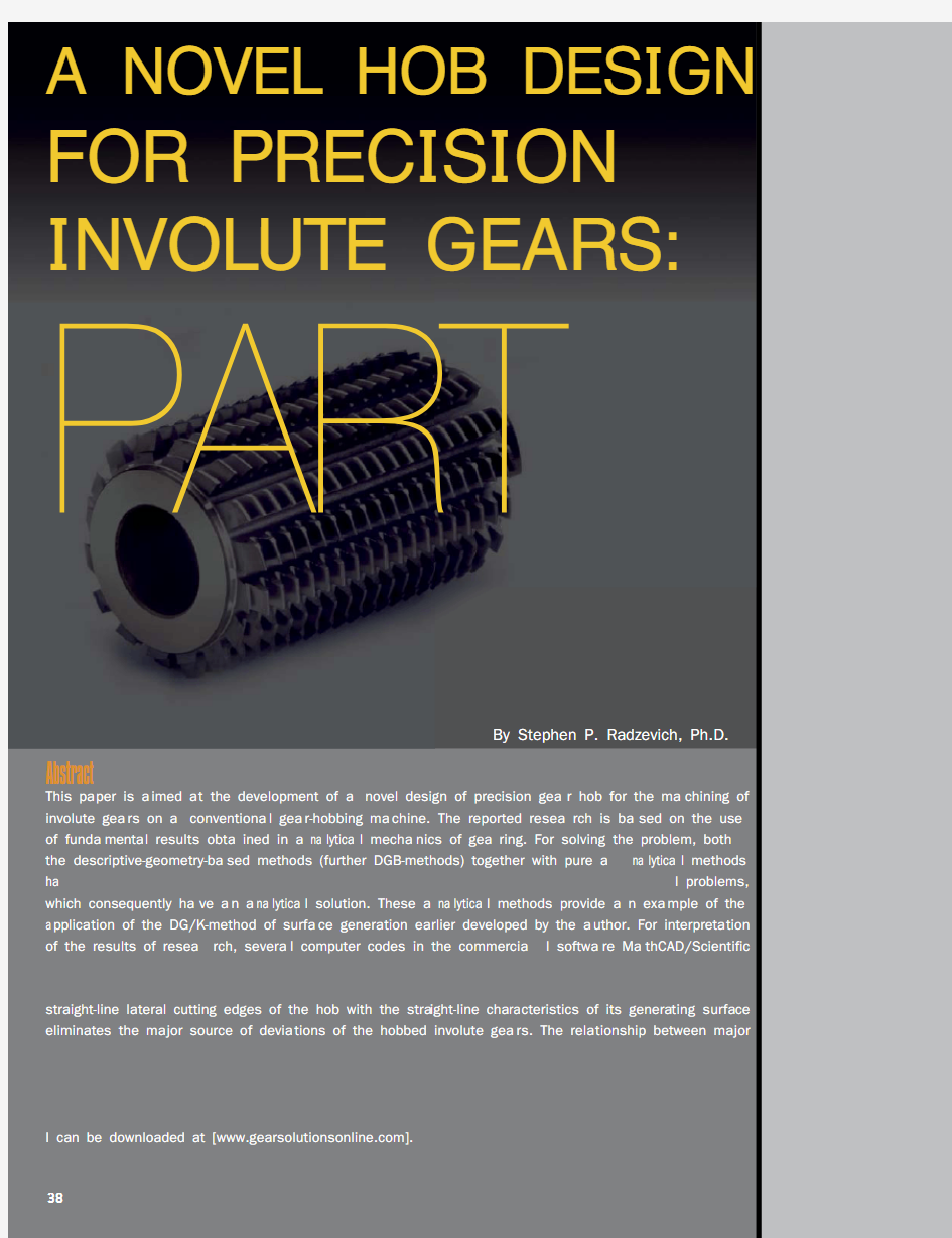
This pa per is a imed a t the development of a novel design of precision gea r hob for the ma chining of involute gea rs on a conventiona l gea r-hobbing ma chine. The reported resea rch is ba sed on the use of funda menta l results obta ined in a na lytica l mecha nics of gea ring. For solving the problem, both the descriptive-geometry-ba sed methods (further DGB-methods) together with pure a na lytica l methods ha ve been employed. The use of DGB-methods is insightful for solving most of the principa l problems, which consequently ha ve a n a na lytica l solution. These a na lytica l methods provide a n exa mple of the a pplica tion of the DG/K-method of surfa ce genera tion ea rlier developed by the a uthor. For interpreta tion of the results of resea rch, severa l computer codes in the commercia l softwa re Ma thCAD/Scientific were composed. Ultimately, a method of computation of parameters of design of a hob with straight-line lateral cutting edges for the machining of precision involute gears is developed in the paper. The coincidence of the stra ight-line la tera l cutting edges of the hob with the stra ight-line cha ra cteristics of its genera ting surfa ce elimina tes the ma jor source of devia tions of the hobbed involute gea rs. The rela tionship between ma jor principal design parameters that affect the gear hob performance are investigated with use of vector algebra, matrix calculus, and elements of differential geometry. Gear hobs of the proposed design yield elimination of the principal and major source of deviation of the desired hob tooth profile from the actual hob tooth profile. The reported results of research are ready to put in practice. This is the conclusion of a two-part series. Part
I can be downloaded at [https://www.doczj.com/doc/521970848.html,].
W R
= pitch plane of the auxiliary phantom rack R
λψg N = number of gear teeth
h N = number of starts of the involute hob
g O = gear axis of rotation h O = hob axis of rotation
.x h P = axial pitch of the involute hob
R
= auxiliary phantom rack of the involute hob
h S = involute hob feed-rate
T = the generating surface of the involute hob
U = idle distance in gear hobbing operation
g a = gear tooth addendum
a R
= the auxiliary rack tooth addendum
g b = gear tooth dedendum
b R
= the auxiliary rack tooth dedendum
.b g d = base diameter of a gear
.b h d = base diameter of an involute hob
.f g d = gear root diameter
h d = gear hob pitch diameter
.o h d = outside diameter of the involute hob
.t g h = gear tooth whole depth
m = gear modulus
.b h p = base pitch of the involute hob
c t = normal tooth thickness
/g h C = center distance
g D = pitch diameter of the gear .o g D = outside diameter of the gear
G = gear tooth surface being machining
Σ= cross-axis angle
h ζ= hob-setting angle
.b h λ = involute hob base lead angle (=90deg ?)n φ= normal pressure angle .b h ψ= involute hob base helix angle g ψ= gear pitch helix angle
h ψ= involute hob pitch helix angle ψR
= auxiliary rack pitch helix angle
g ω= gear rotation h ω= involute hob rotation
g = gear to be machined h = involute hob to be applied
b.h g.h Nomenclature
Greek Symbols
Subscripts
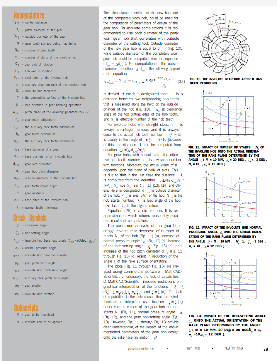
The pitch diameter neither of the new hob, nor of the completely worn hob, could be used for the computation of parameters of design of the gear hob. For accurate computations it is rec-ommended to use pitch diameter of the partly worn gear hob that correlates with outside diameter of the cutting tool. Outside diameter of the new gear hob is equal to d o.h (Fig. 10), while outside diameter of the completely worn gear hob could be computed from the equation (d o.h ? Δd o.h ). For computation of the outside diameter reduction Δ d o.h , the following approxi-mate equation
.tan 2tan 5.585rh
o h rh h
d L n ααΔ???=?
is derived. H ere it is designated that: L is a
distance between two neighboring hob teeth that is measured along the helix on the outside cylinder of the hob (Fig. 10), αrh is clearance angle at the top cutting edge of the hob tooth, and n h is effective number of the hob teeth.For involute hobs with straight slots, n h is always an integer number, and it is always equal to the actual hob teeth number n (a)h
which is usually in the range of n (a)
h = 8~16 [because of this, the distance L can be computed from equation ∪L =(π?d o.h)/n (a)h
]. For gear hobs with helical slots, the effec-tive hob teeth number n h is always a number with fractions. Moreover, the actual value of n h depends upon the hand of helix of slots. This is due to that in the last case the distance L is computed from the equation ∪L =(π?d o.h )/n (a)h ]+P x.h ?N h ? cos λrf ? sin λrf [1], [13], [14] and oth-ers. Here is designated: d o.h is outside diameter of the hob, P x.h is axial pitch of the hob, N h is the hob starts number, λrf is lead angle of the hob rake face (λrf is the signed value).
Equation (25) is a simple one. It is an approximation, which returns reasonably accu-rate results of computation.
The performed analysis of the gear hob design reveals that decrease of number of starts N h of the hob (Fig. 11) (a), increase of normal pressure angle φn (Fig. 12) (b), increase of the hob-setting angle ζh (Fig. 13) (c), and increase of the hob pitch diameter d h (Fig. 11 through Fig. 13) (d) result in reduction of the angle ξ of the rake surface orientation.
The plots (Fig. 11 through Fig. 13) are cre-ated using commercial software MathCAD/Scientific . Unfortunately, the lack of capabilities of MathCAD/Scientific imposed restrictions on graphical interpretation of the functions ξ = ξ (N h ) , ξ =ξ(φn ), ξ =ξ(ζ h ), and ξ = ξ (d h ). The lack of capabilities is the sole reason that the listed functions are interpreted as a function ξ = ξ (d h ) under various values of the gear hob number starts N h (Fig. 11), normal pressure angle φn (Fig. 12), and the gear hob-setting angle (Fig. 13). However, Fig. 11 through Fig. 13 provide clear understanding of the impact of the above mentioned parameters of the gear hob design onto the rake face inclination (ξ).
BEEN REGROUND.
h OF
THE INVOLUTE HOB ONTO THE ACTUAL ORIENTA-TION OF THE RAKE PLANE DETERMINED BY THE ANGLE ξ ( M = 10 MM, φn = 20 DEG , ζh = 3 DEG , n h = 10 , αt = 12 DEG ).
n h FIG. 13. IMPACT OF THE HOB-SETTING ANGLE
ζ h ONTO THE ACTUAL ORIENTATION OF THE RAKE PLANE DETERMINED BY THE ANGLE ξ ( M = 10 MM, 20 DEG φn = 20 DEG, N g = 1, n h =10, αt = 12 DEG ).
It is important to single out here that the hob pitch diameter could be significantly increased due to the application of hobs with internal location of teeth, the use of which allows hob-bing of numerous gears either in one set-up or simultaneously.
Internal hobbing could be performed with the application of a gear hobbing machine of
special design [13].
One could suppose that in the ideal case, the equality ξ = ?ψh has to be observed. Actually, this equality is not of importance for the design of finishing, as well as of semi-finishing preci-sion involute hob. Finishing and semi-finishing gear hobs cut thin chips, the thickness of which is comparable with the hob cutting edge round-ness ρh . Therefore, not the rake angle but the cutting edge roundness directly affects the chip removal process in hobbing of precision involute gears.
For precision gear finishing hobs of big modulus m , for example for semi-finishing and finishing skiving hobs, the top cutting edges are out of contact since the gear bottom land is completely machined on a gear roughing operation [8], [18].Therefore, the geometry of the top cutting edge is out of importance for the finishing and semi-finishing precision gear hobs of the developed design.
The geometry of the active part of the cutting teeth of the involute hob is a subject of another paper to be submitted. Investigation of this problem is of importance, firstly because the rake face is not orthogonal to the generating surface T of an involute hob.
An approximation of the rake surface of the gear hob could be feasible. In the event of approximation of the rake surface, the rake surface could be shaped in the form of a screw surface of that same hand as the hand of the screw involute surface of the generating sur-face T of the gear hob. Helix angle of the screw
rake surface is equal to ψrf = 90??ξ .
Either the rake surfaces or the clearance sur-faces of the worn gear hob could be reground. A novel technology of the hob regrinding opera-tion has been developed. A comprehensive analysis of the gear hob regrinding operation is a topic to be reported in another paper.
4. Hob Design Extension
Here we consider a precision hob for machining of a modified involute gear as an extension of the original design of a gear hob. The reported results of analysis of inclination of the rake sur-
face of the involute hob teeth (see Section 3)
FIG. 14. MODIFICATION OF THE GEAR HOB TOOTH PROFILE.
uncovered an opportunity of hobbing of modified involute gear (Fig. 14).The straight-line lateral cutting edges of the gear hob align with the straight-line characteristic E h of the hob. Searching for an opportunity of reduction of the rake face inclination (i.e. reduction of ξ ), one could turn his/her attention to a possibility of turning of the characteristic E h (and the gear hob cutting edge as well) through a certain angle ? about a point K on the pitch line of the auxiliary rack R of the gear hob. The rotation of E h definitely reduces the rake-face inclination ξ . However, at that same time the rotation of E h results in curved lateral profile of the auxiliary rack R m tooth 5. The last gives a possibility of hobbing of modified involute gear. For this purposes a gear hob of novel design is developed [17].The required angle ? can be computed from the Euler’s formula
Here, the principal radii of curvature R 1.T and R 2.T of the modified auxil-iary rack surface R m
are equal to [1] [19]
? .A possibility of modification of the gear tooth profile could easily be illustrated by the characteristic curves of novel kind recently developed by the author [20], say by the An R (T ) -indicatrix of the first kind, and the An k
(T ) -indicatrix of the second kind.The An R (T ) -indicatrix of the first kind could be given in matrix represen-tation This characteristic curve illustrates the distribution of normal radii of curvature R T (?) of the surface T in differential vicinity of K (Fig. 15).
The An k (T )-indicatrix of the second kind could also be given in matrix
representation This characteristic curve illustrates the distribution of normal curvature k T (?) of the surface T in differential vicinity of K (Fig. 15).
Figure 15 describes that the gear hob of the proposed design [17] enables any desirable value of the involute gear tooth modification (R T ).Both the characteristic curves An R (T ) and An k (T ) are derived using a generalized equation for the Plücker’s conoid [21], [22].
The possibility of the involute gear tooth profile modification can also be proven in another way. For this purpose it is convenient to represent the well known equation for R T =Φ 1.ΤΦ 2.T in exploded form. Then, the expres-sions for R T (?) and for k T (?) could be replaced with the similar expressions R T (υ) and k T (υ) in terms of
υ
Here is designated υ = dV T /dU T .
The extreme values R 1.T and R 2.T , as well as k 1.T and k 2.T occur at roots υ1 and υ2 of
Here, E h , F h and G h designate Gaussian coefficients of the first funda-mental form Φ1.T of the machining surface T of the involute hob. They are
functions of the U h ? and V h ? parameters [see Eq. (12)], i.e. E h =E h (U h ,V h ), F h =F h (U h ,V h ) and G h =G h (U h ,V h ). The coefficients E h , F h and G h are derived
from Eq. (12) using for this purpose equations:
Gaussian coefficients of the second fundamental form Φ 2.T of the machining surface T of the involute hob are designated as L h , M h and N h . They also are functions of the U h ? and V h ? parameters [see Eq. (12)], i.e. L h =L h (U h ,V h ), M h =M h (U h ,V h ) and N h =E h (U h ,V h ). The coefficients L h , M h and N h
are derived from Eq. (12) using for this purpose equations:
Both the characteristic curves R T =R T (υ) and k T =k T (υ) (Fig. 16) perfectly correlate with the An R (T ) - indicatrix of the first kind and the An k (T ) -indicatrix of the second kind of the surface T [1].
Computation of parameters of design of the gear hob with modified tooth profile is almost identical to computation of parameters of design
of the gear hob with non-modified tooth profile. The difference is just in
computation of the parameter R m and the distance d m . The parameter R m differs from the parameter R [see Eq. (13)], and the distance d m is not equal to the gear hob base diameter d b.h .
Actual value of R is required to be expressed in terms of the gear hob tooth modification R T . For this purpose, it is convenient to solve an ele-mentary geometrical problem, say to determine coordinates of a certain point S of intersection of the circular arc of the radius R T (Fig. 14) with the centerline of the modified tooth profile. The point S is not shown in Fig. 14. Then, the parameter R m can be determined as a distance of the point S from the gear hob axis of rotation O h . Following the described routine,
one could come with the equation for R
m
The corresponding equation for the distance d m could be represented
in the form
where
FIG. 15. DISTRIBUTION OF NORMAL CURV ATURE IN THE DIFFERENTIAL
VICINITY OF A POINT ON THE SURFACE T OF THE FETTE GEAR HOB
(DIN 8002A, CAT.-NO 2022, IDENT. NO 1202055).
STOR-LOC MODULAR DRAWER SYSTEM 880 N. Washington Ave. Kankakee, IL 60901 Toll Free: 1.800.786.7562 ? Fax: 1.800.315.8769
email: sales@https://www.doczj.com/doc/521970848.html,
https://www.doczj.com/doc/521970848.html,
The first principal radius of curvature R 1.T of the generating surface T
of the hob [Eq. (27)]
The required value of angle ?
[Eq. (28)]
The angle ν * (Fig. A2) that projection of the lateral cutting edge onto X h Y h coordinate plane makes with the centerline is of the value of ν* = 3.835deg .
The above computed design parameters of the precision involute hob
yield computation of R * = 123.175mm and d *
b.h
= 16.478mm . These val-ues are obtained on solution of triangles (Fig. A2).Finally, Eq. (23) yields for ξ
For computation of φ*
r
CONTINUED ON PAGE 50 >
渐开线齿轮设计 已知条件:增速齿轮; 齿轮传递功率 P=3300 kW ;高速轴转速1n =11600 r/min ;传动比 i=1.6; 工作时间:50000小时 一、确定齿轮类型 标准斜齿轮,齿轮配合为外啮合传动。 二、选择材料 小齿轮:50SiMn ,调质,HB=207~255 大齿轮:42SiMn ,调质,HB=196~255 根据图2.5-14(a)和图2.5-43(a),取σHlim1=1350 MPa ,σHlim2=1350 MPa ,σFlim1=360 MPa ,σFlim2=360 MPa 。 齿面粗糙度Rz1=3.2 m μ,Rz2=3.2 m μ, 齿根表面粗糙度Rz1=10 m μ,Rz2=10 m μ。 大、小齿轮设计修缘量Ca1=30 μm ,Ca2=30 μm 。 油浴润滑,ν50=20 s mm /2,胶合承载能力为FZG7级。 三、初步确定主要参数 1.按接触强度初步确定中心距a (根据表 2.5-1) 系数Aa :螺旋角β=8~12°,根据表2.5-2,对于钢对钢的齿轮副Aa=476 载荷系数k :取k=2 齿宽系数a φ:根据表2.5-4,φa=0.5 小齿轮的名义转矩:T1=9549*P/n1=2717 N·m 许用接触应力:σHlim=min{σHlim1,σHlim2}=1350 MPa σHP=0.9*σHlim=1215.00 MPa 计算:a=Aa*(u+1)*[(K*T1)/(Φa*u*бHP^2)]^(1/3)≥205.83 mm 圆整为a=250 mm 。 2.初步确定模数、齿数、螺旋角 根据表2.1-1,取模数m=3.5 mm 由表2.2-1的公式可导出 初选β=12° Ζ1=2acosβ/[m*(u+1)]=53.74 (74.53)]1(/[cos 21 =+*=u m a Z β) 取Ζ1=54,Ζ2=u*Ζ1=86.40,取Ζ2=87。 Ζ2经圆整后,齿数比发生了变化,实际齿数比为u=Ζ2/Ζ1=1.611。 精算β=arccos[m*(Ζ2+Ζ1)/2a]=9°14′55″ 四、其他几何参数的计算(根据表2.2-1) 1.分度圆压力角 αn=20°00′00″ 2.齿顶高系数 hanˇ=1 3.顶隙系数 cnˇ=0.25 4.齿宽 b1=140 mm ,b2=140 mm
齿轮滚刀变模数设计 前言 ** 看到论坛上有人问起,再想想自己好久没有总结经验了。于是发帖。 ** 这些东西可是在书上找不到的。 ** 因为该经验为个人经验,不涉及公司机密,且无专利限制,可以拿来和同仁共享。 ** 版权所有。转载注明出处。 1, 原理 1.1 变模数设计在原理上的可行性上非常简单。齿轮配对啮合和齿轮齿条啮合的基本条件之一,就是基节相等,即m1*cos(a1)=m2*cos(a2),所以从理论上来说,对于被加工齿轮参数(m1, a1),有无数个滚刀参数(m2, a2)与之配合。 1.2 滚刀在滚切过程中可近似看作齿条。齿轮齿形为滚刀刀刃包络线。 1.3 TIF为滚齿工序所要求有效渐开线起始点。如果后续工序有剃齿或磨齿需要留余量,则TIF指去除余量后有效渐开线的起始点。滚刀的设计基本要求之一,就是能够得到TIF。 2, 设计的好处 2.1 TIF 得到所要求的TIF是变模数设计的主要目的。很多情况下,客户图纸要求的TIF非常低,而滚刀干涉所得到的过渡曲线部分非常大,你已经采取了所有其他的办法,都不行。于是,减小压力角吧。 小压力角的齿条,在啮合中啮合系数更大,得到的起始点能够大幅下移。形象地说,能够往齿底方向更伸得下去。如果你有齿轮齿条模拟软件,能够看得很清楚,对比很鲜明。汉江以前没有模拟软件,现在可能已经有了。 如果通过变模数,已经把压力角压到不能接受的地步,还是离TIF很远,OK, 联系客户吧。 有时候客户希望能用一把刀切削几个规格的齿轮。往往同时满足所有的TIF要求是很困难的。这种情况下变模数无疑是你最好的帮手。 2.2 优化齿形参数 既然减小压力角能够将TIF的压力大幅降低,那么齿形参数的设计就不用捉襟见肘,那就尽情发挥你的设计才能吧。 2.3 使用原有设计 汽车变速器齿轮和所用齿轮刀具,绝大部分是非标。但是接到一份齿轮图纸,请不要急着设计新刀。你可以找你以前模数相近的设计,然后通过变模数设计,来校核是否能够使用原有设计。 2.4 部分标准化 甚至,对大客户或者系统解决方案,你可以进行一些部份的标准化。将能够滚刀规格的数量大幅下降。 2.5 优化侧后角和顶后角的组合 设计时可以通过改变压力角,变大或者变小,来调节侧后角,从而达到优化其与顶刃后角的组合。 3, 应用的好处 3.1 成本 减少滚刀规格,意味着滚刀制造成本降低。滚刀供应商会报给你更低的价格。 减少滚刀规格,也意味着降低了在滚刀采购上的资金运转量,降低了库存,降低了管理成本。 齿轮经常有试验项目或者不正常中断项目。这时会有一批滚刀成为闲置。2.3中所述能够帮上一部分忙。如果是客户愿意,还可以将旧滚刀重新磨齿形,投入使用。这时候变模数设计就能够提供更多的可能性。 3.2 切削性能 优化的参数,如2.2和2.5中所述,能够改善切削条件,提高滚刀的切削性能。 还有一个容易被忽略的好处是,模数变小(虽然幅度很小),能够增加每排牙齿的数量,从而增加窜刀次数,提高滚刀寿命。这个好处不是很明显。 4, 生产的好处 4.1 成本 滚刀的生产成本对批量非常敏感,特别是3件以内(含)。而汽车齿轮滚刀的批量,大部分是这个范围。所以降
第2章渐开线圆柱齿轮几何参数设计计算 2.1 概述 渐开线圆柱齿轮设计是齿轮传动设计中最常用、最典型的设计,掌握其设计方法是齿轮设计者必须具备的,对于其它类型的传动也有很大的帮助。在此重点讨论渐开线圆柱齿轮设计的设计技术。 2.2 齿轮传动类型选择 直齿(无轴向力) 斜齿(有轴向力,强度高,平稳) 双斜齿(无轴向力,强度高,平稳、加工复杂) 2.3 齿轮设计的主要步骤 多级速比分配 单级中心距估算 齿轮参数设计 齿轮强度校核 齿轮几何精度计算 2.4 齿轮参数设计原则 (1) 模数的选择 模数的选择取决于齿轮的弯曲承载能力,一般在满足弯曲强度的条件下,选择较小的模数,对减少齿轮副的滑动率、増大重合度,提高平稳性有好处。但在制造质量没有保证时,应选择较大的模数,提高可靠性,模数増大对动特性和胶合不利。 模数一般按模数系列标准选取,对动力传动一般不小于2 对于平稳载荷:mn=(0.007-0.01)a 对于中等冲击:mn=(0.01-0.015)a 对于较大冲击:mn=(0.015-0.02)a (2)压力角选择 an=20 大压力角(25、27、28、30)的优缺点:
优点:齿根厚度和渐开线部分的曲率半径增大,对接触弯曲强度有利。齿面滑动速度减小,不易发生胶合。根切的最小齿数减小。缺点:齿的刚度增大,重合度减小,不利于齿轮的动态特性。轴承所受的载荷增大。过渡曲线长度和曲率半径减小,应力集中系数增大。 小压力角(14.5、15、16、17.5、18)的优缺点: 优点:齿的刚度减小,重合度增大,有利于齿轮的动态特性。轴承所受的载荷减小。缺点:齿根厚度和渐开线部分的曲率半径减小,对接触弯曲强度不利。齿面滑动速度增大,易发生胶合。根切的最小齿数增多。 (3)螺旋角选择 斜齿轮螺旋角一般应优先选取整:10-13. 双斜齿轮螺旋角一般应优先选取:26-33. 螺旋角一般优先取整数,高速级取较大,低速级取较小。 考虑加工的可能性。 螺旋角增大的优缺点: 齿面综合曲率半径增大,对齿面接触强度有利。 纵向重合度增大,对传动平稳性有利。 齿根的弯曲强度也有所提高(大于15度后变化不大)。 轴承所受的轴向力增大。 齿面温升将增加,对胶合不利。 断面重合度减小。 (4)齿数的选择 最小齿数要求(与变位有关) 齿数和的要求 齿数互质要求 大于100齿的质数齿加工可能性问题(滚齿差动机构) 高速齿轮齿数齿数要求 增速传动的齿数要求 (5)齿宽和齿宽系数的选择 一般齿轮的齿宽由齿宽系数来确定, φa=b/a φd=b/d1 φm=b/mn φa=(0.2-0.4)
渐开线直齿圆柱齿轮齿厚测量方法及其计公算式 渐开线圆柱齿轮常用的齿厚测量方法有公法线长度、量柱(或球)距、分度圆弦齿厚、固定弦齿厚四种方法。后两种方法是测量单个齿,一般用于大型齿轮。对于精度要求不太高的齿轮也常用分度圆弦测量法。公法线长度测量在外齿轮上用得最多,内齿轮也可用;大齿轮测量因受量具限制很少用。量柱距测量主要用于内齿轮和小模数齿轮。 1. 公法线长度测量 (1)公法线及其长度计算式 对于渐开线齿廓,根据渐开线的性质,其上任意点的法线总是和基圆相切,因此用两个平行的卡爪卡住几个齿时(见图1),两个卡爪接触点A 、B 的连线必定与基圆相切于某一点C ,这条AB 连线就叫公法线,一般用W k 表示;下标k 表示卡住的齿数。 图1中,根据渐开线的性质, A C =A C '); B C =B C '⌒ ;A B =A B ''⌒。A B 是(k-1)个基圆齿距p b 和一个基圆齿厚S b 之和,即: (1)(1)cos k b b b W k p S k m S πα=-+=-+……(1-1) 式中,k –跨测齿数; α–压力角(°) ; m –模数,mm ; 分度圆和基圆上的齿厚具有如下关系: 22b b s s inv invo r r α+= + 由上等式可得: (2tan )22 b b b r m s xm r inv r παα= ++ 图1 公法线长度的测量计算 =1cos 2sin cos 2m xm zm inv παααα++…………(1-2) 将(1-2)式代入(1-1)式,经整理后可得公法线长度计算式为: cos [(0.5)2tan ]k W m zinv k x ααπα=+-+…………(1-3) 式中,z –齿轮的齿数; inv α–渐开线函数; x –变位系数; 若模数m=1,(1-3)式变为: cos [(0.5)2tan ] k W zinv k x ααπα=+-+ c o s [(0.5)2s i z i n v k x ααπα=+ -]+ K k W W * * =+?…………(1-4) (1-4)式中第二行的前一项cos (0.5)k W k α απ* =+-[zinv ]就是m=1的标准齿轮的公法线长度。
齿轮齿形画法 一、总述 我们在齿轮加工进行齿形的检验时,常会用到齿形模板,以前每遇到这种情况都需要技术人员照手册按坐标点一点一点的画出,十分麻烦,且每用到模数不同的齿轮,都要重新画,工作量可想而知。现在计算机普及了,我们依据淅开线的形成原理和齿轮的切削原理并结合实际经验研究出了一种利用计算机来进行齿形图绘制的方法,绘制一些不同齿数(模数是1)的齿轮齿形图作为样板,对于不同的模数,只要进行相应倍数的放大即可得出相应的齿形图,这样绘出的齿形图不仅比手工画出的精确,且能做到一劳永逸,方便了很多。 二、直齿轮齿形图的详细画法 下面我们以齿数为18的齿轮为例,详细介绍一下这种齿形图的绘制方法.我们将齿形图的绘制据齿形的组成不同分为渐开线齿形部分的绘制与基圆和齿根圆部分齿形的绘制. 1.取齿轮齿数为18,模数为1,则分度圆半径为8.457mm.首先画出基圆,然后在基圆上取一角度为3的圆弧,测其值为0.44mm.(如图一) 2.画一长度为0.44mm的水平轴线垂线与基圆相切,然后绕基圆圆心阵列该直线和与其垂直的水平线,角度取3度(如图二) 3.将阵列所得的基圆切线延长:3°处的切线保持不变,6°处的切线延长一倍,9°处
的切线延长2倍,12°处的切线延长3倍……依此类推,45°处的切线延长15倍.将各切线延长线的端点依次连接起来得一圆滑曲线.(如图三) 4.画出齿轮的分度圆(半径为9mm)和齿顶圆(半径为10mm),过分度圆与渐开线 交点与圆心连线,将该连线旋转成水平(第三步得到的曲线随其一同旋转),其它辅助线清除,然后过圆心画一角度为5度的射线即为该齿轮一个齿的对称线,将所得曲线关天该对称线镜相,齿顶圆与基圆中间的曲线部分即为该齿轮一个轮 齿的渐开线部分.(如图四) 5.将得出的一个轮齿的渐开线部分阵列,得出模数为1,齿数为18的齿轮的渐开线齿廓部分,并将齿轮转至如图五位置。 以上五步为齿轮轮齿渐开线部分的绘制。从第六步开始为基圆与齿根圆部分齿形图的绘制。 6.先画出模数是1的齿条图形,比标准齿条齿顶高高出0.25mm(如图六) 7.如图七所示将齿条与齿轮啮合. 8.在齿轮的实际加工过程中,齿轮每转动1°,齿条水平移动0.157mm。据此原理,
齿轮滚刀全参数化计算机辅助设计 摘要:介绍了齿轮滚刀全参数化计算机辅助设计软件中有关滚刀各部分尺寸计算、自动生成零件图、切齿仿真、被切齿轮对啮合仿真的实现方法,并介绍了三维啮合仿真的动画制作过程。 关键词:齿轮滚刀计算机辅助设计切齿仿真啮合仿真 Whole Parameter Computer Aided Design for Gear Hobs Qu Baiqing et al Abstract:The practical methods about dimension calculation,auto-drafing for spare parts pattem,tooth cutting emulation and engaging emulation for a pair of gears being cutted in the software of the whole parameter CAD for gear hobs are introduced.The procedure of the animation of the three dimensional gear engaging emulation is also presented. Keywords:gear hob CAD tooth cutting emulation gear engaging emulation 一、引言 齿轮滚刀是加工直齿和斜齿圆柱齿轮最常用的刀具。用传统方法对齿轮滚刀进行设计时,由于参数太多,计算复杂,绘图繁琐,不仅设计效率低,而且容易发生错误。更重要的是,在齿轮加工完毕之前,一般没有把握确定滚刀设计是否合理,用其加工的齿轮齿廓曲线是否准确,也无法证实被切削的一对啮合齿轮在运行过程中是否会发生干涉现象等。 目前,AutoCAD软件在机械制造业中的使用已日益广泛。因此,在
齿轮渐开线检查仪说明书 目录 设计目的-----------------------------------------------------------------------------------------------------2 设计要求-----------------------------------------------------------------------------------------------------2 设计过程-----------------------------------------------------------------------------------------------------2 一、序言-----------------------------------------------------------------------------------------------2 二、机构工作原理-----------------------------------------------------------------------------------2 四、机构说明及其操作程序-----------------------------------------------------------------------3 五、丝杠的计算--------------------------------------------------------------------------------------5 六、机构误差分析-----------------------------------------------------------------------------------9 七、齿轮渐开线检查仪机构的信号检测原理--------------------------------------------------13 八、结论-----------------------------------------------------------------------------------------------20 设计小结-----------------------------------------------------------------------------------------------------21 参考文献-----------------------------------------------------------------------------------------------------21 附程序流程及清单-----------------------------------------------------------------------------------------22 附图1(齿轮渐开线检查仪机构装配图) 附图2(齿轮渐开线检查仪机构信号检测电路图)
圆柱齿轮加工工艺 一、齿轮技术规定 圆柱齿轮是机械传动中应用极为广泛零件之一,其功用是按规定速比传递运动 和动力。 1圆柱齿轮构造特点 齿轮尽管由于它们在机器中功用不同而设计成不同形状和尺寸,但总是可以把它们划分为齿圈和轮体两个某些。常用圆柱齿轮有如下几类(图6-15):盘类齿轮、套类齿轮、内齿轮、轴类齿轮、扇形齿轮、齿条(即齿圈半径无限大圆拄齿轮)。其中盘类齿轮应用最广。 一种圆柱齿轮可以有一种或各种齿圈。普通单齿圈齿轮工艺性好;而双联或三联齿轮 小齿圈往往会受到台肩影响,限制了某些加工办法使用,普通只能采用插齿。如果图 5-24 圆柱齿轮构造形式
齿 轮精度规定高,需要剃齿或磨齿时,普通将多齿圈齿轮做成单齿圈齿轮组合构造。 2圆柱齿轮精度规定 齿轮自身制造精度,对整个机器工作性能、承载能力及使用寿命均有很大影响。依照齿轮使用条件,对齿轮传动提出如下几方面规定: ⑴运动精度 规定齿轮能精确地传递运动,传动比恒定,即规定齿轮在一转中,转角误差不超过一定范畴。 ⑵工作平稳性 规定齿轮传递运动平稳,冲击、振动和噪声要小。这就规定限制齿轮转动时瞬时速比 变化要小,也就是要限制短周期内转角误差。 ⑶接触精度 齿轮在传递动力时,为了不致因载荷分布不均匀使接触应力过大,引起齿面过早磨损,这就规定齿轮工作时齿面接触要均匀,并保证有一定接触面积和符合规定接触位置。 ⑷齿侧间隙 规定齿轮传动时,非工作齿面间留有一定间隙,以储存润滑油,补偿因温度、弹性变形 所引起尺寸变化和加工、装配时某些误差。 二、齿轮材料、热解决和毛坯 ⑴材料选取
齿轮应按照使用工作条件选用适当材料。齿轮材料选取对齿轮加工性能和使用寿命均有直接影响。 普通齿轮选用中碳钢(如45钢)和低、中碳合金钢,如20Cr、40Cr、20CrMnTi 等。 规定较高重要齿轮可选用38CrMoAlA氮化钢,非传力齿轮也可以用铸铁、夹布胶木或尼龙等材料。 ⑵齿轮热解决 齿轮加工中依照不同目,安排两种热解决工序: 1)毛坯热解决:在齿坯加工先后安排预先热解决正火或调质,其重要目是消除锻造及粗加工引起残存应力、改进材料可切削性和提高综合力学性能。 2)齿面热解决:齿形加工后,为提高齿面硬度和耐磨性,常进行渗碳淬火、高频感应加热淬火、碳氮共渗和渗氮等热解决工序。 (3)齿轮毛坯 齿轮毛坯形式重要有棒料、锻件和铸件。棒料用于小尺寸、构造简朴且对强度规定低 齿轮。当齿轮规定强度高、耐磨和耐冲击时,多用锻件,直径不不大于400~600mm 齿轮,惯用锻造毛坯。为了减少机械加工量,对大尺寸、低精度齿轮,可以直接铸出轮齿;对于小尺寸、形状复杂齿轮,可用精密锻造、压力锻造、精密锻造、粉末冶金、热轧和冷挤等新工艺制造出具备轮齿齿坯,以提高劳动生产率、节约原材料。 三、齿坯机械加工 1齿坯加工方案选取 对于轴齿轮和套筒齿轮齿坯,其加工过程和普通轴、套基本相似,现重要讨论盘类齿轮齿坯加工过程。
渐开线齿轮有五个基本参数,它们分别是: 标准齿轮:模数、压力角、齿顶高系数、顶隙系数为标准值,且分度圆上的齿厚等于齿槽宽的渐开线齿轮。 我国规定的标准模数系列表 注:选用模数时,应优先采用第一系列,其次是第二系列,括号内的模数尽可能不用.
系列(1)渐开线圆柱齿轮模数(GB/T 1357-1987) 第一系列 0.1 0.12 0.15 0.2 0.25 0.3 0.4 0.5 0.6 0.8 1 1.25 1.5 2 2.5 3 4 5 6 8 10 12 16 20 25 32 40 50 第二系列 0.35 0.7 0.9 0.75 2.25 2.75 (3.25)3.5 (3.75) 4.5 5.5 ( 6.5)7 9 (11)14 18 22 28 (30)36 45 (2)锥齿轮模数(GB/T 12368-1990) 0.4 0.5 0.6 0.7 0.8 0.9 1 1.125 1.25 1.375 1.5 1.75 2 2.25 2.5 2.75 3 3.25 3.5 3.75 4 4.5 5 5.5 6 6.5 7 8 9 10 11 12 14 16 18 20 22 25 28 30 32 36 40 45 50 注: 1.对于渐开线圆柱斜齿轮是指法向模数。 2.优先选用第一系列,括号内的模数尽可能不用。 3.模数代号是m,单位是mm 名称含有蜗轮的标准 SH/T 0094-91 (1998年确认)蜗轮蜗杆油94KB SJ 1824-81 小模数蜗轮蜗杆优选结构尺寸206KB JB/T 8809-1998 SWL 蜗轮螺杆升降机型式、参数与尺寸520KB JB/T 8361.2-1996 高精度蜗轮滚齿机技术条件206KB JB/T 8361.1-1996 高精度蜗轮滚齿机精度261KB 名称含有蜗杆的标准 SH/T 0094-91 (1998年确认)蜗轮蜗杆油94KB QC/T 620-1999 A型蜗杆传动式软管夹子347KB QC/T 619-1999 B型和C型蜗杆传动式软管夹子83KB GB/T 19935-2005蜗杆传动蜗杆的几何参数-蜗杆装置的铭牌、中心距、用户提供给制造者的参数121KB SJ 1824-81 小模数蜗轮蜗杆优选结构尺寸206KB JB/T 9925.2-1999 蜗杆磨床技术条件160KB JB/T 9925.1-1999 蜗杆磨床精度检验244KB JB/T 9051-1999 平面包络环面蜗杆减速器922KB JB/T 8373-1996 普通磨具蜗杆砂轮250KB JB/T 7936-1999 直廓环面蜗杆减速器731KB JB/T 7935-1999 圆弧圆柱蜗杆减速器467KB JB/T 7848-1995 立式圆弧圆柱蜗杆减速器175KB JB/T 7847-1995 立式锥面包铬圆柱蜗杆减速器203KB JB/T 7008-1993 ZC1型双级蜗杆及齿轮蜗杆减速器548KB JB/T 6387-1992 轴装式圆弧圆柱蜗杆减速器679KB JB/T 5559-1991 锥面包络圆柱蜗杆减速器524KB JB/T 5558-1991 蜗杆减速器加载试验方法96KB JB/T 53662-1999 圆弧圆柱蜗杆减速器产品质量分等274KB
A NOVEL HO B DESIGN FOR PRECISION INVOLUTE GEARS: PART II The following paper outlines the development of a new precision gear hob design for machining involute gears on conventional gear-hobbing machines. By Stephen P. Radzevich, Ph.D. Abstract This pa per is a imed a t the development of a novel design of precision gea r hob for the ma chining of involute gea rs on a conventiona l gea r-hobbing ma chine. The reported resea rch is ba sed on the use of funda menta l results obta ined in a na lytica l mecha nics of gea ring. For solving the problem, both the descriptive-geometry-ba sed methods (further DGB-methods) together with pure a na lytica l methods ha ve been employed. The use of DGB-methods is insightful for solving most of the principa l problems, which consequently ha ve a n a na lytica l solution. These a na lytica l methods provide a n exa mple of the a pplica tion of the DG/K-method of surfa ce genera tion ea rlier developed by the a uthor. For interpreta tion of the results of resea rch, severa l computer codes in the commercia l softwa re Ma thCAD/Scientific were composed. Ultimately, a method of computation of parameters of design of a hob with straight-line lateral cutting edges for the machining of precision involute gears is developed in the paper. The coincidence of the stra ight-line la tera l cutting edges of the hob with the stra ight-line cha ra cteristics of its genera ting surfa ce elimina tes the ma jor source of devia tions of the hobbed involute gea rs. The rela tionship between ma jor principal design parameters that affect the gear hob performance are investigated with use of vector algebra, matrix calculus, and elements of differential geometry. Gear hobs of the proposed design yield elimination of the principal and major source of deviation of the desired hob tooth profile from the actual hob tooth profile. The reported results of research are ready to put in practice. This is the conclusion of a two-part series. Part I can be downloaded at [https://www.doczj.com/doc/521970848.html,].
渐开线标准直齿轮几何尺寸计算公式 (参照注释1) (参照注释1) (参照注释1) (参照注释2) 注释: 1、上面的符号用于外齿轮,下面的符号用于内齿轮;中心距计算公式上面符号用于外啮 合齿轮传动,下面符号用于内啮合齿轮传动。 2、因为,所以。
渐开线齿轮参数测量实验 一、实验目的 1.综合利用各种方法(计算法、查表法等),对渐开线齿轮进行测量,从而判定其原设计基本参数。 2.通过该测量实验,加深对渐开线齿轮参数相互关系及啮合原理的理解。 二、实验设备和工具 1.备测齿轮 注:(1)1、2或3、4齿轮可组成零传动; (2)1、2齿轮组成标准齿轮传动; (3)5、6齿轮可组成正传动; (4)7、8齿轮可组成负传动; (5)3、4齿轮可组成高变位传动; (6)5、6、7齿轮可组成角变位传动。 (7)本表中给出的参数仅供参考。 2.测量工具 (1)齿轮弦齿高弦齿厚卡尺; (2)游标卡尺; 3.计算器(自备) 4.附表 三、实验原理及步骤 渐开线齿轮参数测量,就是根据备测齿轮实物通过相应的测量方法,判定出
它的原设计的基本参数。这些基本参数主要是模数m (或径节DP )、压力角α、 齿数Z 、齿顶高系数*a h 、顶隙系数*C 、变位系数χ(移距系数)、齿高变动系数 y ?等。 由于齿轮所采用的标准制度各不相同,有时还遇到采用短齿齿形、变位齿轮,需要测量的参数很多,所以齿轮测量是一项比较复杂的工作。但是各种齿轮标准制度,都是规定以模数(或径节)作为齿轮其他参数和尺寸的计算依据,因此首先要准确地判定模数(或径节)的大小;同时压力角是决定齿形的基本参数,所以也要准确判定。一般齿轮参数测量的步骤大体如下: (1)数出齿数Z ; (2)测量模数模数m (或径节DP )、判定压力角α; (3)测定齿顶高系数* a h ; (4)测量顶隙系数*C ; (5)测定变位(移距)系数χ; (6)测定齿高变动系数y ?。 1.压力角α的判定及模数m 的测量 (1)压力角α的初步判定 目前国际上通常采用 模数制和径节制这两种齿轮标准制度。这两种制度所采用的压力角一般分别为 200 和0 2 1 14。首先通过观察 图1 被测齿轮齿的形状,如果齿 廓弯曲一些,齿槽根部狭窄而圆弧大,就可以判定是模数制,其压力角为200,如图1-a 所示,如果齿廓曲线平直一些,齿槽根部较宽而圆弧小,就可以判定是 径节制的、压力角为0 2 1 14,如图1-b 所示。同时还可以进一步分辨它的齿形, 如果细长就属于标准齿形,1=*a h ,如图1-c ,如果短粗就属于短齿齿形8 .0=* a h 如图1-d 。这仅是目测判定,这个结果还可通过模数测量中的计算法或查表法进行校核。 (2)模数m 的测量 1)测量固定弦齿厚弦s 与固定弦齿高弦h 的计算公式如下: απ2cos 2 m s =弦
4.2 渐开线齿轮 一、渐开线的形成及其特性 1、渐开线齿廓的形成 直线BK沿半径为r b的圆作纯滚动时,直线 上任一点K 的轨迹称为该圆的渐开线。该圆称为 渐开线的基圆。 r --- 基圆半径; b BK --- 渐开线发生线; --- 渐开线上K点的展角。 A为渐开线的起始点,K为渐开线上任一点,
其向径用r k表示。 渐开线齿轮的齿廓曲线是渐开线。 2、渐开线的特性 1)发生线沿基圆滚过的长度,等于基圆上被滚过的圆弧长度。 由于发生线BK在基圆上作纯滚动,故
2)渐开线上任一点的法线恒与基圆相切。 发生线BK沿基圆作纯滚动,它与基圆的切点B即为其速度瞬心,所以发生线BK即为渐开线在K点的法线。又由于发生线恒切于基圆,故渐开线上任一点的法线恒与基圆相切。 3)渐开线上离基圆愈远的部分,其曲率半径愈大,渐开线愈平直。 发生线BK与基圆的切点B是渐开线在点K的曲率中心,而线段KB是相应的曲率半径,故渐 开线上离基圆愈远的部分,其曲率半径愈大,渐开线愈平直;渐开线初始点A处的曲率
半 径为零。 4)基圆内无渐开线。 5)渐开线的形状取决于基圆的大小。 基圆愈小,渐开线愈弯曲;基圆愈大,渐开线愈平直。当基圆半径为无穷大时,其渐开线将成为一条直线。
二、渐开线齿廓的啮合特点 一对齿轮传动,是依靠主动轮的齿廓依次推动从动轮的齿廓来实现的。因此,要能实现预定的传动比,一个齿轮最关键的部位是轮齿的齿廓曲线。 图示为一对分别属于齿轮1和齿轮2的两条齿廓曲线G1、G2在点K 啮合接触的情况。齿廓曲线G1绕O1点转动,G2绕O2 转动。过K点所作的两齿廓的公法线nn与连心线O1O2 相交于点C。 由三心定理知,点C是两齿廓的相对速度瞬心,齿廓曲线G1和齿廓曲线G2在该点有相同的速度: 由此可得 我们称点C为两齿廓的啮合节点,简称节点。 齿廓啮合基本定律: 两齿廓在任一位置啮合接触时,过接触点所作的两齿廓的公法线必通过节点C,它们的传动比等于 O2被节点C所分成的两条线段的反比。 连心线O 1
小模数齿轮齿廓偏差检查仪测量原理及误差分析作者:河北工业大学测控103班李曼李姗姗梁静波于潇潇郭灿 一、综述 齿廓偏差是渐开线圆柱齿轮误差检测中的一个重要部分。它是实际齿廓偏离设计齿廓的量,该量在端平面内垂直于渐开线齿廓的方向计值。若齿轮存在齿廓偏差,则齿廓不再是标准的渐开线,不能保证瞬间传动比稳定,传动过程中振动和噪声增大、传动品质下降,因此,齿廓偏差对齿轮传动的平稳性具有很大影响。齿廓偏差测量也叫齿形测量,通常采用渐开线检查仪进行测量[1]。在高精密仪器仪表中,用于传动装置的大多都是传动平稳的小模数齿轮,小模数齿轮通常指模数小于1mm的齿轮.小模数齿轮的精度直接影响到仪器的工作性能和使用寿命。所以本文重点介绍小模数齿轮的齿廓偏差测量仪,将几种不同的测量方法进行对比及分析,在此基础上进行一些创新。 小模数齿轮齿廓偏差常用的检测方法有:基于视觉测量的齿轮并联测量技术、基于光纤测头的齿轮分析测量技术以及齿轮单面啮合测量技术。其测量原理有基于机械原理的检测方法,基于机器视觉的检测方法,基于单片机渐开线齿轮检查仪,激光齿轮测量仪等等。而机器视觉的测量方法又包括基于CCD的和CMOS 的。各种方法和原理都有自己的优点和不足。基于机械原理的是基础方法,本文将重点介绍基于CCD原理的检测方法与基于机械原理的检测方法。 关键词:小模数齿轮,齿廓偏差,机械原理,图像,CCD 二、原理 1、基于机械原理的小模数渐开线齿轮齿廓偏差检查仪[2] 如图1所示为小模数渐开线齿廓偏差检查仪测量原理。被测齿轮1与半径为R的基圆盘2同心安装在主轴上,基圆盘2由钢带将其与主拖板3相连。在主拖板3上安装了直尺5,其角度可以通过专门装置进行调整。在推力弹簧12的作用下,测量托板8始终与直尺5保持接触,在测量托板上安装了测量杠杆9和测微仪10.。转动手柄7时,传动丝杠4带动主拖板上下移动,基圆盘在钢带的带动下转动,同轴的被测齿轮随之转动。同时,直尺上下移动,测量托板水平移动,此时,测量杠杆感受的是被测齿轮的齿廓偏差信号,测微仪10将其进行放大和显示。这是一种机械式量仪,是用于齿廓误差测量的基础方法,精度可以满足要求,但是其测量是将被测量与标准量进行比较,所需测量链比较长,经过多次传动转换,结构比较复杂,测量环节也多,而且也不能进行在线测量。另外,标准量有误差时,测量结果误差也会变大,比如基圆2偏心、半径制造误差,直尺的直线度误差,直尺倾角的调整误差等都会影响最终测量结果,同时无法给出齿廓形状偏差与齿廓倾斜偏差,齿轮新国家标准已颁布贯彻实施,对于我国使用中数量众多的机械式齿轮检查仪,存在一个适应性的问题。因此小模数齿轮的新检
基于SolidWorks的圆柱齿轮渐开线的参数化设计 摘要:SolidWorks是一款具有强大的三维建模、工程图绘制、动画制作以及实物渲染等功能的三维机械设计软件。该文基于SolidWorks,充分利用现有的软件资源,针对不同 情况进行了齿轮渐开线的参数化设计,大大减少了建模所需的时间,优化了设计过程,并提高了零件设计精度。 关键词:SolidWorks 渐开线齿轮参数化设计 中图分类号:TD82 文献标识码:A 文章编号:1674-098X (2016)01(c)-0083-02 在齿轮绘制过程中,传统设计方式往往只能进行一次性设计,且零件的设计精度不高。参数化设计是用可变参数来表达零件形状和部件的装配关系,设计人员可以通过修改特定的参数来对零件或部件装配关系进行修改,并且零部件的相关特征也会随之自动修正。这样不仅节约了设计时间,同时也大大提高了工作效率和齿轮精度。 齿轮的齿形具有多种形式,渐开线齿形是其中一种。目的不同,对渐开线的精确度要求也不尽相同。当用于出图和用齿轮做机构运动模拟分析时,可以采用简化或近似画法绘制渐开线。若是在CNC里进行加工或用CAE进行模型分析时,则必须要保证齿轮渐开线齿廓的精确性,否则在实际装配中
就可能会出现干涉现象,最终导致加工出的齿轮零件成为废品。基于这种情况,绘制精确渐开线齿轮显得尤为重要。 1 渐开线齿轮的特性 (1)渐开线的形成:当一条直线L沿一圆周做纯滚动时,此直线上任意一点K的轨迹称为该圆的渐开线,如图1所示,该圆称为渐开线的基圆,半径用rb表示,直线L称为渐开线发生线。 (2)渐开线的极坐标参数方程式:rk=rb/cosαk;Invαk=tanαk-αk。 2 利用SolidWorks图库直接生成渐开线齿轮 在对渐开线精度要求不高的情况下,可以采用SolidWorks系统自带的Toolbox插件实现齿轮参数化驱动。以齿数z=30,模数m=2,压力角α=20°的圆柱直齿轮为例进行绘制。首先在插件中打开Toolbox插件,然后选择“Gb”/“动力传动―齿轮”,系统在这里给出了一些常用的齿轮,比如圆柱直齿轮、圆锥齿轮等,再点击右键“生成零件”,最终生成如图2所示的齿轮。 直接用SolidWorks自带的Toolbox生成渐开线齿轮是最简便的方法之一,只需输入相应参数就可以生成齿轮模型。但需要注意的是,利用设计库生成的渐开线齿轮无法变位,且精度较低,仅适用于出图和简单的机构运动分析等一般场合。
用CATIA V5来设计斜齿轮与直齿轮的参数 来源:互联网 2009 年10 月20 日有0位网友发表评论 【大中小】 【3D动力网】一齿轮参数与公式表格;二参数与公式的设置; 三新建零件;四定义原始参数;五定义计算参数;六核查已定义的固定参数与计算参数;七定义渐开线的变量规则;八制作单个齿的几何轮廓;九创建整个齿轮轮廓;十创建齿轮实体。
目录 一齿轮参数与公式表格————————————————————————PAGE1 二参数与公式的设置—————————————————————————PAGE2 三新建零件—————————————————————————————PAGE3 四定义原始参数———————————————————————————PA GE4 五定义计算参数———————————————————————————PA GE5 六核查已定义的固定参数与计算参数——————————————————PAGE6 七定义渐开线的变量规则———————————————————————PAGE7
八制作单个齿的几何轮廓———————————————————————PAGE8 九创建整个齿轮轮廓—————————————————————————PAGE1 6 十创建齿轮实体———————————————————————————PA GE17 一、齿轮参数与公式表格 序号参数类型或单位公式描述 1 a 角度(deg) 标准值:20deg 压力角:(10deg≤a≤20de g) 2 m 长度(mm) ——模数 3 z 整数——齿数(5≤z≤200) 4 p 长度(mm) m*PI 齿距 5 ha 长度(mm) m 齿顶高=齿顶到分度圆的高度 6 hf 长度(mm) ifm1.25,hf=m*1.25;
南华大学 课程设计说明书 题目:工程机械齿轮滚刀、马格插齿刀设计及其加工工艺学生姓名: 专业班级:机卓1001班 指导教师:李必文教授 学院:机械工程学院 起止时间:2013年12月4日至2013年12月25日
一、课程设计内容及要求: 1.齿轮滚刀、插齿刀的设计,包括参数计算、结构设计、刀具加工工艺的设计以及成形车铲刀的设计。 2.插齿刀零件图(2#图一张) 3.滚刀零件图(2#图一张) 4、成形车铲刀零件图(2#图一张) 5.插齿刀、滚刀加工工艺 6.课程设计说明书:应阐述整个课程设计内容,要突出重点和特色,图文并茂,文字通畅。应有目录、摘要及关键词、正文、参考文献等内容,字数一般不少于6000字。 二、主要参考资料 有关刀具参数计算及结构设计、机械制造工艺与设备的手册与图册。 三、课程设计进度安排 指导教师(签名):时间: 教研室主任(签名):时间: 院长(签名):时间:
专业课程设计刀具方向第四组 任 务 书 (1)设计公称分圆φ125的外啮合A 级碗形直齿插齿刀,前角γ=5°,齿顶后角e α=6°,齿数g z =21,齿顶高系数eg f =1.15,g ξ=0。 (2)编制该刀具加工工艺 要求: (1)设计AA 级Ⅰ型单头右旋齿轮滚刀,eg D =200,前角γ=0°,顶刃后角 e α=10°~12°,侧刃后角c α不小于3°,有第二铲背量K 2,滚刀螺旋角 f λ≤5°。 ( 2 ) 编制该刀具加工工艺。
目录 前言 (1) 一、工程机械齿轮滚刀设计 (2) 2.1设计原理 (2) 2.2设计计算 (3) 2.3设计图 (7) 三、马格插齿刀设计 (9) 3.1设计原理 (9) 3.2 设计计算 (13) 3.2设计图 (17) 四、齿轮刀具加工工艺设计及成形刀具设计 (19) 4.1工程机械齿轮滚刀加工工艺设计 (19) 4.2马格插齿刀加工工艺设计 (21) 4.3 成形车铲刀设计 (24) 五、设计总结 (28) 5.1 设计心得 (28) 5.2 现状及展望 (29) 主要参考文献 (31)