
General Info
Hong Kong, HKG
N 22?18.5' E113?54.9' Mag Var: 1.9訖
Elevation: 28'
Public, IFR, Control Tower, Low Level Wind Shear Alert System, Customs Fuel: Jet A-1
Repairs: Major Airframe, Major Engine
Time Zone Info: GMT+8:00 no DST
Runway Info
Runway 07L-25R 12467' x 197' asphalt
Runway 07R-25L 12467' x 197' asphalt
Runway 07L (73.0衽) TDZE 22'
Lights: Edge, ALS, Centerline, TDZ
Displaced Threshold Distance 568'
Runway 07R (73.0衽) TDZE 27'
Lights: Edge, ALS, Centerline, TDZ
Displaced Threshold Distance 525'
Runway 25L (253.0衽) TDZE 27'
Lights: Edge, ALS, Centerline, TDZ
Runway 25R (253.0衽) TDZE 22'
Lights: Edge, ALS, Centerline, TDZ
Displaced Threshold Distance 571'
Communications Info
ATIS 128.2 Arrival Service
ATIS 127.05 Departure Service
Hong Kong Tower South Tower 118.4
Hong Kong Tower North Tower 118.7 Secondary
Hong Kong Tower North Tower 118.2
Hong Kong Ground South Ground Control 122.55
Hong Kong Ground North Ground Control 121.6
Hong Kong Delivery Clearance Delivery 129.9
Hong Kong Delivery Clearance Delivery 124.65 Secondary
Hong Kong Precision Approach Control 133.7
Hong Kong Director Approach Control 119.5
Hong Kong Director Approach Control 119.35
Hong Kong Director Approach Control 120.1 Secondary
Hong Kong Approach Control 119.1
Hong Kong Departure Control 122.0
Hong Kong Departure Control 124.05 Secondary
Hong Kong Departure Control 123.8
Hong Kong Departure Radar 122.0
Zone Control 120.6
Notebook Info
1.1.ATIS
D-ATIS Arrival128.2
D-ATIS Departure127.05
1.2.NOISE ABATEMENT PROCEDURES
1.2.1NOISE MITIGATING MEASURES
The following procedures are implemented daily to reduce ACFT noise levels, when
operating conditions permit. Noise mitigating procedures are not applicable to
calibration flights.
1.2.1.1.PREFERENTIAL USE OF RWYS 07L/R
As a noise mitigating measure between 0001-0700LT, RWYs 07L/R will be nominated as the RWY direction-in-use whenever the tailwind component (including gusts) is
10 KT or less when the RWY is dry, or 5 KT or less when the RWY is not dry. During
this period RWYs 25L/R may be used if operationally required, e.g. unserviceability of navigation aids, adverse weather conditions, ACFT performance, traffic
situations etc.
1.2.2.RUN-UP TESTS
Engine run-ups are subject to the following conditions:
-An engine ground run is defined as any engine start-up not associated with a
planned ACFT departure.
-Engine ground runs at ground idle power of not more than two engines at a time and for a duration not exceeding ten minutes may be carried out on the Passenger Apron or Cargo Apron.
-Engine runs above ground idle power shall be carried out in the run-up facility and
engine ground runs at idle power for a duration in excess of ten minutes shall only
be carried out in approved locations.
-All engine ground runs must be fully supervised by ground staff.
-Maintenance or test running of jet engines not mounted on an ACFT is prohibited
unless performed in a test cell of adequate design.
ENGINE GROUND RUN PROCEDURES
Initial request for a ground engine run should be made to the APT Authority Apron
Control Centre (Tel No: 2910 1112). The airline, ACFT maintenance agent engineer or mechanic in charge of the engine test is responsible for ensuring that all safety
precautions against injury to persons or damage to properties, aircraft, vehicles and equipment in the vicinity are adopted.
When ready to conduct the engine run, the pilot or authorized engineer shall obtain start-up clearance from Apron Control on 121.77 and a listening watch shall be
maintained on the frequency throughout the engine run. The ACFT anti-collision
beacons must be activated for the entire duration of the ground engine run and Apron Control should be advised on its completion. The ground crew in charge must
maintain communication with cockpit personnel and be able to stop the engine run
immediately if directed.
1.3.LOW VISIBILITY PROCEDURES (LVP)
1.3.1.GENERAL
Low Visibility Procedures are established for operations in a visibility of less than RVR 550m or a cloudbase of less than 200ft.
ACFT operators must obtain approval from the Director-General of Civil Aviation
prior to conducting any low visibility operations.
Special procedures and safeguards will be applied during CAT II/III operations to
protect ACFT operating in low visibility and to avoid interference to the ILS signals.
Pilots shall be informed when:
-meteorological reports preclude ILS CAT I operations;
-Low Visibility Procedures are in operation;
-there is any unserviceability in a promulgated facility so that they may amend
their minima.
Pilots who wish to carry out an ILS CAT II/III approach shall inform Approach
Control on initial contact. Pilots may carry out a practice ILS CAT II/III approach at any time, but the full safeguarding procedures will not be applied and pilots should anticipate the possibility of ILS signal interference.
1.3.
2.ARRIVAL
ACFT shall only vacate:
-RWY 07L via TWYs A9 or A12;
-RWY 07R via TWYs J7, J10, K6 or K7;
-RWY 25L via TWYs H1, J3, K1 or K2;
-RWY 25R via TWYs A1, A4 or A6.
All RWY exits have TWY centre-line lead-off lights that are colour coded (green/
yellow) to indicate that portion of the TWY that is within the ILS sensitive area.
Pilots are to delay the 'RWY vacated' call until the ACFT has completely vacated the ILS sensitive area and passed the end of the colour coded TWY centre-line lights. 1.3.3.DEPARTURE
ACFT shall normally only enter:
-RWY 07L via TWYs A1 or A2;
-RWY 07R via TWYs H1, J1 or K1;
-RWY 25L via TWYs J9, J10 or K7;
-RWY 25R via TWYs A11 or A12.
Holding positions on TWYs A1, A2, H1, J1, J9 and J10 are CAT I/II holding positions.
Separate CAT II holding positions are provided on TWYs K1, K7 and K.
Holding positions on TWYs A11 and A12 are CAT I/II/III holding positions.
1.4.SURFACE MOVEMENT GUIDANCE AND CONTROL SYSTEM
APT is equipped with an Advanced Surface Movement Guidance and Control System (A-SMGCS) operating on a trial basis. The system is a Multistatic Dependent
Surveillance (MDS) multilateration system that utilises Mode S transponders
transmissions.
To facilitate a full evaluation of the trial, pilots of ACFT equipped with 'weight-on-wheel' switch must ensure that the transponder is operating (select AUTO or XPNDR, do not switch to STAND-BY or OFF) and the assigned Mode A code is selected in
accordance with the following:
-for a departing flight, from the request for push-back or taxi, whichever is earlier, -for an arriving flight, continuously until the ACFT is fully parked at the stand.
For ACFT NOT equipped with 'weight-on-wheel' switch, follow existing transponder operating procedures.
For ACFT that are capable of reporting ACFT Identification, (i.e. callsigns used in
flight), the ACFT Identification should also be entered via FMS or Control Panel.
1.5.TAXI PROCEDURES
Taxi with extreme CAUTION and MIM engines power only.
1.6.PARKING INFORMATION
1.6.1.GENERAL
All parking stands on the passenger apron are equipped with an automated docking guidance system for the centerline parking position.
1.6.
2.FRONTAL PARKING BAYS
Frontal parking bays are those bays which are served by airbridges with direct
access to the passenger terminal building. All frontal parking bays can accommodate all current wide-body types of ACFT and have continuous yellow nosewheel guidance lines to indicate the correct parking centerline.
Some frontal parking bays can also accommodate narrow-body types of ACFT at a
separate parking bay location displaced 30'/9m to the RIGHT of the wide-body
centerline and indicated by a dashed yellow guidance line. The narrow-body parking bay is referred to by a "R" suffix, e.g. S23R. The following parking bays can
accommodate narrow-body types of ACFT:
-South Apron E1R, E2R, E3R, S23R, S25R, S27R, S29R, S31R, S33R, S35R, S41R,
S43R, S45R, S47R and S49R.
-North Apron E16R, E17R, N22R, N24R, N26R, N28R, N30R, N32R, N34R, N60R,
N62R, N64R, N66R, N68R and N70R.
-West Apron W40R, W42R, W44R, W46R, W48R, W61R, W63R, W65R, W67R,
W69R and W71R.
1.6.3.REMOTE PARKING BAYS
1.6.3.1.NORTH/SOUTH APRON
All remote parking bays on the North and South aprons have continuous yellow
nosewheel guidance lines.
1.6.3.
2.WEST APRON
The remote parking bays on the West apron are configured to accommodate up to
5 wide-body type ACFT or up to 7 narrow-body type ACFT, or a combination of wide
and narrow-body type ACFT.
The wide-body parking locations have continuous yellow nosewheel guidance lines to indicate the correct parking centerline.
The narrow-body parking locations are displaced to the LEFT and the RIGHT of the
wide-body centerline and are indicated by dashed yellow nosewheel guidance lines.
These narrow-body parking bays are referred to by a "L" or "R" suffix, e.g. W121L or W123R.
1.7.OTHER INFORMATION
1.7.1.GENERAL
Birds in vicinity of APT.
1.7.
2.LOCAL WIND EFFECTS
1.7.
2.1.GENERAL WARNING
Due to the proximity of the hilly terrain of Lantau Island to the South and East of
APT, significant low-level windshear and moderate to severe turbulence can be
expected along the approaches to and departures from both RWYs when winds blow
off these hills, i.e. from East through Southwest at about 15 KT or more. As the hills to the North are further away, they play a less significant role, but none the less can create local wind effects when strong winds blow off these hills , i.e. from
Northwest through Northeast, at about 20 KT or more.
The terrain induced wind disturbances from nearby hills can be very small scale,
sporadic and transient in nature. Whilst these wind disturbances may be small in
physical dimension and correspond to only several seconds of flight time, significant headwind changes (i.e. RWY orientated wind speed losses and/or gains being 15 KT or greater), can be expected as the ACFT flies through them. The sporadic and
transient nature of the terrain-induced wind disturbances results in some ACFT
experiencing windshear and/or turbulence, whilst others do not, even though the
broad meteorological conditions are the same. Successive ACFT which experience
windshear and/or turbulence may also encounter a different sequence of events.
Surface winds at the APT are generally not good indicators of the wind that may be experienced during the final phase of the approach. Winds at approximately 2000 ft may be a better representation of the prevailing wind conditions in the region.
Generally, mean wind speed should decease towards lower altitudes but isolated
strong gusts may be expected. Wind direction would also change with altitude due to blocking of the general wind flow by nearby hills or in the presence of low-level
temperature inversion which occurs mostly in the cool season (about half of the time or more from November to April). It is possible for the magnitude of windshear and turbulence to increase towards final approach, resulting in deteriorating rather than improving conditions prior to touchdown.
1.7.
2.2.EASTERLY THROUGH SOUTHWESTERLY WINDS
When prevailing winds are from the East through Southwest and with a speed in
excess of 15 KT, significant windshear and moderate turbulence can be expected on the approaches to or on departure from both RWYs. Larger magnitude of windshear
and turbulence is possible when the wind speed is in excess of 30 KT. Because of the closeness to the hills of Lantau, the windshear and turbulence are more significant
over the southern RWY (RWY 07R/25L).
Low-level windshear and turbulence are expected to be more significant when the
wind is from the direction 130^ - 210^ , especially in the presence of low-level
temperature inversion or when the wind speed is more than 30 KT.
1.7.
2.
3.NORTHWESTERLY THROUGH NORTHEASTERLY WINDS
Significant low-level windshear and moderate turbulence can be expected when wind speeds exceed 20 KT, especially for approaches to RWY 25L/R and along the
departure and missed approach corridors from RWY 07L/R as these approach/
departure corridors are closer to the hills to the North as compared with approaches to RWY 07L/R. Larger magnitude of windshear and turbulence over these approach
and departure corridors is possible if the wind speed exceeds 30 KT, especially in the vicinity of "LOTUS".
1.7.
https://www.doczj.com/doc/341837871.html,ND-SEA BREEZE
Land-sea breeze is not a strong wind phenomena but it can create a complex wind
field in the vicinity of the APT and it can cause a significant change in wind
direction within a distance of a few kilometers along the approach/departure areas.
If the sea breeze opposes the prevailing wind flow it can result in significant
windshear even if fine weather conditions.
1.7.
2.5.LOW-LEVEL JET IN COOL SEASON
During a surge of the winter monsoon, strong low-level jets of northeasterly wind
with speeds up to 50 KT occasionally affect the APT. Under such circumstances
significant windshear along the departure corridors of RWY 07L/R can be expected. 1.7.2.6.LOW-LEVEL WIND EFFECTS
Pilots should be aware of building-induced turbulence and windshear effects when
landing at following conditions:
- RWY 07R at strong northwesterly/northerly winds with a background speed of
about 15 KT or more
- RWY 25L at strong northwesterly/northerly winds
- RWY 25R at strong southwesterly/southerly/southeasterly winds
1.7.3.WINDSHEAR AND TURBULENCE WARNING SYSTEM (WTWS)
1.7.3.1.MICROBURST/WINDSHEAR ALERTS
The Microburst or Windshear alert passed by ATC includes the type of alert (i.e.
microburst or windshear), the magnitude of the RWY orientated wind speed
difference and the location (final approach or departure area as appropriate).
When more than one occurence of wind shear is detected for a particular RWY
corridor, WTWS provided a consolidated Microburst or Wind Shear Alert for that
particular RWY corridor based on a priority system wich takes into consideration the severity of the alerts and the confidence level of the different data sources which
generate the alerts.
E.g. If a microburst with an intensity of minus 30 KT and a wind shear with an
intensity of plus 15 KT are detected, only a Microburst Alert will be issued.
Gain and loss events can co-exist within the same RWY corridor, particularly for
terrain-induced wind shear. The WTWS is designed to assign a higher priority to a
Wind Shear Alert of wind loss compared to a Wind Shear Alert of wind gain. If the former is issued pilots are reminded that they may still encounter wind gain events.
1.7.3.
2.TURBULENCE ALERTS
The Turbulence Alert passed by ATC includes the intensity and type of alert (i.e.
moderate or severe turbulence), and the location (final approach or departure area
as appropriate). The alert intensity (i.e. moderate or severe) follows ICAO's
standard definition for reporting of turbulence .
1.7.3.3.MICROBURST/WINDSHEAR ALERT COMBINED WITH TURBULENCE ALERT
When a "Microburst Alert" or a "Windshear Alert" is given for a particular RWY
and turbulence is also detected for that particular RWY, a "Turbulence Alert" will
be passed by ATC together with the "Microburst Alert" or "Windshear Alert". 1.7.4.LIGHTNING WARNING SYSTEM
When the system predicts a strong probability of a lightning strike on the APT
platform, APT authority will issue a Red Lightning Warning. When airlines and
handling agents receive a Red Lightning Warning through SITA they should advise
inbound flights of the warning.
If the period of the Red Lightning Warning is forecast to be prolonged, a message
will be included on the ATIS broadcast advising of delays to parking and/or push-
back.
Because ground crew operations are suspended the wheels will not be chocked. APU should remain in operation. In the event of an inoperative APU, pilot shall keep one starboard engine running. ACFT unable to comply with this procedure should notify
Ground Movement Control on initial contact.
Ground crews will not commence a push-back when a Red Lightning Warning is in
force.
1.8.LOW LEVEL TCAS ALERTS WITH HONG KONG CONTROL ZONE
IFR flights sometimes experience TCAS alerts, these may be caused by transponder-equipped VFR or Special VFR flights operating on low-level routes in the vicinity of APT.
Even though separation is provided, ATC will, under such circumstances, issue
traffic information to the ACFT concerned whenever practicable so that pilots will be aware of the possible TCAS alerts.
2. ARRIVAL
2.1.NOISE ABATEMENT PROCEDURES
2.1.1NOISE MITIGATING MEASURES
The following procedures are implemented daily to reduce ACFT noise levels, when operating conditions permit. Noise mitigating procedures are not applicable to
calibration flights.
2.1.1.1.CONTINUOUS DESCENT APPROACH (CDA) FOR RWYS 25L/R
As a noise mitigating measure between 2301-0700LT arrivals to RWYs 25L/R may
expect an ILS/DME approach with a CDA procedure subject to the prevailing traffic situation.
-ACFT on the CDA procedure are expected to achieve a continuous descent profile
approximating a 3^ vertical profile from 8000' to intercept the GS at or above
4500'.
During a CDA pilots should maintain a low thrust setting and should not have
recourse to level flight.
-ACFT will be given radar vectors from about 27 NM from touchdown (12 NM to
FAF), to intercept the LLZ outside of the FAF (LOTUS D15 IFL - RWY 25L, RIVER D15 ITFR - RWY 25R). The estimated track miles to touchdown will be passed with
descent clearance and further distance information may be given as required.
-The recommended speed for the CDA intermediate approach segment is 210-225 KT, this should permit a relatively clean configuration for as long as practicable. The
published speed restrictions for the final approach segment are applicable for the
CDA procedure, 180 KT at FAF and between 150-160 KT at 4 NM from touchdown.
-If ACFT cannot comply with the CDA procedures or speed limitations, the pilot
should advise ATC in good time so that alternative arrangements can be made.
2.2.CAT II/III OPERATIONS
RWYs 07L, 07R and 25L approved for CAT II, RWY 25R for CAT II/III operations,
special aircrew and ACFT certification required.
2.3.RWY OPERATIONS
2.3.1.RWY UTILISATION
Vacate RWY as quickly as practicable.
To facilitate minimum RWY occupancy time, each RWY has multiple rapid exit TWYs.
Vacate via the first available rapid exit TWY commensurate with operational
conditions, or as instructed.
ACFT vacating the RWY should not stop on the exit TWY until the entire ACFT has
passed the RWY holding point.
2.3.2.REDUCED RWY SEPARATION MINIMUMS (RRSM)
RRSM may be applied between a departing ACFT and a succeeding landing ACFT or
between two successive landing ACFT on the same RWY provided the following
conditions exist:
-visibility of at least 5 km;
-ceiling in the departure/missed approach area 3000' or more;
-during daylight hours from 30 minutes after local sunrise to 30 minutes before local sunset;
-the second ACFT will be able to see the first ACFT clearly and continuously until
the first is clear of the RWY;
-no unfavorable surface wind conditions (including significant tailwind/turbulence
or windshear, etc);
-braking action not adversely affected by water or other contaminants (i.e. RRSM
will be suspended whenever the RWY is wet or there is pilot report of poor braking action).
Pilots shall inform ATC in good time in the event that ACFT may not vacate the RWY expeditiously due technical or OPR reason.
When RRSM is applied, the successive landing ACFT may be given clearance to land
before the first ACFT has cleared the RWY-in-use after landing or crossed the RWY
end on departure provided there is reasonable assurance that the following
separation distances will exist when the landing ACFT crosses the THR:
RWY 07L/25R
-Landing following departure:
The departing ACFT is/will be airborne and has passed a point at least 2400m from
THR (ABEAM TWY A8 for RWY 07L or TWY A5 for RWY 25R).
-Landing following landing:
The preceding ACFT has landed and has passed a point at least 2400m from THR
(ABEAM TWY A8 for RWY 07L or TWY A5 for RWY 25R), is in motion and will
vacate the RWY without backtracking.
RWY 07R/25L
-Landing following departure:
The departing ACFT is/will be airborne and has passed a point at least 2900m from
THR (ABEAM TWY K6 for RWY 07R or TWY K2 for RWY 25L).
-Landing following landing:
The preceding ACFT has landed and has passed a point at least 2900m from THR
(ABEAM TWY K6 for RWY 07R or TWY K2 for RWY 25L), is in motion and will vacate the RWY without backtracking.
ATC will provide warning to the second ACFT when issuing the landing clearance in line with ICAO standard phraseology, eg:
-(Callsign....), preceding B737 landing about to vacate the RWY, surface wind 090 degrees/ 11 KT, cleared to land.
-(Callsign....), departing A320 ahead about to rotate, surface wind 230 degrees/ 6 KT, cleared to land.
Pilots must notify ATC in advance if they anticipate not being able to comply with any of the above requirements.
2.4.OTHER INFORMATION
2.4.1.DISTANCE FROM TOUCHDOWN INFO
In the event of airborne DME receiver failure or ground equipment failure,
equivalent DME ranges will be provided by PRM controller for ILS CAT I approach at Final Approach Point and Outer Marker fix on frequency 133.7 MHz, as outlined in the following table:
In the event of airborne DME receiver failure, pilots must advise ATC prior to commencing the approach.
3.1.START-UP & PUSH-BACK PROCEDURES
All ACFT other than helicopters and locally light ACFT shall obtain an ATC clearance prior to engine start. Pilots are to inform HONG KONG Ground/Delivery, as appropriate, of callsign, parking stand number/location, identifier of the latest
ATIS received unless it has been included in the RCD (request for departure clearance down link) message via datalink, proposed flight level if it is different from the
filed flight plan and when applicable, special requirements (e.g. request for another departure RWY or inability to comply with SID climb profile).
Additionally, departures for destinations in China routeing via BEKOL (A461) shall contact Hong Kong Delivery 15 minutes before estimated off-block time (EOBT) to obtain advance notification of any flow control restriction that may affect the flight.
A 2-way Pre-Departure Clearance (PDC) data link service is available to approved operators from HONG KONG Delivery between 0730-0030LT daily. Pilots should send a RCD to ATC not more than 20min prior to EOBT. If the CLD message is not received within 5 min or there is any problem with date link exchange, pilot shall inform HONG KONG Delivery.
Pilots not participating in the PDC service shall contact HONG KONG Delivery
between 0730-0030LT. All pilots shall contact HONG KONG Ground (South) between 0030-0730LT 5 minutes prior to start to put their ATC clearance on request. Upon receipt of the ATC clearance the pilot shall read back the following information:-Callsign, - Destination, - Route, - SID, - SSR code.
3. DEPARTURE
Pilots shall comply with instructions issued by HONG KONG Delivery regarding when to contact the relevant HONG KONG Ground frequency.
Once an ATC clearance has been received, unless there is a specific time restriction included in the clearance, any delay in being ready to push-back, start engines or
taxi may result in the clearance being cancelled.
Pilots shall contact HONG KONG Ground (South) except when notified it is sectorised, in which case pilots shall contact:
-HONG KONG Ground (North) for North and West Aprons.
-HONG KONG Ground (South) for South, Cargo and Business Aviation Aprons.
Prior to requesting for push-back or taxi from a parking stand, pilots of ACFT equipped with a "weight-on-wheel" switch must ensure the transponder is operating (on "AUTO" or "XPNDR", and not "STDBY" or "OFF") and the assigned Mode A code is selected. ACFT with Mode S transponder capable of reporting ACFT Identification should have its identification in the ICAO flight plan format entered via FMS or Control Panel.
The majority of parking bays have two standard push-back procedures, push-back BLUE and push-back RED. The normal push-back procedure is to the taxilane ABEAM the adjacent parking bay, but where this would result in the ACFT entering a critical area the push-back is extended to a Tug Stop Point clear of the critical area.
Stands E2, E17, N24, N30, N60, N142, N143, S25, S31, S43, S102 thru S104, S108,
S110 and W65 have a push-back/tow-forward procedure, push-back GREEN.
If this push-back procedure is not acceptable due to operational restrictions, pilot should inform ATC immediately and alternative push-back arrangements will be given.
ACFT making a push-back GREEN should be ready for taxi as soon as the push-back and tow-forward procedure and engine start process has been completed.
Under certain traffic conditions it may be necessary for Hong Kong Ground to issue non-standard push-back instructions to expedite to flow of traffic. Pilots will be issued a "non-standard push-back" to a defined location and direction.
Pilots shall ensure that the push-back colour code or non-standard push-back instructions issued by HONG KONG Ground are accurately relayed to their ground crew before push-back or engine start commences.
There is a restriction to the starting of engines for ACFT in parking bays S103, S108 and W123. If ACFT in these bays are required to push-back through 180^, only one engine shall be started during the push-back, other engines shall only be started when the push-back manoeuvre has been completed.
When known conditions exist which necessitate that engine start-up is carried out in the parking bay prior to the commencement of push-back, or greater than idle engine thrust will be required during engine start (e.g. cross-bleed start procedure), the pilot shall advise HONG KONG Ground of the fact when engine start or push-back clearance is requested.
Whilst push-back procedure is being conducted, it is essential for safety reasons
that communication contact is maintained between pilot and ground engineer in charge. ATC clearance will not normally be issued to ACFT whilst being pushed back, unless the pilot so requests.
To avoid delay to other traffic using the apron ACFT should be ready to taxi as soon as the push-back manoeuvre and engine start procedure are completed. The standard push-back for stands N68 and N70 is into TWY B, therefore to avoid delays to other traffic it is essential that the ACFT should be ready to taxi as soon as the push-back manoeuvre is complete. If ACFT are unable to comply with this procedure, pilots
shall immediately inform HONG KONG Ground in order that alternative taxi instructions may be issued to other traffic.
Pilots are reminded that they should always use minimum power when starting engines or manoeuvring within the apron area. It is especially important when commencing to taxi that break-away thrust is kept to an absolute minimum and then reduced to idle thrust as soon as practicable.
3.2.NOISE ABATEMENT PROCEDURES
3.2.1.GENERAL
In order to minimize noise on the ground and to ensure the necessary safety of flight operations departures from RWYs 07L/R shall be performed in accordance to ICAO
PANS-OPS, DOC 8168, NOISE ABATEMENT DEPARTURE PROCEDURES (NADP)
Procedures NADP 1 or NADP 2. Operators are not required to inform Civil Aviation Department of the adopted procedure.
3.2.2.NOISE MITIGATING MEASURES
The following procedures are implemented daily to reduce ACFT noise levels, when operating conditions permit. Noise mitigating procedures are not applicable to
calibration flights.
3.2.2.1.NOISE MITIGATING SIDS RUNWAYS 07L/R
As a noise mitigating measure between 2301-0700LT, all departures from RWYs
07L/R eastbound (e.g. via ELATO), northbound (e.g. via BEKOL) or southeastbound
(e.g. via NOMAN) may expect the appropriate ATENA, LOGAN, RASSE or SKATE SID
routing via RAMEN. These noise mitigating SIDs route over the West Lamma Channel and avoid overflight of densely populated areas.
Pilots should comply with the published speed restriction (MAX 220 KT) until
established on track to RAMEN. Pilots flying with on-board FMS/RNAV equipment are reminded that the significant points PORPA and ROVER are 'fly-over' positions. To
ensure clearance from terrain the initial RIGHT turn to RAMEN must not be
commenced until passing PORPA or ROVER.
3.2.2.2.SPECIAL ATC HANDLING PROCEDURES FOR RWYS 25L/R DEPARTURES
As a noise mitigating measure between 2301- 0700LT, departures from
RWYs 25L/R may expect to remain on the appropriate SID track until passing 9000' or until they are south of Lantau Island, before being provided with radar vectors, as
appropriate.
3.3.RWY OPERATIONS
3.3.1.RWY UTILISATION
When instructed to enter the RWY pilots should commence the manoeuvre without
delay.
Pilots should commence take-off roll as soon as take-off clearance is issued by ATC.
To provide an expeditious departure sequence, ATC may request a flight to depart
from an intersection TWY with a reduced runway length.
3.4.OTHER INFORMATION
Due to the proximity of the FIR boundary to the West, pilots departing RWY 25L or
RWY 25R are advised to maintain a careful cross-check of ACFT position after
passing PRAWN. In the event of any weather avoidance manoeuvre, permission must be obtained from ATC prior to making any turn away from the prescribed departure track.
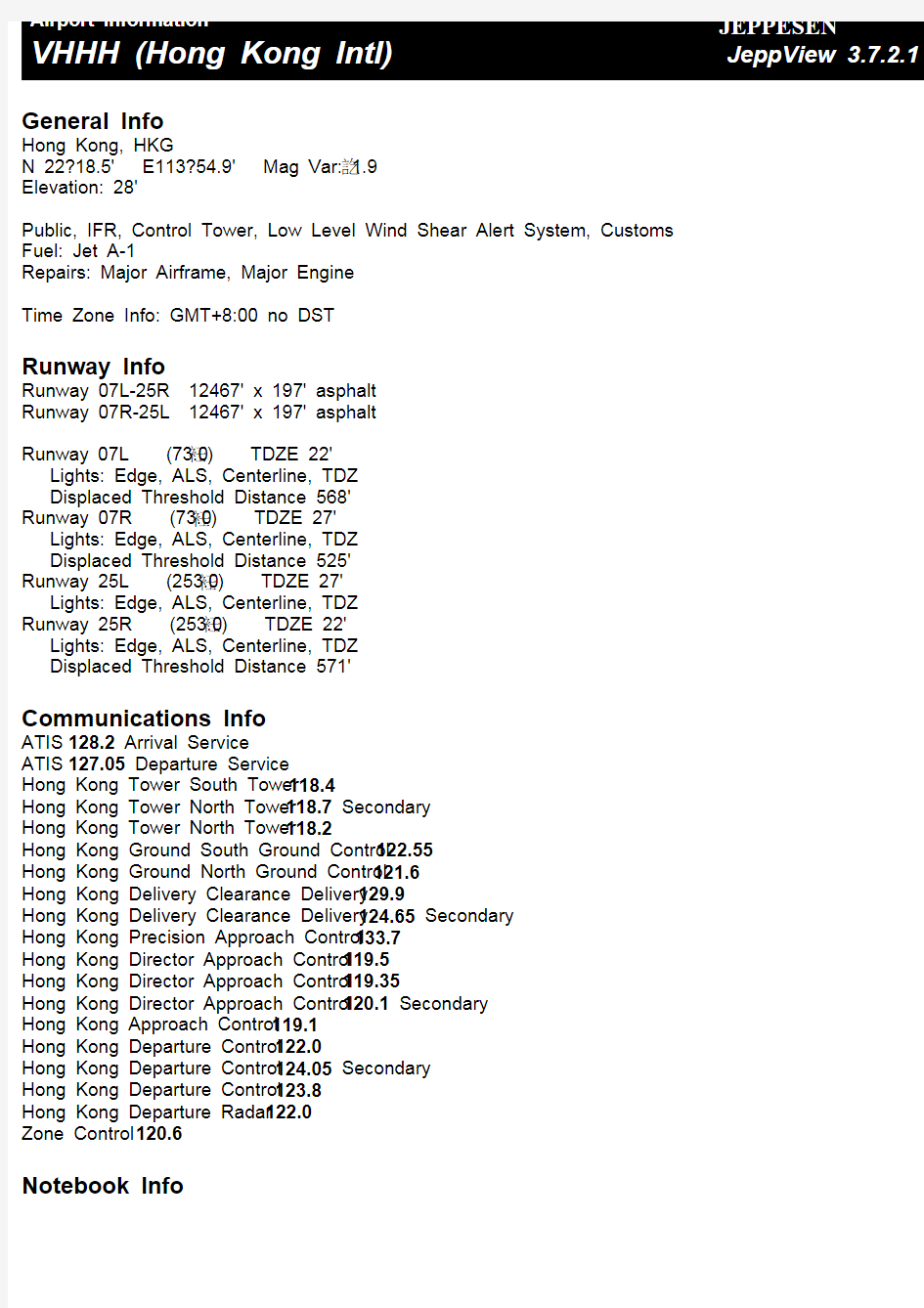
General Info Hong Kong, HKG N 22?18.5' E113?54.9' Mag Var: 1.9訖 Elevation: 28' Public, IFR, Control Tower, Low Level Wind Shear Alert System, Customs Fuel: Jet A-1 Repairs: Major Airframe, Major Engine Time Zone Info: GMT+8:00 no DST Runway Info Runway 07L-25R 12467' x 197' asphalt Runway 07R-25L 12467' x 197' asphalt Runway 07L (73.0衽) TDZE 22' Lights: Edge, ALS, Centerline, TDZ Displaced Threshold Distance 568' Runway 07R (73.0衽) TDZE 27' Lights: Edge, ALS, Centerline, TDZ Displaced Threshold Distance 525' Runway 25L (253.0衽) TDZE 27' Lights: Edge, ALS, Centerline, TDZ Runway 25R (253.0衽) TDZE 22' Lights: Edge, ALS, Centerline, TDZ Displaced Threshold Distance 571' Communications Info ATIS 128.2 Arrival Service ATIS 127.05 Departure Service Hong Kong Tower South Tower 118.4 Hong Kong Tower North Tower 118.7 Secondary Hong Kong Tower North Tower 118.2 Hong Kong Ground South Ground Control 122.55 Hong Kong Ground North Ground Control 121.6 Hong Kong Delivery Clearance Delivery 129.9 Hong Kong Delivery Clearance Delivery 124.65 Secondary Hong Kong Precision Approach Control 133.7 Hong Kong Director Approach Control 119.5 Hong Kong Director Approach Control 119.35 Hong Kong Director Approach Control 120.1 Secondary Hong Kong Approach Control 119.1 Hong Kong Departure Control 122.0 Hong Kong Departure Control 124.05 Secondary Hong Kong Departure Control 123.8 Hong Kong Departure Radar 122.0 Zone Control 120.6 Notebook Info
第一章航图概述 图幅尺寸:最佳尺寸210*148mm,即国际标准组织规定的A5尺寸 负载量:指图面上各种划线、符号和注记所占面积的比例。 颜色:航图尽量减少所用色彩的数量或直接使用单色制作与印刷。如用彩色,一般只采用黑、灰和蓝色 航图的定位方法:航图中的所有地物和符号都采用真北定位,而所需要注明方向的数据,都以磁北进行注记,同时,在图上注明磁差,并加注年变率。 航图的分类:国际民航组织在附件四《航图》中规定了17种航图的制图规范和要求。 必须提供的航图(六种) 机场障碍物图—ICAO、A型(运航限制),机场图—ICAO,世界航图—ICAO 1:1000000 精密进近地形图—ICAO ,仪表进近图—ICAO,航路图—ICAO 非强制性制作的航图 机场障碍物图—ICAO、B型,机场地面运行图—ICAO,航空器停放/停靠图—ICAO 航空地图—ICAO 1:500 000 ,航空领航图—ICAO,小比例尺,作业图—ICAO 机场图 从航空器停机位到跑道;从跑道到航空器停机位;在该机场运行的基本资料 停机位置图 侯机楼设施复杂的机场提供停机位置图,便于航空器在滑行道和停机位之间以及航空器的停放/停靠等地面活动。图中包含停机位置、停机位编号、滑行路线和通信频率的资料。 标准仪表进场图STAR 已经设立标准仪表进场航线,但在区域图中不能详细表示的机场,提供标准仪表进场图。本图提供航路飞行阶段到进近阶段按指定的标准仪表进场航线飞行所需的资料 . 仪表进近图 已制定仪表进近程序的机场提供仪表进近图。通常每一种进近程序都有单独的仪表进近图 应的等待程序(适用时)。图中包含机场、禁区、限制区、危险区、无线电通信设施、导航设施、最低扇区高度、以平面图和剖面图表示的程序的飞行航迹、机场运行标准、地形障碍物等资料和补充资料。 标准仪表离场图SID 已经设立标准仪表离场航线,但在区域图中不能详细表示的机场,提供标准仪表离场图。本图提供起飞阶段到航路飞行阶段按指定的标准仪表离场航线飞行所需的资料。 机场障碍物图—A型(运行限制) 提供机场起飞航径区内障碍物的详细资料,并以平面图和剖面图的形式表示。这些障碍物资料向航空器经营人提供遵守运行限制所必要的数据。 精密进近地形图 提供在最后进近阶段的划定区域内详细的地形资料,包括平面和剖面资料。航空器运营部门可以根据本图评估地形对利用无线电高度表确定决断高所产生的影响。所有II、III 类精密进近跑道均提供精密进近地形图 航路图 航路图向机组提供根据空中交通服务程序沿空中交通服务航路飞行需要的有关资料。本图的覆盖范围为中国飞行情报区。图中数据包含所有供民航使用的机场、禁区、限制区、危险区以及详细的空中交通服务系统等资料和补充资料。
2008年南航大“4+1签派培训”Jeppesen 航图复习提纲1、使用杰普逊航图必须记住以下使用惯例: 速度的单位是节; 时间是世界协调时(UTC);垂直距离的单位是英尺;水平距离的单位是海里;航向是磁航向,除非后缀T表示为真航向; 航图投影是兰勃特圆锥投影。 2、航图航行通告 航图变更通知每周或隔周发布一次。该部分包括国家空域系统中相关的临时航行通告(时限长于每日航行通告)和设施关闭、频率改变和临时不可用的助航设备的通告。航图变更通知按国家、城市和机场的字母顺序公布。 4、航图索引号 终端区航图总体上可以分为区域图、离场图、进场图、机场图等“0”系列图和进近图两类。 1)、“0”系列航图索引号 “0”系列航图的索引号格式为“?0 - #×”。“?”号为从1开始的数字,代表同一个城市的机场编号,“#”号代表除了进近图以外的终端区航图类型,为数字;当机场只有一张某一类型的终端区航图时,“×”号为空,当机场有多张某一类型的终端区航图时,从第二张航图开始,“×”号为从A开始顺序编号的大写字母。 “0”系列航图索引号代表的航图类型 2)、进近图索引号 进近图索引号一般用3位数字表示,第一位数字为同一城市的不同机场编号,第二位数字代表进近程序类型,第三位数字代表同一类进近程序的不同顺序号,按照跑道编号从低到高依次编排,若同类进近图还有次级的划分类型,其编号就在第三位数字后面从A开始依次编号。
进近图索引号 5、航路图覆盖代码、全称 杰普逊航路图覆盖范围代码、全称一览表 代码 全称 E(HI) 欧洲EUROPE 高空航路图 E(LO) 欧洲EUROPE 低空航路图 E(H/L) 欧洲EUROPE 高/低空航路图 US(HI) 美国UNITED STATES 高空航路图 US(LO) 美国UNITED STATES 低高空航路图 US(LO)NE 美国东北沿海NORTHEAST COASTAL 低空航路图 US(LO)SE 美国东南沿海SOUTHEAST COASTAL 低空航路图 CA(HI) 加拿大-阿拉斯加CANADA-ALASKA 高空航路图 CA(LO) 加拿大-阿拉斯加CANADA-ALASKA 低空航路图 CA(H/L) 加拿大-阿拉斯加CANADA-ALASKA 高/低空航路图 AK(LO) 阿拉斯加ALASKA 低空航路图 AT(H/L) 大西洋ATLANTIC OCEAN 高/低空航路图 P(H/L) 太平洋PACIFIC OCEAN 高/低空航路图 LA(H/L) 拉丁美洲LATIN AMERICA 高/低空航路图 AU(LO) 澳大利亚AUSTRALIA 低空航路图 AU(HI) 澳大利亚AUSTRALIA 高空航路图 AS(H/L) 澳大利亚AUSTRALIA 高/低空航路图 A(HI) 非洲AFRICA 高空航路图 A(H/L) 非洲AFRICA 高/低空航路图 FE(H/L) 远东FAR EAST 高/低空航路图 SA(HI) 南美SOUTH AMERICA 高空航路图 第一位: 同一城市机场编号 第二位:进近程序类型 1-ILS, MLS, GLS or LOC 2-RNAV (GPS ) 3-VOR 6-NDB 8-GPS 9-RNAV, Visual, Vicinity 第三位: 同一类型的顺序号
CONTENTS 绪论 机场&停机位置图02 SID图 03 航路&区域图 04 STAR图 05 06IAC图
定义 航图是指以满足民用航空运行及其他航空 活动的需要为目的,表示各种航空要素及 必要的自然地理和人文要素的专用地图。 航图是以表现机场、导航台、航线及各种 助航设施等一些航行要素的空间分布为主 要内容的图,全称为航空地图 (Aeronatical Chart )。1航图的分类 机场障碍物图(A&B ) 区域图IAC 图精密进近地形图 SID 图目视进近图航路图STAR 图机场&停机位图... ...3一般制图规范1.图幅尺寸2.负载量3.颜色4.资料的现势性2. 航图的定位方法6.地形标绘7.航图的衔接 21. 绪论
2.机场&停机位置图 机场图主要包括 1.标题 2.平面图 3.起飞最低标准 4.主要灯光 5.备注和图边注记
主要灯光备注和图边注记
图的名称机场 基准 点坐 标 机场 标高通信资料城市/机场名称 1)机场基准点坐标(Airport Reference Point,ARP) 2)机场标高起飞着陆区最高点的标高。通常以主跑道中线上最高点的标高作为该机场的标高,一般精确到0.1m,标高数据应该 由机场当局提供,帮助飞行员在使用修正海压(QNH)作 为高度表基准完成起飞离场及进场、进近着陆过程中,了 解航空器在空中时距离机场道面的垂直高度,因此需要在 资料中给出机场标高的数据。
3)通信资料在机场图上,通信资料包括航空器在机场运行所需的自动化设备和管制单位的通信信息,括号中的频率为备用频率。通信频率是航空器在 机场道面上运行时会用到的频率。 自动终端情报服务(Automatic Terminal Information Service,ATIS)、 放行席(Delivery)、地面席(Ground,GND)、塔台席 (Aerodrome Control Tower,TWR)、机坪席(Apron,APN)。 目前我国空管使用的通信频率占用的频段为118.0~135.975MHz,频 率指配间隔为0.025MHz,一般情况下塔台使用118.0~118.875MHz和 124.3~124.375MHz,ATIS使用126.2~128.875MHz范围中小数点后 第一位数字为偶数的频率。
General Info Tianjin, CHN N 39?07.4' E117?20.7' Mag Var: 5.8癢 Elevation: 13' Public, IFR, Control Tower, Customs, Landing Fee Fuel: Jet A-1 Repairs: Minor Airframe, Minor Engine Time Zone Info: GMT+8:00 no DST Runway Info Runway 16L-34R 10499' x 148' concrete Runway 16R-34L 11811' x 164' asphalt Runway 16L (160.0癕) TDZE 12' Lights: Edge, ALS, Centerline, TDZ Runway 16R (160.0癕) TDZE 8' Lights: Edge, ALS, Centerline Displaced Threshold Distance 1312' Stopway Distance 197' Runway 34L (340.0癕) TDZE 8' Lights: Edge, ALS, Centerline Right Traffic Stopway Distance 197' Runway 34R (340.0癕) TDZE 12' Lights: Edge, ALS, Centerline, TDZ Right Traffic Communications Info ATIS 126.4 Tianjin Tower 130.0 Secondary Tianjin Tower 127.9 Tianjin Tower 118.2 MF Ramp Control Ground Control 121.95 Tianjin Approach Control 127.9 At or below 11800' Tianjin Approach Control 125.25 Tianjin Approach Control 120.9 At or below 11800' Secondary Notebook Info