Settlements induced by tunneling in Soft Ground
- 格式:pdf
- 大小:1.61 MB
- 文档页数:31
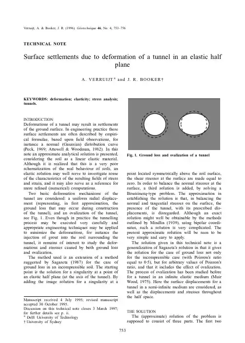
Effects of twin tunnels construction beneath existing shield-driven twintunnelsQian Fang a ,⇑,Dingli Zhang a ,QianQian Li a ,Louis Ngai Yuen Wong ba School of Civil Engineering,Beijing Jiaotong University,Beijing 100044,ChinabSchool of Civil and Environmental Engineering,Nanyang Technological University,Singapore 639798,Singaporea r t i c l e i n f o Article history:Received 16December 2013Received in revised form 14August 2014Accepted 7October 2014Available online 28October 2014Keywords:Tunnelling Settlement Ground lossSoil/structure interactiona b s t r a c tThis paper presents a case of closely spaced twin tunnels excavated beneath other closely spaced existing twin tunnels in Beijing,China.The existing twin tunnels were previously built by the shield method while the new twin tunnels were excavated by the shallow tunnelling method.The settlements of the existing tunnels and the ground surfaces associated with the new tunnels construction were systematically mon-itored.A superposition method is adopted to describe the settlement profiles of both the existing tunnels and the ground surfaces under the influence of the new twin tunnels construction below.A satisfactory match between the proposed fitting curves and the measured settlement data of both the existing tun-nels and the ground surfaces is obtained.As shown in a particular monitoring cross-section,the settle-ment profile shapes for the existing tunnel and the ground surface are different.The settlement profile of the existing structure displays a ‘‘W’’shape while the ground surface settlement profile displays a ‘‘U’’shape.It is also found that due to the flexibility of the segmental lining,the ground losses obtained from the existing tunnel level and the ground surface level in the same monitoring cross-section are nearly the same.Ó2014Elsevier Ltd.All rights reserved.1.IntroductionUrban underground areas are congested with infrastructures ranging from small pipelines and cables to large tunnels and foun-dations of high-rise buildings.With the increasing number of sub-ways constructed in urban areas,cases of tunnelling adjacent to existing structures are common.Due to the inherent complexities of the existing structure–ground–tunnel interactions,it is very challenging to ensure both the serviceability of existing structures and the safety of new tunnels construction.A significant amount of research has been performed to study the ground movements induced by the construction of twin tun-nels or more (e.g.,Addenbrooke and Potts,2001;Chapman et al.,2003;Hunt,2005;Ahn et al.,2006;Chapman et al.,2007;Laver,2011;Divall et al.,2012;Garner and Coffman,2013;Divall,2013;Do et al.,2014;Ocak,2014).The additional movements caused by the interaction between tunnels may result in asymmet-ric settlement troughs.The behaviours of existing structures induced by adjacent tunnelling have also been extensively studied,most of which focus on the influences on existing buildings (e.g.,Boscardin and Cording,1989;Burland,1995;Boone,1996;Burd et al.,2000;Mroueh and Shahrour,2003;Zhang et al.,2013)or pipelines (e.g.,Klar et al.,2005;Vorster et al.,2005;Fang et al.,2011;Zhang et al.,2012).Relatively speaking,there are only lim-ited published data related to the response of existing tunnels to new tunnels construction nearby.Cooper et al.(2002)presented extensive monitoring records taken from the interior of two exist-ing 3.8m internal diameter tunnels during the construction of three 9.1m external diameter running tunnels below in London clay (on the Heathrow Express).The vertical clearance between the new and existing tunnels is 7m and there is a skew of 69°between them.Both the new and existing tunnels were con-structed by using the shield method.Mohamad et al.(2010)adopted a distributed strain sensing technique to examine the per-formance of an approximate 8.5m diameter old masonry tunnel during the construction of a 6.5m external diameter tunnel beneath it.The minimum vertical clearance between the new and existing tunnels is about 3.6m.The new and the existing tun-nels were constructed using the shield method and the cut and cover method respectively.Li and Yuan (2012)presented data for the construction of two 6m external diameter shield-driven tun-nels below an existing 13.6m high double-deck tunnel.The verti-cal clearances from the right tunnel and the left tunnel to the existing tunnel are about 2.76m and 1.78m respectively.Ng et al.(2013)investigated the response of an existing tunnel to/10.1016/j.tust.2014.10.0010886-7798/Ó2014Elsevier Ltd.All rights reserved.⇑Corresponding author.Tel.:+861051688115;fax:+861051688111.E-mail address:qfang@ (Q.Fang).the excavation of a new tunnel perpendicularly below it by using three-dimensional centrifuge tests and numerical modelling.According to the literature,there is very limited knowledge on the response of an existing shield-driven tunnel to later tunnel-ling-induced disturbances.The data related to the relationship between the existing tunnel settlement and ground surface settle-ment are even less.In this paper,a case of two closely spaced tun-nels excavated beneath two other existing closely spaced tunnels in Beijing,China is presented.The response of existing tunnels to new tunnels construction is investigated based on the monitoring data.The deformation characteristics of the existing tunnels and the ground surfaces in two monitoring cross-sections are com-pared respectively.2.Project overviewA plan view and cross-sectional view of the existing and the new tunnels at the Ping’anli station in Beijing are shown in Figs.1and 2respectively.The existing circular shaped twin tunnels,run-ning north–south,are parts of the Beijing subway Line 4.They are horizontally parallel and are referred to as the ‘‘west tunnel’’and the ‘‘east tunnel’’.The clearance between them is 9.0m.They were driven by the earth pressure balance shield.The external and the internal radius of the precast segmental lining are 3.0m and 2.7m respectively.The segmental lining consists of five segments with a key segment (Fig.3).The length of each segment is 1.2m.The segments are rotated from ring to ring so that the joints do not line up along the longitudinal axis of the tunnel.The overbur-den depth of the existing tunnels is about 12.4m.The new horseshoe shaped twin tunnels,running east–west,are parts of the Beijing subway Line 6.The clearance between them is approximately 9.5m,which slightly decreases from west to east.The new twin tunnels are referred to as the ‘‘north tunnel’’and the ‘‘south tunnel’’,respectively.They were excavated by using the shallow tunnelling method.The shallow tunnelling method relying on manpower-excavation is particularly designed for shal-lowly-buried tunnels constructed in a densely built urban area (Fang et al.,2012).The thicknesses of the primary lining and sec-ondary lining are 250mm and 300mm respectively.A waterproof-ing system is sandwiched between the primary and the secondarylinings.The new twin tunnels were excavated perpendicularly beneath the existing twin tunnels.The vertical clearance between the new and existing tunnels is only 2.6m.The top heading (with support core and temporary invert)-bench-invert excavation approach was adopted for the new twin tunnels excavation (Fig.4).A typical geological profile of the project is shown in Fig.5.The profile reveals that the existing tunnels are located mainly in gravel,while the new tunnels are located in interbedded silty clay,silt,fine sand and gravel.Some mean values of the physical and mechanical parameters of the soils retrieved from the site investi-gation report are shown in Table 1.According to the project design,a rectangular vertical shaft was first excavated.Then a horseshoe shaped cross adit with flat walls and invert was excavated horizontally from the shaft sheeting.After that,the new twin tunnels were excavated perpendicularly from the adit wall.The north tunnel was first excavated followed by the south tunnel with a certain lag.In order to safeguard the existing twin tunnels and facilitate the new twin tunnels construc-tion,grouting into and above the new twin tunnels was performed.A total of eight grout holes,each of which about 30m long,were drilled horizontally from the cross adit wall.The grouting was achieved through a sleeve pipe known as a tube àmanchette (TAM).A grout mixture composed of ordinary Portland cement and sodium silicate was selected.The cross section and the longi-tudinal section of the long-span pre-grouting are shown in Fig.6.During the new twin tunnels construction,forepolings and footing reinforcement piles were adopted as the auxiliary measures (Fig.4).3.Monitoringyout of monitoring pointsDuring the new twin tunnels construction,the deformation of the existing tunnels and the ground surfaces were monitored.The layout of the monitoring points along the existing west tunnel and the east tunnel is shown in Fig.7.The parenthesised texts in Fig.7indicate those for the east tunnel section.The first letter ‘‘W’’or ‘‘E’’of the monitoring point label indicates the ‘‘west tun-nel’’or the ‘‘east tunnel’’.The second letter ‘‘e’’or ‘‘s’’indicatesQ.Fang et al./Tunnelling and Underground Space Technology 45(2015)128–137129the ‘‘existing tunnel’’or the ‘‘surface’’.The ground surface settle-ment monitoring points were installed from the road surface into the backfill ground to represent the ‘‘real’’ground surface settle-ment,which were monitored with total station.The settlement monitoring points of the existing twin tunnels were set up along the invert of each line,and monitored by a hydrostatic level system (Li et al.,2013).At each point of the existing tunnels to be moni-tored,hydrostatic level cells were fastened.The signals observed were sent back to the central monitoring system and recorded at 30min intervals.It is worth noting that the monitored deformation nearby the portal can also be affected by the shaft and cross adit excavation.In order to study the deformation induced bythe130Q.Fang et al./Tunnelling and Underground Space Technology 45(2015)128–137new twin tunnels construction alone,the deformation readings were taken only after the long-span pre-grouting had been performed.3.2.Monitoring dataThe development of the settlements for some typical points of the existing west and east tunnels is shown in Fig.8.The development of the ground surface settlements for some typical points above the existing west and east tunnels is shown in Fig.9.The north tunnel construction was performed under the existing west tunnel on August 8th and under the east tunnel on September 11th.In this part of the project,the south tunnel face was about 5m behind the north tunnel face and the distance between the top heading and the bench of each tunnel varied from 3m to 6m.Due to the short distance between the twintunnels,Q.Fang et al./Tunnelling and Underground Space Technology 45(2015)128–137131the settlements associated with a single tunnel construction can-not be obtained directly from the monitoring data.It is noted that the hydrostatic level system was very sensitive to the ambient interferences,such as the passage of a train nearby a monitoring point.As such,representative data relatively free of interferences, which were obtained during the non-service time of Line4after midnight,are selected from the huge volume of automatically recorded data to represent the daily settlement magnitudes of the existing tunnels due to the construction of the new twin tunnels.4.Analysis of monitoring data4.1.Superposition methodAccording to the monitoring data,we can construct the trans-verse settlement profiles of both the existing tunnels and the ground surfaces.The magnitude and shape of a settlement profile are influenced by tunnelling method,ground conditions,as well as tunnel dimensions and buried depth,etc.It is widely reported that the settlement profile for a single tunnel takes the shape ofTable1Physical and mechanical properties of soils.ID Group Bulk density(kg/m3)Water content(%)Standard(dynamic)penetration test N63.5Cohesion(kPa)Friction angle(°) t Silt197020.85129.429.3 t1Silty clay198024.581823.816.0 u Fine sand200010.6347032.0 u1Medium sand2030–53038.0 v Gravel2120–78(dynamic)045.0 w Silty clay198025.151230.917.9 w2Silt198020.921616.727.3 x1Fine sand203010.9058032.0 x Gravel2150–101(dynamic)045.0132Q.Fang et al./Tunnelling and Underground Space Technology45(2015)128–137an inverted Gaussian distribution curve symmetrical to the tunnel axis at right ing a Gaussian distribution curve to describe ground settlement profile wasfirst proposed by Peck(1969)and later verified byfield and laboratory tests(Mair et al.,1993).The shape of the settlement trough can be described by using the fol-lowing equation:S¼S max expÀx2 2i2¼AViffiffiffiffiffiffiffi2pp expÀx22i2ð1Þwhere x is the distance from the central line of a tunnel,i(or trough width)is the distance from the tunnel centre line to the inflection of the trough,S max is the maximum settlement,A is the tunnel cross-sectional area.V is the percentage of ground loss assuming the ground is incompressible.i.e.,V=V s/A and V s is the volume loss due to tunnelling.i can be calculated by a simple method proposed by Mair et al.(1981):i¼Kðz0ÀzÞð2Þwhere z0is the depth to the new tunnel axis and z is a concerned depth,K is an empirically determined trough width parameter.For multiple tunnels,it is not always possible to represent a transverse settlement profile by a single Gaussian curve.A common practice is to superpose the independent transverse settlement profiles calcu-lated for each individual excavation to obtain thefinal accumulative settlement profile.New and O’ReilIy(1991)provided a method of calculating surface settlement for twin tunnels driven simulta-neously.The same method had been reported by GCG(1992). Hunt(2005)provided a method for predicting ground movements above twin tunnels construction based on modifying the ground movements above the second tunnel in the‘‘overlapping zone’’where the soil is assumed to have been previously disturbed by thefirst tunnel.This modified method is validated against a number of case studies(Hunt,2005)and is also proved to be applicable to the laboratory model test data(Chapman et al.,2007).However, additional parameters are required in this method.In this research, in order to describe the settlement profiles of both the existing tun-nels and the surfaces induced by the separately constructedtwin Q.Fang et al./Tunnelling and Underground Space Technology45(2015)128–137133tunnels,a superposition method is introduced to separate the accu-mulated settlement profile into settlement profiles attributed by each tunnel.Although this method is not directly applicable to cases where plastic deformation occurs,similar method has been exten-sively adopted by many researchers(e.g.,Peck,1969;Suwansawat and Einstein2007).That is:S¼S max1expÀxþL=2ðÞ22i21"#þS max2expÀxÀL=2ðÞ22i22"#¼A1V1ffiffiffiffiffiffiffi2ppi1expÀxþL=2ðÞ22i21"#þA2V2ffiffiffiffiffiffiffi2ppi2expÀxÀL=2ðÞ22i22"#ð3Þwhere the subscript numbers1and2stand for thefirst tunnel exca-vated and the second tunnel excavated,L is the horizontal distance between the centre lines of the twin tunnels.4.2.Settlement profile of existing tunnels and ground surfacesUpon reviewing the recorded settlements for this project,they were found to be influenced by the top heading,bench and invert excavation of each tunnel.However,since the lag maintained between the top heading and the bench(and invert)of each of the twin tunnels was only3–6m and the distance between the leading faces of the twin tunnels varied(the north tunnel was about5m ahead of the south tunnel),it is unjustified to separate the settlement profile into profiles due to different construction stages of each tunnel.Therefore we only use the proposed superpo-sition method to estimate thefinal settlement profiles of the exist-ing tunnels and the ground surfaces.Thefinal settlement data of the existing tunnels and the ground surfaces of the two sections, along with thefitting curves obtained by the proposed method are shown in Fig.10.Four parameters,V1,V2,K1and K2,arefitted 134Q.Fang et al./Tunnelling and Underground Space Technology45(2015)128–137simultaneously to each set of data.The values of i 1and i 2can be calculated by Eq.(2)and the values of S max1and S max2can be cal-culated by Eq.(3).A summary of the data obtained by fitting and calculation is shown in Table 2.The adjusted coefficient of deter-mination (Adj.R -Square)indicates how well the data points match the proposed fitting curve.The closer the fit,the closer the adjusted R 2will be to the value of 1.The adjusted coefficients of determina-tion shown in Table 1are all above 0.9,indicating that the data points are appropriately fitted by the proposed method.A comparison of the total settlement profiles of the existing tunnel and the ground surface at each monitored cross-section reveals that the existing tunnel settlement profile displays a dou-ble-trough ‘‘W’’shape,while the ground surface settlement profile displays a single-trough ‘‘U’’shape.This phenomenon is mainly ascribable to their different overburden depth.As the buried depth increases,the more pronounced the double-trough shape of the settlement profile will be.The double-trough deformation pattern of the existing tunnels also indicates the flexibility of the segmen-tal lining,which means the existing tunnels follow the green field deformation.Due to the flexibility of the existing tunnels,the ground above the new tunnels is able to deform continuously.Therefore the total percentages of ground loss (V 1+V 2)obtained from different levels above the new tunnels in one monitoring cross-section,such as the existing tunnel level and the ground sur-face level,are nearly the same only with a slight increase from sur-face to subsurface.According to the monitoring results shown in Fig.10,we can observe that larger settlements both at surface and subsurface are reported above the north tunnel,which was first excavated.According to the fitting results shown in Table 2,it is foundthatQ.Fang et al./Tunnelling and Underground Space Technology 45(2015)128–137135the ground losses and the trough width parameters associated with the second tunnel excavation are larger than those due to thefirst tunnel at different depths.Similar results have been reported by other researchers(e.g.,Hunt,2005;Chapman et al., 2007;Divall,2013).Referring to the two Gaussian curves simply superimposed to represent the monitored total settlements,we can observe an interesting phenomenon that larger maximum settlement of a Gaussian curve is reported above thefirst tunnel excavated(S max1) at the existing tunnel level,while larger maximum settlement of a Gaussian curve is found above the second tunnel excavated(S max2) at the surface level.A similar trend that the maximum settlement of the Gaussian curvefitted for the second tunnel is larger than that for thefirst tunnel at the surface level can also be found in the laboratory model tests performed by Chapman et al.(2007). However,the mismatching phenomenon at different depths is rarely mentioned.We believe that with the development of settle-ment from the tunnel crown to the surface,the larger volume loss associated with the second tunnel at the subsurface level may increase the magnitude of the maximum settlementfitted for the second tunnel at the surface level.Therefore the larger maximum settlementfitted for a single tunnel may be revealed above thefirst tunnel at subsurface and above the second tunnel at surface.5.ConclusionsThis paper presents a case of closely spaced twin tunnels con-structed beneath two other existing closely spaced tunnels.The measures taken in this project and related monitoring data are elaborated.The key results obtained in this study can be summa-rised as follows:(1)A superposition method is proposed to describe the settle-ment profile due to the construction of twin tunnels below.A satisfactory match between the proposedfitting curvesand the measured settlement readings is obtained.(2)The settlement profile of the existing structure displays adouble trough‘‘W’’shape while the ground surface settle-ment profile displays a single trough‘‘U’’shape.This phe-nomenon is mainly ascribed to their different overburden depth.As the depth increases,the more pronounced the double-trough shape of the settlement profile will be for a twin tunnels project.(3)The ground losses obtained from the existing tunnel leveland the ground surface level in the same monitoring cross-section were nearly the same.It implies that the segmental lining has a sufficientflexibility to deform in a manner that matched the deformation of the surrounding ground. AcknowledgmentsThe authors gratefully acknowledge thefinancial support by the Science and Technology Project of Ministry of Transport of the People’s Republic of China under Grant2013318Q03030and the National Natural Science Foundation of China under Grant 51108020.ReferencesAddenbrooke,T.I.,Potts, D.M.,2001.Twin tunnel interaction–surface and subsurface effects.Int.J.Geomech.1(2),249–271.Ahn,S.K.,Chapman, D.N.,Chan, A.H.,Hunt, D.V.L.,2006.Model Tests for Investigating Ground Movements cause by Multiple Tunnelling in Soft Ground.Taylor and Francis,pp.1133–1137.Boone,S.J.,1996.Ground-movement-related building damage.J.Geotech.Geoenviron.Eng.122(11),886–896.Boscardin,M.D.,Cording, E.J.,1989.Building response to excavation-induced settlement.J.Geotech.Eng.115(1),1–21.Burd,H.J.,Houlsby,G.T.,Augarde,C.E.,Lui,G.,2000.Modeling tunnelling-induced settlement of masonry buildings.ICE Proc.:Geotech.Eng.143,17–29. Burland,J.B.,1995.Assessment of risk of damage to buildings due to tunnelling and excavation.In:Proc.1st Int.Conf.on Earthquake Geotechnical Engineering,IS, Tokyo,pp.155–162.Chapman,D.N.,Rogers,C.D.F.,Hunt,D.V.L.,2003.Investigating the settlement above closely spaced multiple tunnel constructions in soft ground.In:Proc.of World Tunnel Congress2003,vol.2,Amsterdam,pp.629–635.Chapman,N.D.,Ahn,S.K.,Hunt, D.V.L.,2007.Investigating ground movements caused by the construction of multiple tunnels in soft ground using laboratory model tests.Can.Geotech.J.44(6),631–643.Cooper,M.L.,Chapman,D.N.,Rogers,C.D.F.,Chan,A.H.C.,2002.Movements in the piccadilly line tunnels due to the heathrow express construction.Géotechnique 52(4),243–257.Divall,S.,2013.Ground Movements associated with Twin-Tunnel Construction in Clay.PhD Thesis,City University London,UK.Divall,S.,Goodey,R.J.,Taylor,R.N.,2012.Ground movements generated by sequential twin-tunnelling in over-consolidated clay.In:2nd European Conference on Physical Modelling in Geotechnics,Delft,The Netherlands. Do,N.A.,Dias,D.,Oreste,P.,Djeran-Maigre,I.,2014.Three-dimensional numerical simulation of a mechanized twin tunnels in soft ground.Tunn.Undergr.Space Technol.42,40–51.Fang,Q.,Zhang,D.L.,Wong,L.N.Y.,2011.Environmental risk management for a cross interchange subway station construction in China.Tunn.Undergr.Space Technol.26(6),750–763.Fang,Q.,Zhang,D.L.,Wong,L.N.Y.,2012.Shallow tunnelling method(STM)for subway station construction in soft ground.Tunn.Undergr.Space Technol.29, 10–30.Garner,C.D.,Coffman,R.A.,2013.Subway tunnel design using a ground surface settlement profile to characterize an acceptable configuration.Tunn.Undergr.Space Technol.35,219–226.(GCG)Crossrail Project,1992.Prediction of Ground Movements and Associated Buildings Damage due to Bored Tunnelling.Geotechnical Consulting Group, London.Hunt, D.V.L.,2005.Predicting the Ground Movements above Twin Tunnels constructed in London Clay.PhD Thesis,University of Birmingham,UK.Klar, A.,Vorster,T.E.B.,Soga,K.,Mair,R.J.,2005.Soil–pipe interaction due to tunnelling:comparison between Winkler and elastic continuum solutions.Géotechnique55(6),461–466.Laver,R.G.,2011.Long-term Behaviour of Twin Tunnels in London Clay.PhD Thesis, University of Cambridge,UK.Li,X.G.,Yuan,D.J.,2012.Response of a double-decked metro tunnel to shield driving of twin closely under-crossing tunnels.Tunn.Undergr.Space Technol.28,18–30.Li,X.G.,Zhang,C.P.,Yuan,D.J.,2013.An in-tunnel jacking above tunnel protection methodology for excavating a tunnel under a tunnel in service.Tunn.Undergr.Space Technol.34,22–37.Mair,R.J.,Gunn,M.J.,O’Reilly,M.P.,1981.Ground movements around shallow tunnels in soft clay.In:Proceedings of the Tenth ICSMFE,Stockholm,pp.323–328.Mair,R.J.,Taylor,R.N.,Bracegirdle,A.,1993.Subsurface settlement profiles above tunnels in clays.Géotechnique43(2),315–320.Mohamad,H.,Bennett,P.J.,Soga,K.,Mair,R.J.,Bowers,K.,2010.Behaviour of an old masonry tunnel due to tunnelling-induced ground settlement.Géotechnique60(12),927–938.Table2Settlement parameters of the existing tunnels and ground surfaces.Monitoring points Monitored maximumsettlement(mm)Fitted maximumsettlement(mm)Percentage of groundloss(%)Trough widthparameterTrough width(m)Adjusted coefficientof determination(Adj.R-Square)S max1S max2V1V2K1K2i1i2West tunnel7.00 6.19 5.920.240.320.87 1.22 5.127.140.92 East tunnel 6.60 6.01 5.550.220.290.83 1.18 4.84 6.900.91 Surface above west tunnel 5.17 3.38 3.720.210.310.340.458.2111.000.98 Surface above east tunnel 4.95 3.22 3.630.200.280.340.428.2010.190.91 136Q.Fang et al./Tunnelling and Underground Space Technology45(2015)128–137Mroueh,H.,Shahrour,I.,2003.A full3-Dfinite element analysis of tunnelling-adjacent structures put.Geotech.30(3),245–253.New,B.M.,O’ReilIy,M.P.,1991.Tunnelling induced ground movements:predicting their magnitude and effects(invited review paper).In:Proc.4th Int.Conf.on Ground Movements and Structures.Pentech Press,Cardiff,pp.671–697.Ng, C.W.W.,Boonyarak,T.,Mašín, D.,2013.Three-dimensional centrifuge and numerical modeling of the interaction between perpendicularly crossing tunnels.Can.Geotech.J.50(9),935–946.Ocak,I.,2014.A new approach for estimating the transverse surface settlement curve for twin tunnels in shallow and soft soils.Environ.Earth Sci.,1–11. Peck,R.B.,1969.Deep excavation and tunneling in soft ground.state of the art report.In:7th International Conference on Soil Mechanics and Foundation Engineering,Mexico City,pp.225–290.Suwansawat,S.,Einstein,H.H.,2007.Describing settlement troughs over twin tunnels using a superposition technique.J.Geotech.Geoenviron.Eng.133(4), 445–468.Vorster,T.,Klar,A.,Soga,K.,Mair,R.,2005.Estimating the effects of tunneling on existing pipelines.J.Geotech.Geoenviron.Eng.131(11),1399–1410. Zhang,C.,Yu,J.,Huang,M.,2012.Effects of tunnelling on existing pipelines in layered put.Geotech.43,12–25.Zhang,D.L.,Fang,Q.,Hou,Y.J.,Li,P.F.,Wong,L.N.Y.,2013.Protection of buildings against damages as a result of adjacent large-span tunneling in shallowly buried soft ground.J.Geotech.Geoenviron.Eng.139(6),903–913.Q.Fang et al./Tunnelling and Underground Space Technology45(2015)128–137137。
中文5351字出处:Environmental Earth Sciences, 2011, 62(2): 357-365外文原文Surface settlement predictions for Istanbul Metrotunnels excavated by EPB-TBMS. G. Ercelebi • H. Copur • I. OcakAbstract In this study, short-term surface settlements are predicted for twin tunnels, which are to be excavated in the chainage of 0 ? 850 to 0 ? 900 m between the Esenler and Kirazlı stations of the Istanbul Metro line, which is 4 km in length. The total length of the excavation line is 21.2 km between Esenler and Basaksehir. Tunnels are excavated by employing two earth pressure balance (EPB) tunnel boring machines (TBMs) that have twin tubes of 6.5 m diameter and with 14 m distance from center to center. The TBM in the right tube follows about 100 m behind the other tube. Segmental lining of 1.4 m length is currently employed as the final support. Settlement predictions are performed with finite element method by using Plaxis finite element program. Excavation, ground support and face support steps in FEM analyses are simulated as applied in the field. Predictions are performed for a typicalgeological zone, which is considered as critical in terms of surface settlement. Geology in the study area is composed of fill, very stiff clay, dense sand, very dense sand and hard clay, respectively, starting from the surface. In addition to finite element modeling, the surface settlements are also predicted by using semi-theoretical (semi-empirical) and analytical methods. The results indicate that the FE model predicts well the short-term surface settlements for a given volume loss value. The results of semi-theoretical and analytical methods are found to be in good agreement with the FE model. The results of predictions are compared and verified by field measurements. It is suggested that grouting of the excavation void should be performed as fast as possible after excavation of a section as a precaution against surface settlements during excavation. Face pressure of the TBMs should be closely monitored and adjusted for different zones.Keywords Surface settlement prediction _ Finite element method _ Analytical method _ Semi-theoretical method _ EPB-TBM tunneling _Istanbul MetroIntroductionIncreasing demand on infrastructures increases attention to shallow soft ground tunneling methods in urbanized areas. Many surface and sub-surface structures make underground construction works very delicate due to the influence of grounddeformation, which should be definitely limited/controlled to acceptable levels. Independent of theexcavation method, the short- and long-term surface and sub-surface ground deformations should be predicted and remedial precautions against any damage to existing structures planned prior to construction. Tunneling cost substantially increases due to damages to structures resulting from surface settlements, which are above tolerable limits (Bilgin et al. 2009).Basic parameters affecting the ground deformations are ground conditions, technical/environmental parameters and tunneling or construction methods (O’Reilly an d New 1982; Arioglu 1992; Karakus and Fowell 2003; Tan and Ranjit 2003; Minguez et al. 2005; Ellis 2005; Suwansawat and Einstein 2006). A thorough study of the ground by site investigations should be performed to find out the physical and mechanical properties of the ground and existence ofunderground water, as well as deformation characteristics, especially the stiffness. Technical parameters include tunnel depth and geometry, tunnel diameter–line–grade, single or double track lines and neighboring structures. The construction method, which should lead to a safe and economic project, is selected based on site characteristics and technical project constraints and should be planned so that the ground movements are limited to an acceptablelevel. Excavation method, face support pressure, advance (excavation) rate, stiffness of support system, excavation sequence and ground treatment/improvement have dramatic effects on the ground deformations occurring due to tunneling operations. The primary reason for ground movements above the tunnel, also known as surface settlements, is convergence of the ground into the tunnel after excavation, which changes the in situ stress state of the ground and results in stress relief. Convergence of the ground is also known as ground loss or volume loss. The volume of the settlement on the surface is usually assumed to be equal to the ground (volume) loss inside the tunnel (O’Reilly and New 1982).Ground loss can be classified as radial loss around the tunnel periphery and axial (face) loss at the excavation face (Attewell et al. 1986; Schmidt 1974). The exact ratio of radial and axial volume losses is not fully demonstrated or generalized in any study. However, it is possible to diminish or minimize the face loss in full-face mechanized excavations by applying a face pressure as a slurry of bentonite–water mixture or foam-processed muck. The ground loss is usually more in granular soils than in cohesive soils for similar construction conditions. The width of the settlement trough on both sides of the tunnel axis is wider in the case of cohesive soils, which means lower maximum settlement for the same amount of ground loss.Time dependency of ground behavior and existence of underground water distinguish short- and long-term settlements (Attewell et al. 1986). Short-term settlements occur during or after a few days (mostly a few weeks) of excavation, assuming that undrained soil conditions are dominant. Long-term settlements are mostly due to creep, stress redistribution and consolidation of soil after drainageof the underground water and elimination of pore water pressure inside the soil, and it may take a few months to a few years to reach a stabilized level. In dry soilconditions, the long-term settlements may be considered as very limited.There are mainly three settlement prediction approaches for mechanized tunnel excavations: (1) numerical analysis such as finite element method, (2) analytical method and (3) semi-theoretical (semi-empirical) method. Among them, the numerical approaches are the most reliable ones. However, the results of all methods should be used carefully by an experienced field engineer in designing the stage of an excavation project.In this study, all three prediction methods are employed for a critical zone to predict the short-term maximum surface settlements above the twin tunnels of the chainage between 0 ? 850 and 0 ? 900 m between Esenler and Kirazlıstations of Istanbul Metro line, which is 4 km in length. Plaxis finite element modeling program is used fornumerical modeling; the method suggested by Loganathan and Poulos (1998) is used for the analytical solution. A few different semi-theoretical models are also used for predictions. The results are compared and validated by field measurements. Description of the project, site and construction methodThe first construction phase of Istanbul Metro line was started in 1992 and opened to public in 2000. This line is being extended gradually, as well as new lines are being constructed in other locations. One of these metro lines is the twin line between Esenler and Basaksehir, which is 21.2 km. The excavation of this section has been started in May 2006. Currently, around 1,400 m of excavationhas already been completed. The region is highly populated including several story buildings, industrial zones and heavy traffic. Alignment and stations of the metro line between Esenler and Basaksehir is presented in Fig. 1.Totally four earth pressure balance (EPB) tunnel boring machines (TBM) are used for excavation of the tunnels. The metro lines in the study area are excavated by a Herrenknecht EPB-TBM in the right tube and a Lovat EPB-TBM in the left tube. Right tube excavationfollows around 100 m behind the left tube. Some of the technical features of the machines are summarized in Table 1.Excavated material is removed by auger (screw conveyor) through the machine to a belt conveyor and than loaded to rail cars for transporting to the portal. Since the excavated ground bears water and includes stability problems, the excavation chamber is pressurized by 300 kPa and conditioned by applying water, foam, bentonite and polymers through the injection ports. Chamber pressure is continuously monitored by pressure sensors inside thechamber and auger. Installation of a segment ring with 1.4-m length (inner diameter of 5.7 m and outer diameter of 6.3 m) and 30-cm thickness is realized by a wing-type vacuum erector. The ring is configured as five segments plus a key segment. After installation of the ring, the excavation restarts and the void between the segment outer perimeter and excavated tunnel perimeter is grouted by300 kPa of pressure through the grout cannels in the trailing shield. This method of construction has beenproven to minimize the surface settlements.The study area includes the twin tunnels of the chainage between 0 + 850 and 0 + 900 m, between Esenler and Kirazlı stations. Gungoren Formation of th e Miosen age is found in the study area. Laboratory and in situ tests are applied to define the geotechnical features of theformations that the tunnels pass through. The name, thickness and some of the geotechnical properties of the layers are summarized in Table 2 (Ayson 2005). Fill layer of 2.5-m thick consists of sand, clay, gravel and some pieces of masonry. The very stiff clay layer of 4 m is grayish green in color, consisting of gravel and sand. The dense sand layer of 5 m is brown at the upper levels and greenish yellow at the lower levels, consisting of clay, silt and mica. Dense sand of 3 m is greenish yellow and consists of mica. The base layer of the tunnel is hard clay, which is dark green, consisting of shell. The underground water table starts at 4.5 m below the surface. The tunnel axis is 14.5 m below the surface, close to the contact between very dense sand and hard clay. This depth isquite uniform in the chainage between 0 + 850 and 0 + 900 m.Surface settlement prediction with finite element modelingPlaxis finite element code for soil and rock analysis is used to predict the surface settlement. First, the right tube is constructed, and then the left tube 100 m behind the right tube is excavated. This is based on the assumption that ground deformations caused by the excavation of the right tube are stabilized before the excavation of the left tube. The finite element mesh is shown in Fig. 2 using 15 stress point triangular elements. The FEM model consists of 1,838 elements and 15,121 nodes. In FE modeling, the Mohr–Coulomb failure criterion is applied.Staged construction is used in the FE model. Excavation of the soil and the construction of the tunnel lining are carried out in different phases. In the first phase, the soil in front of TBM is excavated, and a support pressure of 300 kPa is applied at the tunnel face to prevent failure at the face. In the first phase, TBM is modeled as shell elements. In the second phase, the tunnel lining is constructedusing prefabricated concrete ring segments, which are bolted together within the tunnel boring machine. During the erection of the lining, TBM remains stationary. Once a lining ring has been bolted, excavation is resumed until sufficient soil excavation is carried out for the next lining. The tunnel lining is modeled using volume elements. In the second phase, the lining is activated and TBM shell elements are deactivated.When applying finite element models, volume loss values are usually assumed prior to excavation. In this study, the FEM model is run with the assumption of 0.5, 0.75, 1 and 1.5% volume loss caused by the convergence of the ground into the tunnel after excavation. Figures 3 and 4 show total and vertical deformations after both tubes are constructed. The vertical ground settlement profile after theright tube construction is given in Fig. 5, which is in theshape of a Gaussian curve, and that after construction of both tubes is given in Fig. 6. Figure 7 shows the total deformation vectors.The maximum ground deformations under different volume loss assumptions are summarized in Table 3.Surface settlement prediction with semi-theoretical and analytical methodsSemi-theoretical predictions for short-term maximum settlement are performed using the Gaussian curve approach, which is a classical and conventional method. The settlement parameters used in semi-theoretical estimations and notations are presented in Fig. 8.The theoretical settlement (Gaussian) curve is presented as in Eq. 1 (O’Reilly and New 1982):)2(m a x 22i x e S S -= (1)where, S is the theoretical settlement (Gauss error function, normal probability curve), Smax is the maximum short-term (initial, undrained) settlement at the tunnel centerline (m), x is the transverse horizontal distance from the tunnel center line (m), and i is the point of inflexion (m). To determine the shape of a settlement curve, it is necessary to predict i and Smax values.There are several suggested methods for prediction of the point of inflexion (i). Estimation of i value in this studyis based on averages of some empirical approaches given in Eqs. 2–6:where, Z0 is the tunnel axis depth (m), 14.5 m in this study, and R is the radius of tunnel, 3.25 m in this study. Equation 3 was suggested by Glossop (O’Reilly and New 1982) for mostly cohesive grounds; Eq. 4 was suggested by O’Reilly and New (1982) for excavation of cohesive grounds by shielded machines; Eq. 5 was suggested by Schmidt (1969) for excavation of clays by shielded machines; Eq. 6 was suggested by Arioglu (1992) for excavation of all types of soils by shielded machines. As a result, the average i value is estimated to be 6.6 m in this study.There are several suggested empirical methods for the prediction of the maximum surface settlement (Smax).Schmidt suggested a model for the estimation of Smax value for a single tunnel in 1969 as given in Eq. 7 (through Arioglu 1992):where, K is the volume loss (%). Arioglu (1992), based on field data, found a good relationship between K and N (stability ratio) for face-pressurized TBM cases as in Eq. 8:where cn is the natural unit weight of the soil (kN/m3), the weighted averages for all the layers, which is 19 kN/m3 in this study; rS is the total surcharge pressure (kPa), assumed to be 20 kPa in this study; rT is TBM face pressure (kPa), which is 300 kPa in this study; and CU is the undrained cohesion of the soil (kPa), the weightedaverages for all the layers, which is 50 kPa in this study assuming that CU is equal to SU (undrained shear strength of the soil). Allaverages are estimated up to very dense sand, excluding hard clay, since the tunnel axis passes around the contact between very dense sand and hard clay. The model yields 17.1 mm of initial maximum surface settlement.Herzog suggested a model for the estimation of Smax value in 1985 as given in Eq. 9 for a single tunnel and Eq. 10 for twin tunnels (through Arioglu 1992):where, E is the elasticity modulus of formation (kPa), the weighted averages for all the layers, which is 30,000 kPa in this study, and a is the distance between the tunnel axes, which is 14 m in this study. The model yields 49.9 and 58.7 mm of initial maximum surface settlements for the right and the left tube tunnel, which is 100 mm behind the right tube, respectively.There are several analytical models for the prediction of short-term maximum surface settlements for shielded tunneling operations (Lee et al. 1992; Loganathan and Poulos 1998; Chi et al. 2001; Chou and Bobet 2002; Park 2004). The method suggested by Loganathan and Poulos (1998) is used in this study. In this method, a theoretical gapparameter (g) is defined based on physical gap in the void, face losses and workmanship value, and then the gap parameter is incorporated to a closed form solution to predict elastoplastic ground deformations. The undrained gap parameter (g) is estimated by Eq. 12:where Gp is the physical gap representing the geometric clearance between the outer skin of the shield and the liner, is the thickness of the tail shield, d is the clearance required for erection of the liner, U*3D is the equivalent 3D elastoplastic deformation at the tunnel face, and w is a value that takes into account the quality of workmanship.Maximum short-term surface settlement is predicted by theoretical Eq. 13 (Loganathan and Poulos 1998):where, t is undrained Poisson’s ratio, assumed to be of maximum 0.5; g is the gap parameter (m), which is estimated to be 0.0128 m in this study; and x is transversedistance from the tunnel centerline (m) and it is assumed to be 0 m for the maximum surface settlement. The model yields 23.0 mm of undrained maximum surface settlement.Other parameters of settlement such as maximum slope, maximum curvature and so on are not mentioned in this study.Verification of predictions by field measurements and discussionThe results of measurements performed on the surface monitoring points, by Istanbul Metropolitan Municipality, are presented in Table 4 for the left and right tubes. As seen, the average maximum surface settlements are around 9.6 mm for the right tube and 14.4 mm for the left tube, which excavates 100 m behind the right tube. Themaximum surface settlements measured around 15.2 mm for the right tube and 26.3 mm for the left tube. Higher settlements are expected in the left tube since the previous TBM excavation activities on the right tube overlaps the previous deformation. The effect of the left tube excavation on deformations of the right tube is presented in Fig. 9. As seen, after Lovat TBM in the right tube excavates nearby the surface monitoring point 25, maximum surface settlement reaches at around 9 mm; however, while Herrenknecht TBM in the left tube passes the same point, maximum surface settlement reaches at around 29 mm (Fig. 10).If the construction method applied to the site is considered, long-term (consolidation) settlements are expected to be low, since the tail void is grouted immediately after excavation. The results of predictions mentioned above and observed maximum surface settlements are summarized in Table 5.The methods suggested by Loganathan and Poulos (1998) and Schmidt (1969) connected with Arioglu’s suggestion (1992) can predict the maximum short-term surface settlements only for a single tunnel. Plaxis finite element and Herzog (1985) models can predict deformations for twin tubes.Herzog’s model (1985) yields higher maximum surface settlements than the observed ones. The reason for that is that the database of the model includes both shielded tunnels and NATM (New Austrian Tunneling Method) tunnels, of which surfacesettlements are usually higher compared to shielded tunnels. Schmidt (1969), along withArioglu’s suggestion (1992), yields predictions close to observed.Plaxis finite element modeling gives the most realistic results, provided there is correct assumption of volume loss parameter, which is usually difficult to predict. The model provides simulation of excavation, lining, grouting and face pressure in a realistic manner to predict surface and sub-surface settlements. The volume loss parameter is usually assumed to be \1% for excavation with facepressure-balanced tunnel boring machines. The realized volume loss in the site is around 1% for this study.Currently, there is difficulty yet in modeling the deformation behavior of twin tunnels. One of the most impressive studies on this issue was performed by Chapman et al. (2004). However, Chapman’s semi-theoretical method still requires enlargement of the database to improve the suggested model in his paper.ConclusionsIn this study, three surface settlement prediction methods for mechanized twin tunnel excavations be tween Esenler and Kirazlı stations of Istanbul Metro Line are applied. Tunnels of 6.5-m diameters with 14-m distance between their centers are excavated by EPM tunnel boring machines. The geologic structure of the area can be classified as soft ground.Settlement predictions are performed by using FE modeling, and semi-theoretical (semi-empirical) and analytical methods. The measured results after tunneling are compared to predicted results. These indicate that the FE model predicts well the short time surface settlements for a given volume loss value. The results of some semi-theoretical and analytical methods are found to be in goodagreement with the FE model, whereas some methods overestimate the measured settlements. The FE model predicted the maximum surface settlement as 15.89 mm (1% volume loss) for the right tube, while the measured maximum settlement was 15.20 mm. For the left tube (opened after the right), FE prediction was 24.34 mm, while measured maximum settlement was 26.30 mm.中文翻译基于盾构法的Istanbul地铁施工引起的地面沉降预测摘要在这项研究中,研究的是双线隧道的短期地面沉降,选取线路里程总长为4km的Istanbul地铁从Esenler站到Kirazl站方向850到900m区间为研究对象。
Back analysis for tunnelling induced ground movements andstress redistributionM.Karakusa,*,R.J.FowellbaDepartment of Mining Engineering,Inonu University,44280Malatya,TurkeybDepartment of Mining and Mineral Engineering,The University of Leeds,Leeds LS29JT,UKReceived 10August 2004;received in revised form 14February 2005;accepted 16February 2005Available online 3June 2005AbstractAnalysing tunnelling process in 2D plane strain conditions is widely used method to calculate tunnelling induced settlement pro-files as well as soil structure interactions.Possibility of damage to the surface and/or underground structures can be estimated using powerful finite difference method (FDM)and finite element method (FEM)of analysis.However,setting up a realistic model that would be able to achieve this goal is rather difficult.In this paper,2D FDM analysis has been conducted to assess tunnelling induced settlement,stress redistribution phenomena along with movements around shallow soft ground tunnels excavated in accordance with the New Austrian Tunnelling Method.Measurements recorded during construction of the Heathrow Express Trial Tunnel in London Clay were compared with the predicted values to validate numerical estimations.As a soil model,the Mohr–Coulomb plasticity model has been used in the FDM analysis.Results obtained from 2D FEM are also included in this paper for comparison purposes to evaluate performance of both numerical analysis procedures.Predictions from both FDM and FEM analyses proved to be procedures used within this work can be a tool in practical engineering applications to simulate tunnelling operations.Ó2005Elsevier Ltd.All rights reserved.Keywords:The Heathrow Express Trial Tunnel;FEM;FDM;London Clay;Surface and sub-surface settlement;Cable elements;Stress redistrib-ution;NATM1.IntroductionOverpopulation leading to an increase in the number of commuters in urban areas has caused acceleration in con-structing underground Metro tunnels to overcome trans-portation problems.Therefore,all the parameters having influences on the magnitude and the profiles of the surface settlement have to be investigated thoroughly as the ma-jor concern in constructing such tunnels in urban areas is to reduce and/or to control ing numerical analysis can often predict the consequences without using any full scale trial tunnels.There are empirical models developed to estimate sur-face settlements in both transverse and longitudinal directions to the tunnel axis (Peck,1969;New and O ÕR-eilly,1978;O ÕReilly,1988;Mair et al.,1993;New and Bowers,1994).These empirical models produce very good surface settlement predictions.However,consider-ing that the empirical models are mainly based on past experience,these models are conservative for a ground that has not had any tunnelling process conducted in.In the preliminary tunnel design stage,not only employing correct soil stiffness properties but also self-weight of structures on the surface to numerical models can predict the probability of damage to surface struc-tures.Therefore,there have been large numbers of numerical analyses in 2D and 3D conducted to assess tunnelling induced damage (Swoboda,1979;Gunn,0886-7798/$-see front matter Ó2005Elsevier Ltd.All rights reserved.doi:10.1016/j.tust.2005.02.007*Corresponding author.Tel.:+904223410030;fax:+904223410046.E-mail address:mkarakus@.tr (M.Karakus)./locate/tustTunnelling and Underground Space Technology 20(2005)514–524Tunnelling andUnderground Space Technologyincorporating Trenchless Technology Research1992;Shohrour and Ghorbanbeigi,1994;Swoboda et al.,1994;Dasari,1996;Swoboda et al.,1999;Mroueh and Shahrour,2003;Karakus and Fowell,2003).In the present work,2D plane strain Finite Difference analyses have been conducted to investigate ground movement profiles and stress redistribution around a NATM tunnel.Fast Lagrangian analysis of continua (FLAC)(Itasca,1993)program has been utilized to sim-ulate tunnel construction.Tunnel Excavation process has been modelled using the hypothetical modulus of elasticity(HME)soft lining approach(Powell et al., 1997).Mroueh and Shahrour(2003)has studied interac-tions of buildings with tunnels using3Dfinite element analysis.They concluded that self weight of buildings on the surface has a major role on determination of ini-tial stresses in the ground and neglecting this results in underestimation of tunnelling induced forces leading to less settlement predictions.Therefore,surcharge of 80kPa(Bowers,1997)due to existing car park over the Heathrow Trial Tunnel excavation has been in-cluded within the analysis.Surface and subsurface transverse settlement troughs, along with horizontal stress distributions measured dur-ing the Heathrow Trial Tunnel construction in1992have been compared with the predicted results(Bowers,1997).2.Geology at the site and construction processesMaterials encountered at the site consist of Thames gravel,made ground and London Clay.The London Clay is clearly dominant at the site and is found belowa depth of4.2m.This is overlain by coarse gravel,with0.3m of cement-stabilised material and above this a bitumen covered car park(Ryley and Carder,1995). Dean and Basset(1995)reported that London Clay is generally homogenous with very few major discontinu-ities and it has a good stand up time of at least18h. Trial tunnel construction was carried out approximately 16.8m crown depth.The analyses were carried out in terms of effective stress parameters,in other words, drained analyses were conducted.Therefore,London Clay properties were expressed in terms of equivalent effective stress values effective Young modulus(E0)and effective poissonÕs ratio(v0)(Burland and Kalra,1986). Made ground and Terrace gravel(Thames gravel)were modelled using the drained material properties.Proper-ties adopted for the numerical analysis are given in Table1.Grose and Eddie(1996)suggested that the cohesion of the London Clay is10kPa and earth pres-sure at rest,K0=1when analysing the Heathrow Trans-fer Baggage System tunnel.On the other hand,it was found by Atzl and Mayr(1994)and Ryley and Carder (1995)that the cohesion of the London Clay varies be-tween0and30kPa.Earth pressure at rest(K0)value for made ground and Thames gravel was predicted using well known JakyÕs formula(K onc=1Àsin/0)and adopted in the FDM analysis(see Fig.1).According to the data derived from different sites in London,Burland and Kalra(1986)proposed a relation for the drained Young Modulus of London Clay in both vertical and horizontal directions.These relationships show that stiffness of the London Clay varies with depth (z).E0m¼7.5þ3.9zðMN=m2Þ;ð1ÞE0h¼1.6E0mðMN=m2Þ.ð2ÞTable1Drained material properties at the site(Powell et al.,1997;Burland and Kalra,1986)Parameters,units and symbols London Clay Thames Gravel Bulk unit weight,kN/m3,c2019 Cohesion,MPa,c0100Earth pressure at rest,K0 1.150.43Internal friction angle,/0(°)25°35°Dilation angle,u0(°)12.5°17.5°PoissonÕs ratio,m00.1250.3Effective bulk modulus,MPa,K0See Fig.123.8E3Effective shear modulus,MPa,G0See Fig.119.23E3Effective YoungÕs modulus(in vertical),MPa,E0m See Fig.150E3M.Karakus,R.J.Fowell/Tunnelling and Underground Space Technology20(2005)514–524515Construction of the trial tunnel started in February1992 with the Type-1(TS1)method of advance,a double side drift sequence,followed by Type-2(TS2),single side drift sequence,and Type-3(TS3),crown,bench,and in-vert face excavation(Fig.2).This work was completed by16June1992.Measurement and monitoring of the construction process was conducted by the Transport Research Laboratory(TRL).The project provided information on ground movements in the London Clay to tunnel designers.Each trial section progressed for at least30m in or-der to obtain adequate and meaningful data over each section.Trial tunnel construction was carried out at 16.8m crown depth below the surface with having 7.9m height and9.2m width,producing a100-metre long running tunnel.From thefield observations, Type-2(TS2)produced the minimum transverse surface settlement profile among the Trial tunnels and TS2was subjected to the FDM analysis in this research.The shotcrete has been represented by elastic beam elements in the analysis.The elasticity modulus of the beam elements was divided by(1Àm2)in order to take account the plane strain conditions since beam element formulation is a plane stress formulation implemented in the FLAC.Beam elements attached to the ground and cable elements were used to simulate rock bolts.Properties of these structural elements are given in Table2.Cable elements are1D axial structural elements an-chored at a specific point in the grid or grouted so that the cable element develops forces along its length as the grid deforms.Cable elements are used to model rock bolts,cable bolts.Cable element formulation in FLAC considers deformations along entire length of bolts rather than a specific point and thus it is useful model-ling such reinforcement systems as rock bolts where grout material may fail in shear in some length of the reinforcement(Itasca,1993).Fig.3illustrates the cable element behaviour implemented in FLAC.As the input parameters for cable elements,grout stiff-ness(K bond),grout shear strength(S bond),and area(A), YoungÕs Modulus(E),diameter(D),length(L)and ulti-mate strength of cable are required.A1D constitutive model is used to model axial behavior of the reinforcing element in FLAC.The axial stiffness is described in terms of the reinforcement cross-sectional area,A,and YoungÕs modulus,E(w),the incremental axial force,D F t,is calcu-lated from the incremental axial displacement byD F t¼ÀEALD u t;ð3Þwhere D u t¼ðu½b1Àu½a1Þt1þðu½b2Àu½a2Þt2.The super-scripts[a],[b]refer to the nodes in the grid.The cosines t1,t2are the tangential(axial)direction of the cable.As a consequence of relative shear displacement,u t,be-tween the tendon surface and the borehole surface,the shear force,F t,mobilized per length of cable is related to the grout stiffness,K bond–i.e.(Itasca,1993),F t¼K bond u t.ð4ÞFig.2.The Heathrow Express Trial Tunnel,Type-2(Bowers,1997).Table2Structural element properties used in the FDM analysis(Itasca,1993;Bowers,1997)Parameters,symbols and units Beam elements Cable elementsInner lining Outer liningArea,A,m20.150.250.0005 PoissonÕs ratio,m0.150.15–YoungÕs modulus,E,MPa5000500040000 Moment of inertia,I,m40.0002810.0013–Cable diameter,D,m n/a0.025Cable length,L,m n/a3Ultimate strength of cable(force),MN n/a0.225Bond stiffness of grout,K bond,MN/m/m n/a6000Bond strength of grout,S bond,MN/m n/a0.320n/a:not applicable.516M.Karakus,R.J.Fowell/Tunnelling and Underground Space Technology20(2005)514–524If laboratory pull-out tests are available,K bond can bemeasured directly,else the stiffness can be calculated from a numerical estimate for the elastic shear stress,s G ,obtained from an equation describing the shear stress at the grout/rock interface (Itasca,1993):s G ¼G ðD =2þt ÞD uln ð1þ2t =D Þ;ð5Þwhere D u is relative displacement between the element and the surrounding material;G w is grout shear modu-lus;D w is reinforcing diameter;and t w is the annulus thickness.Consequently,the grout shear stiffness,K bond w (N/m/m ‘w ,is simply given byK bond ¼2p Gln ð1þ2t =D Þ.ð6ÞOther important parameter which has to be defined is S bond .This may also be deduced from the following expressions when ignoring frictional confinement effects (Itasca,1993):S bond ¼p ðD þ2t Þs peak ;ð7Þs peak ¼s I Q B ;ð8Þwhere s peak is the maximum shear force per cable length in the grout,s I is about 50%of the uniaxial compressive strength of the weaker of the rock and grout,and Q B is the quality of the bond in between grout and rock (Q B =1is for perfect bonding)(Itasca,1993).2.1.The Heathrow Express Trial Tunnel Type-2and instrumentation methodologySub-surface measuring equipment consists of extens-ometers,inclinometers and push-in pressure cells and piezometers.Magnetic probe extensometers were used to measure vertical displacement.Horizontal soil stresswas measured using spade cells and push-in soil stress cells that were inserted near to the tunnel crown and at axis level.To measure the horizontal total stresses,these cells were incorporated with the pneumatic piez-ometers to record pore water pressures.Pneumatic piez-ometers were installed in sand cells within the spade cell boreholes with bentonite plugs above and below.Three extensometers were placed over the axis perpendicular to the Tunnel Type-2and one on the tunnel centreline.The magnetic rings located at various depths,which were ranged from 3to 27m depth.Biaxial inclinometers with automatic loggers were used to record the horizon-tal movements using techniques developed by TRL (Bowers,1997).A detailed location drawing for the inclinometers are given in Fig.4.As in-tunnel instrumentation,convergence-measuring pins were used to measure horizontal and vertical move-ments of the shotcrete with time.These were installed on the tunnel periphery when the shotcrete was installed.2.2.General numerical analysis procedureMohr–Coulomb plasticity model has been adopted throughout the FLAC analysis to represent stress–strain behaviour of not only London Clay but also Thames gravel and made ground.Mohr–Coulomb criterion has a linear failure surface corresponding to shear failure as described in the follow-ing equations:f s ¼r 1Àr 3N /þ2c ffiffiffiffiffiffiffiN /p ;ð9ÞN /¼ð1þsin /Þ=ð1Àsin /Þ;ð10Þwhere r 1is major principal stress;r 3is minor principal stress;/is friction angle and c is the cohesion.Shear yield is detected if f s <0(Itasca,1993).For modelling of the tunnelling process in 2D,an ap-proach has to be adopted to take into account the defor-mation occurring prior to shotcrete installation andtheFig.3.Cable element behaviour in FLAC (Itasca,1993).Fig.4.Surface,subsurface and in-tunnel instrumentation around the Heathrow Trial Tunnel Type-2(Bowers,1997).M.Karakus,R.J.Fowell /Tunnelling and Underground Space Technology 20(2005)514–5245173D tunnelling problem.There are different approaches to consider aforementioned deformations such as the convergence confinement method(Panet and Guenot, 1982),the progressive softening method(Swoboda, 1979),volume loss control method(Potts and Zdravko-vic,2001).The hypothetical modulus of elasticity (HME)soft lining approach,a relatively new technique developed for the simulation of Heathrow Express tun-nel at Terminal4by Powell et al.(1997),has been em-ployed in the analysis.Essential to this approach is to introduce a lower elasticity modulus for the shotcrete to represent the excavation process and subsequently in-crease it to the assumed short-term modulus of elasticity for the shotcrete.The approach is believed to model the shotcrete behaviour until it gains strength.More de-tailed explanation of this approach is given by Karakus (2000)and Karakus and Fowell(2003).The model grid used in the analysis is shown in Fig.5. The model wasfixed in the horizontal direction at each side,which means that vertical movement was allowed,and the bottom part of the boundary was pinned,so nei-ther vertical nor horizontal movements were allowed.As can be seen in Fig.5,the top surface of the model was free in both directions.The construction process of the Trial Tunnel Type-2consists of a left hand heading, bench and invert excavation.This was followed by the excavation of the right hand heading,bench andfinally closing the ring of support.In order to imitate the same construction process in FLAC analysis,sequential exca-vation model(SEM)was employed(Karakus and Fo-well,2003).The SEM excavation process was modelled with the following main stages:1.Establishing the equilibrium condition for the modelbody by setting up a gravitational stressfield and introducing80kPa surcharges owing to the carpark.518M.Karakus,R.J.Fowell/Tunnelling and Underground Space Technology20(2005)514–524M.Karakus,R.J.Fowell/Tunnelling and Underground Space Technology20(2005)514–5245192.Having reached equilibrium conditions,elements in the left hand heading were removed,followed by acti-vation of the beam elements in this section with a lower elasticity modulus of 0.40GPa assigned which was found from the back analysis.3.Removing elements in the left hand bench and invert and activating the beam elements for this section with an elasticity modulus of 0.40GPa.At the same time the HME value of the left heading beam elements was increased to 5GPa,assumed to be the short-term modulus of the shotcrete.4.The same procedures in stage 2,and stage 3have been applied to the right hand heading,bench and invert excavations.5.Removing the inner wall was the final step of the FDM analysis.0.40GPa of HME value found from back analysis.According to Karakus and Fowell (2003),HME value can be found from the following expression which is similar to the progressive softening method (Swoboda,1979):HME ¼d E Shorttermð11Þwhere d is the reduction factor as percentage and the E Short term is the Short term Young Õs modulus of shot-crete.Total amount of reduction in stiffness of shotcrete is (1Àd )which is 92%in this case.This value indicates that beam elements used to represent shotcrete behaves in a very stiffmanner as supported by Augarde and Burd (2001)who reported that structural elements such as shell elements to model liner may behave in an over-stiffmanner when embedded in a mesh of continuum element.520M.Karakus,R.J.Fowell /Tunnelling and Underground Space Technology 20(2005)514–5243.Evaluation of the results3.1.Transverse surface settlement analysisResults of the analyses have been shown in three main parts as surface settlement profiles,sub-surface set-tlement profiles and stress redistribution around tunnel.Surface settlement analysis has been carried out in accordance with thefield measurements corresponding to the completion of the left sidewall excavation and the enlargement of the tunnel as illustrated in Fig.6.Karakus and Fowell(2003)reported that0.40GPa of HME value produced the best results for sequential excavation model.Thus,for this analysis,0.40GPa va-lue was taken as HME value.As can be seen from Fig.6, surface settlement profiles for both sidewall excavation and enlargement of the tunnel are in very close agree-ment with thefield measurements.Maximum surface settlement predicted by the SEM model for sidewall excavation and enlargement are 15.3and27.6mm,respectively.Including cable elements during numerical analysis prevented excessive settlement at the either side of the tunnel headings as shown in Fig.7. Cable elements included in the analysis and assumed to be fully grouted.The material properties adopted for the cable elements and beam elements are summarised in Table2.Fig.7illustrates the effects of cable elements on the surface settlement.The settlement profiles were not af-fected1.5-diameter away from either side of the tunnel centreline in both including and excluding cable ele-ments in the numerical analysis.However,the settle-ment profiles for the sidewall and the enlargement of the tunnel are greatly influenced within1.5D of either side of the tunnel when no cable elements were present. Therefore,the use of cable elements reduced the ground movements within1.5D of either side of the tunnel. Without cable elements,approximately2and4mm more surface settlements have been predicted for side-wall and enlargement,respectively.Hence,the use of cable elements for NATM analysis is considered important.3.2.Subsurface settlement analysisThe horizontal movements and subsurface settlement predictions from the FLAC are compared with the cor-responding inclinometers measurements and magnetic ring measurements,respectively.Thus,these compari-sons provide a verification of the predictions obtained from thefinite difference analysis.Fig.8illustrates the calculated horizontal movements towards the tunnel.Although calculated movements for the IB3was two times greater than the measured values, predicted horizontal movements are in good agreement with the inclinometer measurements IB1,IB2,and IB4.Besides,predictions corresponding to IB1and IB2became greater initiating from a depth of15m to the ground surface.On the other hand,predicted sub-surface settlements for all magnetic measurements are in very good agreement with the measurements(Fig.9).Table3Comparison of the maximum surface settlements Numerical models used Maximum surfacesettlement at tunnelcentrelineSidewall (mm)Enlargement (mm)Field measurement14.626.8FLAC with cable elements15.327.6FLAC without cable elements17.331.4ABAQUS without cable elements11.427.4M.Karakus,R.J.Fowell/Tunnelling and Underground Space Technology20(2005)514–524521This is believed to be due to adopting variation of London clay Elasticity modulus with depth,which was suggested by Burland and Kalra(1986),in the FLAC analysis.3.3.Stress analysis around the tunnelThe locations of the spade cells are illustrated in Fig.4. The real time of construction was not considered in the analysis.However,the stresses at the end of each main excavation sequences were used for comparison with the correspondingfield measurements.Thus,only re-lated measurements were used in this analysis.Fig.10 shows the horizontal stress redistribution around the tunnel.General trend of stress changes for both FLAC pre-dictions and thefield measurements can be explained as follows:1.When thefirst heading is excavated,the horizontalstresses are decreasing sharply from the geostatic stress condition to a lower stress level.2.Then,the application of the shotcrete stabilises thestress distribution around the tunnel until a new sec-tion was excavated.This phenomenon continues until the entire tunnel construction is completed and the support ring is closed. Calculated horizontal stresses are in close agreement with the spade cells measurements,SB1,SB2,and ST1,while predictions for the spade cell SB3is greater522M.Karakus,R.J.Fowell/Tunnelling and Underground Space Technology20(2005)514–524than the measured stress.Similar predictions were found for SB3with thefinite element analysis(Karakus and Fowell,2003).This implies that the accuracy of the spade cell measurement SB3might not be as accurate as the other spade cell measurements.parison of FDM and FEM analysis resultsIn this section,overall comparison of thefinite ele-ment andfinite difference analysis,is made so that the differences between these two powerful modelling tools can be examined.In addition,this comparison will pro-vide an insight into the effects of using different plasticity models for London Clay.For the Finite element analy-sis,ABAQUS program has been utilized detailed analy-sis procedure is given elsewhere(Karakus and Fowell, 2003).During FEM analysis,London Clay stress strain behaviour was represented by Modified Cam-clay plas-ticity with porous elasticity.The Drucker–Prager plas-ticity model was used for Thames gravel and made ground.As can be seen from Fig.11and Table3,surface set-tlement predictions by FLAC and ABAQUS for the tunnel enlargement are in very close agreement with each other and withfield measurements as well.Con-versely,FDM analysis produced better settlement pre-dictions for sidewall excavation.This is believed to be due to variation of London Clay elasticity modulus with depth,which was considered in the FDM analysis.Horizontal displacements towards tunnel and subsur-face settlements profiles are illustrated in Figs.12and 13,respectively.Finite element andfinite difference pre-dictions for horizontal movement are in good agreement with each other.Nevertheless,FDM analysis failed to predict the horizontal movement 4.35m away from the tunnel centreline.Also,FDM analysis overestimated these movements for IB1and IB2from above15m depth towards the ground surface.This can be attrib-uted to the use of different soil models considered for both analyses.Subsurface settlement calculated from both models is well matched to thefield measurements.Apparently,the contradictions between surface settlement and horizon-tal movements from both analyses show that anisotropy in the London clay should be considered in the numeri-cal analysis.However,plasticity models especially the Modified Cam-clay model did not take into account anisotropy in ABAQUS program as it was originally developed for isotropic conditions.Stress redistribution around the tunnel predicted by FDM and FEM are in agreement with thefield measure-ments.However,predictions obtained from thefinite element analysis are much closer to thefield measure-ment than thefinite difference analysis predictions.Both analyses have failed to predict the horizontal stresses for the SB3spade cell measurement as can be seen from Fig.14.As explained earlier,this could be due to failure in spade cell measurements.Bowers(1997)reported thatM.Karakus,R.J.Fowell/Tunnelling and Underground Space Technology20(2005)514–524523some of the stress cells failed before tunnelling was started.According to both numerical analyses results, there would be a possibility of damage in this particular stress cell,SB3.4.ConclusionsHME approach which is used in both FDM and FEM analysis to account for volume loss during tunnel-ling operations proved to be a practical tool for numer-ical modeller.The0.40GPa of HME value found from back analysis of FEM produced very good predictions in FDM analysis as well.As different soil plasticity mod-els considered viz.Modified Cam-clay and Mohr–Cou-lomb plasticity for FEM and FDM,respectively,it can be proposed that HME approach can be used in which different plasticity models apart from above ones considered in a numerical analysis.The results of present analyses showed that both methods of analyses using the sequential excavation model could be used for the preliminary design of NATM tunnelling for the conditions used in this research.It was found that the variation of elasticity modulus of London clay with depth is very important for accu-rate numerical modelling.Thus,FDM analysis pre-dicted much closer surface settlement for the sidewall excavation than thefinite element predictions.Con-tradictions between subsurface settlement and horizon-tal displacements suggest that considering anisotropic behaviour of London clay could improve predictions in both FEM and FDM analyses.Thus,this problem should be subjected to further analysis to examine their effects on NATM tunnelling.FDM analysis has also shown the importance of cable elements adopted in the numerical analysis.With-out considering cable elements in the numerical analysis led to greater settlements.AcknowledgmentsGrateful acknowledgement is given to Inonu Univer-sity,Turkey for providingfinancial support during the research undertaken in the Department of Mining and Mineral Engineering at the University of Leeds,UK. ReferencesAugarde,C.E.,Burd,H.J.,2001.Three-dimensionalfinite element analysis of lined tunnels.Int.J.Numer.Anal.Meth.Geomech.25, 243–262.Atzl,G.V.,Mayr,J.K.,1994.FEM-analysis of Heathrow NATM trial tunnel.In:Numerical Methods in Geotechnical Engineering.Balkema,Rotterdam,pp.195–201.Bowers,K.H.,1997.An appraisal of the New Austrian Tunnelling Method in soil and weak rock.Ph.D.Thesis,The University of Leeds,240pp.Burland,J.B.,Kalra,J.C.,1986.Queen Elizabeth II Conference Centre:geotechnical aspects.Proc.Inst.Civil Eng.80(1),1479–1503.Dasari,G.R.,1996.Numerical modelling of a NATM tunnel construction in London Clay.In:International Symposium on Geotechnical Aspects of Underground Construction in Soft Ground.Balkema,Rotterdam,pp.491–496.Dean,A.P.,Basset,R.H.,1995.The Heathrow Express Trial Tunnel.Proc.Inst.Civil Eng.,Geotech.Eng.113,144–156.Grose,W.J.,Eddie,C.M.,1996.Geotechnical aspects of the construc-tion of the Heathrow Transfer Baggage System tunnel.In: International Symposium on Geotechnical Aspects of Under-ground Construction in Soft Ground.Balkema,Rotterdam,pp.269–276.Gunn,M.J.,1992.The prediction of surface settlement profiles due to tunnelling.In:Proceedings of the Wroth Memorial Symposium held at St.CatherineÕs College,Oxford,pp.304–316.Itasca Consulting Group Inc.,1993.FLAC UserÕs Manual I,Minne-apolis,MN.Karakus,M.,2000.Numerical modelling for NATM in soft ground.Ph.D.Thesis,The University of Leeds,240pp.Karakus,M.,Fowell,R.J.,2003.Effects of different tunnel face advance excavation on the settlement by FEM.Tunnelling Underground Space Technol.18(5),513–523.Mair,R.J.,Taylor,R.N.,Bracegirdle,A.,1993.Subsurface settlement profiles above tunnels in clays.Geotechnique43(2),315–320. Mroueh,H.,Shahrour,I.,2003.A full3-Dfinite element analysis of tunnelling–adjacent structures put.Geotech.30, 245–253.New,B.M.,Bowers,K.H.,1994.Ground movement model validation at the Heathrow Express trial tunnel.In:TunnellingÕ94,IMM, London,pp.301–329.New,B.M.,OÕReilly,M.P.,1978.Tunnelling induced ground move-ments;predicting their magnitude and effects.In:Proceedings of the Conference on Large Ground Movements and Structures.Pentech Press,Cardiff,pp.671–693.OÕReilly,M.P.,1988.Evaluating and predicting ground settlements caused by tunnelling in London Clay.In:TunnellingÕ88,IMM, London,1988,pp.231–241.Panet,M.,Guenot,A.,1982.Analysis of convergence behind the face of a tunnel.In:TunnellingÕ82,IMM,London,pp.197–204. Peck,R.B.,1969.Deep excavations and tunnelling in soft ground.In: Proceedings of the7th International Conference on Soil Mechanics and Foundation Engineering,Mexico,pp.225–290.Potts, D.M.,Zdravkovic,L.,2001.Finite Element Analysis in Geotechnical Engineering Application.Thomas-Telford,London, 427pp.Powell,D.B.,Sigl,O.,Beveridge,J.P.,1997.Heathrow–Express-design and performance of platform tunnels at Terminal4.In:Tunnelling Õ97,IMM,London,pp.565–593.Ryley,M.D.,Carder,D.R.,1995.The performance of push-in spade cells installed in stiffclay.Geotechnique45(3),533–539. Shohrour,I.,Ghorbanbeigi,S.,1994.Calculation of tunnels in soft ground.In:Numerical Methods in Geotechnical Engineering.Balkema,Rotterdam,pp.229–234.Swoboda,G.,1979.Finite element analysis of the New Austrian Tunneling Method(NATM).In:Proceedings of the3rd Interna-tional Conference on Numerical Methods in Geomechanics, Aachen,vol.2,pp.581–586.Swoboda,G.,Marence,M.,Mader,I.,1994.Finite element modelling of tunnel excavation.Int.J.Eng.Modell.6,51–63.Swoboda,G.,Ichikawa,Y.,Dong,Q.,Zaki,M.,1999.Back analysis of large geotechnical models.J.Numer.Anal.Meth.Geomech.23, 1455–1472.524M.Karakus,R.J.Fowell/Tunnelling and Underground Space Technology20(2005)514–524。

Unit10:水密性浸入隧道虽然水密性是任何沉管的隧道设计的首要目标之一,设计不会亏如果(附带太小被忽略)。
隧道元素的大型外围表面上未检测到的建设缺失的混凝土或防水膜或钢焊缝中未检测到针孔的可能性不能完全为直纹的。
适当的维修方法存在和设计中,必须指定。
水压力与隧道墙系统中必须避免的。
提供适当的排水入内排水系统。
此渗漏很小,不需要额外的排水和水仓容量。
对于钢壳隧道元素,是纯粹由钢外壳本身提供的。
水密性依赖于大量的焊缝的质量。
内壳的混凝土是在压缩下的横向。
对于混凝土隧道,泄漏有关的防水膜的质量,如果使用的话,和裂缝的发展。
因此,在横向和纵向方向上的不同的结构的行为的理解是很重要的。
在横向方向上,盒形的钢筋混凝土隧道总是有经历弯曲张力在屋顶和底板的区域,即使在横向压缩。
的隧道段被设计成使得所得到的破解可以仅部分地渗透在压缩区足够厚,以避免通过缝隙泄漏,离开混凝土。
在纵向的方向,强调是多低幅度比横向方向。
基本压力是压缩。
二级影响,可能会导致局部紧张不应导致全面深度裂缝。
热收缩裂缝是典型的辅助效果。
在厚厚的混凝土构件,水化热导致大量加热的成员。
一段时间后该成员将冷却到环境温度。
稀土盛鸿现在硬化混凝土的收缩可能会受到限制。
为了保证充足,这发生在铸造到在较早阶段铸造的底板上墙。
连接到刚性底板墙的冷却收缩的结果是磁珠在底板和墙的底部部分中的纵向拉伸应变。
除非采取适当的措施,因此垂直深度的全方位的裂缝可以发生在约5米的间隔。
制定了令人满意的进程,以避免这些施工裂缝,即通过减少水化,热和使用具有相对较低的水泥含量和强迫冷却的墙壁的下半部分的混凝土。
有时这样做是与绝缘和基地合板加热相结合。
如果不过发现裂缝,补救灌浆似乎有效。
微分热发展的有效控制很大程度上取决于混凝土的热量。
这一进程,反过来,是量的行政长官发挥了其中的直接职能。
因此,典型混凝土混与高水泥因素(摘自公路结构)的使用可以在这方面的。
有关于控制混凝土隧道渗漏的两个基本概念:扩大联合概念混凝土隧道防水的扩张联合概念涉及通过避免跨韵文实现水密性混凝土的开裂。
Chapter 1 Oil and Gas Fields第1章油气田1.1 An Introduction to Oil and Gas Production1.1石油和天然气生产的介绍The complex nature of wellstreams is responsible for the complex processing of the produced fluids (gas, oil,water, and solids). The hydrocarbon portion must be separated into products that can be stored and/or transported. The nonhydrocarbon contaminants must be removed as much as feasible to meet storage, transport, reinjection, and disposal specifications. Ultimate disposal of the various waste streams depends on factors such as the location of the field and the applicable environmental regulations. The overriding criterion for product selection, construction, and operation decisions is economics.油气井井流的复杂性质,决定了所产流体(气、油、水和固体)的加工十分复杂。
必须分出井流中的烃类,使之成为能储存和/或能输送的各种产品;必须尽可能地脱除井流中的非烃杂质,以满足储存、输送、回注和排放的规范。
各类废弃物的最终处置取决于各种因素,如油气田所处地域和所采用的环保规定等。
Stimulated by the initial proposal that molecules could be used as the functional building blocks in electronic devices 1, researchers around the world have been probing transport phenomena at the single-molecule level both experimentally and theoretically 2–11. Recent experimental advances include the demonstration of conductance switching 12–16, rectification 17–21, and illustrations on how quantum interference effects 22–26 play a critical role in the electronic properties of single metal–molecule–metal junctions. The focus of these experiments has been to both provide a fundamental understanding of transport phenomena in nanoscale devices as well as to demonstrate the engineering of functionality from rational chemical design in single-molecule junctions. Although so far there are no ‘molecular electronics’ devices manufactured commercially, basic research in this area has advanced significantly. Specifically, the drive to create functional molecular devices has pushed the frontiers of both measurement capabilities and our fundamental understanding of varied physi-cal phenomena at the single-molecule level, including mechan-ics, thermoelectrics, optoelectronics and spintronics in addition to electronic transport characterizations. Metal–molecule–metal junctions thus represent a powerful template for understanding and controlling these physical and chemical properties at the atomic- and molecular-length scales. I n this realm, molecular devices have atomically defined precision that is beyond what is achievable at present with quantum dots. Combined with the vast toolkit afforded by rational molecular design 27, these techniques hold a significant promise towards the development of actual devices that can transduce a variety of physical stimuli, beyond their proposed utility as electronic elements 28.n this Review we discuss recent measurements of physi-cal properties of single metal–molecule–metal junctions that go beyond electronic transport characterizations (Fig. 1). We present insights into experimental investigations of single-molecule junc-tions under different stimuli: mechanical force, optical illumina-tion and thermal gradients. We then review recent progress in spin- and quantum interference-based phenomena in molecular devices. I n what follows, we discuss the emerging experimentalSingle-molecule junctions beyond electronic transportSriharsha V. Aradhya and Latha Venkataraman*The id ea of using ind ivid ual molecules as active electronic components provid ed the impetus to d evelop a variety of experimental platforms to probe their electronic transport properties. Among these, single-molecule junctions in a metal–molecule–metal motif have contributed significantly to our fundamental understanding of the principles required to realize molecular-scale electronic components from resistive wires to reversible switches. The success of these techniques and the growing interest of other disciplines in single-molecule-level characterization are prompting new approaches to investigate metal–molecule–metal junctions with multiple probes. Going beyond electronic transport characterization, these new studies are highlighting both the fundamental and applied aspects of mechanical, optical and thermoelectric properties at the atomic and molecular scales. Furthermore, experimental demonstrations of quantum interference and manipulation of electronic and nuclear spins in single-molecule circuits are heralding new device concepts with no classical analogues. In this Review, we present the emerging methods being used to interrogate multiple properties in single molecule-based devices, detail how these measurements have advanced our understanding of the structure–function relationships in molecular junctions, and discuss the potential for future research and applications.methods, focusing on the scientific significance of investigations enabled by these methods, and their potential for future scientific and technological progress. The details and comparisons of the dif-ferent experimental platforms used for electronic transport char-acterization of single-molecule junctions can be found in ref. 29. Together, these varied investigations underscore the importance of single-molecule junctions in current and future research aimed at understanding and controlling a variety of physical interactions at the atomic- and molecular-length scale.Structure–function correlations using mechanicsMeasurements of electronic properties of nanoscale and molecu-lar junctions do not, in general, provide direct structural informa-tion about the junction. Direct imaging with atomic resolution as demonstrated by Ohnishi et al.30 for monoatomic Au wires can be used to correlate structure with electronic properties, however this has not proved feasible for investigating metal–molecule–metal junctions in which carbon-based organic molecules are used. Simultaneous mechanical and electronic measurements provide an alternate method to address questions relating to the struc-ture of atomic-size junctions 31. Specifically, the measurements of forces across single metal–molecule–metal junctions and of metal point contacts provide independent mechanical information, which can be used to: (1) relate junction structure to conduct-ance, (2) quantify bonding at the molecular scale, and (3) provide a mechanical ‘knob’ that can be used to control transport through nanoscale devices. The first simultaneous measurements of force and conductance in nanoscale junctions were carried out for Au point contacts by Rubio et al.32, where it was shown that the force data was unambiguously correlated to the quantized changes in conductance. Using a conducting atomic force microscope (AFM) set-up, Tao and coworkers 33 demonstrated simultaneous force and conductance measurements on Au metal–molecule–metal junc-tions; these experiments were performed at room temperature in a solution of molecules, analogous to the scanning tunnelling microscope (STM)-based break-junction scheme 8 that has now been widely adopted to perform conductance measurements.Department of Applied Physics and Applied Mathematics, Columbia University, New York, New York 10027, USA. *e-mail: lv2117@DOI: 10.1038/NNANO.2013.91These initial experiments relied on the so-called static mode of AFM-based force spectroscopy, where the force on the canti-lever is monitored as a function of junction elongation. I n this method the deflection of the AFM cantilever is directly related to the force on the junction by Hooke’s law (force = cantilever stiff-ness × cantilever deflection). Concurrently, advances in dynamic force spectroscopy — particularly the introduction of the ‘q-Plus’ configuration 34 that utilizes a very stiff tuning fork as a force sen-sor — are enabling high-resolution measurements of atomic-size junctions. In this technique, the frequency shift of an AFM cantilever under forced near-resonance oscillation is measuredas a function of junction elongation. This frequency shift can be related to the gradient of the tip–sample force. The underlying advantage of this approach is that frequency-domain measure-ments of high-Q resonators is significantly easier to carry out with high precision. However, in contrast to the static mode, recover-ing the junction force from frequency shifts — especially in the presence of dissipation and dynamic structural changes during junction elongation experiments — is non-trivial and a detailed understanding remains to be developed 35.The most basic information that can be determined throughsimultaneous measurement of force and conductance in metalThermoelectricsSpintronics andMechanicsOptoelectronicsHotColdFigure 1 | Probing multiple properties of single-molecule junctions. phenomena in addition to demonstrations of quantum mechanical spin- and interference-dependent transport concepts for which there are no analogues in conventional electronics.contacts is the relation between the measured current and force. An experimental study by Ternes et al.36 attempted to resolve a long-standing theoretical prediction 37 that indicated that both the tunnelling current and force between two atomic-scale metal contacts scale similarly with distance (recently revisited by Jelinek et al.38). Using the dynamic force microscopy technique, Ternes et al. effectively probed the interplay between short-range forces and conductance under ultrahigh-vacuum conditions at liquid helium temperatures. As illustrated in Fig. 2a, the tunnel-ling current through the gap between the metallic AFM probe and the substrate, and the force on the cantilever were recorded, and both were found to decay exponentially with increasing distance with nearly the same decay constant. Although an exponential decay in current with distance is easily explained by considering an orbital overlap of the tip and sample wavefunctions through a tunnel barrier using Simmons’ model 39, the exponential decay in the short-range forces indicated that perhaps the same orbital controlled the interatomic short-range forces (Fig. 2b).Using such dynamic force microscopy techniques, research-ers have also studied, under ultrahigh-vacuum conditions, forces and conductance across junctions with diatomic adsorbates such as CO (refs 40,41) and more recently with fullerenes 42, address-ing the interplay between electronic transport, binding ener-getics and structural evolution. I n one such experiment, Tautz and coworkers 43 have demonstrated simultaneous conduct-ance and stiffness measurements during the lifting of a PTCDA (3,4,9,10-perylene-tetracarboxylicacid-dianhydride) molecule from a Ag(111) substrate using the dynamic mode method with an Ag-covered tungsten AFM tip. The authors were able to follow the lifting process (Fig. 2c,d) monitoring the junction stiffness as the molecule was peeled off the surface to yield a vertically bound molecule, which could also be characterized electronically to determine the conductance through the vertical metal–molecule–metal junction with an idealized geometry. These measurements were supported by force field-based model calculations (Fig. 2c and dashed black line in Fig. 2d), presenting a way to correlate local geometry to the electronic transport.Extending the work from metal point contacts, ambient meas-urements of force and conductance across single-molecule junc-tions have been carried out using the static AFM mode 33. These measurements allow correlation of the bond rupture forces with the chemistry of the linker group and molecular backbone. Single-molecule junctions are formed between a Au-metal sub-strate and a Au-coated cantilever in an environment of molecules. Measurements of current through the junction under an applied bias determine conductance, while simultaneous measurements of cantilever deflection relate to the force applied across the junction as shown in Fig. 2e. Although measurements of current throughzF zyxCantileverIVabConductance G (G 0)1 2 3Tip–sample distance d (Å)S h o r t -r a n g e f o r c e F z (n N )10−310−210−11110−110−210−3e10−410−210C o n d u c t a n c e (G 0)Displacement86420Force (nN)0.5 nm420−2F o r c e (n N )−0.4−0.200.20.4Displacement (nm)SSfIncreasing rupture forcegc(iv)(i)(iii)(ii)Low HighCounts d9630−3d F /d z (n N n m −1)(i)(iv)(iii)(ii)A p p r o a chL i ft i n g110−210−4G (2e 2/h )2051510z (Å)H 2NNH 2H 2NNH 2NNFigure 2 | Simultaneous measurements of electronic transport and mechanics. a , A conducting AFM set-up with a stiff probe (shown schematically) enabled the atomic-resolution imaging of a Pt adsorbate on a Pt(111) surface (tan colour topography), before the simultaneous measurement of interatomic forces and currents. F z , short-range force. b , Semilogarithmic plot of tunnelling conductance and F z measured over the Pt atom. A similar decay constant for current and force as a function of interatomic distance is seen. The blue dashed lines are exponential fits to the data. c , Structural snapshots showing a molecular mechanics simulation of a PTCDA molecule held between a Ag substrate and tip (read right to left). It shows the evolution of the Ag–PTCDA–Ag molecular junction as a function of tip–surface distance. d , Upper panel shows experimental stiffness (d F /d z ) measurements during the lifting process performed with a conducting AFM. The calculated values from the simulation are overlaid (dashed black line). Lower panel shows simultaneously measured conductance (G ). e , Simultaneously measured conductance (red) and force (blue) measurements showing evolution of a molecular junction as a function of junction elongation. A Au point contact is first formed, followed by the formation of a single-molecule junction, which then ruptures on further elongation. f , A two-dimensional histogram of thousands of single-molecule junctionrupture events (for 1,4-bis(methyl sulphide) butane; inset), constructed by redefining the rupture location as the zero displacement point. The most frequently measured rupture force is the drop in force (shown by the double-headed arrow) at the rupture location in the statistically averaged force trace (overlaid black curve). g , Beyond the expected dependence on the terminal group, the rupture force is also sensitive to the molecular backbone, highlighting the interplay between chemical structure and mechanics. In the case of nitrogen-terminated molecules, rupture force increases fromaromatic amines to aliphatic amines and the highest rupture force is for molecules with pyridyl moieties. Figure reproduced with permission from: a ,b , ref. 36, © 2011 APS; c ,d , ref. 43, © 2011 APS.DOI: 10.1038/NNANO.2013.91such junctions are easily accomplished using standard instru-mentation, measurements of forces with high resolution are not straightforward. This is because a rather stiff cantilever (with a typical spring constant of ~50 N m−1) is typically required to break the Au point contact that is first formed between the tip and sub-strate, before the molecular junctions are created. The force reso-lution is then limited by the smallest deflection of the cantilever that can be measured. With a custom-designed system24 our group has achieved a cantilever displacement resolution of ~2 pm (com-pare with Au atomic diameter of ~280 pm) using an optical detec-tion scheme, allowing the force noise floor of the AFM set-up to be as low as 0.1 nN even with these stiff cantilevers (Fig. 2e). With this system, and a novel analysis technique using two-dimensional force–displacement histograms as illustrated in Fig. 2f, we have been able to systematically probe the influence of the chemical linker group44,45 and the molecular backbone46 on single-molecule junction rupture force as illustrated in Fig. 2g.Significant future opportunities with force measurements exist for investigations that go beyond characterizations of the junc-tion rupture force. In two independent reports, one by our group47 and another by Wagner et al.48, force measurements were used to quantitatively measure the contribution of van der Waals interac-tions at the single-molecule level. Wagner et al. used the stiffness data from the lifting of PTCDA molecules on a Au(111) surface, and fitted it to the stiffness calculated from model potentials to estimate the contribution of the various interactions between the molecule and the surface48. By measuring force and conductance across single 4,4’-bipyridine molecules attached to Au electrodes, we were able to directly quantify the contribution of van der Waals interactions to single-molecule-junction stiffness and rupture force47. These experimental measurements can help benchmark the several theoretical frameworks currently under development aiming to reliably capture van der Waals interactions at metal/ organic interfaces due to their importance in diverse areas includ-ing catalysis, electronic devices and self-assembly.In most of the experiments mentioned thus far, the measured forces were typically used as a secondary probe of junction prop-erties, instead relying on the junction conductance as the primary signature for the formation of the junction. However, as is the case in large biological molecules49, forces measured across single-mol-ecule junctions can also provide the primary signature, thereby making it possible to characterize non-conducting molecules that nonetheless do form junctions. Furthermore, molecules pos-sess many internal degrees of motion (including vibrations and rotations) that can directly influence the electronic transport50, and the measurement of forces with such molecules can open up new avenues for mechanochemistry51. This potential of using force measurements to elucidate the fundamentals of electronic transport and binding interactions at the single-molecule level is prompting new activity in this area of research52–54. Optoelectronics and optical spectroscopyAddressing optical properties and understanding their influence on electronic transport in individual molecular-scale devices, col-lectively referred to as ‘molecular optoelectronics’, is an area with potentially important applications55. However, the fundamental mismatch between the optical (typically, approximately at the micrometre scale) and molecular-length scales has historically presented a barrier to experimental investigations. The motiva-tions for single-molecule optoelectronic studies are twofold: first, optical spectroscopies (especially Raman spectroscopy) could lead to a significantly better characterization of the local junction structure. The nanostructured metallic electrodes used to real-ize single-molecule junctions are coincidentally some of the best candidates for local field enhancement due to plasmons (coupled excitations of surface electrons and incident photons). This there-fore provides an excellent opportunity for understanding the interaction of plasmons with molecules at the nanoscale. Second, controlling the electronic transport properties using light as an external stimulus has long been sought as an attractive alternative to a molecular-scale field-effect transistor.Two independent groups have recently demonstrated simulta-neous optical and electrical measurements on molecular junctions with the aim of providing structural information using an optical probe. First, Ward et al.56 used Au nanogaps formed by electromi-gration57 to create molecular junctions with a few molecules. They then irradiated these junctions with a laser operating at a wavelength that is close to the plasmon resonance of these Au nanogaps to observe a Raman signal attributable to the molecules58 (Fig. 3a). As shown in Fig. 3b, they observed correlations between the intensity of the Raman features and magnitude of the junction conductance, providing direct evidence that Raman signatures could be used to identify junction structures. They later extended this experimental approach to estimate vibrational and electronic heating in molecu-lar junctions59. For this work, they measured the ratio of the Raman Stokes and anti-Stokes intensities, which were then related to the junction temperature as a function of the applied bias voltage. They found that the anti-Stokes intensity changed with bias voltage while the Stokes intensity remained constant, indicating that the effective temperature of the Raman-active mode was affected by passing cur-rent through the junction60. Interestingly, Ward et al. found that the vibrational mode temperatures exceeded several hundred kelvin, whereas earlier work by Tao and co-workers, who used models for junction rupture derived from biomolecule research, had indicated a much smaller value (~10 K) for electronic heating61. Whether this high temperature determined from the ratio of the anti-Stokes to Stokes intensities indicates that the electronic temperature is also similarly elevated is still being debated55, however, one can definitely conclude that such measurements under a high bias (few hundred millivolts) are clearly in a non-equilibrium transport regime, and much more research needs to be performed to understand the details of electronic heating.Concurrently, Liu et al.62 used the STM-based break-junction technique8 and combined this with Raman spectroscopy to per-form simultaneous conductance and Raman measurements on single-molecule junctions formed between a Au STM tip and a Au(111) substrate. They coupled a laser to a molecular junction as shown in Fig. 3c with a 4,4’-bipyridine molecule bridging the STM tip (top) and the substrate (bottom). Pyridines show clear surface-enhanced Raman signatures on metal58, and 4,4’-bipy-ridine is known to form single-molecule junctions in the STM break-junction set-up8,15. Similar to the study of Ward et al.56, Liu et al.62 found that conducting molecular junctions had a Raman signature that was distinct from the broken molecu-lar junctions. Furthermore, the authors studied the spectra of 4,4’-bipyridine at different bias voltages, ranging from 10 to 800 mV, and reported a reversible splitting of the 1,609 cm–1 peak (Fig. 3d). Because this Raman signature is due to a ring-stretching mode, they interpreted this splitting as arising from the break-ing of the degeneracy between the rings connected to the source and drain electrodes at high biases (Fig. 3c). Innovative experi-ments such as these have demonstrated that there is new physics to be learned through optical probing of molecular junctions, and are initiating further interest in understanding the effect of local structure and vibrational effects on electronic transport63. Experiments that probe electroluminescence — photon emis-sion induced by a tunnelling current — in these types of molec-ular junction can also offer insight into structure–conductance correlations. Ho and co-workers have demonstrated simultaneous measurement of differential conductance and photon emissionDOI: 10.1038/NNANO.2013.91from individual molecules at a submolecular-length scale using an STM 64,65. Instead of depositing molecules directly on a metal sur-face, they used an insulating layer to decouple the molecule from the metal 64,65 (Fig. 3e). This critical factor, combined with the vac-uum gap with the STM tip, ensures that the metal electrodes do not quench the radiated photons, and therefore the emitted photons carry molecular fingerprints. Indeed, the experimental observation of molecular electroluminescence of C 60 monolayers on Au(110) by Berndt et al.66 was later attributed to plasmon-mediated emission of the metallic electrodes, indirectly modulated by the molecule 67. The challenge of finding the correct insulator–molecule combination and performing the experiments at low temperature makes electro-luminescence relatively uncommon compared with the numerous Raman studies; however, progress is being made on both theoretical and experimental fronts to understand and exploit emission pro-cesses in single-molecule junctions 68.Beyond measurements of the Raman spectra of molecular junctions, light could be used to control transport in junctions formed with photochromic molecular backbones that occur in two (or more) stable and optically accessible states. Some common examples include azobenzene derivatives, which occur in a cis or trans form, as well as diarylene compounds that can be switched between a conducting conjugated form and a non-conducting cross-conjugated form 69. Experiments probing the conductance changes in molecular devices formed with such compounds have been reviewed in depth elsewhere 70,71. However, in the single-mol-ecule context, there are relatively few examples of optical modula-tion of conductance. To a large extent, this is due to the fact that although many molecular systems are known to switch reliably in solution, contact to metallic electrodes can dramatically alter switching properties, presenting a significant challenge to experi-ments at the single-molecule level.Two recent experiments have attempted to overcome this chal-lenge and have probed conductance changes in single-molecule junctions while simultaneously illuminating the junctions with visible light 72,73. Battacharyya et al.72 used a porphyrin-C 60 ‘dyad’ molecule deposited on an indium tin oxide (I TO) substrate to demonstrate the light-induced creation of an excited-state mol-ecule with a different conductance. The unconventional transpar-ent ITO electrode was chosen to provide optical access while also acting as a conducting electrode. The porphyrin segment of the molecule was the chromophore, whereas the C 60 segment served as the electron acceptor. The authors found, surprisingly, that the charge-separated molecule had a much longer lifetime on ITO than in solution. I n the break-junction experiments, the illuminated junctions showed a conductance feature that was absent without1 μm Raman shift (cm –1)1,609 cm –1(–)Source 1,609 cm–1Drain (+)Low voltage High voltageMgPNiAl(110)STM tip (Ag)VacuumThin alumina 1.4 1.5 1.6 1.701020 3040200400Photon energy (eV)3.00 V 2.90 V 2.80 V 2.70 V 2.60 V2.55 V 2.50 VP h o t o n c o u n t s (a .u .)888 829 777731Wavelength (nm)Oxideacebd f Raman intensity (CCD counts)1,5001,00050000.40.30.20.10.01,590 cm −11,498 cm −1d I /d V (μA V –1)1,609 cm –11,631 cm–11 μm1 μmTime (s)Figure 3 | Simultaneous studies of optical effects and transport. a , A scanning electron micrograph (left) of an electromigrated Au junction (light contrast) lithographically defined on a Si substrate (darker contrast). The nanoscale gap results in a ‘hot spot’ where Raman signals are enhanced, as seen in the optical image (right). b , Simultaneously measured differential conductance (black, bottom) and amplitudes of two molecular Raman features (blue traces, middle and top) as a function of time in a p-mercaptoaniline junction. c , Schematic representation of a bipyridine junction formed between a Au STM tip and a Au(111) substrate, where the tip enhancement from the atomically sharp STM tip results in a large enhancement of the Raman signal. d , The measured Raman spectra as a function of applied bias indicate breaking of symmetry in the bound molecule. e , Schematic representation of a Mg-porphyrin (MgP) molecule sandwiched between a Ag STM tip and a NiAl(110) substrate. A subnanometre alumina insulating layer is a key factor in measuring the molecular electroluminescence, which would otherwise be overshadowed by the metallic substrate. f , Emission spectra of a single Mg-porphyrin molecule as a function of bias voltage (data is vertically offset for clarity). At high biases, individual vibronic peaks become apparent. The spectra from a bare oxide layer (grey) is shown for reference. Figure reproduced with permission from: a ,b , ref. 56, © 2008 ACS; c ,d , ref. 62, © 2011 NPG; e ,f , ref. 65, © 2008 APS.DOI: 10.1038/NNANO.2013.91light, which the authors assigned to the charge-separated state. In another approach, Lara-Avila et al.73 have reported investigations of a dihydroazulene (DHA)/vinylheptafulvene (VHF) molecule switch, utilizing nanofabricated gaps to perform measurements of Au–DHA–Au single-molecule junctions. Based on the early work by Daub et al.74, DHA was known to switch to VHF under illumina-tion by 353-nm light and switch back to DHA thermally. In three of four devices, the authors observed a conductance increase after irradiating for a period of 10–20 min. In one of those three devices, they also reported reversible switching after a few hours. Although much more detailed studies are needed to establish the reliability of optical single-molecule switches, these experiments provide new platforms to perform in situ investigations of single-molecule con-ductance under illumination.We conclude this section by briefly pointing to the rapid pro-gress occurring in the development of optical probes at the single-molecule scale, which is also motivated by the tremendous interest in plasmonics and nano-optics. As mentioned previously, light can be coupled into nanoscale gaps, overcoming experimental chal-lenges such as local heating. Banerjee et al.75 have exploited these concepts to demonstrate plasmon-induced electrical conduction in a network of Au nanoparticles that form metal–molecule–metal junctions between them (Fig. 3f). Although not a single-molecule measurement, the control of molecular conductance through plas-monic coupling can benefit tremendously from the diverse set of new concepts under development in this area, such as nanofabri-cated transmission lines 76, adiabatic focusing of surface plasmons, electrical excitation of surface plasmons and nanoparticle optical antennas. The convergence of plasmonics and electronics at the fundamental atomic- and molecular-length scales can be expected to provide significant opportunities for new studies of light–mat-ter interaction 77–79.Thermoelectric characterization of single-molecule junctions Understanding the electronic response to heating in a single-mole-cule junction is not only of basic scientific interest; it can have a tech-nological impact by improving our ability to convert wasted heat into usable electricity through the thermoelectric effect, where a temper-ature difference between two sides of a device induces a voltage drop across it. The efficiency of such a device depends on its thermopower (S ; also known as the Seebeck coefficient), its electric and thermal conductivity 80. Strategies for increasing the efficiency of thermoelec-tric devices turned to nanoscale devices a decade ago 81, where one could, in principle, increase the electronic conductivity and ther-mopower while independently minimizing the thermal conductiv-ity 82. This has motivated the need for a fundamental understandingof thermoelectrics at the single-molecule level 83, and in particular, the measurement of the Seebeck coefficient in such junctions. The Seebeck coefficient, S = −(ΔV /ΔT )|I = 0, determines the magnitude of the voltage developed across the junction when a temperature dif-ference ΔT is applied, as illustrated in Fig. 4a; this definition holds both for bulk devices and for single-molecule junctions. If an addi-tional external voltage ΔV exists across the junction, then the cur-rent I through the junction is given by I = G ΔV + GS ΔT where G is the junction conductance 83. Transport through molecular junctions is typically in the coherent regime where conductance, which is pro-portional to the electronic transmission probability, is given by the Landauer formula 84. The Seebeck coefficient at zero applied voltage is then related to the derivative of the transmission probability at the metal Fermi energy (in the off-resonance limit), with, S = −∂E ∂ln( (E ))π2k 2B T E 3ewhere k B is the Boltzmann constant, e is the charge of the electron, T (E ) is the energy-dependent transmission function and E F is the Fermi energy. When the transmission function for the junction takes on a simple Lorentzian form 85, and transport is in the off-resonance limit, the sign of S can be used to deduce the nature of charge carriers in molecular junctions. In such cases, a positive S results from hole transport through the highest occupied molecu-lar orbital (HOMO) whereas a negative S indicates electron trans-port through the lowest unoccupied molecular orbital (LUMO). Much work has been performed on investigating the low-bias con-ductance of molecular junctions using a variety of chemical linker groups 86–89, which, in principle, can change the nature of charge carriers through the junction. Molecular junction thermopower measurements can thus be used to determine the nature of charge carriers, correlating the backbone and linker chemistry with elec-tronic aspects of conduction.Experimental measurements of S and conductance were first reported by Ludoph and Ruitenbeek 90 in Au point contacts at liquid helium temperatures. This work provided a method to carry out thermoelectric measurements on molecular junctions. Reddy et al.91 implemented a similar technique in the STM geome-try to measure S of molecular junctions, although due to electronic limitations, they could not simultaneously measure conductance. They used thiol-terminated oligophenyls with 1-3-benzene units and found a positive S that increased with increasing molecular length (Fig. 4b). These pioneering experiments allowed the iden-tification of hole transport through thiol-terminated molecular junctions, while also introducing a method to quantify S from statistically significant datasets. Following this work, our group measured the thermoelectric current through a molecular junction held under zero external bias voltage to determine S and the con-ductance through the same junction at a finite bias to determine G (ref. 92). Our measurements showed that amine-terminated mol-ecules conduct through the HOMO whereas pyridine-terminatedmolecules conduct through the LUMO (Fig. 4b) in good agree-ment with calculations.S has now been measured on a variety of molecular junctionsdemonstrating both hole and electron transport 91–95. Although the magnitude of S measured for molecular junctions is small, the fact that it can be tuned by changing the molecule makes these experiments interesting from a scientific perspective. Future work on the measurements of the thermal conductance at the molecu-lar level can be expected to establish a relation between chemical structure and the figure of merit, which defines the thermoelec-tric efficiencies of such devices and determines their viability for practical applications.SpintronicsWhereas most of the explorations of metal–molecule–metal junc-tions have been motivated by the quest for the ultimate minia-turization of electronic components, the quantum-mechanical aspects that are inherent to single-molecule junctions are inspir-ing entirely new device concepts with no classical analogues. In this section, we review recent experiments that demonstrate the capability of controlling spin (both electronic and nuclear) in single-molecule devices 96. The early experiments by the groups of McEuen and Ralph 97, and Park 98 in 2002 explored spin-depend-ent transport and the Kondo effect in single-molecule devices, and this topic has recently been reviewed in detail by Scott and Natelson 99. Here, we focus on new types of experiment that are attempting to control the spin state of a molecule or of the elec-trons flowing through the molecular junction. These studies aremotivated by the appeal of miniaturization and coherent trans-port afforded by molecular electronics, combined with the great potential of spintronics to create devices for data storage and quan-tum computation 100. The experimental platforms for conducting DOI: 10.1038/NNANO.2013.91。

超声增强的输送的物料进入并通过皮肤翻译Ultrasound-enhanced delivery of materials into and through the skinA method for enhancing the permeability of the skin or other biological membrane to a material such as a drug is disclosed. In the method, the drug is delivered in conjunction with ultrasound having a frequency of above about 10 MHz. The method may also be used in conjunction with chemical permeation enhancers and/or with iontophoresis.图片(11)权利要求(21)We claim:1. A method for enhancing the rate of permeation of a drug medium into a selected intact area of an individual's body surface, which method comprises:(a) applying ultrasound having a frequency of above 10 MHz to said selected area, at an intensity and for a period of timeeffective to enhance the permeability of said selected area;(b) contacting the selected area with the drug medium; and(c) effecting passage of said drug medium into and through said selected area by means of iontophoresis.2. The method of claim 1, wherein said ultrasound frequency is in the range of about 15 MHz to 50 MHz.3. The method of claim 2, wherein said ultrasound frequency is in the range of about 15 to 25 MHz.4. The method of claim 1, wherein said period of time is in the range of about 5 to 45 minutes.5. The method of claim 4, wherein said period of time is in the range of about 5 to 30 minutes.6. The method of claim 1, wherein said period of time is less than about 10 minutes.7. The method of claim 1, wherein said intensity of said ultrasound is less than about 5.0W/cm.sup.2.8. The method of claim 7, wherein said intensity of said ultrasound is in the range of about 0.01 to 5.0 W/cm.sup.2.9. The method of claim 8, wherein said intensity of said ultrasound is in the range of about 0.05 to 3.0 W/cm.sup.2.10. The method of claim 1, wherein said area of the stratum corneum is in the range of about 1 to 100 cm.sup.2.11. The method of claim 10, wherein said area of the stratum corneum is in the range of about 5 to 100 cm.sup.2.12. The method of claim 11, wherein said area of the stratum corneum is in the range of about 10 to 50 cm.sup.2.13. The method of claim 1 wherein said drug medium comprises a drug and a coupling agent effective to transfer said ultrasound to the body from an ultrasound source.14. The method of claim 13 wherein said coupling agent is a polymer or a gel.15. The method of claim 13 wherein said coupling agent is selected from the group consisting of glycerin, water, and propylene glycol.16. The method of claim 1 wherein said drug medium further comprises a chemical permeation enhancer.17. The method of claim 1, wherein steps (a) and (b) are carried out approximately simultaneously.18. The method of claim 1, wherein step (b) is carried out before step (a).19. The method of claim 1, wherein step (a) is carried out before step (b).20. The method of claim 1, wherein the ultrasound is applied continuously.21. The method of claim 1, wherein the ultrasound is pulsed.说明This application is a division of application Ser. No. 07/844,732 filed Mar. 2, 1992, now U.S. Pat. No. 5,231,975 which is a divisional of application Ser. No. 07/484,560, now U.S. Pat. No. 5,115,805, filed Feb. 23, 1990.TECHNICAL FIELDThis invention relates generally to the field of drug delivery. More particularly, the invention relates to a method of enhancing the rate of permeation of topically, transmucosally or transdermally applied materials using high frequency ultrasound.BACKGROUNDThe delivery of drugs through the skin ("transdermal drug delivery" or "TDD") provides many advantages; primarily, such a means of delivery is a comfortable, convenient and non-invasiveway of administering drugs. The variable rates of absorption and metabolism encountered in oral treatment are avoided, and other inherent inconveniences--e.g., gastrointestinal irritation and the like--are eliminated as well. Transdermal drug delivery also makes possible a high degree of control over blood concentrations of any particular drug.Skin is a structurally complex, relatively impermeable membrane. Molecules moving from the environment into and through intact skin must first penetrate the stratum corneum and any material on its surface. They must then penetrate the viable epidermis, the papillary dermis, and the capillary walls into the blood stream or lymph channels. To be so absorbed, molecules must overcome a different resistance to penetration in each type of tissue. Transport across the skin membrane is thus a complex phenomenon. However, it is the stratum corneum, a layer approximately 5-15 micrometers thick over most of the body, which presents the primary barrier to absorption of topical compositions or transdermally administered drugs. It is believed to be the high degree of keratinization within its cells as well as their dense packing and cementation by ordered, semicrystalline lipids which create in many cases a substantially impermeable barrier to drug penetration. Applicability of transdermal drug delivery is thus presently limited, because the skin is such an excellent barrier to the ingress of topically applied materials. For example, many of the new peptides and proteins now produced as a result of the biotechnology revolution cannot be delivered across the skin in sufficient quantities due to their naturally low rates of skin permeability.Various methods have been used to increase skin permeability, and in particular to increase the permeability of thestratum corneum (i.e., so as to achieve enhanced penetration, through the skin, of the drug to be administered transdermally). The primary focus has been on the use of chemical enhancers, i.e., wherein drug is coadministered with a penetration enhancing agent (or "permeation enhancer"). While such compounds are effective in increasing the rate at which drug is delivered through the skin, there are drawbacks with many permeation enhancers which limit their use. For example, many permeation enhancers are associated with deleterious effects on the skin (e.g., irritation). In addition, control of drug delivery with chemical enhancement can be quite difficult.Iontophoresis has also been used to increase the permeability of skin to drugs, and involves (1) the application of an external electric field, and (2) topical delivery of an ionized form of drug (or of a neutral drug carried with the water flux associated with ion transport, i.e., via "electroosmosis"). While permeation enhancement via iontophoresis has, as with chemical enhancers, been effective, there are problems with control of drug delivery and the degree of irreversible skin damage induced by the transmembrane passage of current.The presently disclosed and claimed method involves the use of ultrasound to decrease the barrier function of the stratum corneum and thus increase the rate at which a drug may be delivered through the skin. "Ultrasound" is defined as mechanical pressure waves with frequencies above 20,000 Hz (see, e.g., H. Lutz et al., Manual of Ultrasound: 1. Basic Physical and Technical Principles (Berlin: Springer-Verlag, 1984)).As discussed by P. Tyle et al. in Pharmaceutical Research 6(5):355-361 (1989), drug penetration achieved via "sonophoresis" (the movement of drugs through skin under theinfluence of an ultrasonic perturbation; see D. M. Skauen and G. M. Zentner, Int. J. Pharmaceutics 20:235-245 (1984)), is believed to result from thermal, mechanical and chemical alteration of biological tissues by the applied ultrasonic waves. Unlike iontophoresis, the risk of skin damage appears to be low.Applications of ultrasound to drug delivery have been discussed in the literature. See, for example: P. Tyle et al., supra (which provides an overview of sonophoresis); S. Miyazaki et al., J. Pharm. Pharmacol. 40:716-717 (1988) (controlled release of insulin from a polymer implant using ultrasound); J. Kost et al., Proceed. Intern. Symp. Control. Rel. Bioact. Mater.16(141):294-295 (1989) (overview of the effect of ultrasound on the permeability of human skin and synthetic membranes); H. Benson et al., Physical Therapy 69(2):113-118 (1989) (effect of ultrasound on the percutaneous absorption of benzydamine); E. Novak, Arch. Phys. Medicine & Rehab. 45:231-232 (1964) (enhanced penetration of lidocaine through intact skin using ultrasound); J. E. Griffin et al., Amer. J. Phys. Medicine 44(1):20-25 (1965) (ultrasonic penetration of cortisol into pig tissue); J. E. Griffin et al., J. Amer. Phys. Therapy Assoc.46:18-26 (1966) (overview of the use of ultrasonic energy in drug therapy); J. E. Griffin et al., Phys. Therapy 47(7):594-601 (1967) (ultrasonic penetration of hydrocortisone); J. E. Griffin et al., Phys. Therapy 48(12):1336-1344 (1968) (ultrasonic penetration of cortisol into pig tissue); J. E. Griffin et al., Amer. J. Phys. Medicine 51(2):62-72 (1972) (same); J. C. McElnay, Int. J. Pharmaceutics 40:105-110 (1987) (the effect of ultrasound on the percutaneous absorption of fluocinolone acetonide); and C. Escoffier et al., Bioeng. Skin 2:87-94 (1986) (in vitro study of the velocity of ultrasound in skin).In addition to the aforementioned art, U.S. Pat. Nos. 4,767,402 and 4,780,212 to Kost et al. relate specifically to the use of specific frequencies of ultrasound to enhance the rate of permeation of a drug through human skin or through a synthetic membrane.While the application of ultrasound in conjunction with drug delivery is thus known, results have for the most part been disappointing, i.e., enhancement of skin permeability has been relatively low.SUMMARY OF THE INVENTIONThe present invention provides a novel method for enhancing the rate of permeation of a given material through a selected intact area of an individual's body surface. The method comprises contacting the selected intact area with the material and applying ultrasound to the contacted area. The ultrasound preferably has a frequency of above about 10 MHz, and is continued at an intensity and for a period of time sufficient to enhance the rate of permeation of the material into and through the body surface. The ultrasound can also be used to pretreat the selected area of the body surface in preparation for drug delivery, or for diagnostic purposes, i.e., to enable non-invasive sampling of physiologic material beneath the skin or body surface.In addition to enhancing the rate of permeation of a material, the present invention involves increasing the permeability of a biological membrane such as the stratum corneum by applying ultrasound having a frequency of above about 10 MHz to the membrane at an intensity and for a period of time sufficient to give rise to increased permeability of the membrane. Once the permeability of the membrane has been increased, it is possible to apply a material thereto and obtain an increased rate of flowof the material through the membrane.It is accordingly a primary object of the invention to address the aforementioned deficiencies of the prior art by providing a method of enhancing the permeability of biological membranes and thus allow for an increased rate of delivery of material therethrough.It is another object of the invention to provide such a method which is effective with or without chemical permeation enhancers.It is still another object of the invention to minimize lag time in such a method and provide a relatively short total treatment time.It is yet another object of the invention to provide such a method in which drug delivery is effected using ultrasound.It is a further object of the invention to enable sampling of tissue beneath the skin or other body surface by application of high frequency (>10 MHz) ultrasound thereto.A further feature of the invention is that it preferably involves ultrasound of a frequency greater than about 10 MHz.Additional objects, advantages and novel features of the invention will be set forth in part in the description which follows, and in part will become apparent to those skilled in the art upon examination of the following, or may be learned by practice of the invention.BRIEF DESCRIPTION OF THE DRAWINGSFIGS. 1A, 1B and 1C are theoretical plots of energy dissipation within the skin barrier versus frequency of applied ultrasound.FIGS. 2, 3 and 4 are graphic representations of the amount of salicylic acid recovered from the stratum corneum after ultrasound treatment at different frequencies.FIGS. 5 and 6 represent the results of experiments similar to those summarized in FIGS. 2, 3 and 4, but with a shorter treatment time.FIGS. 7, 8, 9 and 10 are plots of enhancement versus "tape-strip number," as described in the Example.FIG. 11 illustrates the effect of ultrasound on the systemic availability of salicylic acid following topical application.DETAILED DESCRIPTION OF PREFERRED EMBODIMENTSBefore the present method of enhancing the rate of permeation of a material through a biological membrane and enhancing the permeability of membranes using ultrasound are disclosed and described, it is to be understood that this invention is not limited to the particular process steps and materials disclosed herein as such process steps and materials may, of course, vary. It is alto to be understood that the terminology used herein is used for purpose of describing particular embodiments only and is not intended to be limiting since the scope of the present invention will be limited only by the appended claims.It must be noted that as used in this specification and the appended claims, the singular forms "a", "an" and "the" include plural reference unless the context clearly dictates otherwise. Thus, for example, reference to "a drug" includes mixtures of drugs and their pharmaceutically acceptable salts, reference to "an ultrasound device" includes one or more ultrasound devices of the type necessary for carrying out the present invention, and reference to "the method of administration" includes one or more different methods of administration known to those skilled in the art or which will become known to those skilled in the art upon reading this disclosure.In one aspect of the invention a method is provided forenhancing the permeation of a given material such as a drug, pharmacologically active agent, or diagnostic agent into and/or through a biological membrane on an individual's body surface, which method comprises: (a) contacting the membrane with the chosen material in a pharmacologically acceptable carrier medium; and (b) applying ultrasound of an intensity and for a treatment time effective to produce delivery of the material through the membrane. The material is preferably a drug and it is preferable to obtain a desired blood level of the drug in the individual. The ultrasound is of a frequency and intensity effective to increase the permeability of the selected area to the applied drug over that which would be obtained without ultrasound. The ultrasound preferably has a frequency of more than 10 MHz, and may be applied either continuously or pulsed, preferably continuously. The ultrasound may be applied to the skin either before or after application of the drug medium so long as administration of the ultrasound and the drug medium is relatively simultaneous, i.e., the ultrasound is applied within about 6, more preferably within about 4, most preferably within about 2 minutes of drug application.The invention is useful for achieving transdermal permeation of pharmacologically active agents which otherwise would be quite difficult to deliver through the skin or other body surface. For example, proteinaceous drugs and other high molecular weight pharmacologically active agents are ideal candidates for transdermal, transmucosal or topical delivery using the presently disclosed method. In an alternative embodiment, agents useful for diagnostic purposes may also be delivered into and/or through the body surface using the present method.The invention is also useful as a non-invasive diagnostictechnique, i.e., in enabling the sampling of physiologic material from beneath the skin or other body surface and into a collection (and/or evaluation) chamber.The present invention will employ, unless otherwise indicated, conventional pharmaceutical methodology and more specifically conventional methodology used in connection with transdermal delivery of pharmaceutically active compounds and enhancers.In describing the present invention, the following terminology will be used in accordance with the definitions set out below.A "biological membrane" is intended to mean a membrane material present within a living organism which separates one area of the organism from another and, more specifically, which separates the organism from its outer environment. Skin and mucous membranes are thus included."Penetration enhancement" or "permeation enhancement" as used herein relates to an increase in the permeability of skin to a material such as a pharmacologically active agent, i.e., so as to increase the rate at which the material permeates into and through the skin. The present invention involves enhancement of permeation through the use of ultrasound, and, in particular, through the use of ultrasound having a frequency of greater than 10 MHz."Transdermal" (or "percutaneous") shall mean passage of a material into and through the skin to achieve effective therapeutic blood levels or deep tissue therapeutic levels. While the invention is described herein primarily in terms of "transdermal" administration, it will be appreciated by those skilled in the art that the presently disclosed and claimed methodalso encompasses the "transmucosal" and "topical" administration of drugs using ultrasound. "Transmucosal" is intended to mean passage of any given material through a mucosal membrane of a living organism and more specifically shall refer to the passage of a materialfrom the outside environment of the organism, through a mucous membrane and into the organism. "Transmucosal" administration thus includes delivery of drugs through either nasal or buccal tissue. By "topical" administration is meant local administration of a topical pharmacologically active agent to the skin as in, for example, the treatment of various skin disorders or the administration of a local anaesthetic. "Topical" delivery can involve penetration of a drug into the skin but not through it, i.e., topical administration does not involve actual passage of a drug into the bloodstream."Carriers" or "vehicles" as used herein refer to carrier materials without pharmacological activity which are suitable for administration with other pharmaceutically active materials, and include any such materials known in the art, e.g., any liquid, gel, solvent, liquid diluent, solubilizer, or the like, which is nontoxic and which does not interact with the drug to be administered in a deleterious manner. Examples of suitable carriers for use herein include water, mineral oil, silicone, inorganic gels, aqueous emulsions, liquid sugars, waxes, petroleum jelly, and a variety of other oils and polymeric materials.By the term "pharmacologically active agent" or "drug" as used herein is meant any chemical material or compound suitable for transdermal or transmucosal administration which can either (1) have a prophylactic effect on the organism and prevent an undesired biological effect such as preventing aninfection, (2) alleviates a condition caused by a disease such as alleviating pain caused as a result of a disease, or (3) either alleviates or completely eliminates the disease from the organism. The effect of the agent may be local, such as providing for a local anaesthetic effect or it may be systemic. Such substances include the broad classes of compounds normally delivered through body surfaces and membranes, including skin. In general, this includes: anti-infectives such as antibiotics and antiviral agents; analgesics and analgesic combinations; anorexics; antihelminthics; antiarthritics; antiasthmatic agents; anticonvulsants; antidepressants; antidiabetic agents; antidiarrheals; antihistamines; antiinflammatory agents; antimigraine preparations; antinauseants; antineoplastics; antiparkinsonism drugs; antipruritics; antipsychotics; antipyretics; antispasmodics; anticholinergics; sympathomimetics; xanthine derivatives; cardiovascular preparations including potassium and calcium channel blockers, beta-blockers, and antiarrhythmics; antihypertensives; diuretics; vasodilators including general coronary, peripheral and cerebral; central nervous system stimulants; cough and cold preparations, including decongestants; hormones such as estradiol and other steroids, including corticosteroids; hypnotics; immunosuppressives; muscle relaxants; parasympatholytics; psychostimulants; sedatives; and tranquilizers. By the method of the present invention, both ionized and nonionzed drugs may be delivered, as can drugs of either high or low molecular weight.Proteinaceous and polypeptide drugs represent a preferred class of drugs for use in conjunction with the presently disclosed and claimed invention. Such drugs cannot generally be administered orally in that they Are often destroyed in the G.I.tract or metabolized in the liver. Further, due to the high molecular weight of most polypeptide drugs, conventional transdermal delivery systems are not generally effective. It is also desirable to use the methodof the invention in conjunction with drugs to which the permeability of the skin is relatively low, or which give rise to a long lag-time (application of ultrasound as described herein has been found to significantly reduce the lag-time involved with the transdermal administration of most drugs).By a "therapeutically effective" amount of a pharmacologically active agent is meant a nontoxic but sufficient amount of a compound to provide the desired therapeutic effect. The desired therapeutic effect may be a prophylactic effect, in preventing a disease, an effect which alleviates a system of the disease, or a curative effect which either eliminates or aids in the elimination of the disease.As noted above, the present invention is a method for enhancing the rate of permeation of a drug through an intact area of an individual's body surface, preferably the human skin. The method involves transdermal administration of a selected drug in conjunction with ultrasound. Ultrasound causes thermal, mechanical and chemical alterations of biological tissue, thereby enhancing the rate of permeation of a given material therethrough.While not wishing to be bound by theory, applicants propose that the use of higher frequency ultrasound as disclosed herein specifically enhances the permeation of the drug through the outer layer of skin, i.e., the stratum corneum, by causing momentary and reversible perturbations within (and thus short-term, reversible reduction in the barrier function of) the layer ofthe stratum corneum. It will be appreciated by those skilled in the art of transdermal drug delivery that a number of factors related to the present method will vary with the drug to be administered, the disease or injury to be treated, the age of the selected individual, the location of the skin to which the drug is applied, and the like.As noted above, "ultrasound" is ultrasonic radiation of a frequency above 20,000 Hz. As may be deduced from the literature cited above, ultrasound used for most medical purposes typically employs frequencies ranging from 1.6 to about 10 MHz. The present invention, by contrast, employs ultrasound frequencies of greater than about 10 MHz, preferably in the range of about 15 to 50 MHz, most preferably in the range of about 15 to 25 MHz. It should be emphasized that these ranges are intended to be merely illustrative of the preferred embodiment; in some cases higher or lower frequencies may be used.The ultrasound may be pulsed or continuous, but is preferably continuous when lower frequencies are used. At very high frequencies, pulsed application will generally be preferred so as to enable dissipation of generated heat.The preferred intensity of the applied ultrasound is less than about 5.0 W/cm.sup.2, more preferably is in the range of about 0.01 to 5.0 W/cm.sup.2, and most preferably is in the range of 0.05 to 3.0 W/cm.sup.2. The total treatment time, i.e., the period over which drug and ultrasound are administered, will vary depending on the drug administered, the disease or injury treated, etc., but will generally be on the order of about 30 seconds to 60 minutes, preferably 5 to 45 minutes, more preferably 5 to 30 minutes, and most preferably 5 to 10minutes. It should be noted that the aforementioned ranges represent suggested, or preferred, treatment times, but are not in any way intended to be limiting. Longer or shorter times may be possible and in some cases desirable. Virtually any type of device may be used to administer the ultrasound, providing that the device is callable of producing the higher frequency ultrasonic waves required by the present method. A device will typically have a power source such as a small battery, a transducer, a reservoir in which the drug medium is housed (and which may or may not be refillable), and a means to attach the system to the desired skin site.As ultrasound does not transmit well in air, a liquid medium is generally needed to efficiently and rapidly transmit ultrasound between the ultrasound applicator and the skin. As explained by P. Tyle et al., cited above, the selected drug medium should contain a "coupling" or "contacting" agent typically used in conjunction with ultrasound. The coupling agent should have an absorption coefficient similar to that of water, and furthermore be nonstaining, nonirritating to the skin, and slow drying. It is clearly preferred that the coupling agent retain a paste or gel consistency during the time period of ultrasound administration so that contact is maintained between the ultrasound source and the skin. Examples of preferred coupling agents are mixtures of mineral oil and glycerine and propylene glycol, oil/water emulsions, and a water-based gel. A solid-state, non-crystalline polymeric film having the above-mentioned characteristics may also be used. The drug medium may also contain a carrier or vehicle, as defined alone.A transdermal patch as well known in the art may be used in conjunction with the present invention, i.e., to deliver the drugmedium to the skin. The "patch", however, must have the properties of the coupling agent as described in the preceding paragraph so as to enable transmission of the ultrasound from the applicator, through the patch, to the skin.As noted earlier in this section, virtually any chemical material or compound suitable for transdermal, transmucosal or topical administration may be administered using the present method. Again, the present invention is particularly useful to enhance delivery of proteinaceous and other high molecular weight drugs.The method of the invention is preferably carried out as follows. The drug medium, i.e., containing the selected drug or drugs in conjunction with the coupling agent and optionally a carrier or vehicle material, is applied to an area of intact body surface. Ultrasound preferably having a frequency greater than about 10 MHz may be applied before or after application of the drug medium, but is preferably applied immediately before application of the drug so as to "pretreat" the skin prior to drug administration.It should also be pointed out that the present method may be used in conjunction with a chemical permeation enhancer as known in the art, wherein the ultrasound enables the use of much lower concentrations of permeation enhancer--thus minimizing skin irritation and other problems frequently associated with such compounds--than would be possible in the absence of ultrasound. The permeation enhancer may be incorporated into the drug medium or it maybe applied in a conventional transdermal patch after pretreatment of the body surface with ultrasound.The present invention may also be used in conjunction with。
第 55 卷第 2 期2024 年 2 月中南大学学报(自然科学版)Journal of Central South University (Science and Technology)V ol.55 No.2Feb. 2024基于深度学习的盾构隧道施工地表沉降预测方法尹泉1,周怡1,饶军应2(1. 湖南城市学院 城市地下基础设施结构安全与防灾湖南省工程研究中心,湖南 益阳,413000;2. 贵州大学 空间结构研究中心,贵州 贵阳,550025)摘要:针对现有盾构隧道施工引发地表沉降预测方法中存在的难以同时挖掘数据之间的非线性特征关系和双向时序信息的问题,通过融合卷积神经网络(CNN)、双向长短期记忆(BiLSTM)与自注意力机制(SA)提出一种基于深度学习的地表最大沉降预测方法(CNN-BiLSTM-SA)。
该方法首先利用CNN 提取网络输入数据之间的非线性特征关系,利用BiLSTM 网络提取输入数据的双向时序信息,然后引入SA 机制为CNN 提取的特征分配相应的权重,有效捕获时间序列中的关键信息,最后通过全连接层输出最终地表沉降预测结果。
以湖南万家丽路电力盾构隧道工程为依托构建地表沉降数据集,并选用ANN 、RNN 、LSTM 、BiLSTM 模型开展对比分析。
研究结果表明:评估指标CNN-BiLSTM-SA 的平均绝对误差(MAE)、均方根(RMSE)、决定系数(R 2)、平均绝对百分误差(MAPE)均为最优,具有更好的地表沉降预测性能。
关键词:盾构隧道;地表沉降;深度学习;神经网络中图分类号:U455 文献标志码:A 文章编号:1672-7207(2024)02-0607-11A deep learning-based method for predicting surface settlementinduced by shield tunnel constructionYIN Quan 1, ZHOU Yi 1, RAO Junying 2(1. Hunan Engineering Research Center of Structural Safety and Disaster Prevention for Urban UndergroundInfrastructure, Hunan City University, Yiyang 413000, China;2. Spatial Structure Research Center, Guizhou University, Guiyang 550025, China)Abstract: The nonlinear feature relationships and bidirectional time-series information of data can not be obtained at the same time in the existing methods for predicting surface settlement triggered by shield tunnel construction. A deep learning-based method(CNN-BiLSTM-SA) for maximum surface settlement prediction was proposed by fusing convolutional neural network(CNN). Bidirectional long and short-term memory(BiLSTM) and self-attention收稿日期: 2023 −06 −26; 修回日期: 2023 −10 −17基金项目(Foundation item):湖南省自然科学基金资助项目(2022JJ50281);国家留学基金委资助项目(202308430166) (Project(2022JJ50281) supported by the Natural Science Foundation of Hunan Province; Project(202308430166) supported by Scholarship Council of China)通信作者:周怡,博士,高级工程师,从事岩土及隧道工程研究;E-mail :***************.cnDOI: 10.11817/j.issn.1672-7207.2024.02.014引用格式: 尹泉, 周怡, 饶军应. 基于深度学习的盾构隧道施工地表沉降预测方法[J]. 中南大学学报(自然科学版), 2024, 55(2): 607-617.Citation: YIN Quan, ZHOU Yi, RAO Junying. A deep learning-based method for predicting surface settlement induced by shield tunnel construction[J]. Journal of Central South University(Science and Technology), 2024, 55(2): 607−617.第 55 卷中南大学学报(自然科学版)(SA). In CNN-BiLSTM-SA, CNN was first used to analyse the nonlinear feature relationships among the network input data, and BiLSTM network was used to extract the bi-directional time series information of the input data. And then SA was introduced to assign corresponding weights to the features extracted by CNN to effectively capture the key information in the time series. Finally, the final surface settlement prediction results were output through the fully connected layer. The surface settlement dataset was constructed based on the Hunan Wanjiali Road power shield tunnel project, and the four models, ANN, RNN, LSTM and BiLSTM, were selected to carry out comparative analysis experiments. The results show that the four evaluation indexes of mean absolute error (MAE), root mean square error(RMSE), determination coefficient(R2), and mean absolute percentage error (MAPE) of CNN-BiLSTM-SA are optimal, indicating that the proposed model has better surface settlement.Key words: shield tunnel; surface settlement; deep learning; neural network盾构隧道的挖掘和推进过程中,会使周围土体发生应力重分布,进而导致土体的变形沉降。
Advanced Performance toSimulate In Vivo ConditionsBose Corporation has developed a multi-specimen BioDynamic ® test instrument, incollaboration with Dr. David Williams’ group at Loughborough University, for intervertebral disc and other orthopaedic applications to mimic the complex loading that tissues experience in vivo. Spinal discs, cartilage and bone tissues, scaffolds and tissue-engineered constructs can be characterized under multiaxial stimulation. The 5900 BioDynamic test instrument accommodates four disc specimens in a single chamber mounted between porouscompression platens. The specimens are subjected to axial compression, pulsatile flow through porous platens, and radial cyclic hydrostatic pressure while maintaining sterility in a cell culture incubator. All system components in contact with the samples and the fluid are sterilizable to allow long term stimulation and characterization in an incubator. Bose ® BioDynamic test instruments are integrated systems that combine ElectroForce ® linear motors with environmental technologies and fully-automated computer controls and software. The simple and durable proprietary moving-magnet motor design provides excellent dynamic performance and operates without friction, which is an importantfeature for high resolution, low force testing. ElectroForce test instruments are controlled by the WinTest ® digital control system which provides data acquisition, waveform generation and instrument control. Up to 8 actuators can be operated from the same personal computer and up to 32 input channels are available for measurements. This control and software capability allows multiaxial loading to mimic physiologic conditions and data acquisition from multiple sensors.System DescriptionThe chamber accommodates 4 samples with a clear membrane sheath surrounding each sample circumferentially. The chamber’s cyclic hydrostatic pressure is exerted on each sample via theflexible membrane and is the same for all 4 samples. Compression loading is applied by an ElectroForce motor so that displacement is the same for all samples while the load is divided among thenumber of samples. Samples are perfused by steady or pulsatile flow through porous platens to improve nutrient delivery to cells. Fluid flow parameters are programmable to suit different phases of stimulation and characterization.Each sample has its own load cell as well as two pressure transducers, one upstream (flow inlet) and one downstream (flow outlet) of each sample while an additional pressure transducer measures chamber pressure.ElectroForce ® 5900 BioDynamic ® Test Instrumentand Main Subsystem ComponentsAxial compressionPressure controlMean flow pumpsPulsatile flowElectroForce ® 5900 BioDynamic ®Test Instrument5900Bose Corporation – ElectroForce Systems Group10250 Valley View Road, Suite 113, Eden Prairie, Minnesota 55344 USA Email:*********************–Website: Phone: 952-278-3070 – Fax: 952-278-3071©2014 Bose Corporation. Patent rights issued and/or pending in the United States and other countries. Bose, the Bose logo, ElectroForce and BioDynamic are registered trademarks of Bose Corporation. 063014Specifications are subject to change*Note: Sample axial stress is dependent on number of samples, sample diameter, sample inlet pressure, and chamber pressure.The 5900 BioDynamic ® test instrument has multiple control capabilities to allow for suitable stimulation and characterization regimes based on the samples’ response. Feedback from the system’s different transducers can be used to apply loading in the following control modes: • Axial displacement control for compression of all four samples with porous or non-porous compression platens• Cyclic hydrostatic chamber pressure control to apply radial stress to all four samples • Independent pressure control for each sample which can be based on sample inlet pressure, outlet pressure, or the average of the inlet and outlet pressures•Pulse volume control for all four samples with dynamic (pulsatile) perfusion flow throughporous compression platens.Chamber Stand for Sample Mounting in a Sterile Flow HoodCellullar metabolic activity is monitored non-invasively using sensors in the fluid flow perfusion loop to measure the effects of biomechanical loading on biological samples.Lactate/glucose, pH, dissolved oxygen, and carbon dioxide concentrations in the fluid can be monitored upstream and/or downstream of the samples. Real-time data acquisition from these sensors can be programmed in the software to assess the metabolic activity of the cells and help determine how often the culture fluid medium should be replaced.In biomaterials research where biodegradable materials with acidic by-products are used such as polyglycolic and polylactic scaffolds, pH monitoring can be used to indirectly assess the degradation rate of the material as it is dynamically loaded.Chemical Sensors Mounted in the Flow Perfusion LoopSystem Control Modes to Provide Biomechanical CuesBiochemical Monitoring and Sensors。
State of the Art on Shield Tunnelling in Japan- Automation of Shield TunnellingYoshihiro Takano, Chiyoda Engineering Consultants Co., LTD., Tokyo, JapanPrefaceThe shield method is a tunnelling method using a steel tube (shield) to support temporarily the face in ground and secure the safety of both of excavation and lining works which are performed inside shield. This method is a mechanized tunnelling method and adopted in tunnelling works in soft ground in the world.1 History of Development of Shield Tunnelling1.1 Principle of Shield MethodThe tunnelling works are divided into the excavation, the construction of lining and the muck transportation, and the shield method adds the shield drive to these three works. The shield method is defined as "the method to construct a tunnel by the excavation and lining works in shield which drives in ground with the function to prevent the collapse of ground", and shield is defined as the machine comprising the hood part, the girder part and the tail part which excavates ground.Generally, shield starts from starting shaft and arrives at arrival shaft. (See Fig.1.1-1.) Shield drives forward with shield jacks. In prototype shields, screw jacks were used and nowadays hydraulic shield jacks are used. During shield drive, shield jacks are pushed out against the lining using segments as the recipient of the thrust force of at the rear part (the shield tail). The excavation work at the face (the front part ) of shield pushed into ground and the lining works at its tail features the shield method. The face must be stabilized to excavate ground. If excavated ground is not self-stable at face, auxiliary methods are necessary or the closed type shield with bulkhead at face described in 1.3.3 shall be adopted. Lining of shield tunnel consists of assembled segments. One piece of segment is an arc in shape. Some piece of segments are assembled as a ring. The excavation is concurrently performed with shield advance and the lining work is performed during shield stopping. Shield tunnel is constructed by the cycle works comprising the excavation concurring with shield advance and the lining.G.L.Fig.1.1-1 Schematic drawing of shield method1.2 Development of Shield MethodThe first application of shield was made by Mark I.Brunel. He excavated a tunnel underpassing Thames River with the shield method and completed it in 1843. (See Fig.1.2-1.) It took 18 years for him to construct the tunnel due to some accidents caused by the bad soil condition. The section of this tunnel was rectangular, and the shield consisted of threecontainers and the lining was constructed with bricks.In 1869, J.H.Greathead excavated a shield tunnelin London. This tunnel was located in impermeableclay and underpassed Thames River. He used thebackfill grouting in this shield method.In 1886,he adopted the compressed air method as anauxiliary method to excavate the shield tunnel in water-bearing sand in City and South London Railway Project.In 1897, J.Price introduced an excavator into a shield.Shield with an excavator enabled more efficient excavation.In Japan, the first slurry shield method was applied to arailway tunnel in 1974 and the first earth pressurebalanced shield was applied to a sewer tunnel in 1976.The mechanized and automatic systems have beenintroduced into these shields. Fig.1.2-1 First Shield developedby Brunel 1.3 Classification of Shield MethodsThe shield is divided into the open type shield, the partially closed type shield and the closed type shield.1.3.1 Open Type ShieldThe open type shield is a prototype shield and has no bulkhead. Manual shield, partially mechanical shield and mechanical shield belong to this type.The manual shield method is a method that excavation is manually performed byshovel, pickaxe, pick and/or breaker. (See Fig.1.3-1.) This method is the cheapest among the shield methods. The partially mechanical shield is a manual shield that is equipped with mechanical facilities exclusively used for excavation and loading of muck. (See Fig.1.3-2.) This shield enables to make a rapid advance and automated works, compared to the manual shield. Me mechanical shield has a cutterhead with cutter bits. (See Fig.1.3-3.) This shield can make continuous excavation which leads to shortening of construction period and reduction of labors. Cutterhead functions as face-supporting system but this function is imperfect, compared to closed type shield because contact between ground and cutterhead is not perfect due to projected cutter bits and there are slits(openings) for intake of excavated muck.The open type shield method is suitable for dense sand, gravel, hard silt and hard clay which belong to diluvium. Auxiliary methods such as the compressed air method, the dewatering method and/or the chemical injection method are necessary for loose sand, soft silt and soft clay where face is unstable, which belong to alluvium.Fig.1.3-1 Manual ShieldFig.1.3-2 Partially Mechanical ShieldFig.1.3-3 Mechanical Shield1.3.2 Partially Closed Type ShieldThe partially closed type shield has a bulkhead with openings to support face which is adjacent to face. Blind shield belongs to this type. (See Fig.1.3-4.) Openings play a role of intake of excavated muck. This method is suitable for soft silt and soft clay and unsuitable to sand, hard silt and hard clay because excavated mud must be plasticized to move into shield.Fig.1.3-4 Blind Shield1.3.3 Closed Type ShieldThe closed type shield has a cutterhead and a bulkhead. Slurry shield and earth pressure balanced shield belong to this type. This type shield is available for sand, silt and clay of alluvium or diluvium. The former support face with pressurized slurry andthe latter with excavated soil. They are equipped with automatic systems. Details are described in 2.1.1 and 2.1.2.2 Mechanization and Automation of Shield Tunnelling2.1 Mechanized Shield TunnellingThe application of the closed type shield has developed the mechanization and the automation of shield tunnelling.2.1.1 Slurry ShieldSlurry shield stabilizes face with pressurized slurry with which cutter chamber is filled. (See Fig.2.1-1.) The pressure of slurry at face shall be a little bit higher than the earth pressure and water pressure from ground. The liquid transportation system of excavated muck features the slurry shield method. Slurry circulates between face and slurry treatment plant on ground surface, as follows.Slurry is supplied from slurry treatment plant to face through feed pipe. Excavated muck at face is taken into slurry not as block but as particle. Slurry returns to slurry treatment plant through discharge pipe and excavated muck is removed and transported to spoil bank. The specific gravity, the viscosity and the sand content of slurry is regulated and slurry is re-supplied to face. This method is available not only for both of soft ground but also for passage under water (sea, river, lake, marsh, e.t.c) and/or near existing pipes or utilities by controlling the pressure, the specific gravity and the viscosity of slurry.Fig.2.1-1 Slurry ShieldFig.2.1-2 and 3 shows the circulation of slurry and an example of slurry treatment plant, respectively.Fig.2.1-2 Schematic Drawing of Circulation of SlurryFig.2.1-3 Slurry Treatment Plant2.1.2 Earth Pressure Balanced ShieldEarth pressure balanced shield (EPB shield) supports face stably with excavated muck with which cutter chamber is perfectly filled. (See Fig.2.1-4.) EPB shield stabilizes face by balancing the earth pressure and the water pressure from ground and the earth pressure in cutter chamber. The earth pressure in cutter chamber is controlled by the advance rate of shield and the rotation number of screw conveyor through which excavated muck is discharged from cutter chamber. Fig.2.1-5 shows the control system of earth pressure in cutter chamber. EPB shield is available for soft silt and soft clay but unavailable for unflowable soil condition. To excavate such soil that can not be moved from cutter chamber to screw conveyor, EPB shield shall be equipped with the liquid injection system to make excavated muck plastically flowable. This system is a system that water, slurry or slime is injected into cutter chamber and excavated muck in it is forced to be agitated. The agitated muck becomes muddy and flowable to be discharged to screw conveyor. EPB shield with the liquid injection system is available only for alluvial soft ground but also for sand or gravel where blind shield is available.Fig.2.1-4 Earth Pressure Balanced Shield2.1.3 Technology for Automation of worksAutomatic systems are being introduced in shield tunnelling works such as assembling of segments, backfill grouting and mucking. They are the computer-aided systems.Fig.2.1-5 Control System of Earth Pressure in Cutter Chamber1) Automatic segment assembling systemThe segment assembling work needs skillful labors and is a dangerous work. The automatic segment assembling system has been developed to solve the problem of shortage of skillful labors and secure the safe work.Fig.2.1-6 shows the sequence of the automatic segment assembling system. This system automates the handling, the transportation and the assembling of delivered segments. When computer-aided erector assembles segments, high performance censor controls the positioning of assembled segments and segments to be assembled.Fig.2.1-6 Sequence of Automatic Segment Assembling System2) Automatic backfill grouting systemThe shield method cannot avoid gap (tail void) between ground and segmental lining (between excavated diameter and outer diameter of segmental lining). Tail void shall be filled with mortar-based grout behind shield tail without vacant space. The automatic backfill grouting system has been developed to control the pressure and volume of backfill grout automatically in accordance with the volume of tail void. This system supports the simultaneous grouting. Fig.2.1-7 shows this system applied to the EPB shield method.Fig.2.1-7 Automatic Backfill Grouting System3) Automatic mucking systemMuck cars pulled by electric locomotive were used to transport excavated muck from face to shaft. The automatic mucking system using pipe line has been developed to reduce labors and secure safe work. This system is divided into the liquid transportation system, the pumping system and the compressed- air transportation system. This system using pipe line has the following merits.a) Excavated muck can be efficiently transported concurrently with shield advance.b) Horizontal transportation from face to shaft can be combined with vertical transportation from shaft to ground surface.c) Safe and clean work can be secured.The liquid transportation system is applied to the slurry shield method as the slurry transportation system. (Details are described in 2.1.1.) The pumping system and the compressed-air transportation system are applied to the EPB shield method. (See Fig.2.1-8.)Fig.2.1-8 Pumping System for Mucking2.2 Integrated Control System for Shield TunnellingThe integrated control system for shield tunnelling comprises the excavation monitoring sub-system, the automatic surveying sub-system, the direction control sub-system, the excavation control sub- system, the emergency detecting sub-system and the survey management sub-system. This system has been developed for the purpose of the long and rapid advance, the improvement of accurate performance and the automation of works and has the following merits.a) This system can be applied to the shield method including the slurry shield method and the EPB shield method.b) This system can combine the six sub-systems arbitrarily, in accordance with the construction condition.c) Engineers can manage shield drive in the central control room.d) This system controls shield works with the fuzzy theory as well as skillful operators. The outline of the six sub-systems is as follows.1) Excavation monitoring sub-systemThis sub-system measures the following data automatically and make real time processing of them. They are displayed on the computer in the central control room.Slurry Pressure of Slurry ShieldA Earth Pressure at Cutterhead of EPB ShieldB Cutter TorqueC Thrust Force and Speed of Shield JackD Probing of Face e.t.c.2) Automatic surveying sub-systemThis sub-system surveys the position of shield with the laser survey system or the gyrocompass survey system automatically and calculates its deviation against the designed alignment. Data on surveying are displayed with real time processing and automatically recorded. This makes shield operator accurate direction control of shield.3) Direction control sub-systemThis sub-system enables the automatic selection and operation of shield jacks to control the direction of shield in accordance with data on deviation of shield given by the automatic surveying sub-system. The fuzzy theory is applied to the selection of shield jacks.4) Excavation control sub-systemThis sub-system makes the following control on shield drive.a) Advance rate of shieldb) Backfill grouting workc) Slurry pressure at face (Slurry shield)d) Discharge of slurry in discharge pipe (Slurry shield)e) Earth pressure in cutter chamber (EPB shield)f) Volume of additives injected into cutter chamber (EPB shield)5) Emergency detecting sub-systemThis sub-system detects emergency on shield drive and deals with it with the application of the fuzzy theory immediately.6) Survey management sub-systemThe deviation of segmental lining measured by surveying with transit can be immediately calculated with computer by using this sub-system. This sub-system gives the coordinate of measured tunnel center. This sub-system makes complicate processing of survey easy.Fig.2.2-1 shows the display of computer of the sub-systems of the integrated control system for shield tunnellingExcavation Monitoring Sub-System Automatic Surveying Sub-System Direction Control Sub-System Excavation Control Sub-SystemEmergency Detecting Sub-SystemFig.2.2-1 Display of Computer of Sub-Systems of Integrated Control System for Shield Tunnelling3 New Technology of Shield Tunnelling3.1 Extruded Concrete Lining Method (ECL Method)In the case of the conventional shield method, after excavating ground with shield, segments are assembled at its tail part and tail void is filled with backfill grouting. Contrary to this method, in the case of the ECL method, fresh concrete for lining is placed at shield tail without using segments. For this purpose, shield for the ECL method is equipped with tubing shutters at the back of shield and stop end form between shield skin plate and tubing shutter. This method constructs concrete liningwithout making tail void and loosening ground by continuously placing concrete under the designed pressure concurrently with shield advance. The thrust force of shield jacks is transmitted through the friction between concrete and tubing shutters. Fig.3.1-1 is the schematic drawing of the ECL method.Fig.3.1-1 ECL Method3.2 Novel Material Shield-cuttable Tunnel-Wall System (NOMST)Shield tunnels are mainly constructed in soft ground with high ground water pressure. When shield starts from a shaft or arrives at a shaft, their walls have to be broken by hand. This work possibly leads to gush of ground water into shaft, cave-in or settlement of ground surface. Ground improvement of the outer space of wall is necessary to prevent above-mentioned troubles. Both works of wall-breaking and ground improvement are subject to prolongation of construction period.The NOMST has resolved these problems. This system enables shield to start or arrive by directly cutting the entrance or exit part of wall of shaft with cutter bits of shield without the ground improvement work. In the NOMST, this part of wall is constructed with precast concrete beams using Carbon Fiber Reinforced Plastic (CFRP) as reinforcement and limestone as coarse aggregate. CFRP reinforced concrete (CFRP-RC) can be easily cut by cutter bits of shield. Beams of CFRP-RC (NOMST beams) in the vertical direction which are jointed with steel beams at both ends functions as retaining wall at entrance or exit part. Fig.3.2-1 shows the starting method by the NOMST.Fig.3.2-1 Starting Method by NOMST3.3 Analysis of Ground MovementThe finite element method (the FEM) using computer enables the accurate analysis of ground movement induced by shield tunnelling. Usually, the two dimensional FEM is used in consideration of its cost performance because it is assumed that tunnel lining is in plane-strain state. This method is numerical analysis and application of the mechanics of continuous body on the assumption that a block of soil would be a triangular or quadrangular plane stress element having parameters of the unit weight, the elastic modulus, the Poisson’s ratio and a tunnel lining is a beam element having parameters of the unit weight, the area, the moment of inertia and the elastic modulus. To evaluate the three-dimensional effect of tunnel lining and ground, the conception on the stress release is used in this method. This conception is as follows. 30 or 40 % of earth pressure and water pressure would be released at face when tunnel is excavated. It is sustained by ground at face itself. The rest of stress of ground would be sustained by both of lining and ground. Fig.3.3-1 shows the steps of analysis by the FEM.Fig.3.3-1 Steps of FEM2nd step: 30•40 % of earth pressure and water pressure is loaded on excavated ground surface at face and is sustained by ground.3rd step: 60•70 % of earth pressure and water pressure is loaded on lining and supported by lining and ground.Nowadays, the development of three-dimensional FEM or the distinct element method (the DEM) in which adjacent blocks of soil are combined with spring and damper. Analysis result calculated by the FEM shall be compared with measurement result in site to establish the more rational and economical design method.4 Shield Tunnelling in FutureThere are many existing pipes, tunnels and foundations in underground of urban areas of Japan. In such condition, complicate alignment including sharply curved one is demanded to construct a new tunnel or non-circular section such as rectangle, oval or multi-faced circular section is done to excavate an economical section. Moreover, tunnels shall have to be constructed in deep underground under very high water pressure in future. Then, long distance shield driving shall be required. Such tunnels shall be excavated by more mechanized shield in more dangerous working condition and the automatic shield tunnelling shall be more necessary.This paper is published in the proceedings of Modern Engineering and Technology Seminar CIE, 1996. All of copyrights are reserved by Yoshihiro Takano from Chiyoda Engineering Consultants Co., LTD, the author of this paper.。
ITA/AITES Report 2006onSettlements induced by tunneling in Soft GroundPresented by the WG ‘‘Research’’Eric Leca,Animateur Barry New,General Reporter Available online 1February 2007AbstractThis document is primarily designed to inform participants directly involved in construction (owners,engineers,design offices,contractors,etc.).It is also to inform private and public decision makers,or even local residents,and to clarify the current mis-conceptions on the so-called ‘‘zero settlement promise’’by giving a well-documented presentation on the admissible settlement concept.This document serves as a first stage.It shall be revised in due course to provide methods for estimating settlement and provide damage criteria derived from experience.We may assume that with the support of owners,who are directly concerned with the consequences of their works,there will be considerable feedback from the many work sites under way at the time of writing these recommendations.Introduction by Yann Leblais,Animateur ITA Working Group (Research)For a period of several years The International Tun-neling Association Working Group (Research)has con-sidered the impact of tunneling beneath urban areas and wide-ranging discussions on the subject have taken place during the meetings.Whilst a general consensus view on the main issues and principles has been achieved,it is natural that there remains a variety of emphasis in the approaches and techniques adopted by Member Nations.Further,because of recent progress in the ability of tunneling machines to cope with difficult ground condi-tions,the ground movements produced have been greatly reduced.Whilst the largely empirical predictive methods remain much the same,their application is constantly evolving as recent case history data becomes available.The Working Group is therefore considering the creation of a case history database of ground movements caused by tunneling from projects throughout the world.This may greatly assist contractors,designers and owners because the reduced impacts of tunneling will be quantified and projects considered more favorably due to the reduced impacts particularly when tunneling beneath cities.It is felt that a robust database demonstrating the improved ability of the tunneling industry to control ground movements would give owners added confidence in proceeding with the exploitation of underground space beneath our cities.A Working Group of the French Tunneling Association (Leblais et al.,1996)has published a substantial and authoritative review paper ‘Settlements Induced by Tun-neling’.This paper forms the basis for this report together with some additions and revisions to reflect,as far as is possible,the comments received from representatives of the ITA Member Nations and discussions within the Re-search Working Group.AcknowledgementsThe general reporters are grateful for the assistance of the Research Working Group Animateur,Yann Leblais,Vice-Animateur,Yoshihiro Takano and all Working Group colleagues from Member Nations,as well others from many nations who have contributed to this report.The data from the Channel Tunnel Rail Link are pre-sented by kind permission of Union Railways (North)Ltd.1.Purpose of the recommendationDensity of land usage is an important element of the construction of new public or private infrastructure.Similar attention must be paid in this respect to increasing demand from the communities for more areas free of road traffic.Both aspects contribute to more underground/locate/tustTunnelling and Underground Space Technology 22(2007)119–149Tunnelling andUnderground Space Technologyincorporating Trenchless Technology Research0886-7798/$-see front matter doi:10.1016/j.tust.2006.11.001projects being undertaken,as well as an increased use of underground space.The construction of new underground facilities however will inevitably interfere with existing surface buildings and underground structures,given that no blueprint exists for actual underground land usage.It is trivial to state that underground infrastructure must be constructed within the subsoil,and that the main uncertainties designers and contractors have to face in undertaking such projects relate to the ground conditions that will eventually be encountered during construction.Local residents and businesses may be affected by such works,be it during construction or in the longer term.The response of existing structures to tunneling induced ground movements depends on their geometry,construc-tion type and overall structural condition.This emphasizes one major unknown in evaluating the actual impact of underground works on existing overlying buildings,as there is usually little knowledge among property owners of the history of deformations experienced by the structure previously,and even less when it comes to building foundations.The purpose of this document is to provide some clar-ification on the soil/structure interactions phenomena in-volved in the construction of underground structures (other than open cuts),as well as a review of the ap-proaches developed to evaluate,measure,prevent and treat such effects,with due account of associated con-tractual issues.The document is meant to provide recommendations on the way to approach settlements induced by tunneling in soft grounds.On the other hand,it is not intended to be used as a tool for obtaining calculation recipes on foreseeable settle-ments.There are two main reasons for this:–Evaluating settlements is principally based on engineer-ing judgment and experience and remains an input from specialists.–Research is still underway in this area within the inter-national scientific community.It should also be reminded that every project should be assessed on a case-by-case basis,using expert opinion,as well as available literature.2.Tunnelling-induced ground movementsThe relationship between surface settlements and tunnel depth is neither simple nor linear.In reality, ground movements depend on a number of factors including(1)geological,hydro-geological and geotech-nical conditions,(2)tunnel geometry and depth,(3) excavation methods and(4)the quality of workmanship and management.It is however clear that a shallow tunnel will tend to have a greater effect on surface structures than a deep one.The construction of a tunnel inevitably affects existing ground stresses and hydro-geological conditions.This modification of the natural stress conditions is typically accompanied by a rapid inward displacement of the face and convergence of the tunnel walls(Fig.1).In soft cohesive soils,additional long term deformations may be observed as a result of pore pressure changes induced by the tunneling works.The magnitude,orientation and the location of ground movements around the opening depends on the geotech-nical conditions encountered,existing geostatic stresses and surface loads,hydro-geological conditions,as well as the techniques used for tunnel excavation and ground support.Where the strength of the ground mass is ex-ceeded,significant displacements can be generated,both in terms of magnitude and acceleration.This may lead to the formation of shear planes within the ground mass,with detrimental effects in terms of required tunnel support (gravity loads)as well as limitation of ground movements.Typically,the construction of an unsupported tunnel opening in soft ground would generate large ground dis-placements which,in turn could lead to the formation of a failure zone behind the face(Fig.2a).In weaker grounds, the failure zone may propagate towards the ground ahead of the tunnel face(Fig.2b).A good appreciation of the risk for failure to occur at the tunnel face is essential,both from the standpoint of providing a safe working environment and evaluating the probability for large settlements to occur,given that ground movement at the face accounts to one major source of tunneling induced surface settlements.2.1.Face stabilityAnalyzing tunnel face stability provides an indication of the most probable failure mechanisms,as well asof Fig.1.Displacements of the excavation profiles:basiccross-sections.Fig.2.(a)Yielded zone rear of the face.(b)Yielded zone ahead of the face.120ITA-AITES WG‘‘Research’’/Tunnelling and Underground Space Technology22(2007)119–149ITA/AITES Accredited Materialparameters to be taken into consideration in the evalua-tion of ground movements induced by tunneling.Based on the nature of the grounds encountered,two types of failure mechanisms may be observed.In the case of cohesive soils(Fig.3)face failure involves a large volume of ground ahead of the working front.This mechanism leads to the formation of a sinkhole at the ground surface with a width larger than one tunnel diameter.In the case of cohesionless soils,failure tends to prop-agate along a chimney like mechanism above the tunnel face(Fig.4).Both mechanisms have been evidenced in centrifuge tests carried out in clays(Fig.3)and dry sand(Fig.4).Such conclusions are consistent with the results pro-vided by theoretical studies(Chambon and Corte´,1989, 1990;Dormieux and Leca,1993;Leca and Dormieux, 1990,1992;Leca and Panet,l988)as well asfield obser-vations(Clough and Leca,1993).They are however based on the consideration of idealized conditions and should,of course,be adjusted to account for the actual conditions found on each individual worksite:non-homogeneous grounds and water inflows.In particular,in water-bearing sands,ground stability will be considerably influenced by hydraulic gradients induced by seepage towards the face.It is also worth mentioning that the mechanisms shown in Figs.3and4refer to failure conditions and reflect the general trend for ground deformations at the face rather than the actual pattern of tunneling induced displace-ments.2.2.Propagation of movements towards the surfaceGround movements initiated at the tunnel opening will tend to propagate towards the ground surface.The extent and time scale of this phenomenon will typically be dependent upon the geotechnical and geometrical condi-tions,as well as construction methods used on the site.Two propagation modes have been identified,based on the conclusions of in situ measurements and observations. These modes can be used to evaluate,in a transverse plane,the degree of propagation of displacements initiated at the opening.They will be referred to,in the following, as primary mode and secondary mode(Pantet,1991).The primary mode(Fig.5)occurs as ground stresses are released at the face.It is characterized by the formation of a zone of loosened ground above the excavation.The height of this zone is typically1–1.5times the tunnel diameter and about one diameter wide.Two compression zones develop laterally along the vertical direction.For deeper tunnels(C/D>2.5),the observed tunneling impact at the ground surface is generally limited(Cording and Hansmire,l975;Leblais and Bochon,1991;Pantet,1991).The secondary mode(Fig.6)may occur subsequently, when the tunnel is located close to the surface(C/D<2.5) and insufficient confining support exists.These conditions result in the formation of a‘rigid’ground block,bounded by two single or multiple shear planes extending from the tunnel to the surface.Displacements at the ground surface above the opening are of the same order of magnitude as those generated at the opening.These ground response mechanisms typically lead to vertical and horizontal displacements that tend todevelop Fig.3.Face collapse:basic diagram in cohesive groundsoils. Fig.4.Face collapse:basic diagram in dry granularsoils.Fig.5.Primary mode:basic transversecross-section. Fig.6Secondary mode:basic transverse cross-section.ITA-AITES WG‘‘Research’’/Tunnelling and Underground Space Technology22(2007)119–149121ITA/AITES Accredited Materialat the ground surface as excavation proceeds;this results in what is referred to as the settlement trough (Fig.7).For practical purposes,the observed three-dimensional trough is conventionally characterized by means of a transverse trough and a longitudinal trough along the tunnel center-plane.2.3.Main parameters involved in the stability of the opening during constructionRegardless of the nature of the ground,the magnitude and distribution of tunneling induced surface settlements depend on the ground layering (e.g.alternated heteroge-neous layers),deformability (in the short and long terms),induced (K 0…1)and structural anisotropy (strength and deformability).Of course,the ground response to tun-neling will also be influenced by existing hydro-geological conditions on the site.For example,stability time will be dependent upon the ground permeability.It is clear that a good understanding of the site’s geo-technical conditions is essential for assessing these funda-mental parameters.This emphasizes the absolute need for a high quality ground investigation to be completed [refer on these aspects to the AFTES recommendation ‘‘The selection of parameters and tests for the design and con-struction of underground structures’’(AFTES,1994)].Theoretical and experimental works on tunnel face stability have allowed the identification of a limited number of key parameters that (together with seepage conditions)can be used to characterize the stability of the opening.These parameters are described in Fig.8.2.3.1.Purely cohesive soil (clay)For tunnels in clayey grounds,the overload factor N ,defined (Broms and Bennemark,1967)as:N ¼c HS uwhere H is the depth to tunnel axis,c is the soil unit weight,and s u is the undrained shear strength of the ground prior to excavation has been identified as the fundamental ratio for characterizing the instability of the face.Another two parameters also need to be considered:CDand c DS u ,where C is the depth of cover and D is the tunnel diameter.The first ratio controls the effect of depth on the sta-bility condition,while the second accounts for the possi-bility of localized failures to occur at the face.In the more general case,where a surcharge is applied at the ground surface and a support pressure is used at the face,the overload factor,N ,can be expressed as follows:N ¼c H þr S Àr TSur s :surcharge acting on the ground surfacer T :support pressure applied at the faceField observations (Peck,1969)show that N values ranging from 5to 7typically result in tunneling difficulties and may cause tunnel face instability.Subject to more refined considerations,as indicated by experimental (cen-trifuge testing)and theoretical findings,it can typically be established that:–when N 63the overall stability of the tunnel face is usually ensured;–when 3<N 66special consideration must be taken of the evaluation of the settlement risk,with large amounts of ground losses being expected to occur at the face when N P 5;–when 6<Non average,the face is unstable.As for the other two parameters,the following general criteria can be considered with care:C D<2a detailed analysis of the face stability is required4<c DS ulocalized failure can occur at the face.Moreover,special care must be exercised if the tunnel support is installed at some distance P behind the face,with face stability being dependent on the magnitude of the P/D ratio (Schofield,1980).The above parameters,which control the stability of the ground mass at the working face,mayinfluenceFig.7.Three-dimensional settlementtrough.Fig.8.Stability parameters.122ITA-AITES WG ‘‘Research’’/Tunnelling and Underground Space Technology 22(2007)119–149ITA/AITES Accredited Materialsurface settlements when the ground is subjected to stresses close to its shear strength.Some correlations have been established between the overload factor N and the magnitude of surface settlements (Clough and Schmidt,1981).2.3.2.Cohesionless soils (sand)The face of a tunnel in cohesionless ground cannot in theory be stable.However,these ground conditions usu-ally exhibit a slight cohesion that will influence the sta-bility conditions,at least temporarily (e.g.capillary tension).The factors of instability in such grounds are also more difficult to assess given that works on these structures are more recent.It must also be kept in mind that the propagation of ground motion towards the surface is influenced by other parameters such as the ground deformability and anisotropy (Lee and Rowe,1989).Theoretical and experimental studies relating to dry sands indicate that the tunnel depth (C/D ratio)is of lesser influence than in cohesive ground,whereas the tunnel diameter has a determining effect,with stability conditionsbeing primarily controlled by the ratio,c Dr T and the soil’s friction angle,u 0.2.3.3.Cohesive frictional groundsA more comprehensive analysis of tunnel face stability in a frictional,cohesive ground mass (i.e.with a strength characterized by a cohesion c 0and a friction angle,u 0)leads to four controlling parameters:c H c;c D c ;r T cand u 0where r c ¼2c 0cos u1Àsin u 02.3.4.RockFor shallow tunnels in rock,the ground strength is rarely reached as a result of stress changes induced by excavation.The present recommendation does not spe-cifically cover the specific case of hard rock tunneling for which stability is primarily controlled by structuralparameters (stratification,joint orientation and continu-ity,etc).2.4.Convergence of the excavationIn addition to face stability,ground movement is also influenced by the convergence of the tunnel lining.It should be kept in mind that one essential factor in reducing wall convergence is the early installation of a stiffsupport system behind the tunnel face,or even ahead of the face.This is clearly illustrated on a convergence-confinement diagram (Fig.9),where it can be shown that a stiffer support system (K 1>K 2)installed closer to the face (Ur 1<Ur 2)will contribute to limiting the convergence,with more load being carried by the tunnel liner.3.Causes for construction induced settlementsBefore discussing the different approaches for estimat-ing ground movements induced by underground excava-tion,it is desirable to review on the basis of the current state-of-the-art,the different causes of tunneling induced settlements.Prevention and remedial techniques will be addressed later in the document (Section 6).Generally speaking,movements along the tunnel cen-ter-line are initiated at some distance ahead of the face and keep increasing until a complete support system is in place.Therefore one must differentiate between the settlements associated with the methods of excavation used at the face,and the settlements that occur behind the face.Given the fundamental progress brought in this respect by the shield technology and associated developments,one must differentiate between continuous shield-driven con-struction and sequential tunneling techniques.The term ‘‘sequential’’in the latter is preferred to ‘‘conventional’’which is often associated to methods poorly suited to the control of settlements (ribs and wood)and do not reflect the richness of recent technical advances.Settlements associated with groundwater and worksite conditions will be generally dealt with at the end of the chapter.It must also be mentioned that the following sections relate to the generic case of an isolated tunnel structure.For the purpose of simplicity,it has been con-sidered preferable to focus on the basic principles,rather than addressing such specific conditions as that of side-by-side tunnel excavation (simultaneous or staged),so that no additional factor would influence an already complex sit-uation.It must however be recognized that the latter may result in aggravated conditions as regards the impact of tunneling induced settlements.3.1.Case of the sequential methodFor works of this type,four major settlement sources can beidentified:Fig.9.Influence of support conditions (stiffness,installation time frame)on convergence.ITA-AITES WG ‘‘Research’’/Tunnelling and Underground Space Technology 22(2007)119–149123ITA/AITES Accredited Material–settlements associated with the stability at the face;–settlements associated with the characteristics and conditions of installation of a temporary support system;–settlements associated with the cross-sectional staging (sequencing)of the excavation works;–settlements associated with thefinal lining installation and response.3.1.1.Influence of tunnel face stabilityControlling the face stability is essential.Review of the latest developments on tunnel face stability clearly indi-cates a direct relationship between the control of facestability and the settlements induced ahead of the tunnel face.3.1.2.Influence of the temporary supportThe selection of an appropriate temporary support system is a key outcome of the project feasibility studies. This involves a compromise to be made between theoret-ical requirements and those imposed by construction methods considerations,and leads to assessing two fun-damental parameters:–the nominal stiffness of the support system which must account for its mechanical characteristics and installa-tion methods.–the time required for installing the support system which depends on the installation distance to the face.These two parameters are used to evaluate the overall ability of the support system to resist ground conver-gence(Fig.9)and,subsequently,limit construction in-duced settlements at the surface.Once the theoretical support requirements are determined,it is necessary to ensure that they can be achieved given the actual work-site conditions.3.1.3.Influence of construction stagingConstruction staging may strongly influence ground deformations around the opening:–at the face,in proportion to the face area;–at some distance from the face;this is dependent upon the ability to rapidly secure the tunnel liner,the staging of face excavation and length of unsupported tunnel walls behind the face;–ground movement at some distance behind the face is further influenced by the distance offinal liner installa-tion to the face,as this structure is usually significantly stiffer than the initial liner and subject to less deforma-tions;its early installation may also contribute to a more uniform longitudinal distribution of liner loads thereby limiting ground deformations.3.1.4.Influence of the liningThe influence of liner deformations on ground move-ments must be taken into account,particularly in the case of large tunnel spans with limited cover.3.2.Case of shield-driven tunnelsSettlements induced by shield tunneling can be broken down into four contributions(Fig.10):–settlements ahead and above the face;–settlements along the shield;–settlements at the shield tail skin;–settlements due to liner deformations.3.2.1.Settlements ahead and above the faceSettlements at the face are due to ground displacements ahead of(face loss)and above the shield towards the opening.Displacements depend on the level of confining support at the tunnel face(within the spoils chamber),the ground conditions and hydraulic conditions.3.2.2.Settlements along the shieldMeasurements taken above shield driven tunnels indi-cate that ground movements are rarely stabilized at the tail skin,and that the response time of the surrounding ground tends to decrease as the cover increases.The few existing observations of such phenomena tend to show that tunnel displacements propagate towards the ground surface at a constant speed for a given ground(Pantet, 1991).Settlements along the shield may principally be caused by the following:–overcutting induced by peripheral cutters intended to produce a slightly larger diameter to that of the shield, and thus reduce skin friction and facilitate guidance especially in tight radius curves;–shield guidance difficulties,particularly in relation to its tendency to plough(dive),which usually requires the shield to be driven with an upward angle so that pitch-ing can be prevented.Similarly,the tendency for the shield to yaw results in an excavated transversesection Fig.10.Evolution of settlements along a shield.124ITA-AITES WG‘‘Research’’/Tunnelling and Underground Space Technology22(2007)119–149ITA/AITES Accredited Materialwhich is wider than the shield section,thus contributing to widening the gap between the excavated and theoret-ical tunnel diameter;–tapering(if any)of the shield;–roughness of the cutting wheel that may,by friction and ground shear,induce crown settlements and ground movements ahead of the shield.3.2.3.Settlements at the shield tailAt the shield tail,a gap develops between the ground and the outer face of the liner segments due to:–the gap generated along the shield;–the thickness of the tail-skin that varies according to the type(single/double)of shield and tunnel diameter;–the clearance between the inner face of the tail-skin and outer face of the liner segment,to house the tail seal.The magnitude of surface settlements depends on whether the tail gap is properly grouted.It should be noted that these considerations typically refer to the case of segment installation within the tail-skin,and do not account for techniques such as the ex-panded liner segment method.This latter method may be of limited use for settlement control due to the level of stress release they produce within the ground.3.2.4.Settlements due to lining deformationPrecast concrete segments installed within the tail-skin must be of sufficient strength to sustain the thrust of the shield jacks.As a result,the radial deformation of the liner rings is likely to be acceptable provided the tail gap is properly grouted.3.3Effect of groundwaterNumerous examples can be found of difficulties and accidents in underground works that were caused by groundwater.It must be emphasized that groundwater control is a prerequisite for the successful completion of underground works.Settlements induced by groundwater typically fall under two categories.Thefirst category refers to the occurrence of settlements almost concurrently with construction.Lowering of the groundwater table,prior to excavation (through drainage)or as a consequence of tunneling,may cause immediate settlements to occur in layers or lenses of compressible soils,as well as in weathered rocky materials. The impact of such lowering of the groundwater table varies in proportion to its magnitude and radius of influ-ence:–when localized,induced deformations are often prone to generate large differential settlements that can be damaging to the surrounding buildings;–when widely spread,their consequences are generally less severe(Auber station,line A of the Re´seau Ex-press Regional(RER)–Paris express railway network, St Lazare railway station in Paris,Est-Ouest Liai-son Express(EOLE)–Paris East-West underground link).The occurrence of groundwater at the tunnel face may induce settlements as a result of:–the hydraulic gradient weakening the mechanical condi-tions at the face and on the tunnel walls thereby increasing ground deformations;–worsening effects on preexisting mechanical instabilities (washed out karsts,etc);–worsening of the mechanical properties of the ground in the invert,particularly when the sequential method is used,with the risk for punching of the foundation ground by the temporary support due to loss of con-finement.The second category refers to delayed settlements that are typically observed in soft compressible grounds.As a result of the tunneling works,the ground can be locally subjected to stress increase and subsequently excess pore pressures.Similar mechanisms can develop at a larger scale with fully pressurized shield tunneling.Moreover,as a result of seepage towards the tunnel walls that inevitably occurs during and/or after construction,either along the more pervious materials present around the opening or through the tunnel liner,consolidation will take place within the entire ground mass.The magnitude of consol-idation settlements will be larger in areas experiencing higher reductions in pore pressures.3.4.Effect of worksite conditionsThis includes the settlements induced by the general worksite conditions,especially vibrations induced by boring whether with the sequential or shielded method and muck removal operations.Settlements of this type have been observed in soft ground conditions,or in good ground with poor surface backfill material.4.Evaluation of ground movementsputation methods for the evaluation of ground movements around the openingTo date,the theoretical determination of the displace-mentfield around a tunnel opening remains difficult, particularly when it comes to achieving a mathematical representation of the complex phenomena observed dur-ing tunneling,due to the large number of parameters to beITA-AITES WG‘‘Research’’/Tunnelling and Underground Space Technology22(2007)119–149125ITA/AITES Accredited Material。