
SCDM-Intro_Workshop04B_CFD_Geometry_from_Scratch
- 格式:pdf
- 大小:1.07 MB
- 文档页数:13



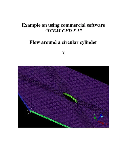
Example on using commercial software“ICEM CFD 5.1”Flow around a circular cylinderYTwo Dimensional problemsFlow around a circular cylinderProblem DescriptionAir flows across a cylinder with the uniform velocity in the wind tunnel. The length of the wind tunnel (fluid domain) has 25m long and 10 m height. The diameter of cylinder is 1m .Assumption and Boundary Conditions: 1. 2 dimensional problems 2. Steady state condition 3. The uniform flow velocity 4. No Heat transfer5. Neglect the gravitational force6. Constant air densityPre-processing stageIn this stage, we implement the “ICEM CFD” to perform the pre-processing work. The basic steps as follow:1. Establish geometry model2. Block the parts3. Generation the O grid4. Mesh the model and check quality of mesh5. Extrude the mesh6. R eset the BC’s (boundary conditions)7. Output toCreating Geometry1. Open ICEM CFDDouble Click the “ICEM CFD” Icon , afterwards, you can see the interface of the ICEM CFD.InletOutlet5DCylinderWall (SideB) Fluid domain5D20DWall (SideA)Open File>New Project…:2. Creating Geometry:A.PointsClick button “C reate Point ” and then click button “Explicit Coordinates ”Set the points in Cartesian coordinate system(X, Y, Z) with( X=0, Y=0, Z=0 ) respectively.Click “Apply” button and see the screen: a point is createdA tree widget can be seen at left of the screen (A) and (B)A BThe same method creates other points:X=-5; Y=5, -5X=20; Y=5, -5B.Draw line (curve)First of all see the tree widget, open Model>Geometry>Points by right buttonSelect Show Point Names and you can see the name ofeach point like the figure showed.Now you can create curvesClick button “Create/Modify Curve”Click button “Create Curve”Note: the left corner of the black screen: Select locationswith left button, middle=done, right=cancelSelect points by using left button of the mouse.Change the name of the Part with “INLET”:A BSelect and with left button (A),And draw a line with middle button “done”(B) and the INLET part is created in the tree widget.The same steps draw the curves named “OUTLET, SIDEA, SIDEB” with the 7and 8, and , POINTS.05 and respectively.We will see the line and the tree widgetDraw the cylinderClick button“Circle or arc from Center point and 2 points on plane ”.Set the Part with name “CYLINDER”Click button and select points “POINTS.00,POINTS.01, POINTS.03” with left button respectively(A).A BDraw the cylinder by middle button (B).See tree widget:Close Points name Use button to fit the window.Set the body and material.Click button “Create Body”Choose button “Mater ial Point”and select“Selected surfaces” in the “By Topology” menu.Change the name of the part with “FLUID”; open theShow Point Name of the tree widget and use selectand .The same way change the part name with “CYLINDER”and select and .Close Show Point Name and open the tree widget:Open the bodies and you can seeAt last, open the File>Geometry>Save Geometry As…Give it the name with “cylinder_2d”. Click “save”.Now we begin to block the model.Click button “Create Block”See the first one , choose the part with “FLUID”,from the pull down menu select “FLUID”And set the Initialize Blocks type with “2D Planar”Click “Apply” button.A BWe will see that the colors of figure are changed. From (A) to (B)See the tree widget: Model>BlockingThen create some assistant points with button “CreatePoint”{Y=0X=-0.45,-0.4,-0.35,-0.3,-0.25,-0.2,-0.15,-0.1,-0.5, 0.5,0.1, }{X=0}Now begin to block the regionClick button “Split Block”Then select button “Split Block”See the split method, select “Prescribed point”Use the put down menu to select the Prescribed point,Use the button firstly select the Edge “INLET” andsecondly select the Point “POINTS.03”.We will see the block line in the vertical direction of theINLET.Zoom the fiure.The same way we draw other block lines.From the to POINTS.04”See the tree widgetSelect the “Blocking” and select “Index Control”Model>Blocking: Index Control (using right button of the mouse) We can see at the right corner of the screenBy using button and we set I min=2 and see the figure The same way we set I max =3 , J min=2 , J max=3And the screen shown thatThe same way block again from to POINTS.44”:(A)(B)(C)A B CAfter block.See the tree widget: Model>Parts>VORFN :using the right button select “Add to Part”. Click button “Blocking Material”, Add Blocks to PartUsing select blocking regions and we can seeZoom the block regions (A).Select the blocks in the cylinder or attached the cylinder (B)(C).Using the middle button to set it OK , and you can see blow (D).Click button “Associate”ABD CSelect the associate edge to curve “Associate Edge toCurve”buttonUsing the choose the edge and curveChoosing edge:Select curves:Middle button:CBASet O gridClick button “Split Block”Click “Ogird Block”buttonSelect theSee the tree widget: Open Model>Parts>VORFNOpen the VORFN (A)AUsing button to selectin or attached the cylinder (B)(C)(D).B CD EUsing middle button to click “Apply”(E)Close “VORFN” from the tree widget (F)F GClick the “Reset”(G)Mesh the edgesClick button “Set Curve Mesh Size”Using button to select Curve(s):Choose Method with “Element count”Set the Number with 100 and click Apply.See the tree: close the Model>Geometry>points, and theModel>Blocking>edgesUsing right button to select Model>Geometry>Curves:Curve Node Spacing (by using right button)The same way set the “INLET” and “OUTLET” withnumber 100, the “SIDEA” and “SIDEB” with number 250.Click button “Pre-Mesh Params”Choose Blocking >Pre-Mesh ParamsClick button “Update Sizes” and keep default,Then click ApplySee tree open Model>Blocking>Pre_Mesh: Project faces(by using right button)And we will see a menuClick Yes.Now we will see the mesh of the model.Zoom it see the local partClose Geomery>Points and curves, and Blocking>Edges.Then open File>Mesh>Load from BlockingOpen File>Mesh>Save Mesh As…: and set the name with “cylinder_2d”Open File>Blocking>Save Blocking As…: Save block with the name “cylinder_2d”Check the quality of the meshClick button “Display Mesh Quality”Click ApplyWe can see no negatives mesh.Extrude meshClick button “Extrude Mesh”Use to select Elements:Method 1Click button “Select items in a part” and a menu appears:Click “All” and “Accept”Method 2A BPut the left button and drag it to select all the regions (A)(C). Click middle button to accept (B)Give the New volume part name “FLUID2D”, new side part name “SIDE”, new top par name “TOP”And set the Spacing type>spacing with ”, then ApplyCSo the mesh change a height in the Z direction (D)DBox ZoomE FClick button “Shaded Full Display”(E)(F) Check the quality of the extrude meshSee the tree widget:Close top “TOP” (B) Close “FLUID” (C)A BSet the new boundary conditionsSee the tree widget:Model>Parts: Create Part (by using the right button)Click “Create Part by Selection ” button From the pull down menu of the Part: select the “CYLINDER ” Using and left button drag the regionUsing middle button accepts it, so a new CYLINDER boundary condition has been set (C).CBACThe same way set the INLET, OUTLET, SIDEA and SIDEB boundary conditions. INLETThe Whole Boundary Conditions See the tree widget: CA BA Open Model>Parts>FLUID(B)B Open Model>Parts>TOP(C)CSix kinds of patterns Click File>Mesh>Save Mesh As… And save the new mesh with name “cylinder_2d_extrude”.Output the mesh file to CFXClick button “Select solver ” and choose “CFX-5” Click “Okay ”C B FE D AClick button “Write input”Keep default and click “Done”Then the Domain selection appearsKeep the Selected domains with “cylinder_2d_extrude.uns” and click “Done”.Now we will see the created files in working directions:From these files, we must note that only the file named “cfx5” can be inputted in to .1 The mesh is finished.Other examples:。
