汽车变速器的设计外文文献翻译、中英文翻译、外文翻译
- 格式:doc
- 大小:299.97 KB
- 文档页数:10
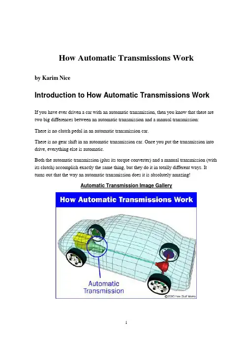
How Automatic Transmissions Workby Karim NiceIntroduction to How Automatic Transmissions WorkIf you have ever driven a car with an automatic transmission, then you know that there are two big differences between an automatic transmission and a manual transmission:There is no clutch pedal in an automatic transmission car.There is no gear shift in an automatic transmission car. Once you put the transmission into drive, everything else is automatic.Both the automatic transmission (plus its torque converter) and a manual transmission (with its clutch) accomplish exactly the same thing, but they do it in totally different ways. It turns out that the way an automatic transmission does it is absolutely amazing!Automatic Transmission Image GalleryIn this article, we'll work our way through an automatic transmission. We'll start with the key to the whole system: planetary gearsets. Then we'll see how the transmission is put together, learn how the controls work and discuss some of the intricacies involved in controlling a transmission.Just like that of a manual transmission, the automatic transmission's primary job is to allow the engine to operate in its narrow range of speeds while providing a wide range of output speeds.Photo courtesy DaimlerChryslerMercedes-Benz CLK, automatic transmission, cut-away modelWithout a transmission, cars would be limited to one gear ratio, and that ratio would have to be selected to allow the car to travel at the desired top speed. If you wanted a top speed of 80 mph, then the gear ratio would be similar to third gear in most manual transmission cars.You've probably never tried driving a manual transmission car using only third gear. If you did, you'd quickly find out that you had almost no acceleration when starting out, and at high speeds, the engine would be screaming along near the red-line. A car like this would wear out very quickly and would be nearly undriveable.So the transmission uses gears to make more effective use of the engine's torque, and to keep the engine operating at an appropriate speed.The key difference between a manual and an automatic transmission is that the manual transmission locks and unlocks different sets of gears to the output shaft to achieve the various gear ratios, while in an automatic transmission, the same set of gears produces all of the different gear ratios. The planetary gearset is the device that makes this possible in an automatic transmission.Let's take a look at how the planetary gearset works.Planetary Gearsets & Gear RatiosWhen you take apart and look inside an automatic transmission, you find a huge∙An ingenious planetary gearset∙ A set of bands to lock parts of a gearset∙ A set of three wet-plate clutches to lock otherparts of the gearset∙An incredibly odd hydraulic system that controlsthe clutches and bands∙ A large gear pump to move transmission fluidaroundThe center of attention is the planetary gearset. About the size of a cantaloupe, this one part creates all of the different gear ratios that the transmission can produce. Everything else in the transmission is there to help the planetary gearset do its thing. This amazing piece of gearing has appeared on HowStuffWorks before. You may recognize it from the electric screwdriver article. An automatic transmission contains two complete planetary gearsets folded together into one component. See How Gear Ratios Work for an introduction to planetary gearsets.From left to right: the ring gear, planet carrier, and two sun gearsAny planetary gearset has three main components:∙The sun gear∙The planet gears and the planet gears' carrier∙The ring gearEach of these three components can be the input, the output or can be held stationary. Choosing which piece plays which role determines the gear ratio for the gearset. Let's take a look at a single planetary gearset.One of the planetary gearsets from our transmission has a ring gear with 72 teeth and a sun gear with 30 teeth. We can get lots of different gear ratios out of this gearset.Also, locking any two of the three components together will lock up the whole device at a 1:1 gear reduction. Notice that the first gear ratio listed above is a reduction -- the output speed is slower than the input speed. The second is an overdrive -- the output speed is faster than the input speed. The last is a reduction again, but the output direction is reversed. There are several other ratios that can be gotten out of this planetary gear set, but these are the ones that are relevant to our automatic transmission. You can try these out in the animation below:So this one set of gears can produce all of these different gear ratios without having to engage or disengage any other gears. With two of these gearsets in a row, we can get the four forward gears and one reverse gear our transmission needs. We'll put the two sets of gears together in the next section.Compound Planetary GearsetThis automatic transmission uses a set of gears, called a compound planetary gearset, that looks like a single planetary gearset but actually behaves like two planetary gearsets combined. It has one ring gear that is always the output of the transmission, but it has two sun gears and two sets of planets.Let's look at some of the parts:How the gears in the transmission are put togetherLeft to right: the ring gear, planet carrier, and two sun gearsThe figure below shows the planets in the planet carrier. Notice how the planet on the right sits lower than the planet on the left. The planet on the right does not engage the ring gear -- it engages the other planet. Only the planet on the left engages the ring gear.Planet carrier: Note the two sets of planets.Next you can see the inside of the planet carrier. The shorter gears are engaged only by the smaller sun gear. The longer planets are engaged by the bigger sun gear and by the smaller planets.Inside the planet carrier: Note the two sets of planets.Automatic Transmission GearsFirst GearIn first gear, the smaller sun gear is driven clockwise by the turbine in the torque converter. The planet carrier tries to spin counterclockwise, but is held still by the one-way clutch (which only allows rotation in the clockwise direction) and the ring gear turns the output. The small gear has 30 teeth and the ring gear has 72, so the gear ratio is:Ratio = -R/S = - 72/30 = -2.4:1So the rotation is negative 2.4:1, which means that the output direction would be opposite the input direction. But the output direction is really the same as the input direction -- this is where the trick with the two sets of planets comes in. The first set of planets engages the second set, and the second set turns the ring gear; this combination reverses the direction. You can see that this would also cause the bigger sun gear to spin; but because that clutch is released, the bigger sun gear is free to spin in the opposite direction of the turbine (counterclockwise).Second GearT his transmission does something really neat in order to get the ratio needed for second gear. It acts like two planetary gearsets connected to each other with a common planet carrier.The first stage of the planet carrier actually uses the larger sun gear as the ring gear. So the first stage consists of the sun (the smaller sun gear), the planet carrier, and the ring (the larger sun gear).The input is the small sun gear; the ring gear (large sun gear) is held stationary by the band, and the output is the planet carrier. For this stage, with the sun as input, planet carrier as output, and the ring gear fixed, the formula is:1 + R/S = 1 + 36/30 = 2.2:1The planet carrier turns 2.2 times for each rotation of the small sun gear. At the second stage, the planet carrier acts as the input for the second planetary gear set, the larger sun gear (which is held stationary) acts as the sun, and the ring gear acts as the output, so the gear ratio is:1 / (1 + S/R) = 1 / (1 + 36/72) = 0.67:1To get the overall reduction for second gear, we multiply the first stage by the second, 2.2 x 0.67, to get a 1.47:1 reduction. This may sound wacky, but it works.Third GearMost automatic transmissions have a 1:1 ratio in third gear. You'll remember from the previous section that all we have to do to get a 1:1 output is lock together any two of the three parts of the planetary gear. With the arrangement in this gearset it is even easier -- all we have to do is engage the clutches that lock each of the sun gears to the turbine.If both sun gears turn in the same direction, the planet gears lockup because they can only spin in opposite directions. This locks the ring gear to the planets and causes everything to spin as a unit, producing a 1:1 ratio.OverdriveBy definition, an overdrive has a faster output speed than input speed. It's a speed increase -- the opposite of a reduction. In this transmission, engaging the overdrive accomplishes two things at once. If you read How Torque Converters Work, you learned about lockup torque converters. In order to improve efficiency, some cars have a mechanism that locksup the torque converter so that the output of the engine goes straight to the transmission.In this transmission, when overdrive is engaged, a shaft that is attached to the housing of the torque converter (which is bolted to the flywheel of the engine) is connected by clutch to the planet carrier. The small sun gear freewheels, and the larger sun gear is held by the overdrive band. Nothing is connected to the turbine; the only input comes from the converter housing. Let's go back to our chart again, this time with the planet carrier for input, the sun gear fixed and the ring gear for output.Ratio = 1 / (1 + S/R) = 1 / ( 1 + 36/72) = 0.67:1So the output spins once for every two-thirds of a rotation of the engine. If the engine is turning at 2000 rotations per minute (RPM), the output speed is 3000 RPM. This allows cars to drive at freeway speed while the engine speed stays nice and slow.ReverseReverse is very similar to first gear, except that instead of the small sun gear being driven by the torque converter turbine, the bigger sun gear is driven, and the small one freewheels in the opposite direction. The planet carrier is held by the reverse band to the housing. So, according to our equations from the last page, we have:Ratio = -R/S = 72/36 = 2.0:1So the ratio in reverse is a little less than first gear in this transmission.Gear RatiosThis transmission has four forward gears and one reverse gear. Let's summarize the gear ratios, inputs and outputs:After reading these sections, you are probably wondering how the different inputs get connected and disconnected. This is done by a series of clutches and bands inside the transmission. In the next section, we'll see how these work.Clutches and Bands in an Automatic TransmissionIn the last section, we discussed how each of the gear ratios is created by the transmission. For instance, when we discussed overdrive, we said:In this transmission, when overdrive is engaged, a shaft that is attached to the housing of the torque converter (which is bolted to the flywheel of the engine) is connected by clutch to the planet carrier. The small sun gear freewheels, and the larger sun gear is held by the overdrive band. Nothing is connected to the turbine; the only input comes from the converter housing.To get the transmission into overdrive, lots of things have to be connected and disconnected by clutches and bands. The planet carrier gets connected to the torque converter housing by a clutch. The small sun gets disconnected from the turbine by a clutch so that it can freewheel. The big sun gear is held to the housing by a band so that it could not rotate. Each gear shift triggers a series of events like these, with different clutches and bands engaging and disengaging. Let's take a look at a band.BandsIn this transmission there are two bands. The bands in a transmission are, literally, steel bands that wrap around sections of the gear train and connect to the housing. They are actuated by hydraulic cylinders inside the case of the transmission.One of the bandsIn the figure above, you can see one of the bands in the housing of the transmission. The gear train is removed. The metal rod is connected to the piston, which actuates the band.The pistons that actuate the bands are visible here.Above you can see the two pistons that actuate the bands. Hydraulic pressure, routed into the cylinder by a set of valves, causes the pistons to push on the bands, locking that part of the gear train to the housing.The clutches in the transmission are a little more complex. In this transmission there are four clutches. Each clutch is actuated by pressurized hydraulic fluid that enters a piston inside the clutch. Springs make sure that the clutch releases when the pressure is reduced.Below you can see the piston and the clutch drum. Notice the rubber seal on the piston -- this is one of the components that is replaced when your transmission gets rebuilt.One of the clutches in a transmissionThe next figure shows the alternating layers of clutch friction material and steel plates. The friction material is splined on the inside, where it locks to one of the gears. The steel plate is splined on the outside, where it locks to the clutch housing. These clutch plates are also replaced when the transmission is rebuilt.The clutch platesThe pressure for the clutches is fed through passageways in the shafts. The hydraulic system controls which clutches and bands are energized at any given moment.FROM: /automatic-transmission.htm自动变速器的工作原理耐斯·卡瑞姆介绍自动变速器的工作原理如果你驾驶过带有自动变速器的汽车,那么你一定知道手动变速器与自动变速器之间存在两个很大的区别:·自动变速器中没有离合器踏板·自动变速器中没有换档手柄,一旦让变速器传递动力,那么接下来的一切都是自动完成的了。
Transmission (mechanics)A transmission or gearbox provides speed and torque conversions from a rotating power source to another device using gear ratios. In British English the term transmission refers to the whole drive train, including gearbox, clutch, prop shaft (for rear-wheel drive), differential and final drive shafts. The most common use is in motor vehicles, where the transmission adapts the output of the internal combustion engine to the drive wheels. Such engines need to operate at a relatively high rotational speed, which is inappropriate for starting, stopping, and slower travel. The transmission reduces the higher engine speed to the slower wheel speed, increasing torque in the process. Transmissions are also used on pedal bicycles, fixed machines, and anywhere else rotational speed and torque needs to be adapted.Often, a transmission will have multiple gear ratios (or simply "gears"), with the ability to switch between them as speed varies. This switching may be done manually (by the operator), or automatically. Directional (forward and reverse) control may also be provided. Single-ratio transmissions also exist, which simply change the speed and torque (and sometimes direction) of motor output.In motor vehicle applications, the transmission will generally be connected to the crankshaft of the engine. The output of the transmissionis transmitted via driveshaft to one or more differentials, which in turn drive the wheels. While a differential may also provide gear reduction, its primary purpose is to change the direction of rotation.Conventional gear/belt transmissions are not the only mechanism for speed/torque adaptation. Alternative mechanisms include torque converters and power transformation (e.g., diesel-electric transmission, hydraulic drive system, etc.). Hybrid configurations also exist. ExplanationEarly transmissions included the right-angle drives and other gearing in windmills, horse-powered devices, and steam engines, in support of pumping, milling, and hoisting.Most modern gearboxes are used to increase torque while reducing the speed of a prime mover output shaft (e.g. a motor crankshaft). This means that the output shaft of a gearbox will rotate at slower rate than the input shaft, and this reduction in speed will produce a mechanical advantage, causing an increase in torque. A gearbox can be setup to do the opposite and provide an increase in shaft speed with a reduction of torque. Some of the simplest gearboxes merely change the physical direction in which power is transmitted.Many typical automobile transmissions include the ability to select one of several different gear ratios. In this case, most of the gear ratios (often simply called "gears") are used to slow down the output speed ofthe engine and increase torque. However, the highest gears may be "overdrive" types that increase the output speed.UsesGearboxes have found use in a wide variety of different—often stationary—applications, such as wind turbines.Transmissions are also used in agricultural, industrial, construction, mining and automotive equipment. In addition to ordinary transmission equipped with gears, such equipment makes extensive use of the hydrostatic drive and electrical adjustable-speed drives.SimpleThe simplest transmissions, often called gearboxes to reflect their simplicity (although complex systems are also called gearboxes in the vernacular), provide gear reduction (or, more rarely, an increase in speed), sometimes in conjunction with a right-angle change in direction of the shaft (typically in helicopters, see picture). These are often used on PTO-powered agricultural equipment, since the axial PTO shaft is at odds with the usual need for the driven shaft, which is either vertical (as with rotary mowers), or horizontally extending from one side of the implement to another (as with manure spreaders, flail mowers, and forage wagons). More complex equipment, such as silage choppers and snowblowers, have drives with outputs in more than one direction.The gearbox in a wind turbine converts the slow, high-torquerotation of the turbine into much faster rotation of the electrical generator. These are much larger and more complicated than the PTO gearboxes in farm equipment. They weigh several tons and typically contain three stages to achieve an overall gear ratio from 40:1 to over 100:1, depending on the size of the turbine. (For aerodynamic and structural reasons, larger turbines have to turn more slowly, but the generators all have to rotate at similar speeds of several thousand rpm.) The first stage of the gearbox is usually a planetary gear, for compactness, and to distribute the enormous torque of the turbine over more teeth of the low-speed shaft. Durability of these gearboxes has been a serious problem for a long time.Regardless of where they are used, these simple transmissions all share an important feature: the gear ratio cannot be changed during use. It is fixed at the time the transmission is constructed.For transmission types that overcome this issue, see Continuously Variable Transmission, also known as CVT.Multi-ratio systemsMany applications require the availability of multiple gear ratios. Often, this is to ease the starting and stopping of a mechanical system, though another important need is that of maintaining good fuel efficiency. Automotive basicsThe need for a transmission in an automobile is a consequence of the characteristics of the internal combustion engine. Engines typicallyoperate over a range of 600 to about 7000 revolutions per minute (though this varies, and is typically less for diesel engines), while the car's wheels rotate between 0 rpm and around 1800 rpm.Furthermore, the engine provides its highest torque outputs approximately in the middle of its range, while often the greatest torque is required when the vehicle is moving from rest or traveling slowly. Therefore, a system that transforms the engine's output so that it can supply high torque at low speeds, but also operate at highway speeds with the motor still operating within its limits, is required. Transmissions perform this transformation.Many transmissions and gears used in automotive and truck applications are contained in a cast iron case, though more frequently aluminium is used for lower weight especially in cars. There are usually three shafts: a mainshaft, a countershaft, and an idler shaft.The mainshaft extends outside the case in both directions: the input shaft towards the engine, and the output shaft towards the rear axle (on rear wheel drive cars- front wheel drives generally have the engine and transmission mounted transversely, the differential being part of the transmission assembly.) The shaft is suspended by the main bearings, and is split towards the input end. At the point of the split, a pilot bearing holds the shafts together. The gears and clutches ride on the mainshaft, the gears being free to turn relative to the mainshaft except when engagedby the clutches.Types of automobile transmissions include manual, automatic or semi-automatic transmission.ManualMain article: Manual transmissionManual transmission come in two basic types:a simple but rugged sliding-mesh or unsynchronized / non-synchronous system, where straight-cut spur gear sets are spinning freely, and must be synchronized by the operator matching engine revs to road speed, to avoid noisy and damaging "gear clash", and the now common constant-mesh gearboxes which can include non-synchronised, or synchronized / synchromesh systems, where diagonal cut helical (and sometimes double-helical) gear sets are constantly "meshed" together, and a dog clutch is used for changing gears. On synchromesh boxes, friction cones or "synchro-rings" are used in addition to the dog clutch.The former type is commonly found in many forms of racing cars, older heavy-duty trucks, and some agricultural equipment.Manual transmissions are the most common type outside North America and Australia. They are cheaper, lighter, usually give better performance, and fuel efficiency (although the latest sophisticated automatic transmissions may yield results slightly better than the ones yielded by manual transmissions). It is customary for new drivers to learn, and betested, on a car with a manual gear change. In Malaysia, Denmark and Poland all cars used for testing (and because of that, virtually all those used for instruction as well) have a manual transmission. In Japan, the Philippines, Germany, Italy, Israel, the Netherlands, Belgium, New Zealand, Austria, Bulgaria, the UK, Ireland, Sweden, Estonia, France, Spain, Switzerland, the Australian states of Victoria and Queensland, Finland and Lithuania, a test pass using an automatic car does not entitle the driver to use a manual car on the public road; a test with a manual car is required.Manual transmissions are much more common than automatic transmissions in Asia, Africa, South America and Europe.Most manual transmissions include both synchronized and unsynchronized gearing, such as a reverse gear and a low-speed "granny gear", both of which can only be shifted into when stopped. Shifting from granny gear to a low synchronized gear is generally available while in motion, while shifting out of reverse to any other gear typically requires the vehicle to be stopped.Non-synchronousMain article: Non-synchronous transmissionsThere are commercial applications engineered with designs taking into account that the gear shifting will be done by an experienced operator. They are a manual transmission, but are known as non-synchronized transmissions. Dependent on country of operation, many local, regional,and national laws govern the operation of these types of vehicles (see Commercial Driver's License). This class may include commercial, military, agricultural, or engineering vehicles. Some of these may use combinations of types for multi-purpose functions. An example would be a PTO, or power-take-off gear. The non-synchronous transmission type requires an understanding of gear range, torque, engine power, and multi-functional clutch and shifter functions. Also see Double-clutching, and Clutch-brake sections of the main article at non-synchronous transmissionsAutomaticMain article: Automatic transmissionEpicyclic gearing or planetary gearing as used in an automatic transmission.Most modern North American and Australian and many larger, high specification European and Japanese cars have an automatic transmission that will select an appropriate gear ratio without any operator intervention. They primarily use hydraulics to select gears, depending on pressure exerted by fluid within the transmission assembly. Rather than using a clutch to engage the transmission, a fluid flywheel, or torque converter is placed in between the engine and transmission. It is possible for the driver to control the number of gears in use or select reverse, though precise control of which gear is in use may or may not be possible.Automatic transmissions are easy to use. However, in the past, automatic transmissions of this type have had a number of problems; they were complex and expensive, sometimes had reliability problems (which sometimes caused more expenses in repair), have often been less fuel-efficient than their manual counterparts (due to "slippage" in the torque converter), and their shift time was slower than a manual making them uncompetitive for racing. With the advancement of modern automatic transmissions this has changed.Attempts to improve the fuel efficiency of automatic transmissions include the use of torque converters which lock up beyond a certain speed, or in the higher gear ratios, eliminating power loss, and overdrive gears which automatically actuate above certain speeds; in older transmissions both technologies could sometimes become intrusive, when conditions are such that they repeatedly cut in and out as speed and such load factors as grade or wind vary slightly. Current computerized transmissions possess very complex programming to both maximize fuel efficiency and eliminate any intrusiveness.For certain applications, the slippage inherent in automatic transmissions can be advantageous; for instance, in drag racing, the automatic transmission allows the car to be stopped with the engine at a high rpm (the "stall speed") to allow for a very quick launch when the brakes are released; in fact, a common modification is to increase the stallspeed of the transmission. This is even more advantageous for turbocharged engines, where the turbocharger needs to be kept spinning at high rpm by a large flow of exhaust in order to keep the boost pressure up and eliminate the turbo lag that occurs when the engine is idling and the throttle is suddenly openedSemi-automaticMain article: Semi-automatic transmissionThe creation of computer control also allowed for a sort of cross-breed transmission where the car handles manipulation of the clutch automatically, but the driver can still select the gear manually if desired. This is sometimes called a "clutchless manual," or "automated manual" transmission. Many of these transmissions allow the driver to give full control to the computer. They are generally designed using manual transmission "internals", and when used in passenger cars, have synchromesh operated helical constant mesh gear sets.Specific type of this transmission includes: Easytronic, and Geartronic.A "dual-clutch" transmission uses two sets of internals which are alternately used, each with its own clutch, so that only the clutches are used during the actual "gearchange".Specific type of this transmission includes: Direct-Shift Gearbox.There are also sequential transmissions which use the rotation of adrum to switch gears.Bicycle gearingMain articles: Bicycle gearing, Derailleur gears, and Hub gear Bicycles usually have a system for selecting different gear ratios. There are two main types: derailleur gears and hub gears. The derailleur type is the most common, and the most visible, using sprocket gears. Typically there are several gears available on the rear sprocket assembly, attached to the rear wheel. A few more sprockets are usually added to the front assembly as well. Multiplying the number of sprocket gears in front by the number to the rear gives the number of gear ratios, often called "speeds".Hub gears use epicyclic gearing and are enclosed within the axle of the rear wheel. Because of the small space, they typically offer fewer different speeds, although at least one has reached 14 gear ratios and Fallbrook Technologies manufactures a transmission with technically infinite ratios.Causes for failure of bicycle gearing include: worn teeth, damage caused by a faulty chain, damage due to thermal expansion, broken teeth due to excessive pedaling force, interference by foreign objects, and loss of lubrication due to negligence.Uncommon typesDual clutch transmissionMain article: Dual clutch transmissionThis arrangement is also sometimes known as a direct shift gearbox or powershift gearbox. It seeks to combine the advantages of a conventional manual shift with the qualities of a modern automatic transmission by providing different clutches for odd and even speed selector gears. When changing gear, the engine torque is transferred from one gear to the other continuously, so providing gentle, smooth gear changes without either losing power or jerking the vehicle. Gear selection may be manual, automatic (depending on throttle/speed sensors), or a 'sports' version combining both options.Continuously variableMain article: Continuously variable transmissionThe Continuously Variable Transmission (CVT) is a transmission in which the ratio of the rotational speeds of two shafts, as the input shaft and output shaft of a vehicle or other machine, can be varied continuously within a given range, providing an infinite number of possible ratios. The continuously variable transmission (CVT) should not be confused with the Infinitely Variable Transmission (IVT) (See below).The other mechanical transmissions described above only allow a few different gear ratios to be selected, but this type of transmission essentially has an infinite number of ratios available within a finite range. The continuously variable transmission allows the relationship betweenthe speed of the engine and the speed of the wheels to be selected within a continuous range. This can provide even better fuel economy if the engine is constantly running at a single speed. The transmission is in theory capable of a better user experience, without the rise and fall in speed of an engine, and the jerk felt when poorly changing gears. Infinitely variableThe IVT is a specific type of CVT that has an infinite range of input/output ratios in addition to its infinite number of possible ratios; this qualification for the IVT implies that its range of ratios includes a zero output/input ratio that can be continuously approached from a defined 'higher' ratio. A zero output implies an infinite input, which can be continuously approached from a given finite input value with an IVT. [Note: remember that so-called 'low' gears are a reference to low ratios of output/input, which have high input/output ratios that are taken to the extreme with IVT's, resulting in a 'neutral', or non-driving 'low' gear limit.]Most (if not all) IVT's result from the combination of a CVT with an epicyclic gear system (which is also known as a planetary gear system) that facilitates the subtraction of one speed from another speed within the set of input and planetary gear rotations. This subtraction only needs to result in a continuous range of values that includes a zero output; the maximum output/input ratio can be arbitrarily chosen from infinitepractical possibilities through selection of extraneous input or output gear, pulley or sprocket sizes without affecting the zero output or the continuity of the whole system. Importantly, the IVT is distinguished as being 'infinite' in its ratio of high gear to low gear within its range; high gear is infinite times higher than low gear. The IVT is always engaged, even during its zero output adjustment.The term 'infinitely variable transmission' does not imply reverse direction, disengagement, automatic operation, or any other quality except ratio selectability within a continuous range of input/output ratios from a defined minimum to an undefined, 'infinite' maximum. This means continuous range from a defined output/input to zero output/input ratio. Electric variableThe Electric Variable Transmission (EVT) is a transmission that achieves CVT action and in addition can use separate power inputs to produce one output. An EVT usually is executed in design with an epicyclic differential gear system (which is also known as a planetary gear system). The epicyclic differential gearing performs a "power-split" function, directly connecting a portion of the mechanical power directly through the transmission and splitting off a portion for subsequent conversion to electrical power via a motor/generator. Hence, the EVT is called a Power Split Transmission (PST) by some.The directly connected portion of the power travelling through theEVT is referred to as the "mechanical path". The remaining power travels down the EVT's "electrical path". That power may be recombined at the output of the transmission or stored for later, more opportune use via a second motor/generator (and energy storage device) connected to the transmission output.The pair of motor/generators forms an Electric Transmission in its own right, but at a lower capacity, than the EVT it is contained within. Generally the Electric Transmission capacity within the EVT is a quarter to a half of the capacity of the EVT. Good reasons to use an EVT instead of an equivalently-sized Electrical transmission is that the mechanical path of the EVT is more compact and efficient than the electrical path.The EVT is the essential method for transmitting power in some hybrid vehicles, enabling an Internal Combustion Engine (ICE) to be used in conjunction with motor/generators for vehicle propulsion, and having the ability to control the portion of the mechanical power used directly for propelling the vehicle and the portion of mechanical power that is converted to electric power and recombined to drive the vehicle.The EVT and power sources are controlled to provide a balance between the power sources that increases vehicle fuel economy while providing advantageous performance when needed. The EVT may also be used to provide electrically generated power to charge large storage batteries for subsequent electric motor propulsion as needed, or to convertvehicle kinetic energy to electricity through 'regenerative braking' during deceleration. Various configurations of power generation, usage and balance can be implemented with a EVT, enabling great flexibility in propelling hybrid vehicles.The Toyota single mode hybrid and General Motor 2 Mode hybrid are production systems that use EVTs. The Toyota system is in the Prius, Highlander, and Lexus RX400h and GS450h models. The GM system is the Allison Bus hybrid powertrains and are in the Tahoe and Yukon models. The Toyota system uses one power-split epicyclic differential gearing system over all driving conditions and is sized with an electrical path rated at approximately half the capacity of the EVT. The GM system uses two different EVT ranges: one designed for lower speeds with greater mechanical advantage, and one designed for higher speeds, and the electrical path is rated at approximately a quarter of the capacity of the EVT. Other arrangements are possible and applications of EVT's are growing rapidly in number and variety.EVT's are capable of continuously modulating output/input speed ratios like mechanical CVT's, but offer the distinct difference and benefit of being able to also apportion power from two different sources to one output.HydrostaticSee also Continuously variable transmission > Hydrostatic CVTsHydrostatic transmissions transmit all power hydraulically, using the components of hydraulic machinery. Hydrostatic transmissions do not make use of the hydrodynamic forces of the fluid flow. There is no solid coupling of the input and output. The transmission input drive is a central hydraulic pump and final drive unit(s) is/are a hydraulic motor, or hydraulic cylinder (see:swashplate. Both components can be placed physically far apart on the machine, being connected only by flexible hoses. Hydrostatic drive systems are used on excavators, lawn tractors, forklifts, winch drive systems, heavy lift equipment, agricultural machinery, etc. An arrangement for motor-vehicle transmission was probably used on the Ferguson F-1 P99 racing car in about 1961.The Human Friendly Transmission of the Honda DN-01 is hydrostatic.HydrodynamicIf the hydraulic pump and/or hydraulic motor make use of the hydrodynamic effects of the fluid flow, i.e. pressure due to a change in the fluid's momentum as it flows through vanes in a turbine. The pump and motor usually consist of rotating vanes without seals and are typically placed in close proximity. The transmission ratio can be made to vary by means of additional rotating vanes, an effect similar to varying the pitch of an airplane propeller.The torque converter in most automotive automatic transmissions is,in itself, a hydrodynamic transmission.It was possible to drive the Dynaflow transmission without shifting the mechanical gears.Hydrodynamic transmissions are used in many passenger rail vehicles. In this application the advantage of smooth power delivery may outweigh the reduced efficiency caused by turbulence energy losses in the fluid.ElectricElectric transmissions convert the mechanical power of the engine(s) to electricity with electric generators and convert it back to mechanical power with electric motors. Electrical or electronic adjustable-speed drive control systems are used to control the speed and torque of the motors. If the generators are driven by turbines, such arrangements are called turbo-electric. Likewise installations powered by diesel-engines are called diesel-electric. Diesel-electric arrangements are used on many railway locomotives, ships and large mining trucks.。
外文翻译Auto TransmissionFirst, an overview of automotive transmission and the development trendAutomobile available more than a century, especially from the mass production of motor vehicles and the automotive industry since the development of large, Car has been the economic development of the world for mankind to enter the modern life and have had a tremendous impact on the immeasurable, The progress of human society has made indelible contributions to the great, epoch-making set off arevolution. From From the vehicle as a power plant using internal combustion engine to start, auto transmission has become an important component. Is Generation is widely used in automotive reciprocating piston internal combustion engine with a small size, light weight, reliable operation and the use of The advantages of convenience, but its torque and speed range of smaller changes, and complex condition requires the use of motor vehicles Traction and the speed can be considerable changes in the scope. Therefore, its performance and vehicle dynamics and economy of There are large inter-contradictions, which contradictions of modern automotive internal combustion engine by itself is insoluble. Because Here, in the automotive power train set up the transmission and main reducer in order to achieve the purpose of deceleration by moment. Speed The main function of performance: ⑴ change gear ratio of motor vehicles, and expand the wheel drive torque and rotational speed of the Fan Wai, in order to adapt to constantly changing driving cycle, while the engine in the most favorable conditions within the scope of work; ⑵no change in the direction of engine rotation, under the premise of the realization of cars driving back; ⑶the realization of the free, temporary Interruption of power transmission, in order to be able to start the engine, idling, etc.. V ariable-speed drive transmission by the manipulation of institutions and agencies. Change the transmission ratio by way of transmission is divided into There are class-type, non-stage and multi-purpose three. Have class most widely used transmission. It uses gear drive, with a number of transmission ratio setting. Stepless transmission Continuously V ariable Transmission (CVT) transmission ratio of a certain The framework of multi-level changes may be unlimited, there is a common type of power and torque (dynamic fluid-type) and so on. Continuously V ariable Transmission Transmission development is the ultimate goal, because only it can make the most economical engine in working condition Can provide the best vehicle fuel economy and optimal power in order to provide the most comfortable By the feeling. Today's CVT is a typical representative of the CVTand IVT, however as a result of the reliability of Poor, non-durable materials and high cost issues, development is not very good. Comprehensive refers to transmission torque converter and the mechanical components have the level of transmission variable hydraulic mechanical Speed, the transmission ratio can be between the maximum and minimum range of a few discontinuous change for no class, but its Significantly lower transmission efficiency than the efficiency of gear drives. 2 By manipulation, transmission control type can be divided into mandatory, automatic and semi-automatic control to manipulate three - Species . Mandatory on the driver to manipulate the direct transmission gear shift control for the majority of motor vehicles used Also known as Manual Transmission Manual Transmission (MT). Automatic transmission control selection of the transmission ratio (transmission) is carried out automatically. Just add the driver to manipulate Speed pedal, you can control the speed, also known as Automatic Transmission Automatic Transmission (A T). It is According to the speed and load (throttle pedal travel) for two-parameter control, stall in accordance with the above two Parameters to automatically take-off and landing.A T and MT in common is that they are level transmission, but A T According to the speed of the speed shift automatically, you can eliminate the manual transmission "setback" of the shift feel. However, A T also have many drawbacks, such as body complex, mechanical efficiency is not high, high cost, reliability and control Sensitivity remains to be increasing . AMT (Automated Mechanical Transmission) is in the traditional dry clutch and manual transmission gear based on the transformation of form, mainly to change the part of the manual gearshift control. That is, the overall structure of the MT cases the same switch to electronically controlled automatic transmission to achieve. Semi-automatic control, there are two forms of transmission. A number of stalls is a common automatic control, and the remaining stalls manipulated by the driver; the other is pre-style, that is, pre-selected pilot stalls, the clutch pedal in the down or release the accelerator pedal, the for retirement or an electromagnetic device to shift the hydraulic device. In recent years, with advances in vehicle technology and road traffic density increased, the performance requirements of the transmission is also getting higher and higher. A large number of automotive engineers in improving the performance of automobile transmission study a great deal of effort devoted to the rapid transmission of technology development, such as A T, AMT, DCT, CVT and the emergence of IVT.2003 Hyundai A T, AMT, DCT, CVT forum reached a consensus on the following:in the next Development, MT will continue to be the most widely used automotive transmission, AMT will increase the proportion of the application, A T also Will occupy a large market share, CVT's use of certain limitations, can only be due to a number of small displacement Car, DCT (dual clutch transmission) will also be the budding growth. From 2003 to now, vehicle speed Thedevelopment of devices and the forum basically the consensus reached by consensus. By comparing the analysis, the traditional mechanical transmission is still the most widely used vehicle change Speed. Although it has many shortcomings, such as shifting the impact of large, bulky, cumbersome to manipulate and so on; however, it also There are many advantages, such as high transmission efficiency, reliable operation, long life, manufacturing processes mature and low cost. Therefore, if we can improve the mechanical transmission of the above-mentioned shortcomings, it still has great room for development.Second, Manual Transmission Fault DiagnosisManual transmission at the beginning of the fault diagnosis prior toFailure to confirm from other parts is not: to check the tire And wheels, to confirm the normal tire pressure, and the wheel is flat V alue of; to confirm instead of noise and vibration from the engine. Clutch , And steering and suspension, etc..(A), skip file1. PhenomenonV ehicle acceleration, deceleration, climbing or severe vehicle vibration, the gear lever neutral position automatically jump.2. Reasons① self-locking device of the ball did not enter the grooves or linked file does not meet the full-gear tooth meshing long;② self-locking device worn groove ball or serious, self-locking spring is too soft or broken fatigue;③ gear along the direction of tooth wear as a long cone-shaped;④ one or two too松旷shaft bearing, so that one or two three-axis and the crankshaft axis of the heart or different transmission and clutch shell shell bonding plane of the vertical axis the relative change in the crankshaft;⑤ Second Gear axis often axial or radial gap is too large;⑥ the axis of axial or radial gap is too large.3. Fault diagnosis and troubleshootingJump to file stalls Unascertained: After taking heat the entire vehicle, increase the use of continuous, slow approach to road test each file is determined.Will jump to the gear lever hanging file stalls the engine off, transmission cover removed carefully to observe the mating dance gear case file.① engagement does not meet the length, then the resulting fault;② to reach a total length of engagement, should continue to check;③ check mating wear parts: wear into a cone, then failure may be caused by;④ check b-axis of the gear profile and the axis of the axial and radial clearance, clearance is too large, then failure may be caused by;⑤ check self-locking devices, locking devices, if only a very small dynamic resistance, and even feel the ball is not plugged groove (the transmission cover caught in the vice, the hand-shaking shift stroke), the fault for the bad performance of self-locking ; Otherwise, the fault for the clutch and gearbox shell bonding plane and the vertical axis of the crankshaft caused by changes.(B), arbitrary files1. PhenomenonTechnical condition in the clutch normal circumstances, transmission at the same time put up or two files linked to the need to stall, the results linked to other stalls.2. Reasons① interlocking device failure: if the fork shaft, pin or interlocking interlocking ball too much wear and tear, etc.;② the bottom of the arc gear face wear and tear is too large or fork axis of the allocated blocks wear groove is too large;③ball pin gear lever broken or the ball-hole, ball松旷wear too. In short arbitrary file transmission is mainly due to institutional failure manipulation.3. Fault diagnosis and troubleshooting① linked to the need to stall, the results linked to the other stalls: rocking gear lever, to check their point of view before, if in excess of the normal range, while the lower end of failure by the gear lever ball pin and the positioning groove ball with or松旷, the ball is too large holes caused by wear and tear. Swung shift 360 °, compared with a broken pin.② If the pendulum angle to normal, still not on, or linked to more than picking file, then the lower end of failure by the gear lever away from the limitations arising from the groove in (due to break away from the bottom of the arc-shaped guide groove face wear and tear or wear).③ At the same time linked to the two files: the fault caused by the interlocking device failure.(C), the difficulties linked to files1. PhenomenonClutch technical condition, but can not be linked smoothly linked file into the stalls, often percussive sound gear.2. Reasons① synchronizer failure;② Bending fork shaft, locking the spring strong, ball injury, etc.;③ a shaft or a spline shaft bending injury;④ inadequate or excessive gear oil, gear oil does not meet the specifications.3. Fault diagnosis and troubleshooting①Synchronizer check whether the fall to pieces, cone ring is conical spiral groove wear, whether worn slider, spring is too soft, such as elastic.② If the Synchronizer normal, check whether the bending of a shaft, spline wear is severe.③ check whether the mobile axis normal fork.(D), abnormal sound transmission1. PhenomenonTransmission refers to transmission work abnormal sound when the sound is not normal.2. Reasons1) abnormal sound gearGear wear off very thin gap is too large, the impact of running in; bad tooth meshing, such as the repair did not replace the gear pairs. New and old gear with the gear mesh can not be correct; tooth metal fatigue spalling or damage to individual teeth broken; gear and the spline shaft with松旷, or the axial gear clearance is too large; axis caused by bending or bearing松旷space to change gears.2) Bearing ringSerious bearing wear; Bearing (outer) ring with the journal blocks (holes) with the loose; Ball Bearing Ma break-up or a point of ablation.3) ring made for other reasonsSuch as the transmission within缺油, lubricants have been thin, too thick or quality deterioration; transmission into the foreign body inside; some loose bolts fastening; odometer or the odometer shaft ring gear, such as fat.3. Troubleshooting①transmission issued metal dry friction sound, which is缺油and the poor quality of oil. Refueling and inspection should be the quality of oil, if necessary, replacement.② for moving into a file if the sound obvious, namely, the profile of gear tooth wear; If the occurrence of cyclical noise, while damage to individual teeth.③when the ring gap, and riding the clutch pedal under the noise disappeared after the general axis is a before and after the bearing or regular engagement ring gear; if any files are changed into the ring, after more than two-axis bearing ring.④transmission occurs when a sudden impact the work of sound, most of the tooth was broken and should be removed timely transmission inspection cover to prevent mechanicaldamage.⑤moving, only for transmission of a file into the ring gear made in the above-mentioned good premise, it should check with improper gear mesh, if necessary, should be re-assembling a pair of new gear. In addition, it may be synchronizer gear wear or damage should be repaired or replaced depending on the circumstances.⑥ when shifting gear ring made of impact, it may be the clutch or the clutch pedal can not be separated from stroke is incorrect, damaged synchronizer, excessive idling, gear improperly adjusted or tight-oriented, such as Bush. In such cases, to check whether the separation of the clutch, and then adjust the idle speed or the gear lever, respectively, the location, inspection-oriented with the bearing bushing and separation tightness.If excluded from the above examinations, the transmission is still made ring, should check the shaft bearings and shaft hole with the situation, bearing the state of their own technology, etc.; as well, and then view the odometer shaft and ring gear is made and, if necessary, be repaired or replacement.(E), transmission oil1. PhenomenonAround the transmission gear lubricants, transmission gear box to reduce the fuel can be judged as lubricant leakage.2. Reasons and troubleshooting① improper oil selection, resulting in excessive foam, or the volume too much oil, when in need of replacement or adjust the lubricant oil;② side cover is too loose, damaged gaskets, oil seal damage, damage to seals and oil seals should be replaced with new items;③ release and transmission oil tank and side cover fixed bolts loosening, tightening torque should be required;④ broken gear-housing shell or extended wear and tear caused by oil spills, must be replaced;⑤ odometer broken loose gear limit device must be locked or replaced; gear oil seal oil seal oil should be replaced.Third, the maintenance manual gearboxSantana is now as an example:Santana used to manually synchronize the entire, multi-stage gear transmission, there are four forward one block and reverse gear. Block are forward-lock synchronizer ring inertial, body-wide shift synchronizer nested engagement with a reasonable structure, the layout of a compact, reliable, long life and so on. However, if the use and maintenance is not the right way to do so, failure mayoccur at any time.The proper use of Synchronizer:1, the use of addition and subtraction block off both feet. Block addition and subtraction, if the clutch with one foot, then the speed at the time of addition and subtraction block must be correct, the timing should be appropriate and, if necessary, to addition and subtraction can be blocked off both feet, so that addition and subtraction method can reduce the block with Gear speed difference between the circumference, thereby reducing wear and tear Synchronizer to extend the life of Synchronizer.2, prohibited the use of tap-shift gear lever when the method (that is, a push of the operation of a song). Hand should always hold down the shift, this can greatly reduce the synchronizer sliding lock Moreton Central time and reduce wear and tear.3, no state in the gap off the use of force挂挡synchronizer start the engine. Moment of inertia as a great engine, the friction torque Synchronizer also small, so the time synchronization process is very long, so that lock ring temperature increased sharply, it is easy to burn synchronizer.4, is strictly prohibited by synchronizer clutch instead of the initial (that is, the use of non-use of the clutch friction synchronizer start挂挡role), control speed and braking.The correct use of lubricants:Santana at the factory, the transmission has been added to the quality of lubricating oil, under normal circumstances, the level of the transmission lubrication need to be checked. However, when normal travel 100,000 kilometers 10,000 kilometers -20 after the first lubricating oil must be replaced. Santana grade lubricants used in transmission as follows: Gear Oil API-GLA (MIL-L2105), SAE80 or SAE80W-90 grade汽车变速器一、汽车变速器概述及发展趋势汽车问世百余年来,特别是从汽车的大批量生产及汽车工业的大发展以来,汽车己为世界经济的发展、为人类进入现代生活,产生了无法估量的巨大影响,为人类社会的进步作出了不可磨灭的巨大贡献,掀起了一场划时代的革命。
毕业设计外文翻译THE RESEARCHS OFAMT SHIFTING SCHEDULESThe modern automatic transmission is by far,the most complicated mechanical component in today`s automobile. It is a type of transmission that sifts itself.A fluid coupling or torque converter is used instead of a manually operated clutch to connect the transmission to the engine.There are two basic types of automatic transmission based on whether the vehicle is rear wheel drive or front wheel drive. On a rear wheel drive car,the transmission is usually mounted to the back of the engine and is located under the hump in the center of the floorboard alongside the gas pedal position. A drive shaft connects the transmission to the final drive which is located in the rear axle and is used to send power to the rear wheels. Power flow on this system is simple and straight forward going from the engine,through the torque converter,then trough the transmission and drive shaft until it reaches the final drive where it is split and sent to the two rear transmission.On a front wheel drive car,the transmission is usually combined with the final drive to form what is called a transaxle. The engine on a front wheel drive car is usually mounted sideways in the car with the transaxle tucked under it on the side of the engine facing the rear of the car. Front axles are connected directly to the transaxle and provide power to front wheels. In this example,power floes from the engine,through the torque converter to a larger chain that sends the power through a 180 degree turn to the transmission that is along side the engine. From there,the power is routed through the transmission to the final drive where it is split and sent to the two front wheels throughthe drive axles.There are a number of other arrangements including front drive vehicles where the engine is mounted front to back instead of sideways and there are other systems that drive all four wheels but the two systems described here are by far the most popular. A much less popular rear and is connected by a drive shaft to the torque converter which is still mounted on the engine. This system is found on the new Corvette and is used in order to balance the weight evenly between the front and rear wheels for improved performance and handling. Another rear drive system mounts everything,the engine,transmission and final drive in the rear. This rear engine arrangement is popular on the Porsche;The modern automatic transmission consists of many components and systems that designed to work together in a symphony of planetary gear sets,the hydraulic system, seals and gaskets,the torque converter,the governor and the modulator or throttle cable and computer controls that has evolved over the years into what many mechanical inclined individuals consider to be an art from. Here try to used simple,generic explanation where possible to describe these systems.1Planetary gear setsAutomatic transmission contain many gears in various combinations. In a manual transmission,gears slide along shafts as you move the shift lever from one position to another,engaging various sizes gears as required in order to provide the correct gear ratio. In an automatic transmission,how ever,the gears are never physically moved and are always engaged to the same gears. This is accomplished through the use of planetary gear sets.The basic planetary gear set consists of a sun gear,a ring and two or more planet gears,all remaining in constant mesh. The planet gears are connected to each other through a common carrier which allows the gears to spin on shafts called “pinions” which are attached to the carrier.One example of a way that this system can be used is by connecting the ring gear to the input shaft coming from the engine,connecting the planet carrier to the output shaft,and locking the sun gear so that it can`t move. In this scenario,when we turn the ring gear,the planets will “walk” along the sun gearwhich is held stationary causing the planet carrier to turn the output shaftin the same direction as the input shaft but at a slower speed causing gearreduction similar to a car in first gear .If we unlock the sun gear and lock any two elements together,this will causeall three elements to turn at the same speed so that to output shaft will turnat the same rate of speed as the input shaft. This is like a car that is thirdor high gear. Another way we can use a planetary gear set is by locking the planetcarrier from moving,then applying power to the ring gear which will cause thesun gear to turn in opposite direction giving us reverse gear.The illustration in Figure shows how the simple system described above wouldlook in an actual transmission. The input shaft is connected to the ring gear,theoutput shaft is connected to the planet carrier which is also connected to a“Multi-disk” clutch pack. The sun gear is connected to drum which is also connected to the other half of the clutch pack. Surrounding the outside of thedrum is a band that can be tightened around the drum when required to preventthe drum with the attached sun gear from turning.The clutch pack is used,in this instance,to lock the planet carrier with thesun gear forcing both to turn at the same speed. If both the clutch pack andthe band were released,the system would be in neutral. Turning the input shaftwould turn the planet gears against the sun gear,but since noting is holdingthe sun gear,it will just spin free and have no effect on the output shaft. Toplace the unit in first gear,the band is applied to hold the sun gear from moving.To shift from first to high gear,the band is released and the clutch is appliedcausing the output shaft to turn at the same speed as the input shaft.Many more combinations are possible using two or more planetary sets connected in various way to provide the different forward speeds and reversethat are found in modern automatic transmission.2Clutch packA clutch pack consists of alternating disks that fit inside a clutch drum.Half of the disks are steel and have splines that fit into groves on the insideof the drum. The other half have a friction material bonded to their surfaceand have splines on the inside edge that fit groves on the outer surface of the adjoining hub. There is a piston inside the drum that is activated by oil pressure at the appropriate time to squeeze the clutch pack together so that the two components become locked and turn as one.3One-way ClutchA one-way clutch also known as a “sprag” clutch is a device that will allow a component such as ring gear to turn freely in one direction but not in the other. This effect is just like that bicycle,where the pedals will turn the wheel when pedaling forward,but will spin free when pedaling backward.A common place where a one-way clutch is used is in first gear when the shifter is in the drive position. When you begin to accelerate from a stop,the transmission starts out in first gear. But have you ever noticed what happens if you release the gas while it is still in first gearThe vehicle continues to coast as if you were in neutral. Now,shift into Low gear instead of Drive. When you let go of the gas in this case,you will feel the engine slow you down just like a standard shift car. The reason for this is that in Drive,one-way clutch is used whereas in Low,a clutch pack or a band is used.4Torque ConverterOn automatic transmission,the torque converter takes the place of the clutch found on standard shift vehicles. It is there to allow the engine to continue running when the vehicle comes to a stop. The principle behind a torque converter is like taking a fan that is plugged into the wall and blowing air into another fan which is unplugged. If you grab the blade on the unplugged fan,you are able to hold it from turning but as soon as you let go,it will begin to speed up until it comes close to speed of the powered fan. The difference with a torque converter is that instead of using air it used oil or transmission fluid,to be more precise.A torque converter is a lager doughnut shaped device that is mounted between the engine and the transmission. It consists of three internal elements that work together to transmit power to the transmission. The three elements of the torque converter are the pump,the Turbine,and the Stator. The pump is mounteddirectly to the torque housing which in turn is bolted directly to the engine’s crankshaft and turns at engine speed. The turbine is inside the housing and is connected directly to the input shaft of the transmission providing power to move the vehicle. The stator is mounted to a one-way clutch so that it can spin freely in one direction but not in the other. Each of the three elements has fins mounted in them to precisely direct the flow of oil through the converter.With the engine running,transmission fluid is pulled into the pump section and is pushed outward by centrifugal force until it reaches the turbine section which stars it running. The fluid continues in a circular motion back towards the center of the turbine where it enters the stator. If the turbine is moving considerably slower than the pump,the fluid will make contact with the front of the stator fins which push the stator into the one way clutch and prevent it from turning. With the stator stopped,the fluid is directed by the stator fins to re-enter the pump at a “help” angle providing a torque increase. As the speed of the turbine catches up with the pump,the fluid starts hitting the stator blades on the back-side causing the stator to turn in the same direction as the pump and turbine. As the speed increase,all three elements begin to turn at approximately the same speed. Sine the ‘80s,in order to improve fuel economy,torque converters have been equipped with a lockup clutch which locks the turbine to the pump as the vehicle reaches approximately 40-50 mph. This lockup is controlled by computer and usually won’t engage unless the transmission is in 3rd or 4th gear.5Hydraulic SystemThe hydraulic system is a complex maze of passage and tubes that sends that sends transmission fluid and under pressure to all parts of the transmission and torque converter and. Transmission fluid serves a number of purpose including : shift control ,general lubrication and transmission cooling;Unlike the engine ,which uses oil primary for lubrication ,every aspect of a transmission ‘s function is dependant on a constant supply of fluid is send pressure. In order to keep the transmission at normal operating temperature,aportion of the fluid is send to through one of two steel tubes to a special chamber that is submerged in anti-freeze in the radiator. Fluid passing through this chamber is cooled and then returned to the transmission through the other steel tube. A typical transmission has an avenge of ten quarts of fluid between the transmission,torque converter,and cooler tank,In fact,most of the components of a transmission are constantly submerged in fluid including the clutch packs and bands. The friction surfaces on these parts are designed to operate properly only when they are submerged in oil.6Oil PumpThe transmission oil pump not to confused with the pump element inside the torque converter is responsible for producing all the oil pressure that is required in the transmission. The oil pump is mounted to front of the transmission case and is directly connected to a flange on the engine crankshaft,the pump will produce pressure whenever the engine is running as there is a sufficient amount of transmission fluid available. The oil enters the pump through a filter that is located at bottom of the transmission oil pan and travels up a pickup tube directly to the oil pump. The oil is then sent,under pressure to the pressure regulator,the valve body and the rest of the components,as required.7Valve BodyThe valve body is the control center of the automatic transmission. It contains a maze of channels and passages that direct hydraulic fluid to the numerous valves which when activate the appropriate clutch pack of band servo to smoothly shift to the appropriate gear for each driving situation. Each of the many valves in the valve body has a specific purpose and is named for that function. For example the 2-3 shift valve activates the 2nd gear up-shift or the 3-2 shift timing valve which determines when a downshift should occur.The most important valve and the one that you have direct control over is the manual valve. The manual valve is directly connected to the gear shift handle and covers and uncovers various passages depending on what position the gear shift is paced in. When you place the gear shift in Drive,for instance,the manual valve directs fluid to the clutch pack s that activates 1st gear. Italso sets up to monitor vehicle speed and throttle position so that it can determine the optimal time and the force for the 1-2 shift. On computer controlled transmission,you will also have electrical solenoids that are mounted in the valve body to direct fluid to the appropriate clutch packs or bands under computer control to more precisely control shift points.8Seals and GasketsAn automatic transmission has many seals and gaskets to control the flow of hydraulic fluid and to keep it from leaking out. There are two main external seals : the front seal and the rear seal. The front seal seals the point where the torque converter mounts to the transmission case. This seal allows fluid to freely move from the converter to the transmission but keeps the fluid from leaking out. The rear seal keeps fluid from leaking past the output shaft.A seal is usually made of rubber similar to the rubber in a windshield wiper blade and is used to keep oil from leaking past a moving part such as a spinning shaft. In some cases,the rubber is assisted by a spring that holds he rubber in close contact with the spinning shaft.A gasket is a type of seal used to seal two stationary parts that are fasted together. Some common gasket materials are : paper,cork,rubber,silicone and soft metal.Aside from the main seals,there are also a number of other seals and gasket that vary from transmission to transmission. A common example is the rubber O-ring that seals the shaft for the shift control lever. This is the shaft that you move when you manipulate the gear shifter. Another example that is common to most transmission is the oil pan gasket. In fact,seals are required anywhere that a device needs to pass through the transmission case with each one being a potential source for leaks.9Computer ControlsThe computer uses sensors on the engine and transmission to detect such things as throttle position,vehicle speed,engine speed,engine load,stop light switch position,etc. to control exact shift points as well as how soft or firm the shift should be. Some computerized transmission even learn your driving style andconstantly adapt to it so that every shift is timed precisely when you would need it.Because of computer controls,sports models are coming out with the ability to take manual control of the transmission as through it were a stick shift lever through a special gate,then tapping it in one direction or the other in order to up-shift at will. The computer monitors this activity to make sure that the driver dose not select a gear that could over speed the engine and damage it.Another advantage to these “ smart” transmission is that they have a self diagnostic mode which can detect a problem early on and warn you with an indicator light on the dash. A technician can then plug test equipment in and retrieve a list of trouble codes that will help pinpoint where the problem is.Vehicular Automatic Transmission can be divided into three types: Automatic TransmissionAT, Automated Mechanical Transmission AMT and Continuously Variable TransmissionCVT. LMT has become a kind of transmission that is full of potentiality, due to its high transfer efficiency, low cost and easiness to manufacture.The research on AMT shifting performance is key technology in the developing. Shifting performance directly influence the market competition and industrialization of AMT.AMT has good market expectation, but during the shifting procedure, the power must be cut off which causes the poor shifting performance than AT and CVT. Only through improving the shitting performance can the commercial competence be established. So the virtual important thing is to find the way to improve shifting performance.The development of AMT can be divided into three phases: semi-automatic, automatic, and intelligent. The two major part of AMT are: the hardware including the mastered object, executor , sensors and TCU; and the software performing the control strategy.The performance of AT shift influences greatly the performance of the vehicle. So the research on at shift quality is an important problem in the domain of AT researching. 5hi代q notify control of AT is accomplished by electronic andhydraulic system. To shift smoothly, according the real time throttle calve opening and vehicle speed signal, the controller sends electronic signals to control oil pressure changing curve of the applying elements. this paper analyzes and research detailed shift quality control system, the analyzing model of shifting process and pressure changing curve of the applying elements.Firstly this paper summaries the existing evaluated quota of shift quality, and fully analyzes and introduces the existing control manner of AT shift quality.To meet the needs of research of vehicle starting and the real time control of shift, this paper puts forward a simplified model of engine-torque and a dynamics model of AT shifting process. Through the applying of the established model, this paper fully analyses the process al' the AT shitting.This paper drafts the proper oil pressure changing curve of the applying elements which can improve the AT shift quality, and gives the material calculated methods of the AG4 AT. This paper simulates the AG4 AT's shifting process of 2H to results of the simulation validate the established simplified models and the expected oil pressure changing curve.This paper fully analyses the mechanism of the pressure regulating and flow controlling system of the AG4 AT, and preparatory discusses the design of the block-diagram of the shift quality control. This paper test the control system and hydraulic system of the AG4 AT by the AT hydraulic-electronic testing-bed. The result of the test validates the correction of these analyses.Automated Mechanical Transmission, as so called AMT, is a new-style transmission technology applies the automatic. technology to the manual mechanical transmission and makes the selection-gear, shift, clutch and throttle implement automatically. AMT technology is suitable for the situation of our country, and has an expansive market arid development foreground. Shift schedules decide the time to shill and are the soul of the AMT. When the AMT is working, by comparing the states of the vehicle with the optimal shift schedules, the AMT decides the optimal shift time and achieves the shill automatically. This will lessen the tiredness of the drier and improve thesafety. all the same time, the power and fuel-economy of the vehicle can also be improved. The author chooses the shift schedule as the key technology problem to be researched and the main study aim of this thesis is to get the optimal shill schedules for the AMT and so improve the power and fuel-economy of the vehicle. Through analyzing the influence factors of power and fuel-economy far the automobile, the author get the establishment methods for the optimal-power shift schedule and optimal fuel-economy shill schedule. In order to solve the influence of mass on the shift schedule, the author presents a variable-structure-controlled shift system. This enriches the theory of shift schedules. Because the computer simulation can save a lot of manpower and material resources comparing with the true-car test, so in this thesis, the author uses the simulation toolbox MATLABI/Simulate to setup the simulation model for shift schedules. Using this model, the optimal-power shift schedule and optimal fuel-economy shift schedule above are simulated and proved to be reasonable.Shifting performance is defined as the extent of swiftness and softness during the procedure of non-power shifting and to extend the left of the power train. The index is comfort of passenger, time duration and shock, nine Factors maybe influence the shifting performance, and two experimental methods can be used to investigate the nature of this performance: one is collecting real-time data during road experiment and analyzing them, the other is the simulation of the operation conditions of the vehicle.The core of the AMT system is the control strategy, the principle of the clutch engagement, shifting procedure, the choice of` control method and the CAN communication between TCU and ECU can influence the shifting performance.Shilling schedule is the schedule of auto shifting time between two shifts with controlling parameters. It includes economical and dynamical shilling schedule. At present, shilling schedule of two controlling parameters Vehicle speed and opening on throttle is mainly used. If shifting schedule is not good, shifting will not happen at right time and the working condition of engine will be severe. It will make the sound of engine abnormally and stability badly throughthe whole shifting procession. Sometimes even flame out Schedule of clutch engagement is determined by releasing journey of clutch, opening of throttle, shifting, Vehicle speed and loading. The main.Controlling goals are engaging quantity and engaging speed. The engaging control of clutch is mainly referred to the control of engaging speed. It is divided into three stages: fast, slow, Fast. Shifting quality is directly influenced by the second stage. If engaging harder, it will make shitting concussion, even flame out: if` engaging more slowly, it will make the Friction time longer and reduce its longevity. The main controlling parameters are difference between initiative and passive and torques on both sides. When torques being approximately equal, it is proved by experiments that it can guarantee shifting time and not make concussion through the procession of engagement at the time of difference of rotating speed below some Value. Meanwhile, the abrasion of clutch is not severe.Shifting procedure is the procedure through working harmoniously among engine, clutch and transmission. Their cooperation will affect shifting time heavily. In order to decrease the shining tune, the time that is spent on the Friction of the clutch should be decreased First. If we intend to increase the time of non-load stage, which helps to minimize the difference of the rotary speed between the driving disc and the driven disc. If we intend to shorten the time of the non-toad stage, engage the clutch immediately after the gear change. The clutch can engage in a satisfying period ii` the new method of controlling the engaging speed of the clutch is realizable. And the time that is spent on synchronizing the gears should also he shortened. It can be realized in the following two ways. The first is to decrease the difference of the driving gear and the driven gear. The second is to increase the shifting force. If realizing the union control between and TCU by CAN bus, AMT has the best control and the best shitting performance by use of communication strategy between TCU and ECU.Influence on shifting performance by hardware.The elements in hardware system are the basis of proper functions of AMT. Executors, sensors, electronic components, hydraulic systems have influenceson shifting performance, the choice of hardware parameters is of` vital important to improvement of shilling performance.With the development of the theory and technology of vehicle, the technical increasingly mature of microprocessor and the extensive application of electronic technique on the car, people have no limit at satisfying the automotive means of transportation only, facing gradually from the request of the ear power, economy and easily manipulating, flexibility, safety, an d the intelligent type of car becomes the focus in the vision of people increasingly. Company's publicity slogan of" person, car, life"," make people the center" etc. On the side exhibit the expectation of people to the automotive individuation, humanity.In the development direction of the car intelligence, the intelligence of the automatic gearbox has important effect. But the intelligence of the automatic. gearbox embodies at the establishment of the shill regulation. For the fashion, for satisfying people to the new automotive request, far competitive advantage of the car type, at present each big factory in world worked very much in shill regulation of new car type. Among those, the mast arresting is AL4 automatic gearbox developed by PELIGEGTICITROEN and RENAULT in that there unexpectedly are the 1 D kinds of so many shift regulations. In the big system of person-car-road, the goad and had of the car control, reflect primarily in the coordination of the vehicle and environment road, the coordination of the vehicle and person. And so, the electronic automatic control system can same various regulations to provide the driver to choose to use, not only having the economic regulation ,motive ca11 to sport the type again regulation, but also still having the general usual regulation ,environment temperature and regulation with the outsider condition variety Namely, the point of` shilling can be Li-eely enacted for every kind of regulation. In the intelligence direction of` the shill regulation, everyone has made much work up to now, parts of the results has been applied on the car. But the work that developing this intelligent shill regulation still is hard, this is mainly.because of:1 .The intelligence degree of the current intelligent gearbox needs to be increased, and it expresses at that accurate degree to identify environment t,riot high and to identify the driver's driving can't give satisfaction.2. The intelligence function is still not perfect. The intelligent automatically ship system is an open system; it must he continuously perfect and plentiful on the current foundation. Only this way, it can adapt to the driving request of the different drivers, reducing the driver's labor strength, Increasing the performance of the whole vehicle.Conventional design method which used in the structure parameters' design of automobile gear box and synchronizer is a time-wasting job and hard work and it is difficult to get idea design parameters and no good to the enhancement of products qualities. The optimum design of automobile gearbox and synchronizer which take the advantage of computers seeking the best structure parameters within constrains is a perfect and high-quality design method. The main target of this article is to set up a optimum mathematical model of structure parameters of the truck's gearbox and synchronizer, the auth or use a optimum method based an K-T equation to improve the design level automobile gearbox and synchronizer. Gearbox is a important part of transmission, so the optimization of automobile gearbox is very important because the transmission is a main part of automobile. According to the design request and character sofa sort of truck, the optimum mathematical model of` track's gearbox is analyzed and set up in this article to decrease iGs weight and volume when the strength, stiffness, and lifetime of parts are permitted. hind we can receive a satisfaction result through optimizing it's parameter for instance.Synchronizer is a important part of automobile gearbox, it make drive gear and driven gear engaged after their synchronized, so it can decrease engaged shock and noise, it can decrease shift forcing and make it comfort to gear shill and increase the life of synchronizer. The synchronized process of synchronizer is analyzed in this article; we can recei4'e a satisfaction result through optimizing its influence parameter for instance when the synchronized time is the shortest. The optimum toolbox of MATLAB is a convenient of ware of modern。
附录附录A外文文献原文7-Speed Dual Clutch Transmission System for Sporty Application ABSTRACT:With its 7-speed dual clutch transmission, ZF has introduced an innovative transmission for sporty applications. The close ratios combined with extremely spontaneous drive behavior makes it an ideal transmission for sporty applications. This article describes the compact gear set with lubrication by injection for improving the level of efficiency and increasing the engine-speed-strength, the dual clutch unit as well as the hydraulic control unit, which is based on the pre-control principle, are also described in detail. The hy-draulic control principle provides the option of a hydraulic cruise mode in the event of an electronics failure. In addition to the transmission design, functional features that also highlight the sporty character of the transmission are described in detail.Key words: Automatic transmission; Dual clutch; Vehicle connection; Efficiency1 IntroductionWhen it comes to the field of automatic transmissions, dual clutch systems currently represent the benchmark in terms of spontaneity and sportiness. In this type of transmission, which is based on a countershaft transmission, these advantages are combined with a very direct "vehicle connection", high rpm performance, and excellent transmission efficiency.The 7-speed dual clutch transmission for the standard driveline presented here is designed for a torque capacity of up to 520 Nm and rotational speeds of up to 9250 rpms. In order to be able to achieve these performance data in the existing installation space, a concept was developed in which an oil chamber as well as lubrication by injection are used. Before introducing the transmission′s several unique features in more detail below, an overview of the basic transmission design will be presented, Fig. 1.The engine torque is introduced to the dual clutch via a torsion damper (not shown in Fig. 1). The multidisk clutches in the dual clutch are radially nested in one another and transfer the torque to both input shafts in the countershaft transmission gear set. In this case, due to the installation space, the countershaft is not located under the main shaft, but is tilted laterally. This becomes possible because the concept is based on lubrication by injection with a dry sump. On the one hand, lubrication by injection improves heat removal, on the other, there are nonoticeable losses due to the gears splashing in the oil pan. The oil is supplied to the transmission via an internal gear pump which is driven by a spur gear train behind the dual clutch. With the help of a spur gear train, the drive unit has the advantage that, via different gear ratio phases and depending on the intended use, the flow rate and the max. speed of the pump can be adapted. An additional advantage is that based on theresulting I proved installation space, an optimal ratio between the pump width and the pump diameter can be achieved for the pump′s level of efficiency. The hydraulic control unit is arranged under the gear set. The hydraulic unit supplies the clutch, based on need, with pressure and cooling oil as well as shift actuators. The latter are arranged laterally to the gear set and work with double-acting cylinders. The sensor for detecting the position of the gearshifts is attached directly onto the four gearshifts. The transmission has an external control unit.Fig.1Overview dual clutch transmission (DCT)2 Seven speeds with sophisticated stepping-a concept for extrme sporti- nessThe gear set concept of the dual clutch transmission introduced here was developed in house taking into consideration the following requirements:High power densityHigh speed endurance strength up to 9250 rpm Variability and modular designRepresentation of transmission-ratio spreads of about 4.7 and 6.8 with 7 speedsUse of existing synergies for manual transmissionsAfter extensive systematic development of the gear set in which many thousands of variants were produced and compared, the gear set concept that is illustrated in Fig. 2 is the final variant and the ideal concept for achieving the goals specified.The gear set selected is based on the constant drive concept and consists of two concentric drive shafts each of which are driven by one of the two multidisk clutches in theFig.2Gear set scheme of 7D variantdual clutch, two countershafts also concentric to one another, a main shaft and an output shaft. The gear ratios are engaged by the four synchronizer units A/B, C/D, E/F, and G/H, which are arranged on the main shaft and on the hollow countershaft and these are connected to the loose wheels or the adjacent shafts. An important feature in the gear set is the connectability of both countershafts through the C/D synchronizer unit. In the D shift position, the gear ratios selected in this way can be doubly used which reduces construction costs compared to conventional dual clutch gear sets. Similarly, this feature is used in first gear because then the vehicle is started up using the more powerful K1 clutch. Because of this dual use of the last gear level in the transmission for the first and second gear, the desired ratio step 1-2 is achieved through the transmission ratios of both constant drive phases.The use of the K1 clutch for starting up in first gear results inevitably in the direct gear also being assigned to the odd subsection. In this case, the fifth and seventh gears can be selected as a direct drive. With this feature, it was possible to develop a modular gear set which, on just a few changes,contains two different transmission gear ratio variants with fundamentally different characters.For the first version, with an overall spread of about 4 . 7 , the seventh gear is selected as a direct gear (called the 7D variant). Fig. 2 shows the relevant gear set diagram with the performance flows in all speeds. Due to its sophisticated gear steps, this transmission is highly suitable for very sporty vehicles that need only a "little" transmission stepping due to the high rotating engine. Optimal tractive power can be provided at any time duringvehicle operation.The second version is based on the 7D variant, however, fifth gear was selected as the direct drive. When maintaining the torque multiplication ratio and in adapting the transmission ratio of several lower gear levels, you get the 5D variant with a considerably higher transmission-ratio spread for vehicles with increased comfort demands and simultaneously reduced consumption.Fig. 3 illustrates the design of the 7D variant. The main similarity with existing manual transmissions for standard transmissions is noticeable. Due to the compact gear set design, the sufficient shaft dimensioning and the favorable arrangement in proximity of the bearing of the high transmitting ratios, central bearing glasses were not necessary despite the proportionally large bearing clearance.Overall, only two housing bearing levels are necessary where the front level is located behind both constant gears. In addition, a very compact and inexpensive transmission design could be implemented based on the bearing concept selected, especially in the area of the hollow shaft.Fig.3Sectional Drawing of 7D variant3 The dual clutchThe central module of this highly topical transmission concept is the wet dual clutch. With a broad spectrum of technical features, it implements the functional provisions of the transmission control unit and thus distinguishes the special character of this transmission concept.Very fast delay times, low inertia and good, comfortable friction value progressions facilitate, very sporty handling with highly dynamic gear shifting and comfortable cruising at a high level of efficiency. The dual clutch placed directly on the transmission input accepts the engine torque from thtorsion damper and feeds it to one of the two subsections, depending on the situation.Safety considerations have led to a "normall open" design.The radial arrangement of the multidisk pack age represents the best combination of performanc and installation space need, Fig. 4.Fig.4Dual clutchCareful lining and oil selection as well as intensive enhancement of this tribological system are the requirements for comfort and performance of this clutch throughout its service life.Through intense testing and detailed calculations, it was possible to achieve a very high therma loading capacity. As part of the process, the lining type, dimensioning, and grooving as well as equal distribution of thermal load and oil flow in the multidisk package are decisive design features.Low torque drag even with low temperatures as well as high speed endurance strength support comfort and a high level of sportiness, but are also important safety requirements.Rotating, centrifugal force-compensating clutch cylinders with hysteresis optimized gaskets make the clutches easy to control. Integrated plate springs reliably accept rapid piston resetting even at high speeds.In the case of an open clutch, only transmission input shafts with very low additional mass inertia are used. This supports rapid synchronizing sequences and a long service life of the synchronizer units.4 The hydraulic control unitIn the present dual clutch transmission, the hydraulic control unit fulfills the following tasks:Actuating the dual clutchShifting the gearshifts, i. e. engaging/synchronizing the gearCooling the dual clutchGear lubricationEmergency stop function in case of complete failure of transmission electronicsSeveral features in the hydraulic control unit as well as criteria for the selection of the control concept are going to be described in more detail below.4.1 PerformanceThe use of the dual clutch transmission in sporty vehicles demands high performance from the hydraulic control unit, especially with regard to the first two tasks because the timely "handling" of these tasks come into play in gear shifting and gear shifting times.That is why particular value is placed on the selection of the right control unit concept as part of the system design. During the decision process, the choice was made, in principle, between two concepts, Fig. 5.Fig.5Control concept direct control / precontrolPrecontrol of the valvesDirect control of the valves (so-called cartridge valves)In case of direct control, the valve that is used for pressure control, e.g. a clutch, is directly connected to the power-generating proportional solenoids and provides the main pressure to the corresponding clutch pressure.The precontrol uses the pressure that is supplied by a pressure controller, for example, to actuate an additional valve that supplies the clutch pressure from the main pressure.To assess the performance of both concepts, a larger number of compared measurements were performed with different systems, of which two systems shall be considered here:ZF hydraulic control unit with precontrol for DCT standard driveComparative hydraulic control unit with direct controlA reference clutch was used as the clutch to engage. Criteria for assessing the performance were (see also Fig. 6):Fig.6Delay, increase/rise, and fall times. Red curve: Power /Electric current. Green curve: ClutchpressureDelay time, 1 to 4Time of step response until clutch inflation pressure, 1 to 2Time of the step response up to 90% of the main pressure 1 to 3Time of pressure drop (emptying times), 5 to 6Fig. 6 shows, as an example, the times for a transmission oil temperature of + 20°C to be reached. One notices that the direct control first in dicates a lower delay time (14.3 ms) compared to the precontrol (30.1 ms), see also time of brand 1to 4.For increase to clutch inflation pressure or to 90% of the main pressure shows, however, the advantage of the precontrolled system (see also summarizing tab 1).Emptying times, also present a disadvantage for direct control. Trans-mission oil temperature of -20°C also show comparable results for step responses and fall times.All of the tests support the statement that direct control has an advantageous effect with small oil volumes. However, if large oil volumes have to be transported, precontrol valves are to be preferred due to larger opening cross-sections.4.2 Operational safetyOperational safety is determined essentially due to the soiling tendency because the so-called silting can lead to the valves getting jammed. Provocation tests with transmission-specific environmental conditions (dirty oil) demonstrated the influences of soiling on the characteristic curves. Technical, trouble-free characteristic curve progressions could be illustrated only with a high dither amplitude in valve actuation, which leads, in turn, to increased valve wear-and-tear due to the micro movements that it causes. The increased tendency toward soiling can result needing a fine filter.4.3 CostsIn addition to the delay time comparison as well as assessing the operational safety, the costs were relevant for a final evaluation. The compari son with regard to the hydraulic and electro-mag netic components shows that a precontrol system has cost benefits compared to a direct control system. Added to this are the higher flows with the actuation of direct control valves, which, in turn, result in a more expensive TCU. Furthermore, in opting for precontrol, ZF is able to "pool" together pressure controllers in large quantities because these, too, are used in the automatic ZF planetary gear set.4.4 Emergency stop functionIn case there is a complete outage in the transmission electronics, a hydraulic emergency stop function is actuated in the transmission. The clutch that is pressurized with a larger amount of pressure in the event of a system outage will continue to be pressurized. This condition is maintained until an adjustable engine speed threshold is achieved, then the clutch opens in order to prevent the engine from being choked. It is not possible to re-start this system.5 Sporty functionsFor function developers, the dual clutch transmission offers the opportunity to combine the comfort of a stepped automatic transmission with the dynamics and sportiness of a countershaft transmission. Connected, therefore, are typical " catalog values," such as time from zero to 100 kilometers per hour or the time from 80 to 120 kilometers per hour with correspondingly fast kick-down shifting, but also subjective acceleration sensitivity during a shifting sequence where the purist among the manual transmission drivers still wants to feel that jolt of acceleration.One function especially designed for the dual clutch transmission in sports cars is the "race start"function. The race start is a function used to achieve optimal acceleration from astandstill, i.e. in the shortest time from 0 to 100 km/h. The sequence progresses as follows: The engine is brought to a suitably high rpm with the clutch engaged in first gear. The driver simultaneously actuates the brakes with the lef foot so that the clutch can already be lightly engaged and the gas pedal (full throttle) in order to bring the vehicle up to the target speed. By simultaneously pressing and holding an operating element, such as the selector lever or a push button on the steering wheel, the race start intention is conveyed to the system, the engine speed adjusted and the start up prevented until the driver releases the brake. During the race start, the clutch is closed under the control of the wheel slip with which the optimal acceleration is achieved and by exploiting the dynamic engine torque (inertia torque). The entire procedure progresses automatically once the driver releases so that even an inexperienced drivercan achieve the best possible drive performance figures. Obviously, the driver can cancel the procedure by removing his/her foot from the gas pedal or touching the brakes. Also, the system recognizes when the street conditions do not permit a race start, such as wet roads, for example. Due to the optimal start-up and a shifting sequence into second gear free of traction interruption (see also sports shifting), the race start function enables the acceleration time of 0 to 100 km/h to be improved by an average of 0.2 sec compared to a car with a manual transmission. At the same time, this functionality helps avoid improper use and resulting clutch overload.The top chart in Fig. 7 illustrates the engine and transmission input shaft speed, the lower chart shows the vehicle′s longitudinal acceleration. Starting with a cranking speed of 6,800 rpm, the clutch begins to close, which leads to an engine pressure up to about 4,000 rpm. The dynamic engine torque used to achieve this results in an acceleration of 0.7-0.9 g. In the process, noticeable vibrations in the transmission input shaft speed signal develop due to the wheel slip regulation. After about 1.2 sec, the vehicle is accelerated only by the engine torque with approx. 0.5 g. It must be mentioned here that this test was performed using a vehicle with very high traction. In most cases, a starting speed of only up to about 4,000 rpm is reasonable.A further function developed for the dual clutch transmission is so-called sports shifting. This is described in more detail below.In general, a gear-shift change by the driver is only perceived acoustically by the change in the engine speed. The transition from the acceleration level of the original gear toFig.7Measurement of a race starthe new gear should be made smoothly and continuously. This also corresponds to the standard shifting sequences in auto-matic and dual clutch transmissions. However, many drivers of sporty cars wish that they had the option of both distinctive comfort shifting sequences as well as sporty shifting sequences, which, besides the haptic response (acceleration jolt), also have an acceleration advantage as a result. To this end, the dynamic engine torque can also be used again. The requirement for this is the torque capacity of the dual clutch which has to be able to transmit this torque increase. As the possible torque increase depends on the gradients of the engine speed, this can be used particularly effectively in shifting gears with a large speed difference with the target gear (large ratio spread/ratio step), which is why the gear changes 1-2, 2-3, and 3-4 are offered. In the process, sports shifting from the frst to second gear can serve as a supplement to the ace start for improving the acceleration time from to 100 km/h. As the use of the dynamic torque is pure application topic, we distinguish, as a rule,between three shifting systems. Fig. 8 illustrates he stylized differences and features between the hifting systems, Fig. 9 shows an original measurement from a prototype vehicle.The top chart shows the respective engine and ransmission speed, the bottom chart shows the orques from both clutches. The bottom line in the hart represents the clutch from the target gear that is used to achieve the torque increase during engine sp eed adjustment and thereby acceleration gains.Fig.8Simplified depiction of acceleration procedures with Fig.9Measurement of sports shift 2-3 in the vehicle附录B外文文献翻译运动型7速双离合器变速器系统摘要:ZF公司的7速双离合器变速器是一款创新型的、适用于运动型车辆的变速器。
英文原文Stepless speed technologyStepless spee d tee 加ology USES belt and the work of the Lord diameters driven pulley, cooperated with the power to deliver, can realize the TRANSMISSION ratio of the continuous change, and get the TRANSMISSION and engine condition the best match between. Common step-l ess transmission have hydraulic mech 皿cal step-less transmission and belt type step-less transmission, the current domestic market of the vehicles already more and more. Editor this section step-less transmission and the origin of the automatic transmissionAutomatic transmission i s easy to operate, reduce fatigue driving, born of the gear drive system, the control method, it can be divided into the hydraulic controlled hydraulic and electric automatic transmission hydraulic automatic transmission; According to the change of the transmission way and can be divided into have levels o f automatic transmission and no levels of automatic transmission. Ther efore, step-less transmission is actually a kind of automatic transmission, but it than common automatic transmission is much more complex, more advanced tec 血ol ogi es. Step-less transmission and common hydraulic automatic transmission of the biggest differences is on the structure, the latter is by hydraulic control gear 如ve system structure, still have the gears, it can be realized in betwe en the two block is continuously variable transmission, and is two groups plate and a belt speed o f than traditional automatic transmission, simple structure, smaller. In addition, it is free to change gear ratios, so as to realize the full speed stepless speed change, make more smoothly, without the traditional transmission shift at the'"'feeling. Editor this section step-l ess transmission classificationTo realize stepless speed, 如ving mode can be adopted according to the liquid transmission, power transmission and mech皿cal drive three ways.Liquid transmissionLiquid transmission is divided into two kinds: one kind is hydraulic, mainly is composed by the pump and motor or the valve and pump v缸able speed of transmission device, apply to small and medium-sized power transmission. Another kind is hydraulic type, adopts hydraulic coupler or hydraulic torque of variable speed drive, used in high power(kw)To hundreds of thousands of Th e main characteristics of liquid transmission is: spee d range, can absorb the impact and big to prevent transmission efficiency high, overload, long life, easy to realize automation: manufacturing precision demand is high, the price is more expensive, output characteristics for constant torque, sliding rate is bigger, running vulnerable to leak.Po wer transmissionPo wer transmission basically is divided into three categories: one kind is electromagnetic sliding type, it is in the asynchronous motor installed in electromagnetic clutch, sliding by changing i ts exciter current to speed, this belongs to a kind of relatively bac kwardspeed adjustment way. T hecharacteristics of simple structure, low cost, convenient operation and maintenance, sliding, low efficiency, biggest fever, not suitable for long-term serious load operation, the general used only for small power transmission. Second is the dc motor type, changes in the magnetic flux or change the armature voltage realize the speed. Its characteristic is speed range, high precision, large and comp l ex, high cost but equipment, maintenance difficu l ties, are used for medium power range (dozens to hundreds of kw), has gradually been ac motor type instead. T hree kinds of ac motor type is, through the change pole, pressure control and frequency conversion for the speed. The most practical application for variable frequency speed regulation, namely deserve using a horns, and then get l uffing power drive motor variable speed. Its characteristic is the speed performance is good, range, high efficiency, it can automatic control, small volume, it is suitable for a wide range of power: mechanical properties in single reducing speed constant torque, low efficiency and low speed running smooth enough, the price is higher, maintenance should be professional. In recent years, frequency converter as an advanced, excellent variab l e speed device rapid development of machinery, step-less transmission produced a certain impactMechanical transmissionThe main characteristic of the mechanical transmission is stable, rotate speed sliding rate, reliable, and has small constant power mechanical properties, the transmission efficiency is high, and simp l e structure, convenient maintenance, the price is relatively cheap; B ut parts processing and lubrication to demand higher bearing capacity, low resistance, resistance to 皿pact overload and poor, so general suitable for medium and small power transmission.1, MTThe manual transmission(MT: Manua l Transmission) gearset, because the number of teeth of each gear is fixed, each gear ratio is a fixed value (that is, the so-called "level"). For example, a block ratio of 3.455, the second gear is 2.056 to the five-speed 0.85, these figures are multiplied by the main reduction ratio is the total transmission ratio of the power train, 5-speed transmission 5 value (ie 5 level), so it is a step-variable transmission. The manual transmission is the most common transmission, composed of relatively AT and CVT, its structure is simple, the main axis of the input shaft, output shaft and the intermediate shaft, the shaft bearings, each gear, the synchronizer, the shift operating mechanism. Manual transmission failure rate is relatively low, the use of lower cost.2,ATAutomatic transmission (A T: Automatic Transmission) automatic upshifts and downs皿s lifting gear control, computer based primarily on speed and load (throttle pedal stroke), but also refer to a variety of signal transmission oil temperature, shift mode. The same point of the AT and MT both step-variable transmission, only that the A T has a continuous speed ratio variation in the respective gear, and the speed according to the vehicle speed automatically to achieve a gear change for hand can be eliminated block cars "frustrated" variable block feeling. (1) AT structure: Compared with manual wave, hydraulic automatic transmission (AT) are very different in structure and use.Manually waves mainly composed of gears and shafts, v 印able speed torque generated by different gear combinations; AT by the torque converter, a planetary gear and the hydraulic steering system, to achieve a v印able speed hydraulic transmission and gear combination moment. Wherein the torque converter is the most characteristic parts of the A T, it is composed by the pump impeller, turbine and guide wheel member, directly enter the engine power transmitting torque and clutch effect. (2) A T advantages and disadvantages: AT without a clutch shift, gear changes less stable connection, so the operation is easy, both to car, bring comfort to the car. B ut the disadvantage is also one of the speed changes in response to slow, there is no manual transmission is sensitive, so many play car owners like to open a manual transmission car; Second, the economic cost of oil, the transmission efficiency is lo w variable torque range is limited, in recent years, the introduction of electronic control tec 血ology improve 伽s problem; institutional comp l ex, difficult to repair. High-Speed circula血g within the to rque converter hydraulic oil 邓11 generate heat, so as to use the specified high temper ature hydraulic oil. In addition, if the car can not be started due to battery power shortage, you can not start with a truck or trailer bed. Hauling fault car, pay attention to the drive wheels off the ground to protect the Automatic gear from damage. (3) AMT AMT transformation, major changes in the mechanical transmission (manual transmission) based on the original manual shift control section. In the case o f the overall transmission structure constant through the installation o f computer-contro ll ed robotic systems to achieve the automation of the shift. AMT is actually a robo t system to complete the two movements opera 血g the clutch and the gear selector. AMT is the production of manual wave based on the transformation, production inheritance, investment responsibility with lower production plant. AMT's core tec 加ology is computer-controlled, electronic tec 血ology and quality 呻directly detennine the quality of the performance and operation of the AMT3, the CVTThe continuously variable transmission (CVT: Continuous Variable T ransmission) with a step-type main difference in that: it is the speed ratio is not interrupted, but a series o f 山screte values, for example, has been changing from 3.455 to 0.85. CV T structure is simpler than conventional automatic transmission, smaller, neither many manual transmission gear pair, there is no automatic transmission complex planetary gear set, i t depends mainly on the main driven w heel and metal band or wheel dial to achieve the speed ratio stepless change. Its principle is as several sets of gear sizes watched under the control of an aggregate with a common gearbox, and a d 市erent speed ratio, like a bic ycle pedal driven by the size of the wheel and the chain wheels to rotate at different speeds. Also changes due to the different strength of the thrust generated by each group gear sizes, resul血g in the transmission output speed, in order to achieve the brad ycardia rotation, regardless of grade. CVT be l ts and variable-width ratchet power transmission, i.e., w hen the ratchet wheel changes the groove width of the elbow, corresponding to the shift change the contact radius of the drive wheel and the driven w heel on the driving belt, a bel t ships with a rubber band, metal band and meta l chain. CVT is truly stepless, i t is light we igh t, small size, fewer parts, and AT has a highoperating efficiency, lower fue l consumption. CV T disadvantage is obvious, is the transmission belt can be easily damaged, can not withstand a greater load, low power and low torque vehicles can only be restricte d to about 1 liter o扭splacement,so the share of the automatic transmiss i on 4. A代er the major car companies vigorously research in recent years, the situation has improved CVT will be the d evelopment direction of the automatic transmission. D omestic vehicle models equ i pped w ith the CV T, such as the Nissan T eana, Sylphy, X-T rail full range of models, FAW-Volkswagen, Audi, the Guangqi Honda F it, South F iat Siena, P a B aclofen, Chery Cowin The main structure and working principle of the CVT (1) stee l belt CV TThe CVT is a combination of pulleys and a steel strip, power is transmitted to rep l ace the conventional gear device. The main components of the basic member of the inclu 血g capstan group, a driven wheel set, a metal band, and a hydraulic pump, etc.. Meta l band by the two beams of metal rings and hundreds of sheet metal. Capstan group and a driven wheel set by the movable disc and the fixed rent, close to one side of the pulley and the cylinder can slide on the shaft, the other side is fixed. Movable plate and the fixed plate cone structure, the cone forming a V-groove to engage with the V-shaped metal transmission belt. The power output of the engine output shaft is first passed to the capstan of the CVT, and then is transmitted to the driven wheel through aV-type power transmission belt, and finally via the gear unit, the differential is transmitted to the wheels to drive the car. Through the capstan and the driven whee l when the movable disc for axial movement to change the working radius of the capstan and the tapered surface of the driven pulley with a V-type drive belt engaging, thereby changing the transmission ratio. T he amount of axial movement of the movable p l aten is needed by the driver through the control system to adjust the capstan, the follower wheel cylinder of the hydraulic pump pressure to achieve. Continuously adjusted in order to achieve a continuously variab l e transmission can be achieved due to the working radius of drive pulley and driven pulley. In the the CV T hydraulic system, the role of the slave cylinder to control the tension of the metal band, in order to ensure the efficient and reliable delivery of power from the engine. Active cylinder to control the position of the driving bevel wheel moves axially along the V-groove move in the the capstan group metal band, due to the constant length of the metal strip, a group of the driven wheel in the opposite direction on the metal strip along the V-groove changes. Change the radius of gyration of the metal strip in the the capstan group and a driven wheel set on the continuous variation of the speed ratio. When the car is started, the small working radius of the driving wheel, the transmission can get a l arger gear ratio, thus ensuring the drive axle to have enough torque to ensure the car has a higher acceleration As the speed increases, the capstan working radius is gradually reduced, the working radius of the driven wheel increases according l y, and the CV T transmission is decreased so that the car can travel at higher speeds.(2) wheel rotary C VTCan be used to deliver more power and torque applicable in a larger displacement automobiles加s CVT combination of turntable and roller transfer drive torque and change the transmission ratio. I t is changed by moving the power roller transmission ratio, input clial to the power roller force is applied in a timely manner, so that CV T gear ratio change of the reaction faster than the strip-type CV T, in order to achieve the 如ver's accelerator input of the transmission ratio changes linearly. In addition, similar to the strip-drive CV T, the continuous change of the transmiss i on ratio so that the driver can enjoy seamless smooth shifting, without any shi:ftshock.E ngine power trans皿tted to an input dial input 知al to the rotational movement of the trans皿tting power to the wheel, and then passed through the rollers to the output of the turntable. B y continuously changing the inc 血ation ang l e of the power roller, CV T performs a smooth and continuous gear ratio changes. The size of the contact circle between the points of contact between the input wheel and the power roller circle size and the output of the 如al and the power roller is changed accor 恤g to the change of the inclination ang l e of the power roller. The size ratio of the circle correspon 血g to the input the turntable and output rotational speed ratio of the turntable, the rotational speed ratio is equal to the drive ratio. When the the output dial circle is l arger, the rotation of the output clial slower than the input dial, which is equivalent to the traclitional low-endof the trans 皿ssion. Conversely, output 中al circle small, the rotation of the output 山al faster than the input clial, which is equivalent to the high-end of the traditional transmission.The momentum wheel is supported on the truimion connected above and below the assembly and the hydraulic servo piston can move up and down.P ower roller, this configuration allows each roller rotating around the trunnion.When the power roller axis through the wheel center, does not produce the force of the tilt of the wheel. Accordingly, since the wheel tilt remains unchanged, it is no change in the trans血ssion ratio.Since the high-speed rotation of the turntable, as long as the wheel moves up or down. 0.1mm to 1.0mm, can be tilted. This immediate response to a gear ratio change instruction, the EXT R O ID CVT cause p血cularly rapid transmission ratio change.The inclination angle of the power roller hydraulic mechanism for manipulation. D espite the transmission ratio is changed by tilting the power roller, but not directly to the whee l afterburner. Instead, the force generated using the turntable so that the inclined roller when the vertical movement of the wheel from the center axis, the turntable on the roller ti l t. As the high-speed rotary dial, 如1 the forces generated by the wheel movement and force the hours imme小ate l y tilt, so we can quickly feel the transmission ratio changes significantly. When the driver's accelerator input, and the linear acceleration and deceleration.中文译文无级变速器无级变速技术,它采用传动带和工作直径可变的主、从动轮相配合来传递动力,可以实现传动比的连续改变,从而得到传动系与发动机工况的最佳匹配。
Transmission (mechanics)A transmission or gearbox provides speed and torque conversions from a rotating power source to another device using gear ratios. In British English the term transmission refers to the whole drive train, including gearbox, clutch, prop shaft (for rear-wheel drive), differential and final drive shafts. The most common use is in motor vehicles, where the transmission adapts the output of the internal combustion engine to the drive wheels. Such engines need to operate at a relatively high rotational speed, which is inappropriate for starting, stopping, and slower travel. The transmission reduces the higher engine speed to the slower wheel speed, increasing torque in the process. Transmissions are also used on pedal bicycles, fixed machines, and anywhere else rotational speed and torque needs to be adapted.Often, a transmission will have multiple gear ratios (or simply "gears"), with the ability to switch between them as speed varies. This switching may be done manually (by the operator), or automatically. Directional (forward and reverse) control may also be provided. Single-ratio transmissions alsoexist, which simply change the speed and torque (and sometimes direction) of motor output.In motor vehicle applications, the transmission will generally be connected to the crankshaft of the engine. The output of the transmission is transmitted via driveshaft to one or more differentials, which in turn drive the wheels. While a differential may also provide gear reduction, its primary purpose is to change the direction of rotation.Conventional gear/belt transmissions are not the only mechanism for speed/torque adaptation. Alternative mechanisms include torque converters and power transformation (e.g., diesel-electric transmission, hydraulic drive system, etc.). Hybrid configurations also exist.ExplanationEarly transmissions included the right-angle drives and other gearing in windmills, horse-powered devices, and steam engines, in support of pumping, milling, and hoisting.Most modern gearboxes are used to increase torque while reducing the speed of a prime mover output shaft (e.g. a motor crankshaft). This means that the output shaft of a gearbox willrotate at slower rate than the input shaft, and this reduction in speed will produce a mechanical advantage, causing an increase in torque. A gearbox can be setup to do the opposite and provide an increase in shaft speed with a reduction of torque. Some of the simplest gearboxes merely change the physical direction in which power is transmitted.Many typical automobile transmissions include the ability to select one of several different gear ratios. In this case, most of the gear ratios (often simply called "gears") are used to slow down the output speed of the engine and increase torque. However, the highest gears may be "overdrive" types that increase the output speed.UsesGearboxes have found use in a wide variety of different—often stationary—applications, such as wind turbines.Transmissions are also used in agricultural, industrial, construction, mining and automotive equipment. In addition to ordinary transmission equipped with gears, such equipment makes extensive use of the hydrostatic drive and electrical adjustable-speed drives.SimpleThe simplest transmissions, often called gearboxes to reflect their simplicity (although complex systems are also called gearboxes in the vernacular), provide gear reduction (or, more rarely, an increase in speed), sometimes in conjunction with a right-angle change in direction of the shaft (typically in helicopters, see picture). These are often used on PTO-powered agricultural equipment, since the axial PTO shaft is at odds with the usual need for the driven shaft, which is either vertical (as with rotary mowers), or horizontally extending from one side of the implement to another (as with manure spreaders, flail mowers, and forage wagons). More complex equipment, such as silage choppers and snowblowers, have drives with outputs in more than one direction.The gearbox in a wind turbine converts the slow, high-torque rotation of the turbine into much faster rotation of the electrical generator. These are much larger and more complicated than the PTO gearboxes in farm equipment. They weigh several tons and typically contain three stages to achieve an overall gear ratio from 40:1 to over 100:1, depending on the size of the turbine. (For aerodynamic and structuralreasons, larger turbines have to turn more slowly, but the generators all have to rotate at similar speeds of several thousand rpm.) The first stage of the gearbox is usually a planetary gear, for compactness, and to distribute the enormous torque of the turbine over more teeth of the low-speed shaft. Durability of these gearboxes has been a serious problem for a long time.Regardless of where they are used, these simple transmissions all share an important feature: the gear ratio cannot be changed during use. It is fixed at the time the transmission is constructed.For transmission types that overcome this issue, see Continuously Variable Transmission, also known as CVT.Multi-ratio systemsMany applications require the availability of multiple gear ratios. Often, this is to ease the starting and stopping of a mechanical system, though another important need is that of maintaining good fuel efficiency.Automotive basicsThe need for a transmission in an automobile is aconsequence of the characteristics of the internal combustion engine. Engines typically operate over a range of 600 to about 7000 revolutions per minute (though this varies, and is typically less for diesel engines), while the car's wheels rotate between 0 rpm and around 1800 rpm.Furthermore, the engine provides its highest torque outputs approximately in the middle of its range, while often the greatest torque is required when the vehicle is moving from rest or traveling slowly. Therefore, a system that transforms the engine's output so that it can supply high torque at low speeds, but also operate at highway speeds with the motor still operating within its limits, is required. Transmissions perform this transformation.Many transmissions and gears used in automotive and truck applications are contained in a cast iron case, though more frequently aluminium is used for lower weight especially in cars. There are usually three shafts: a mainshaft, a countershaft, and an idler shaft.The mainshaft extends outside the case in both directions: the input shaft towards the engine, and the output shaft towards the rear axle (on rear wheel drive cars- front wheel drives generally have the engine and transmission mountedtransversely, the differential being part of the transmission assembly.) The shaft is suspended by the main bearings, and is split towards the input end. At the point of the split, a pilot bearing holds the shafts together. The gears and clutches ride on the mainshaft, the gears being free to turn relative to the mainshaft except when engaged by the clutches.Types of automobile transmissions include manual, automatic or semi-automatic transmission.ManualMain article: Manual transmissionManual transmission come in two basic types:a simple but rugged sliding-mesh or unsynchronized / non-synchronous system, where straight-cut spur gear sets are spinning freely, and must be synchronized by the operator matching engine revs to road speed, to avoid noisy and damaging "gear clash", and the now common constant-mesh gearboxes which can include non-synchronised, or synchronized / synchromesh systems, where diagonal cut helical (and sometimes double-helical) gear sets are constantly "meshed" together, and a dog clutch is used for changing gears. On synchromesh boxes, friction cones or "synchro-rings" are used in addition to the dog clutch.The former type is commonly found in many forms of racing cars, older heavy-duty trucks, and some agricultural equipment.Manual transmissions are the most common type outside North America and Australia. They are cheaper, lighter, usually give better performance, and fuel efficiency (although the latest sophisticated automatic transmissions may yield results slightly better than the ones yielded by manual transmissions). It is customary for new drivers to learn, and be tested, on a car with a manual gear change. In Malaysia, Denmark and Poland all cars used for testing (and because of that, virtually all those used for instruction as well) have a manual transmission. In Japan, the Philippines, Germany, Italy, Israel, the Netherlands, Belgium, New Zealand, Austria, Bulgaria, the UK, Ireland, Sweden, Estonia, France, Spain, Switzerland, the Australian states of Victoria and Queensland, Finland and Lithuania, a test pass using an automatic car does not entitle the driver to use a manual car on the public road; a test with a manual car is required.Manual transmissions are much more common than automatic transmissions in Asia, Africa, South America and Europe.Most manual transmissions include both synchronized andunsynchronized gearing, such as a reverse gear and a low-speed "granny gear", both of which can only be shifted into when stopped. Shifting from granny gear to a low synchronized gear is generally available while in motion, while shifting out of reverse to any other gear typically requires the vehicle to be stopped.Non-synchronousMain article: Non-synchronous transmissionsThere are commercial applications engineered with designs taking into account that the gear shifting will be done by an experienced operator. They are a manual transmission, but are known as non-synchronized transmissions. Dependent on country of operation, many local, regional, and national laws govern the operation of these types of vehicles (see Commercial Driver's License). This class may include commercial, military, agricultural, or engineering vehicles. Some of these may use combinations of types for multi-purpose functions. An example would be a PTO, or power-take-off gear. The non-synchronous transmission type requires an understanding of gear range, torque, engine power, and multi-functional clutch and shifter functions. Also see Double-clutching, and Clutch-brakesections of the main article at non-synchronous transmissionsAutomaticMain article: Automatic transmissionEpicyclic gearing or planetary gearing as used in an automatic transmission.Most modern North American and Australian and many larger, high specification European and Japanese cars have an automatic transmission that will select an appropriate gear ratio without any operator intervention. They primarily use hydraulics to select gears, depending on pressure exerted by fluid within the transmission assembly. Rather than using a clutch to engage the transmission, a fluid flywheel, or torque converter is placed in between the engine and transmission. It is possible for the driver to control the number of gears in use or select reverse, though precise control of which gear is in use may or may not be possible.Automatic transmissions are easy to use. However, in the past, automatic transmissions of this type have had a number of problems; they were complex and expensive, sometimes had reliability problems (which sometimes caused more expenses in repair), have often been less fuel-efficient than their manualcounterparts (due to "slippage" in the torque converter), and their shift time was slower than a manual making them uncompetitive for racing. With the advancement of modern automatic transmissions this has changed.Attempts to improve the fuel efficiency of automatic transmissions include the use of torque converters which lock up beyond a certain speed, or in the higher gear ratios, eliminating power loss, and overdrive gears which automatically actuate above certain speeds; in older transmissions both technologies could sometimes become intrusive, when conditions are such that they repeatedly cut in and out as speed and such load factors as grade or wind vary slightly. Current computerized transmissions possess very complex programming to both maximize fuel efficiency and eliminate any intrusiveness.For certain applications, the slippage inherent in automatic transmissions can be advantageous; for instance, in drag racing, the automatic transmission allows the car to be stopped with the engine at a high rpm (the "stall speed") to allow for a very quick launch when the brakes are released; in fact, a common modification is to increase the stall speed of the transmission. This is even more advantageous forturbocharged engines, where the turbocharger needs to be kept spinning at high rpm by a large flow of exhaust in order to keep the boost pressure up and eliminate the turbo lag that occurs when the engine is idling and the throttle is suddenly openedSemi-automaticMain article: Semi-automatic transmissionThe creation of computer control also allowed for a sort of cross-breed transmission where the car handles manipulation of the clutch automatically, but the driver can still select the gear manually if desired. This is sometimes called a "clutchless manual," or "automated manual" transmission. Many of these transmissions allow the driver to give full control to the computer. They are generally designed using manual transmission "internals", and when used in passenger cars, have synchromesh operated helical constant mesh gear sets.Specific type of this transmission includes: Easytronic, and Geartronic.A "dual-clutch" transmission uses two sets of internals which are alternately used, each with its own clutch, so that only the clutches are used during the actual "gearchange".Specific type of this transmission includes: Direct-ShiftGearbox.There are also sequential transmissions which use the rotation of a drum to switch gears.Bicycle gearingMain articles: Bicycle gearing, Derailleur gears, and Hub gear Bicycles usually have a system for selecting different gear ratios. There are two main types: derailleur gears and hub gears. The derailleur type is the most common, and the most visible, using sprocket gears. Typically there are several gears available on the rear sprocket assembly, attached to the rear wheel. A few more sprockets are usually added to the front assembly as well. Multiplying the number of sprocket gears in front by the number to the rear gives the number of gear ratios, often called "speeds".Hub gears use epicyclic gearing and are enclosed within the axle of the rear wheel. Because of the small space, they typically offer fewer different speeds, although at least one has reached 14 gear ratios and Fallbrook Technologies manufactures a transmission with technically infinite ratios.Causes for failure of bicycle gearing include: worn teeth, damage caused by a faulty chain, damage due to thermal expansion,broken teeth due to excessive pedaling force, interference by foreign objects, and loss of lubrication due to negligence.Uncommon typesDual clutch transmissionMain article: Dual clutch transmissionThis arrangement is also sometimes known as a direct shift gearbox or powershift gearbox. It seeks to combine the advantages of a conventional manual shift with the qualities of a modern automatic transmission by providing different clutches for odd and even speed selector gears. When changing gear, the engine torque is transferred from one gear to the other continuously, so providing gentle, smooth gear changes without either losing power or jerking the vehicle. Gear selection may be manual, automatic (depending on throttle/speed sensors), or a 'sports' version combining both options.Continuously variableMain article: Continuously variable transmissionThe Continuously Variable Transmission (CVT) is a transmission in which the ratio of the rotational speeds of twoshafts, as the input shaft and output shaft of a vehicle or other machine, can be varied continuously within a given range, providing an infinite number of possible ratios.The continuously variable transmission (CVT) should not be confused with the Infinitely Variable Transmission (IVT) (See below).The other mechanical transmissions described above only allow a few different gear ratios to be selected, but this type of transmission essentially has an infinite number of ratios available within a finite range. The continuously variable transmission allows the relationship between the speed of the engine and the speed of the wheels to be selected within a continuous range. This can provide even better fuel economy if the engine is constantly running at a single speed. The transmission is in theory capable of a better user experience, without the rise and fall in speed of an engine, and the jerk felt when poorly changing gears.Infinitely variableThe IVT is a specific type of CVT that has an infinite range of input/output ratios in addition to its infinite number of possible ratios; this qualification for the IVT implies thatits range of ratios includes a zero output/input ratio that can be continuously approached from a defined 'higher' ratio. A zero output implies an infinite input, which can becontinuously approached from a given finite input value with an IVT. [Note: remember that so-called 'low' gears are a reference to low ratios of output/input, which have high input/output ratios that are taken to the extreme with IVT's, resulting in a 'neutral', or non-driving 'low' gear limit.]Most (if not all) IVT's result from the combination of a CVT with an epicyclic gear system (which is also known as a planetary gear system) that facilitates the subtraction of one speed from another speed within the set of input and planetary gear rotations. This subtraction only needs to result in a continuous range of values that includes a zero output; the maximum output/input ratio can be arbitrarily chosen from infinite practical possibilities through selection of extraneous input or output gear, pulley or sprocket sizes without affecting the zero output or the continuity of the whole system. Importantly, the IVT is distinguished as being 'infinite' in its ratio of high gear to low gear within its range; high gear is infinite times higher than low gear. The IVT is always engaged, even during its zero output adjustment.The term 'infinitely variable transmission' does not imply reverse direction, disengagement, automatic operation, or any other quality except ratio selectability within a continuous range of input/output ratios from a defined minimum to an undefined, 'infinite' maximum. This means continuous range from a defined output/input to zero output/input ratio.Electric variableThe Electric Variable Transmission (EVT) is a transmission that achieves CVT action and in addition can use separate power inputs to produce one output. An EVT usually is executed in design with an epicyclic differential gear system (which is also known as a planetary gear system). The epicyclic differential gearing performs a "power-split" function, directly connecting a portion of the mechanical power directly through the transmission and splitting off a portion for subsequent conversion to electrical power via a motor/generator. Hence, the EVT is called a Power Split Transmission (PST) by some.The directly connected portion of the power travelling through the EVT is referred to as the "mechanical path". The remaining power travels down the EVT's "electrical path". Thatpower may be recombined at the output of the transmission or stored for later, more opportune use via a second motor/generator (and energy storage device) connected to the transmission output.The pair of motor/generators forms an Electric Transmission in its own right, but at a lower capacity, than the EVT it is contained within. Generally the Electric Transmission capacity within the EVT is a quarter to a half of the capacity of the EVT. Good reasons to use an EVT instead of an equivalently-sized Electrical transmission is that the mechanical path of the EVT is more compact and efficient than the electrical path.The EVT is the essential method for transmitting power in some hybrid vehicles, enabling an Internal Combustion Engine (ICE) to be used in conjunction with motor/generators for vehicle propulsion, and having the ability to control the portion of the mechanical power used directly for propelling the vehicle and the portion of mechanical power that is converted to electric power and recombined to drive the vehicle.The EVT and power sources are controlled to provide a balance between the power sources that increases vehicle fueleconomy while providing advantageous performance when needed. The EVT may also be used to provide electrically generated power to charge large storage batteries for subsequent electric motor propulsion as needed, or to convert vehicle kinetic energy to electricity through 'regenerative braking' during deceleration. Various configurations of power generation, usage and balance can be implemented with a EVT, enabling great flexibility in propelling hybrid vehicles.The Toyota single mode hybrid and General Motor 2 Mode hybrid are production systems that use EVTs. The Toyota system is in the Prius, Highlander, and Lexus RX400h and GS450h models. The GM system is the Allison Bus hybrid powertrains and are in the Tahoe and Yukon models. The Toyota system uses one power-split epicyclic differential gearing system over all driving conditions and is sized with an electrical path rated at approximately half the capacity of the EVT. The GM system uses two different EVT ranges: one designed for lower speeds with greater mechanical advantage, and one designed for higher speeds, and the electrical path is rated at approximately a quarter of the capacity of the EVT. Other arrangements are possible and applications of EVT's are growing rapidly in number and variety.EVT's are capable of continuously modulating output/input speed ratios like mechanical CVT's, but offer the distinct difference and benefit of being able to also apportion power from two different sources to one output.HydrostaticSee also Continuously variable transmission > Hydrostatic CVTs Hydrostatic transmissions transmit all power hydraulically, using the components of hydraulic machinery. Hydrostatic transmissions do not make use of the hydrodynamic forces of the fluid flow. There is no solid coupling of the input and output. The transmission input drive is a central hydraulic pump and final drive unit(s) is/are a hydraulic motor, or hydraulic cylinder (see:swashplate. Both components can be placed physically far apart on the machine, being connected only by flexible hoses. Hydrostatic drive systems are used on excavators, lawn tractors, forklifts, winch drive systems, heavy lift equipment, agricultural machinery, etc. An arrangement for motor-vehicle transmission was probably used on the Ferguson F-1P99 racing car in about 1961.The Human Friendly Transmission of the Honda DN-01 is hydrostatic.HydrodynamicIf the hydraulic pump and/or hydraulic motor make use of the hydrodynamic effects of the fluid flow, i.e. pressure due to a change in the fluid's momentum as it flows through vanes in a turbine. The pump and motor usually consist of rotating vanes without seals and are typically placed in close proximity. The transmission ratio can be made to vary by means of additional rotating vanes, an effect similar to varying the pitch of an airplane propeller.The torque converter in most automotive automatic transmissions is, in itself, a hydrodynamic transmission.It was possible to drive the Dynaflow transmission without shifting the mechanical gears.Hydrodynamic transmissions are used in many passenger rail vehicles. In this application the advantage of smooth power delivery may outweigh the reduced efficiency caused by turbulence energy losses in the fluid.ElectricElectric transmissions convert the mechanical power of the engine(s) to electricity with electric generators and convertit back to mechanical power with electric motors. Electrical or electronic adjustable-speed drive control systems are used to control the speed and torque of the motors. If the generators are driven by turbines, such arrangements are called turbo-electric. Likewise installations powered by diesel-engines are called diesel-electric. Diesel-electric arrangements are used on many railway locomotives, ships and large mining trucks.。
毕业设计欧阳歌谷(2021.02.01)外文翻译THE RESEARCHS OFAMT SHIFTING SCHEDULESThe modern automatic transmission is by far,the most complicated mechanical component in today`s automobile.It is a type of transmission that sifts itself.A fluid coupling or torque converter is used instead of a manually operated clutch to connect the transmission to the engine.There are two basic types of automatic transmission based on whether the vehicle is rear wheel drive or front wheel drive.On a rear wheel drive car,the transmission is usually mounted to the back of the engine and is located under the hump in the center of the floorboard alongside the gas pedal position.A drive shaft connects the transmission to the final drive which is located in the rear axle and is used to send power to the rear wheels.Power flow on this system is simple and straight forward going from the engine,through the torque converter,then trough the transmission and drive shaft until it reaches the final drive where it is split and sent to the two rear transmission.On a front wheel drive car,the transmission is usually combined with the final drive to form what is called a transaxle.The engine on a front wheel drive car is usually mounted sideways in the car with the transaxle tucked under it on the side of the engine facing the rear of the car.Front axles are connected directly to the transaxle and provide power to front wheels.In this example,power floes from the engine,through the torque converter to a larger chain that sends the power through a 180 degree turn to the transmission that is along side the engine.From there,the power is routed through the transmission to the final drive where it is split and sent to the two front wheels throughthe drive axles.There are a number of other arrangements including front drive vehicles where the engine is mounted front to back instead of sideways and there are other systems that drive all four wheels but the two systems described here are by far the most popular.A much less popular rear and is connected by a drive shaft to the torque converter which is still mounted on the engine.This system is found on the new Corvette and is used in order to balance the weight evenly between the front and rear wheels for improved performance and handling.Another rear drive system mounts everything,the engine,transmission and final drive in the rear.This rear engine arrangement is popular on the Porsche。
毕业设计外文翻译THE RESEARCHS OFAMT SHIFTING SCHEDULESThe modern automatic transmission is by far,the most complicated mechanical component in today`s automobile. It is a type of transmission that sifts itself.A fluid coupling or torque converter is used instead of a manually operated clutch to connect the transmission to the engine。
There are two basic types of automatic transmission based on whether the vehicle is rear wheel drive or front wheel drive. On a rear wheel drive car,the transmission is usually mounted to the back of the engine and is located under the hump in the center of the floorboard alongside the gas pedal position。
A drive shaft connects the transmission to the final drive which is located in the rear axle and is used to send power to the rear wheels。
Power flow on this system is simple and straight forward going from the engine,through the torque converter,then trough the transmission and drive shaft until it reaches the final drive where it is split and sent to the two rear transmission。
汽车变速器设计----------外文翻译我们知道,汽车发动机在一定的转速下能够达到最好的状态,此时发出的功率比较大,燃油经济性也比较好。
因此,我们希望发动机总是在最好的状态下工作。
但是,汽车在使用的时候需要有不同的速度,这样就产生了矛盾。
这个矛盾要通过变速器来解决。
汽车变速器的作用用一句话概括,就叫做变速变扭,即增速减扭或减速增扭。
为什么减速可以增扭,而增速又要减扭呢?设发动机输出的功率不变,功率可以表示为 N = w T,其中w是转动的角速度,T是扭距。
当N固定的时候,w与T是成反比的。
所以增速必减扭,减速必增扭。
汽车变速器齿轮传动就根据变速变扭的原理,分成各个档位对应不同的传动比,以适应不同的运行状况。
一般的手动变速器内设置输入轴、中间轴和输出轴,又称三轴式,另外还有倒档轴。
三轴式是变速器的主体结构,输入轴的转速也就是发动机的转速,输出轴转速则是中间轴与输出轴之间不同齿轮啮合所产生的转速。
不同的齿轮啮合就有不同的传动比,也就有了不同的转速。
例如郑州日产ZN6481W2G型SUV车手动变速器,它的传动比分别是:1档3.704:1;2档2.202:1;3档1.414:1;4档1:1;5档(超速档)0.802:1。
当汽车启动司机选择1档时,拨叉将1/2档同步器向后接合1档齿轮并将它锁定输出轴上,动力经输入轴、中间轴和输出轴上的1档齿轮,1档齿轮带动输出轴,输出轴将动力传递到传动轴上(红色箭头)。
典型1档变速齿轮传动比是3:1,也就是说输入轴转3圈,输出轴转1圈。
当汽车增速司机选择2档时,拨叉将1/2档同步器与1档分离后接合2档齿轮并锁定输出轴上,动力传递路线相似,所不同的是输出轴上的1档齿轮换成2档齿轮带动输出轴。
典型2档变速齿轮传动比是2.2:1,输入轴转2.2圈,输出轴转1圈,比1档转速增加,扭矩降低。
当汽车加油增速司机选择3档时,拨叉使1/2档同步器回到空档位置,又使3/4档同步器移动直至将3档齿轮锁定在输出轴上,使动力可以从轴入轴—中间轴—输出轴上的3档变速齿轮,通过3档变速齿轮带动输出轴。
Gearbox shellIn order to reduce the internal friction parts caused by the wear and power loss, infuse lubricating oil must be in the shell and the splash lubrication lubrication by the gear pair, the shaft and bearing parts of the surface of the work. Therefore, the shell side of the filler, at the bottom of the drain plug, oil level height refueling by position control. On the first axis constant mesh gear and the second axis of three radial oil hole is drilled on the gear, reverse gear and the intermediate shaft middle often meshing gear wheel hub face has a radial groove, so that lubrication in place of needle roller bearings. To prevent lubricating oil from the first clearance between shaft and bearing cap into the clutch and affect the friction performance, installation of the oil seal assembly within the bearing cover, there are back into the groove in the bearing cover inner hole, can prevent oil spills. In order to prevent the lubricating oil flowed from the second shaft backend. After the transmission in the bearing cover is equipped with oil seal assembly. In each of the bearing cover, back cover, cover, such as shell before and after the combination of surface loading seal gaskets, and the sealing glue, in order to prevent oil spills. To prevent transmission to work due to the oil temperature, pressure and oil leakage phenomenon, after in shift gear and transmission bearing cover is equipped with vent plugAccording to different transmission structure form, the gearbox shell three axis and two axesEngine usually by cylinder and flywheel shell or the elastic support on the gearbox (also known as mount) supported on the frame. Support method in engine supports two 3 support and 4.Three-point support can decorate before 2 one before or after a two, after some engine support is bearing on the front two strong point is located in the crankcase, behind a strong point on the gearbox (e.g., Beijing 492 qa powertrain), there are in the form of a second before three support (such as liberation CA6102 powertrain).Using supported at four o 'clock, before and after each have two points.Engine on the frame of the bearing is elastic, this is to reduce the frame of the torsional deformation of engine in the car, and reduce the powertrain vibration and noise to the chassis and crewThe elastic support of engine operation, especially in the work is not stable, such as low speed or overload), Angle of lateral vibration can occur, so various tubes and rods are connected to the engine, such as structure must ensure that the engine vibration does not undermine their normal work, if use the hose. In order to prevent when automobile brake or speed due to deformation of the elastic element engine longitudinal displacement is too large, there are fashion with special tie. One end of the pull rod connected to the frame longitudinal beam, the other end connected to the engine, equipped with rubber bushing at two ends-------《p opular Mechanics》变速器壳体为了减少内摩擦引起的零件磨损及功率损耗,须在壳体内注入润滑油,采用飞溅润滑方式润滑各齿轮副、轴与轴承等零件的工作表面。
Transmission (mechanics)A transmission or gearbox provides speed and torque conversions from a rotating power source to another device using gear ratios. In British English the term transmission refers to the whole drive train, including gearbox, clutch, prop shaft (for rear-wheel drive), differential and final drive shafts. The most common use is in motor vehicles, where the transmission adapts the output of the internal combustion engine to the drive wheels. Such engines need to operate at a relatively high rotational speed, which is inappropriate for starting, stopping, and slower travel. The transmission reduces the higher engine speed to the slower wheel speed, increasing torque in the process. Transmissions are also used on pedal bicycles, fixed machines, and anywhere else rotational speed and torque needs to be adapted.Often, a transmission will have multiple gear ratios (or simply "gears"), with the ability to switch between them as speed varies. This switching may be done manually (by the operator), or automatically. Directional (forward and reverse) control may also be provided. Single-ratio transmissions also exist, which simply change the speed and torque (and sometimes direction) of motor output.In motor vehicle applications, the transmission will generally be connected to the crankshaft of the engine. The output of the transmission is transmitted via driveshaft to one or more differentials, which in turn drive the wheels. While a differential may also provide gear reduction, its primary purpose is to change the direction of rotation.Conventional gear/belt transmissions are not the only mechanism for speed/torque adaptation. Alternative mechanisms include torque converters and power transformation (e.g., diesel-electric transmission, hydraulic drive system, etc.). Hybrid configurations also exist.ExplanationEarly transmissions included the right-angle drives and other gearing in windmills, horse-powered devices, and steam engines, in support of pumping, milling, and hoisting.Most modern gearboxes are used to increase torque while reducing the speed of a prime mover output shaft (e.g. a motor crankshaft). This means that the output shaft of a gearbox will rotate at slower rate than the input shaft, and this reduction in speed will produce a mechanical advantage, causing an increase in torque. A gearbox can be setup to do the opposite and provide an increase in shaft speed with a reduction of torque. Some of the simplest gearboxes merely change the physical direction in which power is transmitted.Many typical automobile transmissions include the ability to select one of several different gear ratios. In this case, most of the gear ratios (often simply called "gears") are used to slow down the output speed of the engine and increase torque. However, the highest gears may be "overdrive" types that increase the output speed.UsesGearboxes have found use in a wide variety of different—often stationary—applications, such as wind turbines.Transmissions are also used in agricultural, industrial, construction, mining and automotive equipment. In addition to ordinary transmission equipped with gears, such equipment makes extensive use of the hydrostatic drive and electrical adjustable-speed drives.SimpleThe simplest transmissions, often called gearboxes to reflect their simplicity (although complex systems are also called gearboxes in the vernacular), provide gear reduction (or, more rarely, an increase in speed), sometimes in conjunction with a right-angle change in direction of the shaft (typically in helicopters, see picture). These are often used on PTO-powered agricultural equipment, since the axial PTO shaft is at odds with the usual need for the driven shaft, which is either vertical (as withrotary mowers), or horizontally extending from one side of the implement to another (as with manure spreaders, flail mowers, and forage wagons). More complex equipment, such as silage choppers and snowblowers, have drives with outputs in more than one direction.The gearbox in a wind turbine converts the slow, high-torque rotation of the turbine into much faster rotation of the electrical generator. These are much larger and more complicated than the PTO gearboxes in farm equipment. They weigh several tons and typically contain three stages to achieve an overall gear ratio from 40:1 to over 100:1, depending on the size of the turbine. (For aerodynamic and structural reasons, larger turbines have to turn more slowly, but the generators all have to rotate at similar speeds of several thousand rpm.) The first stage of the gearbox is usually a planetary gear, for compactness, and to distribute the enormous torque of the turbine over more teeth of the low-speed shaft. Durability of these gearboxes has been a serious problem for a long time.Regardless of where they are used, these simple transmissions all share an important feature: the gear ratio cannot be changed during use. It is fixed at the time the transmission is constructed.For transmission types that overcome this issue, see Continuously Variable Transmission, also known as CVT.Multi-ratio systemsMany applications require the availability of multiple gear ratios. Often, this is to ease the starting and stopping of a mechanical system, though another important need is that of maintaining good fuel efficiency.Automotive basicsThe need for a transmission in an automobile is a consequence of the characteristics of the internal combustion engine. Engines typically operate over a range of 600 to about 7000 revolutions per minute (though this varies, and is typically less for diesel engines), while the car's wheels rotate between 0 rpm and around 1800 rpm.Furthermore, the engine provides its highest torque outputs approximately in the middle of its range, while often the greatest torque is required when the vehicle is moving from rest or traveling slowly. Therefore, a system that transforms the engine's output so that it can supply high torque at low speeds, but also operate at highway speeds with the motor still operating within its limits, is required. Transmissions perform this transformation.Many transmissions and gears used in automotive and truck applications are contained in a cast iron case, though more frequently aluminium is used for lower weight especially in cars. There are usually three shafts: a mainshaft, a countershaft, and an idler shaft.The mainshaft extends outside the case in both directions: the inputshaft towards the engine, and the output shaft towards the rear axle (on rear wheel drive cars- front wheel drives generally have the engine and transmission mounted transversely, the differential being part of the transmission assembly.) The shaft is suspended by the main bearings, and is split towards the input end. At the point of the split, a pilot bearing holds the shafts together. The gears and clutches ride on the mainshaft, the gears being free to turn relative to the mainshaft except when engaged by the clutches.Types of automobile transmissions include manual, automatic or semi-automatic transmission.ManualMain article: Manual transmissionManual transmission come in two basic types:a simple but rugged sliding-mesh or unsynchronized / non-synchronous system, where straight-cut spur gear sets are spinning freely, and must be synchronized by the operator matching engine revs to road speed, to avoid noisy and damaging "gear clash", and the now common constant-mesh gearboxes which can include non-synchronised, or synchronized / synchromesh systems, where diagonal cut helical (and sometimes double-helical) gear sets are constantly "meshed" together, and a dog clutch is used for changing gears. On synchromesh boxes, friction cones or "synchro-rings"are used in addition to the dog clutch.The former type is commonly found in many forms of racing cars, older heavy-duty trucks, and some agricultural equipment.Manual transmissions are the most common type outside North America and Australia. They are cheaper, lighter, usually give better performance, and fuel efficiency (although the latest sophisticated automatic transmissions may yield results slightly better than the ones yielded by manual transmissions). It is customary for new drivers to learn, and be tested, on a car with a manual gear change. In Malaysia, Denmark and Poland all cars used for testing (and because of that, virtually all those used for instruction as well) have a manual transmission. In Japan, the Philippines, Germany, Italy, Israel, the Netherlands, Belgium, New Zealand, Austria, Bulgaria, the UK, Ireland, Sweden, Estonia, France, Spain, Switzerland, the Australian states of Victoria and Queensland, Finland and Lithuania, a test pass using an automatic car does not entitle the driver to use a manual car on the public road; a test with a manual car is required.Manual transmissions are much more common than automatic transmissions in Asia, Africa, South America and Europe.Most manual transmissions include both synchronized and unsynchronized gearing, such as a reverse gear and a low-speed "granny gear", both of which can only be shifted into when stopped. Shifting from granny gear to a low synchronized gear is generally available while inmotion, while shifting out of reverse to any other gear typically requires the vehicle to be stopped.Non-synchronousMain article: Non-synchronous transmissionsThere are commercial applications engineered with designs taking into account that the gear shifting will be done by an experienced operator. They are a manual transmission, but are known as non-synchronized transmissions. Dependent on country of operation, many local, regional, and national laws govern the operation of these types of vehicles (see Commercial Driver's License). This class may include commercial, military, agricultural, or engineering vehicles. Some of these may use combinations of types for multi-purpose functions. An example would be a PTO, or power-take-off gear. The non-synchronous transmission type requires an understanding of gear range, torque, engine power, and multi-functional clutch and shifter functions. Also see Double-clutching, and Clutch-brake sections of the main article at non-synchronous transmissionsAutomaticMain article: Automatic transmissionEpicyclic gearing or planetary gearing as used in an automatictransmission.Most modern North American and Australian and many larger, high specification European and Japanese cars have an automatic transmission that will select an appropriate gear ratio without any operator intervention. They primarily use hydraulics to select gears, depending on pressure exerted by fluid within the transmission assembly. Rather than using a clutch to engage the transmission, a fluid flywheel, or torque converter is placed in between the engine and transmission. It is possible for the driver to control the number of gears in use or select reverse, though precise control of which gear is in use may or may not be possible.Automatic transmissions are easy to use. However, in the past, automatic transmissions of this type have had a number of problems; they were complex and expensive, sometimes had reliability problems (which sometimes caused more expenses in repair), have often been less fuel-efficient than their manual counterparts (due to "slippage" in the torque converter), and their shift time was slower than a manual making them uncompetitive for racing. With the advancement of modern automatic transmissions this has changed.Attempts to improve the fuel efficiency of automatic transmissions include the use of torque converters which lock up beyond a certain speed, or in the higher gear ratios, eliminating power loss, and overdrive gears which automatically actuate above certain speeds; in older transmissionsboth technologies could sometimes become intrusive, when conditions are such that they repeatedly cut in and out as speed and such load factors as grade or wind vary slightly. Current computerized transmissions possess very complex programming to both maximize fuel efficiency and eliminate any intrusiveness.For certain applications, the slippage inherent in automatic transmissions can be advantageous; for instance, in drag racing, the automatic transmission allows the car to be stopped with the engine at a high rpm (the "stall speed") to allow for a very quick launch when the brakes are released; in fact, a common modification is to increase the stall speed of the transmission. This is even more advantageous for turbocharged engines, where the turbocharger needs to be kept spinning at high rpm by a large flow of exhaust in order to keep the boost pressure up and eliminate the turbo lag that occurs when the engine is idling and the throttle is suddenly openedSemi-automaticMain article: Semi-automatic transmissionThe creation of computer control also allowed for a sort of cross-breed transmission where the car handles manipulation of the clutch automatically, but the driver can still select the gear manually if desired. This is sometimes called a "clutchless manual," or "automated manual"transmission. Many of these transmissions allow the driver to give full control to the computer. They are generally designed using manual transmission "internals", and when used in passenger cars, have synchromesh operated helical constant mesh gear sets.Specific type of this transmission includes: Easytronic, and Geartronic.A "dual-clutch" transmission uses two sets of internals which are alternately used, each with its own clutch, so that only the clutches are used during the actual "gearchange".Specific type of this transmission includes: Direct-Shift Gearbox.There are also sequential transmissions which use the rotation of a drum to switch gears.Bicycle gearingMain articles: Bicycle gearing, Derailleur gears, and Hub gear Bicycles usually have a system for selecting different gear ratios. There are two main types: derailleur gears and hub gears. The derailleur type is the most common, and the most visible, using sprocket gears. Typically there are several gears available on the rear sprocket assembly, attached to the rear wheel. A few more sprockets are usually added to the front assembly as well. Multiplying the number of sprocket gears in front by the number to the rear gives the number of gear ratios, often called"speeds".Hub gears use epicyclic gearing and are enclosed within the axle of the rear wheel. Because of the small space, they typically offer fewer different speeds, although at least one has reached 14 gear ratios and Fallbrook Technologies manufactures a transmission with technically infinite ratios.Causes for failure of bicycle gearing include: worn teeth, damage caused by a faulty chain, damage due to thermal expansion, broken teeth due to excessive pedaling force, interference by foreign objects, and loss of lubrication due to negligence.Uncommon typesDual clutch transmissionMain article: Dual clutch transmissionThis arrangement is also sometimes known as a direct shift gearbox or powershift gearbox. It seeks to combine the advantages of a conventional manual shift with the qualities of a modern automatic transmission by providing different clutches for odd and even speed selector gears. When changing gear, the engine torque is transferred from one gear to the other continuously, so providing gentle, smooth gear changes without either losing power or jerking the vehicle. Gear selection may be manual, automatic (depending on throttle/speed sensors), or a'sports' version combining both options.Continuously variableMain article: Continuously variable transmissionThe Continuously Variable Transmission (CVT) is a transmission in which the ratio of the rotational speeds of two shafts, as the input shaft and output shaft of a vehicle or other machine, can be varied continuously within a given range, providing an infinite number of possible ratios. The continuously variable transmission (CVT) should not be confused with the Infinitely Variable Transmission (IVT) (See below).The other mechanical transmissions described above only allow a few different gear ratios to be selected, but this type of transmission essentially has an infinite number of ratios available within a finite range. The continuously variable transmission allows the relationship between the speed of the engine and the speed of the wheels to be selected within a continuous range. This can provide even better fuel economy if the engine is constantly running at a single speed. The transmission is in theory capable of a better user experience, without the rise and fall in speed of an engine, and the jerk felt when poorly changing gears.Infinitely variableThe IVT is a specific type of CVT that has an infinite range ofinput/output ratios in addition to its infinite number of possible ratios; this qualification for the IVT implies that its range of ratios includes a zero output/input ratio that can be continuously approached from a defined 'higher' ratio. A zero output implies an infinite input, which can be continuously approached from a given finite input value with an IVT. [Note: remember that so-called 'low' gears are a reference to low ratios of output/input, which have high input/output ratios that are taken to the extreme with IVT's, resulting in a 'neutral', or non-driving 'low' gear limit.]Most (if not all) IVT's result from the combination of a CVT with an epicyclic gear system (which is also known as a planetary gear system) that facilitates the subtraction of one speed from another speed within the set of input and planetary gear rotations. This subtraction only needs to result in a continuous range of values that includes a zero output; the maximum output/input ratio can be arbitrarily chosen from infinite practical possibilities through selection of extraneous input or output gear, pulley or sprocket sizes without affecting the zero output or the continuity of the whole system. Importantly, the IVT is distinguished as being 'infinite' in its ratio of high gear to low gear within its range; high gear is infinite times higher than low gear. The IVT is always engaged, even during its zero output adjustment.The term 'infinitely variable transmission' does not imply reversedirection, disengagement, automatic operation, or any other quality except ratio selectability within a continuous range of input/output ratios from a defined minimum to an undefined, 'infinite' maximum. This means continuous range from a defined output/input to zero output/input ratio.Electric variableThe Electric Variable Transmission (EVT) is a transmission that achieves CVT action and in addition can use separate power inputs to produce one output. An EVT usually is executed in design with an epicyclic differential gear system (which is also known as a planetary gear system). The epicyclic differential gearing performs a "power-split" function, directly connecting a portion of the mechanical power directly through the transmission and splitting off a portion for subsequent conversion to electrical power via a motor/generator. Hence, the EVT is called a Power Split Transmission (PST) by some.The directly connected portion of the power travelling through the EVT is referred to as the "mechanical path". The remaining power travels down the EVT's "electrical path". That power may be recombined at the output of the transmission or stored for later, more opportune use via a second motor/generator (and energy storage device) connected to the transmission output.The pair of motor/generators forms an Electric Transmission in itsown right, but at a lower capacity, than the EVT it is contained within. Generally the Electric Transmission capacity within the EVT is a quarter to a half of the capacity of the EVT. Good reasons to use an EVT instead of an equivalently-sized Electrical transmission is that the mechanical path of the EVT is more compact and efficient than the electrical path.The EVT is the essential method for transmitting power in some hybrid vehicles, enabling an Internal Combustion Engine (ICE) to be used in conjunction with motor/generators for vehicle propulsion, and having the ability to control the portion of the mechanical power used directly for propelling the vehicle and the portion of mechanical power that is converted to electric power and recombined to drive the vehicle.The EVT and power sources are controlled to provide a balance between the power sources that increases vehicle fuel economy while providing advantageous performance when needed. The EVT may also be used to provide electrically generated power to charge large storage batteries for subsequent electric motor propulsion as needed, or to convert vehicle kinetic energy to electricity through 'regenerative braking' during deceleration. Various configurations of power generation, usage and balance can be implemented with a EVT, enabling great flexibility in propelling hybrid vehicles.The Toyota single mode hybrid and General Motor 2 Mode hybrid are production systems that use EVTs. The Toyota system is in the Prius,Highlander, and Lexus RX400h and GS450h models. The GM system is the Allison Bus hybrid powertrains and are in the Tahoe and Yukon models. The Toyota system uses one power-split epicyclic differential gearing system over all driving conditions and is sized with an electrical path rated at approximately half the capacity of the EVT. The GM system uses two different EVT ranges: one designed for lower speeds with greater mechanical advantage, and one designed for higher speeds, and the electrical path is rated at approximately a quarter of the capacity of the EVT. Other arrangements are possible and applications of EVT's are growing rapidly in number and variety.EVT's are capable of continuously modulating output/input speed ratios like mechanical CVT's, but offer the distinct difference and benefit of being able to also apportion power from two different sources to one output.HydrostaticSee also Continuously variable transmission > Hydrostatic CVTs Hydrostatic transmissions transmit all power hydraulically, using the components of hydraulic machinery. Hydrostatic transmissions do not make use of the hydrodynamic forces of the fluid flow. There is no solid coupling of the input and output. The transmission input drive is a central hydraulic pump and final drive unit(s) is/are a hydraulic motor, orhydraulic cylinder (see:swashplate. Both components can be placed physically far apart on the machine, being connected only by flexible hoses. Hydrostatic drive systems are used on excavators, lawn tractors, forklifts, winch drive systems, heavy lift equipment, agricultural machinery, etc. An arrangement for motor-vehicle transmission was probably used on the Ferguson F-1 P99 racing car in about 1961.The Human Friendly Transmission of the Honda DN-01 is hydrostatic.HydrodynamicIf the hydraulic pump and/or hydraulic motor make use of the hydrodynamic effects of the fluid flow, i.e. pressure due to a change in the fluid's momentum as it flows through vanes in a turbine. The pump and motor usually consist of rotating vanes without seals and are typically placed in close proximity. The transmission ratio can be made to vary by means of additional rotating vanes, an effect similar to varying the pitch of an airplane propeller.The torque converter in most automotive automatic transmissions is, in itself, a hydrodynamic transmission.It was possible to drive the Dynaflow transmission without shiftingthe mechanical gears.Hydrodynamic transmissions are used in many passenger rail vehicles. In this application the advantage of smooth power delivery may outweigh the reduced efficiency caused by turbulence energy losses in the fluid.ElectricElectric transmissions convert the mechanical power of the engine(s) to electricity with electric generators and convert it back to mechanical power with electric motors. Electrical or electronic adjustable-speed drive control systems are used to control the speed and torque of the motors. If the generators are driven by turbines, such arrangements are called turbo-electric. Likewise installations powered by diesel-engines are called diesel-electric. Diesel-electric arrangements are used on many railway locomotives, ships and large mining trucks.。
毕业设计欧阳家百(2021.03.07)外文翻译THE RESEARCHS OFAMT SHIFTING SCHEDULESThe modern automatic transmission is by far,the most complicated mechanical component in today`s automobile.It is a type of transmission that sifts itself.A fluid coupling or torque converter is used instead of a manually operated clutch to connect the transmission to the engine.There are two basic types of automatic transmission based on whether the vehicle is rear wheel drive or front wheel drive.On a rear wheel drive car,the transmission is usually mounted to the back of the engine and is located under the hump in the center of the floorboard alongside the gas pedal position.A drive shaft connects the transmission to the final drive which is located in the rear axle and is used to send power to the rear wheels.Power flow on this system is simple and straight forward going from the engine,through the torque converter,then trough the transmission and drive shaft until it reaches the final drive where it is split and sent to the two rear transmission.On a front wheel drive car,the transmission is usually combined with the final drive to form what is called a transaxle.The engine on a front wheel drive car is usually mounted sideways in the car with the transaxle tucked under it on the side of the engine facing the rear of the car.Front axles are connected directly to the transaxle and provide power to front wheels.In this example,power floes from the engine,through the torque converter to a larger chain that sends the power through a 180 degree turn to the transmission that is along side the engine.From there,the power is routed through the transmission to the final drive where it is split and sent to the two front wheels through thedrive axles.There are a number of other arrangements including front drive vehicles where the engine is mounted front to back instead of sideways and there are other systems that drive all four wheels but the two systems described here are by far the most popular.A much less popular rear and is connected by a drive shaft to the torque converter which is still mounted on the engine.This system is found on the new Corvette and is used in order to balance the weight evenly between the front and rear wheels for improved performance and handling.Another rear drive system mounts everything,the engine,transmission and final drive in the rear.This rear engine arrangement is popular on the Porsche。
毕业设计外文翻译THE RESEARCHS OFAMT SHIFTING SCHEDULESThe modern automatic transmission is by far,the most complicated mechanical component in today`s automobile.It is a type of transmission that sifts itself.A fluid coupling or torque converter is used instead of a manually operated clutch to connect the transmission to the engine.There are two basic types of automatic transmission based on whether the vehicle is rear wheel drive or front wheel drive.On a rear wheel drive car,the transmission is usually mounted to the back of the engine and is located under the hump in the center of the floorboard alongside the gas pedal position.A drive shaft connects the transmission to the final drive which is located in the rear axle and is used to send power to the rear wheels.Power flow on this system is simple and straight forward going from the engine,through the torque converter,then trough the transmission and drive shaft until it reaches the final drive where it is split and sent to the two rear transmission.On a front wheel drive car,the transmission is usually combined with the final drive to form what is called a transaxle.The engine on a front wheel drive car is usually mounted sideways in the car with the transaxle tucked under it on the side of the engine facing the rear of the car.Front axles are connected directly to the transaxle and provide power to front wheels.In this example,power floes from the engine,through the torque converter to a larger chain that sends the power through a 180 degree turn to the transmission that is along side the engine.From there,the power is routedthrough the transmission to the final drive where it is split and sent to the two front wheels through the drive axles.There are a number of other arrangements including front drive vehicles where the engine is mounted front to back instead of sideways and there are other systems that drive all four wheels but the two systems described here are by far the most popular.A much less popular rear and is connected by a drive shaft to the torque converter which is still mounted on the engine.This system is found on the new Corvette and is used in order to balance the weight evenly between the front and rear wheels for improved performance and handling.Another rear drive system mounts everything,the engine,transmission and final drive in the rear.This rear engine arrangement is popular on the Porsche.The modern automatic transmission consists of many components and systems that designed to work together in a symphony of planetary gear sets,the hydraulic system, seals and gaskets,the torque converter,the governor and the modulator or throttle cable and computer controls that has evolved over the years into what many mechanical inclined individuals consider to be an art from.Here try to used simple,generic explanation where possible to describe these systems.1)Planetary gear setsAutomatic transmission contain many gears in various combinations.In a manual transmission,gears slide along shafts as you move the shift lever from one position to another,engaging various sizes gears as required in order to provide the correct gear ratio.In an automatic transmission,how ever,the gears are never physically moved and are always engaged to the same gears.This is accomplishedthrough the use of planetary gear sets.The basic planetary gear set consists of a sun gear,a ring and two or more planet gears,all remaining in constant mesh.The planet gears are connected to each other through a common carrier which allows the gears to spin on shafts called “pinions” which are attached to the carrier.One example of a way that this system can be used is by connecting the ring gear to the input shaft coming from the engine,connecting the planet carrier to the output shaft,and locking the sun gear so that it can`t move.In this scenario,when we turn the ring gear,the planets will “walk”along the sun gear ( which is held stationary ) causing the planet carrier to turn the output shaft in the same direction as the input shaft but at a slower speed causing gear reduction ( similar to a car in first gear ).If we unlock the sun gear and lock any two elements together,this will cause all three elements to turn at the same speed so that to output shaft will turn at the same rate of speed as the input shaft.This is like a car that is third or high gear.Another way we can use a planetary gear set is by locking the planet carrier from moving,then applying power to the ring gear which will cause the sun gear to turn in opposite direction giving us reverse gear.The illustration in Figure shows how the simple system described above would look in an actual transmission.The input shaft is connected to the ring gear,the output shaft is connected to the planet carrier which is also connected to a “Multi-disk” clutch pack.The sun gear is connected to drum which is also connected to the other half of the clutch pack.Surrounding the outside of the drum is a band that can be tightened around the drum when required to prevent the drumwith the attached sun gear from turning.The clutch pack is used,in this instance,to lock the planet carrier with the sun gear forcing both to turn at the same speed.If both the clutch pack and the band were released,the system would be in neutral.Turning the input shaft would turn the planet gears against the sun gear,but since noting is holding the sun gear,it will just spin free and have no effect on the output shaft.To place the unit in first gear,the band is applied to hold the sun gear from moving.To shift from first to high gear,the band is released and the clutch is applied causing the output shaft to turn at the same speed as the input shaft.Many more combinations are possible using two or more planetary sets connected in various way to provide the different forward speeds and reverse that are found in modern automatic transmission.2)Clutch packA clutch pack consists of alternating disks that fit inside a clutch drum.Half of the disks are steel and have splines that fit into groves on the inside of the drum.The other half have a friction material bonded to their surface and have splines on the inside edge that fit groves on the outer surface of the adjoining hub.There is a piston inside the drum that is activated by oil pressure at the appropriate time to squeeze the clutch pack together so that the two components become locked and turn as one.3)One-way ClutchA one-way clutch ( also known as a “sprag” clutch ) is a device that will allow a component such as ring gear to turn freely in one direction but not in the other.This effect is just like that bicycle,where the pedals will turn the wheelwhen pedaling forward,but will spin free when pedaling backward.A common place where a one-way clutch is used is in first gear when the shifter is in the drive position.When you begin to accelerate from a stop,the transmission starts out in first gear.But have you ever noticed what happens if you release the gas while it is still in first gear ? The vehicle continues to coast as if you were in neutral.Now,shift into Low gear instead of Drive.When you let go of the gas in this case,you will feel the engine slow you down just like a standard shift car.The reason for this is that in Drive,one-way clutch is used whereas in Low,a clutch pack or a band is used.4)Torque ConverterOn automatic transmission,the torque converter takes the place of the clutch found on standard shift vehicles.It is there to allow the engine to continue running when the vehicle comes to a stop.The principle behind a torque converter is like taking a fan that is plugged into the wall and blowing air into another fan which is unplugged.If you grab the blade on the unplugged fan,you are able to hold it from turning but as soon as you let go,it will begin to speed up until it comes close to speed of the powered fan.The difference with a torque converter is that instead of using air it used oil or transmission fluid,to be more precise.A torque converter is a lager doughnut shaped device that is mounted between the engine and the transmission.It consists of three internal elements that work together to transmit power to the transmission.The three elements of the torque converter are the pump,the Turbine,and the Stator.The pump is mounted directly to the torque housing which in turn is bolted directly to the engine’s crankshaft and turns at enginespeed.The turbine is inside the housing and is connected directly to the input shaft of the transmission providing power to move the vehicle.The stator is mounted to a one-way clutch so that it can spin freely in one direction but not in the other.Each of the three elements has fins mounted in them to precisely direct the flow of oil through the converter.With the engine running,transmission fluid is pulled into the pump section and is pushed outward by centrifugal force until it reaches the turbine section which stars it running.The fluid continues in a circular motion back towards the center of the turbine where it enters the stator.If the turbine is moving considerably slower than the pump,the fluid will make contact with the front of the stator fins which push the stator into the one way clutch and prevent it from turning.With the stator stopped,the fluid is directed by the stator fins to re-enter the pump at a “help” angle providing a torque increase.As the speed of the turbine catches up with the pump,the fluid starts hitting the stator blades on the back-side causing the stator to turn in the same direction as the pump and turbine.As the speed increase,all three elements begin to turn at approximately the same speed.Sine the ‘80s,in order to improve fuel economy,torque converters have been equipped with a lockup clutch which locks the turbine to the pump as the vehicle reaches approximately 40-50 mph.This lockup is controlled by computer and usually won’t engage unless the transmission is in 3rd or 4th gear.5)Hydraulic SystemThe hydraulic system is a complex maze of passage and tubes that sends that sends transmission fluid and under pressure to all parts of the transmission and torque converter and.Transmission fluid serves a number of purpose including :shift control ,general lubrication and transmission cooling.Unlike the engine ,which uses oil primary for lubrication ,every aspect of a transmission ‘s function is dependant on a constant supply of fluid is send pressure.In order to keep the transmission at normal operating temperature,a portion of the fluid is send to through one of two steel tubes to a special chamber that is submerged in anti-freeze in the radiator.Fluid passing through this chamber is cooled and then returned to the transmission through the other steel tube.A typical transmission has an avenge of ten quarts of fluid between the transmission,torque converter,and cooler tank,In fact,most of the components of a transmission are constantly submerged in fluid including the clutch packs and bands.The friction surfaces on these parts are designed to operate properly only when they are submerged in oil.6)Oil PumpThe transmission oil pump ( not to confused with the pump element inside the torque converter ) is responsible for producing all the oil pressure that is required in the transmission.The oil pump is mounted to front of the transmission case and is directly connected to a flange on the engine crankshaft,the pump will produce pressure whenever the engine is running as there is a sufficient amount of transmission fluid available.The oil enters the pump through a filter that is located at bottom of the transmission oil pan and travels up a pickup tube directly to the oil pump.The oil is then sent,under pressure to the pressure regulator,the valve body and the rest of the components,as required.7)Valve BodyThe valve body is the control center of the automatic transmission.It contains a maze of channels and passages thatdirect hydraulic fluid to the numerous valves which when activate the appropriate clutch pack of band servo to smoothly shift to the appropriate gear for each driving situation.Each of the many valves in the valve body has a specific purpose and is named for that function.For example the 2-3 shift valve activates the 2nd gear up-shift or the 3-2 shift timing valve which determines when a downshift should occur.The most important valve and the one that you have direct control over is the manual valve. The manual valve is directly connected to the gear shift handle and covers and uncovers various passages depending on what position the gear shift is paced in.When you place the gear shift in Drive,for instance,the manual valve directs fluid to the clutch pack ( s ) that activates 1st gear.It also sets up to monitor vehicle speed and throttle position so that it can determine the optimal time and the force for the 1-2 shift.On computer controlled transmission,you will also have electrical solenoids that are mounted in the valve body to direct fluid to the appropriate clutch packs or bands under computer control to more precisely control shift points.8)Seals and GasketsAn automatic transmission has many seals and gaskets to control the flow of hydraulic fluid and to keep it from leaking out.There are two main external seals : the front seal and the rear seal.The front seal seals the point where the torque converter mounts to the transmission case.This seal allows fluid to freely move from the converter to the transmission but keeps the fluid from leaking out.The rear seal keeps fluid from leaking past the output shaft.A seal is usually made of rubber ( similar to the rubber in a windshield wiper blade ) and is used to keep oil fromleaking past a moving part such as a spinning shaft.In some cases,the rubber is assisted by a spring that holds he rubber in close contact with the spinning shaft.A gasket is a type of seal used to seal two stationary parts that are fasted together.Some common gasket materials are : paper,cork,rubber,silicone and soft metal.Aside from the main seals,there are also a number of other seals and gasket that vary from transmission to transmission.A common example is the rubber O-ring that seals the shaft for the shift control lever.This is the shaft that you move when you manipulate the gear shifter.Another example that is common to most transmission is the oil pan gasket.In fact,seals are required anywhere that a device needs to pass through the transmission case with each one being a potential source for leaks.9)Computer ControlsThe computer uses sensors on the engine and transmission to detect such things as throttle position,vehicle speed,engine speed,engine load,stop light switch position,etc.to control exact shift points as well as how soft or firm the shift should be.Some computerized transmission even learn your driving style and constantly adapt to it so that every shift is timed precisely when you would need it.Because of computer controls,sports models are coming out with the ability to take manual control of the transmission as through it were a stick shift lever through a special gate,then tapping it in one direction or the other in order to up-shift at will.The computer monitors this activity to make sure that the driver dose not select a gear that could over speed the engine and damage it.Another advantage to these “ smart” transmission is thatthey have a self diagnostic mode which can detect a problem early on and warn you with an indicator light on the dash.A technician can then plug test equipment in and retrieve a list of trouble codes that will help pinpoint where the problem is.Vehicular Automatic Transmission can be divided into three types: Automatic Transmission(AT), Automated Mechanical Transmission (AMT) and Continuously Variable Transmission(CVT). LMT has become a kind of transmission that is full of potentiality, due to its high transferefficiency, low cost and easiness to manufacture.The research on AMT shifting performance is key technology in the developing. Shiftingperformance directly influence the market competition and industrialization of AMT.AMT has good market expectation, but during the shifting procedure, the power must be cutoff which causes the poor shifting performance than AT and CVT. Only through improving theshitting performance can the commercial competence be established. So the virtual importantthing is to find the way to improve shifting performance.The development of AMT can be divided into three phases: semi-automatic, automatic, andintelligent. The two major part of AMT are: the hardware including the mastered object,executor,sensors and TCU; and the software performing the control strategy.The performance of AT shift influences greatly the performance of the vehicle. So theresearch on at shift quality is an important problem in the domain of AT researching. 5hi代q notify control of AT is accomplished by electronic and hydraulic system. To shift smoothly, accordingthe real time throttle calve opening and vehicle speed signal, the controller sends electronicsignals to control oil pressurechanging curve of the applying elements. this paper analyzes andresearch detailed shift quality control system, the analyzing model ofshifting process and pressurechanging curve of the applying elements.Firstly this paper summaries the existing evaluated quota of shift quality, and fully analyzesand introduces the existing control manner of AT shift quality.To meet the needs of research of vehicle starting and the real time control of shift, this paperputs forward a simplified model of engine-torque and a dynamics model of AT shifting process. Through the applying of the established model, this paper fully analyses the process al' the AT shitting.This paper drafts the proper oil pressure changing curve of the applying elements which canimprove the AT shift quality, and gives the material calculated methods of the AG4 AT. Thispaper simulates the AG4 AT's shifting process of 2H to 3H.The results of the simulation validatethe established simplified models and the expected oil pressure changing curve.This paper fully analyses the mechanism of the pressure regulating and flow controllingsystem of the AG4 AT, and preparatory discusses the design of the block-diagram of the shiftquality control. This paper test the control system and hydraulic system of the AG4 AT by the AThydraulic-electronic testing-bed. The result of the test validates the correction of these analyses.Automated Mechanical Transmission, as so called AMT, is a new-style transmission system.AMT technology applies the automatic. technology to the manual mechanical transmission andmakes the selection-gear, shift, clutch and throttle implement automatically. AMT technology issuitable for thesituation of our country, and has an expansive market arid development foreground.Shift schedules decide the time to shill and are the soul of the AMT. When the AMT is working, by comparing the states of the vehicle with the optimal shift schedules, the AMT decides theoptimal shift time and achieves the shill automatically. This will lessen the tiredness of thedrier and improve the safety. all the same time, the power and fuel-economy of the vehicle canalso be improved. The author chooses the shift schedule as the key technology problem to beresearched and the main study aim of this thesis is to get the optimal shill schedules for the AMTand so improvethe power and fuel-economy of the vehicle. Through analyzing the influence factors of power and fuel-economy far the automobile, the author get the establishment methodsfor the optimal-power shift schedule and optimal fuel-economy shill schedule. In order to solvethe influence of mass on the shift schedule, the author presents a variable-structure-controlled shiftsystem. This enriches the theory of shift schedules. Because the computer simulation can save alot of manpower and material resources comparing with the true-car test, so in this thesis, theauthor uses the simulation toolbox MATLABI/Simulate to setup the simulation model for shiftschedules. Using this model, the optimal-power shift schedule and optimal fuel-economy shiftschedule above are simulated and proved to be reasonable.Shifting performance is defined as the extent of swiftness and softness during the procedureofnon-power shifting and to extend the left of the power train. The index is comfort ofpassenger,time duration and shock, nine Factors maybe influence the shifting performance, and twoexperimental methods can be used to investigate the nature of thisperformance: one is collectingreal-time data during road experiment and analyzing them, the other is the simulation of theoperation conditions of the vehicle.The core of the AMT system is the control strategy, the principle of the clutch engagement,shifting procedure, the choice of` control method and the CAN communication between TCU andECU can influence the shifting performance.Shilling schedule is the schedule of auto shifting time between two shifts with controllingparameters. It includes economical and dynamical shilling schedule. At present, shilling scheduleof two controlling parameters (Vehicle speed and opening on throttle) is mainly used. If shiftingschedule is not good, shifting will not happen at right time and the working condition of engine will be severe. It will make the sound of engine abnormally and stability badly through the wholeshifting procession. Sometimes even flame out Schedule of clutch engagement is determined byreleasing journey of clutch, opening of throttle, shifting, Vehicle speed and loading. The main.Controlling goals are engaging quantity and engaging speed. The engaging control of clutchis mainly referred to the control of engaging speed. It is divided into three stages: fast, slow, Fast.Shifting quality is directly influenced by the second stage. Ifengaging harder, it will make shitting concussion, even flame out: if` engaging more slowly, it will make the Friction time longer andreduce its longevity. The main controlling parameters are difference between initiative andpassive and torques on bothsides. When torques being approximately equal, it is proved byexperiments that it can guarantee shifting time and not make concussion through the processionof engagement at the time of difference of rotatingspeed below some Value. Meanwhile, theabrasion of clutch is not severe.Shifting procedure is the procedure through working harmoniously among engine, clutch andtransmission. Their cooperation will affect shifting time heavily. In order to decrease the shiningtune, the time that is spent on the Friction of the clutch should be decreased First. If we intendto increase the time ofnon-load stage, which helps to minimize the difference of the rotary speedbetween the driving disc and the driven disc. If we intend to shorten the time of the non-toad stage,engage the clutch immediately after the gear change. The clutch can engage in a satisfying periodii` the new method of controlling the engaging speed of the clutch is realizable. And the time thatis spent on synchronizing the gears should also he shortened. It can be realized in the followingtwo ways. The first is to decrease the difference of the driving gear and the driven gear. Thesecond is to increase the shifting force. If realizing the union control between E.CU and TCU byCAN bus, AMT has the best control and the best shitting performance by use of communicationstrategy between TCU and ECU.Influence on shifting performance by hardware.The elements in hardware system are the basis of proper functions of AMT. Executors,sensors, electronic components, hydraulic systems have influences on shifting performance, thechoice of hardware parameters is of` vital important to improvement of shilling performance.With the development of the theory and technology of vehicle, the technical increasinglymature of microprocessor and the extensive application of electronic technique on the car, peoplehave no limit at satisfying the automotive means oftransportation only, facing gradually from therequest of the ear power, economy and easily manipulating, flexibility, safety, an d the intelligenttype of car becomes the focus in the vision of people increasingly. Company's publicity slogan of"person, car, life"," make people the center" etc. On the side exhibit the expectation of people tothe automotive individuation, humanity.In the development direction of the car intelligence, the intelligence of the automatic gearboxhas important effect. But the intelligence of the automatic. gearbox embodies at the establishmentof the shill regulation. For the fashion, for satisfying people to the new automotive request, far competitive advantage of the car type, at present each big factory in world worked very much inshill regulation of new car type. Among those, the mast arresting is AL4 automatic gearboxdeveloped by PELIGEGTICITROEN and RENAULT in that there unexpectedly are the 1 D kindsof so many shift regulations. In the big system of person-car-road,the goad and had of the car control, reflect primarily in the coordination of the vehicle and environment (road, thecoordination of the vehicle and person. And so, the electronic automatic control system can samevarious regulations to provide the driver to choose to use, not only having the economic regulation,motive (ca11 to sport the type again] regulation, but also still having the general (usual) regulation,environment temperature and regulation with the outsider condition variety etc._ Namely, the pointof` shilling can be Li-eely enacted for every kind of regulation. In the intelligence direction of` theshill regulation, everyone has made much work up to now, parts of the results has been appliedon the car. But the work that developing this intelligent shill regulation still is hard, this is mainly.because of:1 .The intelligence degree of the current intelligent gearbox needs to be increased, and it expresses at that accurate degree to identify environment t,riot high and to identify the driver's driving can't give satisfaction.2. The intelligence function is still not perfect. The intelligent automatically ship system is anopen system; it must he continuously perfect and plentiful on the current foundation. Only this way, it can adapt to the driving request of the different drivers, reducing the driver's labor strength,Increasingthe performance of the whole vehicle.Conventional design method which used in the structure parameters' design of automobilegear box and synchronizer is a time-wasting job and hard work and it is difficult to get ideadesign parameters and no good to the enhancement of products qualities. The optimum design of automobile gearbox and synchronizer which take the advantage of computers seeking the beststructure parameters within constrains is a perfect and high-quality design method. The maintarget of this article is to set up a optimum mathematical model of structure parameters of thetruck's gearbox and synchronizer, the auth or use a optimum method based an K-T equation toimprove the design level automobile gearbox and synchronizer. Gearbox is a important part oftransmission, so the optimization of automobile gearbox is very important because thetransmission is a main part of automobile. According to the design request and character sofasort of truck, the optimum mathematical model of` track's gearbox is analyzed and set up in thisarticle to decrease iGs weight and volume when the strength, stiffness, and lifetime of parts arepermitted. hind we can receive a satisfaction result through optimizingit's parameter for instance.Synchronizer is a important part of automobile gearbox, it make drive gear and driven gearengaged after their synchronized, so it can decrease engaged shock and noise, it can decrease shiftforcing and make it comfort to gear shill and increase the life of synchronizer. The synchronizedprocess of synchronizer is analyzed in this article; we can recei4'e a satisfaction result throughoptimizing its influence parameter for instance when the synchronized time is the shortest. Theoptimum toolbox of MATLAB is a convenient of ware of modern optimization with fast speedand powerful function. The algorithms of different mathematical subsets are divided into differentlibrarians in the form of functions in MALTLAB optimum toolbox. When we use them, we just callthe functions and give special parameters to solve the proble.rns and this will be fast and accurate. The author gives an optimum design for automobile gearbox and synchronizer by using theoptimum toolbox of MALTLAB and receives a satisfaction result.主动变速器换档纪律的研讨对于现代的汽车,主动变速器是一个庞杂的组件,这种传递动力的方法,是液力变矩器充当聚散器来衔接发念头和变速器.两个根本类型的主动变速器基于该车辆是否是前驱动或后驱动.对发念头前置后驱动的汽车,变速器平日装配在发念头后底盘中间与油门合营.变速器输出轴衔接到后桥,把发念头的动力传递到后轮,动力传输体系是直线的,从发念头,经由过程液力变矩器.变速器.传动轴.最后直接到到达车轮.对于发念头前置前轮驱动的汽车,变速器平日和差速器装在一路.对于前驱动的汽车,变速器装配在发念头一侧,前车轴直接衔接到差速器上,把动力传递给前轮.在这个安插中,动力来自于发念头,经由过程液力变矩器.变速器输出的动力经由过程了一个180度大转弯,经由变速器沿发念头侧边经由过程传动轴输出到前轮.。
本科毕业设计(论文)英文资料翻译*****指导教师:孙飞豹(副教授)学科、专业:车辆工程沈阳理工大学应用技术学院2011年12月20日transmission used in automobilesA standard transmission or manual transmission is the traditional type of transmission used in automobiles. The manual or standard transmission consists of a series of gears, synchros, roller bearings, shafts and gear selectors. The main clutch assembly is used to engage and disengage the engine from the transmission. Heliacal cut gears are used to select the ratio desired the sector fork move gears from one to another by using the gearshift knob. Synchros are used to slow the gear to a stop before it is engaged to avoid gear grinding, the counter shaft hold the gears in place and against the main input and output shaft. A stick shift transmission has no torque converter so there is no need for a transmission cooler. A stick shift transmission needs a simple fluid change for proper service. (there is no transmission filter in a stick shift transmission).Transmission ShifterMost manual transmissions have one reverse gear and four to six forward gears. Some cars also have eight forward gears while thirteen to twenty-four gears are present in semi trucks. To differentiate among the available standard transmissions, they are addressed by the number of forward gears. For example, if the standard transmission has five gears, it will be referred to as 5-speed standard transmission or 5-speed standard.Typical Standard Transmission ConfigurationInside the transmission shafts contain all forward and reverse gears. Most transmissions contain three shafts: input shaft, output shaft and counter or lay shaft. Other than standard transmission, there are other transmissions like continuously variable transmission, automatic transmission and semi-automatic transmission. In the manual transmission, a pair of gears inside the transmission selects the gear ratios. Whereas, in an automatic transmission, combination of brake bands and clutch packs control the planetary gear which selects the gear ratio.If there is a provision to select a gear ratio manually in automatic transmissions, the system is called a semi-automatic transmission. The driver can select from any of the gears at any pointof time. In some automobiles like racing cars and motorcycles that have standard transmissions, the driver can select the preceding or the following gear ratio with no clutch operation needed. This type of standard transmission is known as sequential transmission. In this transmission the clutch is still used for initial take off.Clutch and Flywheel AssemblyThe main clutch plays the role of a coupling device which separates the transmission and the engine. If the clutch is absent and the car comes to a stop the engine will stall. In automobiles, the clutch can be operated with the help of a pedal located on the floor of the vehicle. In an automatic transmission instead of a clutch, a torque converter is used to separate the transmission and engine.Typical Stick Shift PatternsA desired gear can be selected by a lever which is usually located on the floor in between the driver and passenger seat. This selector lever is called the gear lever or gear selector or gear shift or shifter. This gear stick can be made to move in right, left, forward and backward direction. When the gear is placed on the N position or neutral position, no gear will be selected. To move the car in the backward direction, the R gear or reverse gear should be selected.Standard transmissions are more efficient and less expensive to produce than automatic transmissions. A Standard transmission is about 15% more efficient compared to an automatic transmission. Standard transmissions are generally stronger than automatic transmissions and off road vehicles take advantage of a direct gear selection so they can withstand rough conditions. Less active cooling is also required in manual transmission system because less power is wasted.●Popular Problem ChecksCar will not go into gearClutch disc is broken completelyInternal transmission damageFailed clutch master cylinderSeized clutch slave cylinderBroken clutch fork pivotBroken clutch cableCar goes into gear but it fades out or is slippingClutch is worn out and needs replacementClutch is oil soaked from a external engine oil leakCar makes grinding noise while operating or shifting gearsOne of the roller or thrust bearings has failedThe gear synchro is worn out not forcing the gear stop before it is engaged causing a grinding gear.A counter or main shaft bearing has failed causing misalignment of the gears●Troubleshooting Noise and ProblemsIf the vehicle is running and a whirring sound is heard, then it goes away when the clutch is depressed, the transmission input bearing has failed.If the transmission is quiet in neutral but when you depress the clutch a squeaking noise is observed, a clutch throw out bearing has failed.Tips:Never let little noises go unattended; a small noise can cause a large noise and transmission operation failure. Never overload a vehicle or tow beyond the capacity this can cause premature transmission failure.汽车变速器汽车传统变速器是那种标准的手动变速器。