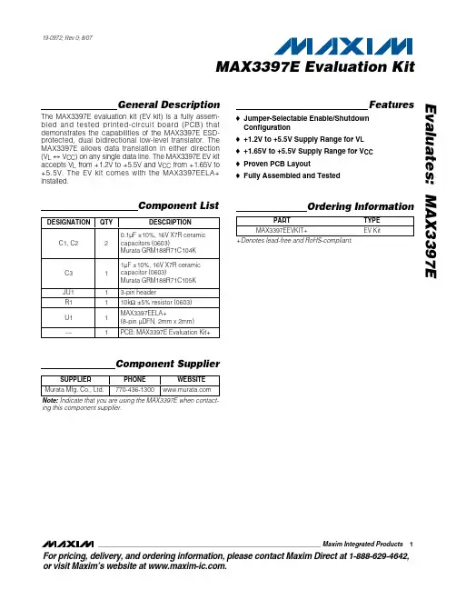
MAX4797ETT-T中文资料
- 格式:pdf
- 大小:281.06 KB
- 文档页数:9
General DescriptionThe MAX4795–MAX4798 family of switches feature inter-nal current limiting to prevent damage to host devicesdue to faulty load conditions. These analog switcheshave a low 0.2Ωon-resistance and operate from a 2.0Vto 4.5V input voltage range. They are available with guar-anteed 450mA and 500mA current limits, making themideal for SDIO and other load-switching applications.When the switch is on and a load is connected to theport, a guaranteed blanking time of 14ms ensures thetransient voltages settle down. If after this blanking time,the load current is greater than the current limit, theMAX4795 and MAX4797 switches are turned off andFLAGis issued to the microprocessor. The switch can beturned on again by cycling the power or the ON input. The MAX4796 and MAX4798 have an autoretry featurewhere the switch turns off and issues a FLAGto themicroprocessor after the blanking time and then contin-uously checks to see if the overload condition is pre-sent. The switch remains on after the overload conditiondisappears and FLAGdeasserts.The MAX4795–MAX4798 are available in tiny, space-saving, 5-pin SOT23 and 6-pin TDFN (3mm x 3mm)packages.ApplicationsSDIOPDAs and Palmtop DevicesCell PhonesGPS Systems
Hand-Held DevicesFeaturesoGuaranteed Current Limit: 450mA and 500mAoThermal-Shutdown Protection oReverse-Current Protectiono0.2ΩOn-Resistanceo14ms Guaranteed Blanking TimeoFLAGFunctionoAutoretry (MAX4796/MAX4798)o80µA Supply Currento6µA Latchoff Current(MAX4795/MAX4797)o0.01µA Shutdown Currento+2V to +4.5V Supply RangeoFast Current-Limit Response TimeoTiny SOT23 and TDFN PackagesoUL Certification Pending
MAX4795–MAX4798450mA/500mA Current-Limit Switches
________________________________________________________________Maxim Integrated Products
1Ordering Information+2.0V TO +4.5V
IN
OUTFLAG
GNDONµPTO SDIO PORTMAX4795MAX4796MAX4797MAX4798Typical Operating Circuit19-2944; Rev 0; 8/03
For pricing, delivery, and ordering information,please contact Maxim/Dallas Direct!at 1-888-629-4642, or visit Maxim’s website at www.maxim-ic.com.PARTTEMP RANGEPIN-PACKAGETOPMARKMAX4795EUK-T-40°C to +85°C5 SOT23-5AEDIMAX4795ETT*40°C to +85°C6 TDFN-EP**—MAX4796EUK-T-40°C to +85°C5 SOT23-5AEDJMAX4796ETT*-40°C to +85°C6 TDFN-EP**—MAX4797EUK-T-40°C to +85°C5 SOT23-5AEDKMAX4797ETT*-40°C to +85°C6 TDFN-EP**—MAX4798EUK-T-40°C to +85°C5 SOT23-5AEDLMAX4798ETT*-40°C to +85°C6 TDFN-EP**—
GND
FLAG15OUTINMAX4795MAX4796MAX4797MAX4798SOT23TOP VIEW
234ONOUTFLAG16ON5GNDINMAX4795MAX4796MAX4797MAX4798TDFN234N.C.Pin Configurations*Future product—contact factory for availability.**EP = Exposed pad.Selector Guide appears at end of data sheet.元器件交易网www.cecb2b.com
MAX4795–MAX4798450mA/500mA Current-Limit Switches
2_______________________________________________________________________________________ABSOLUTE MAXIMUM RATINGS
ELECTRICAL CHARACTERISTICS(VIN= +2.0V to +4.5V, TA= -40°C to +85°C, unless otherwise noted. Typical values are at VIN= 3.3V, TA= +25°C.) (Note 1)Stresses beyond those listed under “Absolute Maximum Ratings” may cause permanent damage to the device. These are stress ratings only, and functionaloperation of the device at these or any other conditions beyond those indicated in the operational sections of the specifications is not implied. Exposure toabsolute maximum rating conditions for extended periods may affect device reliability.
Note 1:All parts are 100% tested at +25°C. Electrical limits across the full temperature range are guaranteed by design and correlation.Note 2:Latch-off current does not include the current flowing into FLAG.Note 3:TDFN packages are guaranteed by design.Note 4:The on-time is defined as the time taken for the current through the switch to go from 0mA to full load. The off-time is defined asthe time taken for the current through the switch to go from full load to 0mA.Note 5:Retry time is typically 15 times the blanking time.IN, ON, FLAG, OUT to GND.....................................-0.3V to +6VOUT Short Circuit to GND.................................Internally LimitedContinuous Power Dissipation (TA= +70°C)5-Pin SOT23 (derate 7.1mW/°C above +70°C)............571mW6-Pin TDFN (derate 24.4mW/°C above +70°C).........1951mWOperating Temperature Range...........................-40°C to +85°CJunction Temperature......................................................+150°CStorage Temperature Range.............................-65°C to +150°CLead Temperature (soldering, 10s).................................+300°C
PARAMETERSYMBOLCONDITIONSMINTYPMAXUNITSOperating VoltageVIN2.04.5VQuiescent CurrentIQVON = VIN, IOUT = 0, switch onVIN = +3.3V80125µALatch-Off CurrentILATCHVON = VIN, after an overcurrentfault (MAX4795/MAX4797) (Note 2)VIN = +3.3V610µAShutdown CurrentISHDNVON = 0V0.031µAMAX4795/MAX4796, VIN = 3.3V, VOUT = GND450720Forward Current LimitMAX4797/MAX4798, VIN = 3.3V, VOUT = GND500800mAMAX4795/MAX4796720Reverse Current LimitMAX4797/MAX4798800mAON Input Leakage-1+1µAShutdown Forward LeakageVON = 0V, VOUT = 0V0.011µAShutdown Reverse LeakageVON = 0V, VIN = 2V, VOUT = 4.5V1µAMAX4795/MAX4796, ILOAD = 100mA0.20.4On-Resistance (Note 3)RONMAX4797/MAX4798, IL OA D = 100m A0.180.36ΩVIN = +2V to +3.6V1.4ON Input Logic High VoltageVIHVIN > 3.6V2VON Input Logic Low VoltageVIL0.5VFLAG Output Logic Low VoltageIS IN K = 1m A0.4VFLAG Output High LeakageCurrentVIN = V F LAG = VON = 4.5V1µAThermal Shutdown150°CThermal-Shutdown Hysteresis15°CDYNAMICTurn-On TimeV ON fr om l ow to hi g h; IOU T = 10m A, C L = 0.1µF ( N ote 4) 120µsTurn-Off TimeV ON fr om hi g h to l ow ; IOU T = 10m A, C L = 0.1µF ( N ote 4) 100nsBlanking TimetBLANKOvercurrent fault; Figures 2, 31460msShort-Circuit Current-LimitResponse TimeVON = VIN, short circuit applied to OUT5µsRetry TimetRETRYMAX4796/MAX4798, Figure 2 (Note 5)210900ms元器件交易网www.cecb2b.com