丰田 卡罗拉 1ZR-FE 发动机 维修手册 故障诊断手册2
- 格式:pdf
- 大小:14.56 MB
- 文档页数:46

卡罗拉发动机无法启动故障诊断与排除作者:李爱军来源:《中国科技纵横》2019年第02期摘要:本文主要介绍一辆2010生产的卡罗拉汽车,由于曲轴位置传感器线束1号针脚至ECM B31的122针脚信号线路断路,造成曲轴位置传感器无法向ECM提供曲轴位置信号,使发动机不能正常启动着车。
为了确定发动机的故障范围,在工作原理分析基础上,通过使用万用表、解码仪等工具进行相关基本检查和诊断,最终将故障排除。
关键词:发动机;曲轴位置传感器;信号线路;ECM中图分类号:U464 文献标识码:A 文章编号:1671-2064(2019)02-0089-02汽车发动机不能启动,会给人们带来交通麻烦,要做到快速准确的解决维修车辆,需要仔细研究汽车在出现故障的相关情况,这将有助于我们准确排除车辆故障。
1 故障现象一辆2010年生产的卡罗拉1.6GL版三厢轿车,搭载1ZR型发动机,里程表显示已经行驶了七万公里。
询问车主得知,该车就在2个月前发生撞车交通事故,发动机进行吊装维修和钣金维修。
但是现在打不着车,起动机运转正常,且无着车症兆。
2 工作原理分析2.1 发动机正常启动的条件发动机正常启动应具备的条件是针对汽油电子控制燃油喷射系统发动机而言,发动机要想正常启动具备以下条件:(1)要有可燃的混合气。
(2)要有足够的点火电压。
(3)有足够高的压缩压力。
2.2 点火系统工作原理发动机要正常启动,前提是点火系统必须正常。
点火系统经常出现的故障为单缸断火或多缸不点火,对于单缸断火,通常不会导致发动机不能启动,就是抖动比较严重。
如果全部缸不点火会使发动机无法启动。
而出现全部缸不点火的原因对于点火系统来说,主要存在于其控制电路部分。
点火系统电路工作原理如图1所示。
该车的点火系统是采用单缸独立点火系统。
各缸点火线圈电源是1号线+B由蓄电池经过保险丝A提供,搭铁为4号端子,各缸共用搭铁线。
2号线IGF信号为点火反馈信号,当点火成功后点火线圈会给一个信号给ECM,ECM接收信号后进行一下次点火。
丰田卡罗拉发动机停机系统故障诊断与排除作者:黄中景来源:《时代汽车》 2018年第5期摘要:基于大部分维修人员对汽车停机系统原理不理解或理解存在偏差,导致在对汽车发动机停机系统检修效率大大降低,甚至损坏零件,使得维修无法顺利进行,本文以田罗拉发动机停机系统故障引发发动机无法起动为例,对发动机停机系统故障的诊断和排除进行了深入的研究和探讨。
关键词:丰田卡罗拉;发动机停机系统;故障诊断与排除1故障现象一辆从某维修厂拖过来的丰田卡罗拉1.6GL AT轿车,搭载1ZR - FE发动机,行程12万公里,起动车辆时起动机不能运转,发动机无初始燃烧现象,故障指示灯显示正常。
2故障原因分析汽车发动机无法起动是汽车常见的故障之一,引起该故障的原因也非常多,发动机不能转动故障主要存在于两个方面: (1)起动机系统故障; (2)发动机停机系统故障。
据车主介绍,该车在某维修厂维修人员对起动电路做了检修并更换了起动机,但故障依然存在。
首先检查蓄电池电压、蓄电池电解液、发动机外接电路、机油、冷却液均正常。
将钥匙插入点火开点,汽车安全指示灯点每2S闪烁一次,点火开关打到ON时,发动机故障灯显示正常,起动发动机,起动机没有转动,正常情况,原车钥匙插入后安全指示灯长亮2S后熄灭。
根据检查和车主反映的情况,初步判断故障存在于发动机停机系统。
3丰田卡罗拉发动机停机系统的结构和工作原理3.1 丰田卡罗拉发动机机停机系统的组成丰田卡罗拉轿车上装置的是不带智能进入和启动系统。
该系统主要由带芯片的点火钥匙、应答器钥匙线圈/放大器、应答器钥匙ECU、未锁警告开关、ECM、安全指示灯等组成。
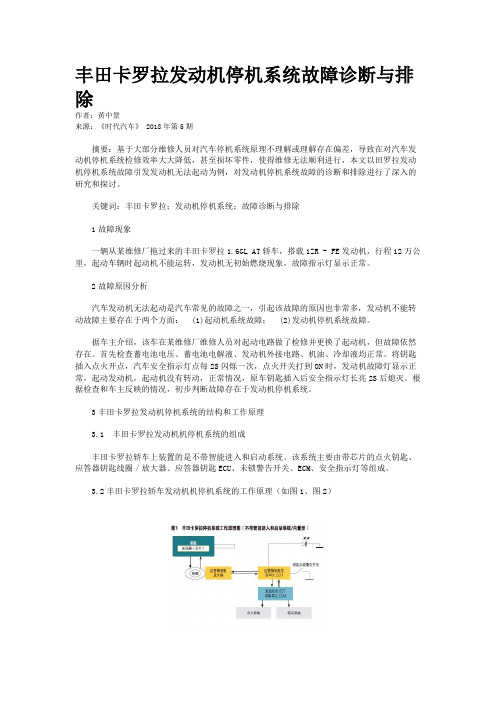
3.2丰田卡罗拉轿车发动机机停机系统的工作原理(如图1、图2)(1)经过注册的钥匙插入点火开关时,应答器钥匙ECU检测到钥匙未锁警告开关处于ON,ECU向应答器钥匙线圈提供电流并产生电波,钥匙柄内的应答器芯片接收该电波,然后输出钥匙ID代码信号,应答器钥匙线圈接收已经被应答器芯片输出钥匙放大器放大的信号,然后将信号发送到ECU。


SAE Technical Standards Board Rules provide that: “This report is published by SAE to advance the state of technical and engineering sciences. The use of this report is entirely voluntary, and its applicability and suitability for any particular use, including any patent infringement arising therefrom, is the sole responsibility of the user.”SAE reviews each technical report at least every five years at which time it may be reaffirmed, revised, or cancelled. SAE invites your written comments and suggestions.QUESTIONS REGARDING THIS DOCUMENT: (724) 772-8512 FAX: (724) 776-0243TO PLACE A DOCUMENT ORDER; (724) 776-4970 FAX: (724) 776-0790SAE WEB ADDRESS 1.Scope—This SAE Recommended Practice defines the information contained in the header and data fields ofnon-diagnostic messages for automotive serial communications based on SAE J1850 Class B networks. This document describes and specifies the header fields, data fields, field sizes, scaling, representations, and data positions used within messages.The general structure of a SAE J1850 message frame without in-frame response is shown in Figure 1. The structure of a SAE J1850 message with in-frame response is shown in Figure 2. Figures 1 and 2 also show the scope of frame fields defined by this document for non-diagnostic messages. Refer to SAE J1979 for specifications of emissions related diagnostic message header and data fields. Refer to SAE J2190 for the definition of other diagnostic data fields. The description of the network interface hardware, basic protocol definition, the electrical specifications, and the CRC byte are given in SAE J1850.FIGURE 1—SCOPE OF SAE J2178 FOR A SAE J1850 FRAME WITHOUT IN-FRAME RESPONSE (IFR)FIGURE 2—SCOPE OF SAE J2178 FOR A SAE J1850 FRAME WITH IN-FRAME RESPONSE (IFR)SAE J1850 defines two and only two formats of message headers. They are the Single Byte header format and the Consolidated header format. The Consolidated header format has two forms, a Single Byte form anda three byte form. This document covers all of these formats and forms to identify the contents of messageswhich could be sent on a SAE J1850 network.This document consists of four parts, each published separately.SAE J2178-1 (Titled: Detailed Header Formats and Physical Address Assignments) describes the two allowed forms of message header formats, Single Byte and Consolidated. It also contains the physical node address range assignments for the typical sub-systems of an automobile.SAE J2178-2 (Titled: Data Parameter Definitions) defines the standard parametric data which may be exchanged on SAE J1850 (Class B) networks. The parameter scaling, ranges, and transfer functions are specified. Messages which refer to these parametric definitions shall always adhere to these parametric definitions. It is intended that at least one of the definitions for each parameter in this part matches the SAE J1979 definition.SAE J2178-3 (Titled: Frame IDs for Single Byte Forms of Headers) defines the message assignments for the single byte header format and the one byte form of the consolidated header format.SAE J2178-4 (Titled: Message Definition for Three Byte Headers) defines the message assignments for the three byte form of the consolidated header format.2.References2.1Applicable Publications—The following publications form a part of this specification to the extent specifiedherein. Unless otherwise specified, the latest issue of SAE publications shall apply.2.1.1SAE P UBLICATIONS—Available from SAE, 400 Commonwealth Drive, Warrendale, PA 15096-0001.SAE J1213-1—Glossary of Vehicle Networks for Multiplex and Data CommunicationSAE J1850—Class B Data Communication Networks InterfaceSAE J1930—Electrical/Electronic Systems Diagnostic Terms, Definitions, Abbreviations, and AcronymsSAE J1979—E/E Diagnostic Test ModesSAE J2190—Enhanced E/E Diagnostic Test Modes2.1.2ANSI/IEEE P UBLICATION—Available from ANSI, 11 West 42nd Street, New York, NY 10036-8002.ANSI/IEEE 754-1985—IEEE Standard for Binary Floating-Point Arithmetic3.Definitions3.1Data [Data Field]—Data and data field are used interchangeably in this document and they both refer to afield within a frame that may include bytes with parameters pertaining to the message and/or secondary ID and/or extended addresses and/or test modes which further defines a particular message content being exchanged over the network.3.2Extended Address—The extended address is a means to allow a message to be addressed to ageographical location (such as geographic) or zone of the vehicle, independent of any node's physical address.3.3Frame—A frame is one complete transmission of information which may or may not include an In-FrameResponse. The frame is enclosed by the start of frame and end of frame symbols. For Class B networks, each frame contains one and only one message (see "message" definition below).3.4Frame ID—The Frame ID is the header byte for the Single Byte Header format and the one byte form of theconsolidated header format. The definition of the frame ID is found in SAE J2178-3. This header byte defines the target and source and content of the frame.3.5Functional Addressing—Functional addressing allows a message to be addressed or sent to one or morenodes on the network interested in that function. Functional addressing is intended for messages that may be of interest to more than a single node. For example, an exterior lamp "off" message could be sent to all nodes controlling the vehicle exterior lamps by using a functional address. The functional address consists of a primary ID and may include a secondary ID and may also include an extended address.3.6Header [Header Field]—The header (or header field, used interchangeably) is a one or three byte field withina frame which contains information about the message priority, message source and target addressing,message type, and in-frame response type.3.7In-Frame Response (IFR) Type—The IFR type identifies the form of the in-frame response which is expectedwithin that message.3.8Load—The load command indicates the operation of directly replacing the current/existing value of aparameter with the parameter value(s) contained in the message.3.9Message—A message consists of all of the bytes of a frame excluding the delimiter symbols (SOF, EOD,EOF, NB).3.10Modify—The modify command indicates the operation of using the message data parameter value to change(e.g., increment, decrement, or toggle) the current/existing value.3.11Parameter—A parameter is the variable quantity included in some messages. The parameter value, scaling,offset, units, transfer function, etc., are unique to each particular message. (The assigned parameters are contained herein.)3.12Physical Addressing—Physical addressing allows a message to be addressed to a specific node or to allnodes or to a non-existent, null node. The information in this message is of relevance only to a particular node, so the other nodes on the bus should ignore the message, except for the case of the "all nodes" address.3.13Primary ID—The primary ID identifies the target for this functional message. This is the primary discriminatorused to group functions into main categories.3.14Priority—The priority describes the rank order and precedence of a message. Based upon the SAE J1850,Class B arbitration process, the message with the highest priority will win arbitration.3.15Report—A report indicates the transmission of parametric data values, based on: a change of state; a changeof value; on a periodic rate basis; or as a response to a specific request.3.16Request—A request is a command to, or a query for data, or action from another node on the network.3.17Response Data—The response data is the information from a node on the network in response to a requestfrom another node on the network. This may be an in-frame response or a report type of message.3.18Secondary ID—The secondary ID (along with the primary ID or Frame ID) identifies the functional target nodefor a message. The purpose of the secondary ID field within the frame is to further define the function or action being identified by the primary ID.4.Abbreviations and AcronymsA/C - Air ConditioningASC - ASCII Encoded SLOTBCD - Binary Coded Decimal (BCD) SLOTBMM - Bit Mapped with Mask SLOTBMP - Bit Mapped without Mask SLOTCRC - Cyclic Redundancy CheckCS - ChecksumDTC - Diagnostic Trouble CodeEOD - End of DataEOF - End of FrameERR - Error DetectionEV-ETS - Electric Vehicle Energy Transfer SystemEVSE - Electric Vehicle Supply EquipmentHVAC - Heating, Ventilation, Air ConditioningID - IdentifierIFR - In-Frame ResponseLSB - Least Significant Bit/ByteMSB - Most Significant Bit/ByteNB - Normalization BitPID - Parameter IDentification (number, NOT the primary ID, (See Section 7)PKT - Multiple Parameter Packet SLOTPRN - Parameter Reference NumberSED - State Encoded SLOTSFP - Signed Floating Point (Scientific Notation) SLOTSLOT - Scaling, Limit, Offset, and Transfer Function (See Section 8)SNM - 2's Complement Signed Numeric SLOTSOF - Start of FrameUNM - Unsigned Numeric SLOTVIN - Vehicle Identification Number5.General Information5.1Part 1 Overview—The messages defined by this four part document are specified for networks using singlebyte headers or consolidated one and three byte headers as specified in SAE J1850. Sections 6 and 7 of SAE J2178-1 provide the system architecture for the different possible headers used in Class B network communication (see Appendix A for supporting discussion). Section 8 of SAE J2178-1 defines the data fields used by the different header byte formats. Section 9 of SAE J2178-1 defines the physical address assignments.Figure 3 shows an overview of this part (Part 1) which encompasses the different possible messages and their component parts.FIGURE 3—PART 1 OVERVIEWSAE J1850 defines two and only two formats of message headers. They are the Single Byte header format and the Consolidated header format. The Consolidated header format has two forms, identified by the value of the H Bit. The two forms are: a one byte form and a three byte form. The information in the header field for both formats contains target, source, priority and message type information, while the data field contains additional addressing and/or parametric information and/or diagnostic test modes. This information is explicitly defined in some headers and implicitly defined in others. Messages defined by this document (Parts 1, 2, 3, and 4) are classified generally into two types:a.Requests, that is, commands (load or modify) or queries for data, andb.Responses, that is, reports or acknowledgments.When a node generates a request, the target nodes which are responsible for the requested data or function must respond by reporting the requested information or by performing the requested function. For responses (that is, reports or acknowledgments), data information that a node responds with may have been previously requested by another node, or reported by the node when the desired information has changed, or reported by the node on a periodic basis.SAE J2178-1 describes the overall structure of messages. In total, parts 1, 2, 3, and 4:a.Fully define SAE (automotive industry) standard messages.b.Reserve messages for future SAE standardization.c.Reserve messages for manufacturers to allocate, which are typically unique or proprietary to thatmanufacturer.In order to comply with this document, implementations need to use the defined messages on SAE J1850 networks in the exact way that they are defined here. However, there are a large number of message codes that are reserved for each manufacturer to independently allocate.5.2In-Frame Response Field Formats—The total number of bytes in the frame (not including frame delimiters) is12, including the header (1 or 3 depending on header type), data (both in the message and IFR), and single byte CRC. Therefore, the total number of message and IFR data bytes can be 10 if using a single byte header or the one byte form of the consolidated header, or 8 bytes if using the three byte form of the consolidated header.5.2.1I N-F RAME R ESPONSE T YPE 0—The in-frame response type 0 is used to indicate the form without any in-frameresponse.5.2.2I N-F RAME R ESPONSE T YPE 1—The in-frame response type 1 is a single byte response from a singleresponder. The response byte shall be the physical address of a receiver of the message. No CRC byte is included for this response data.5.2.3I N-F RAME R ESPONSE T YPE 2—The in-frame response type 2 is a single byte response from multipleresponders. The response byte(s) shall be the physical address of the receiver(s) of the message. No CRC byte is included for the response data.5.2.4I N-F RAME R ESPONSE T YPE 3—The in-frame response type 3 is a multiple byte response from a singleresponder. The response bytes shall be data (generally not its address) from a single responder. The second CRC byte is included for the data integrity of the response data. The actual in-frame response data shall be one byte in length, as a minimum.Figure 4 illustrates the four IFR types.FIGURE 4—TYPES OF IN-FRAME RESPONSE6.Single Byte Header Messages and Format—For single byte header messages, the entire byte is used todefine the message identifier (ID) as shown in Figure 5. This allows up to 256 unique message identifiers to bedefined. Standard message identifiers that utilize this header format are found in SAE J2178-3.All single byte header messages utilize one of the four in-frame response (IFR) types Figure 4.7.Consolidated Header Messages and Format—The consolidated header format includes both a one byte form and a three byte form.7.1One Byte Form of the Consolidated Header Format—The one byte form utilizes 7 bits for the message identifier thereby allowing up to 128 distinct Ids. The H bit (bit 4) is always a logic "1" signifying the one byte form of the consolidated header. Figure 6 illustrates this message header form. Standard message identifiers that utilize this header form are defined in SAE J2178-3.FIGURE 6—ONE BYTE FORM OF CONSOLIDATED HEADERIn order to accommodate a one byte header form and a three byte header form on the same network, the header type bit (H bit) in the first byte of the message has been defined to indicate the header form. This bit is defined in Table 1.All one byte header form messages of the consolidated header format utilize one of the four in-frame response (IFR) types (see Figure 4).7.2Three Byte Form of the Consolidated Header Format—This header form utilizes the first three bytes of the message. The H bit (bit 4) is always a logic "0" signifying the three byte form. Standard message identifiers that utilize this header form are defined in SAE J2178-4. The remaining seven bits of the first byte contain information about priority (PPP) and message type (KYZZ). The second byte contains the target address information. The target can be either functionally addressed or physically addressed. The third byte contains the physical address of the source of the message. Arbitration is always resolved by the end of the third byte,since the source address must be unique. Figures 7 and 8 illustrate this message header form.FIGURE 7—THREE BYTE FORM OF CONSOLIDATED HEADERTABLE 1—H BIT DEFINITIONH Bit Header Byte Form 0Three Byte Form 1One Byte FormFIGURE 8—FIRST BYTE OF THREE BYTE FORM OF CONSOLIDATED HEADERAll three byte header messages utilize one of the four in-frame response (IFR) types (see Figure 4, 4).7.2.1P RIORITY /T YPE -B YTE 1—The priority/type byte contains information about priority, in-frame response,addressing type, and type modifier. Each of the field definitions is described in the following paragraphs.7.2.1.1Priority (PPP Bits)—The priority field is three bits in length and immediately proceeds the header type (H)bit. The priority bit definition is shown in Table 2. The priority bit assignments for a particular message are manufacturer specific and are not assigned by SAE J2178.7.2.1.2Header Type (H Bit)—In order to accommodate a one byte header form and a three byte header form on the same network, the header type bit (H bit) in the first byte of the message has been defined to indicate the header form. This bit is defined in Table 3.TABLE 2—PRIORITY FIELD ASSIGNMENTSPPP Bits Priority Level 0000Highest0011.0102.0113.1004.1015.1106.1117LowestTABLE 3—H BIT DEFINITIONH Bit Head Byte Form 0Three Byte Form 1One Byte Form7.2.1.3In-Frame Response (K Bit)—The necessity for in-frame response is encoded into a single bit in the priority/type byte. This bit definition is shown in Table 4.TABLE 4—"K" BIT ASSIGNMENTSK Bit In-Frame Response0Required1Not Allowed7.2.1.4Addressing Type (Y Bit)—Message addressing is encoded with a single bit in the priority/type byte. Thisbit definition is shown in Table 5.TABLE 5—"Y" BIT ASSIGNMENTSY Bit Addressing Type0Functional1Physical7.2.1.5Type Modifier (ZZ Bits)—The type modifier is encoded as a two bit field (ZZ) and is used in conjunctionwith the in-frame response bit (K) and the address type bit (Y) to define sixteen message types,see Table 6.TABLE 6—THE SIXTEEN MESSAGE TYPESMsg Response Addressing IFRType KYZZ(K bit)(Y bit)Type Message Type (Name)00000Required Functional2Function10001Required Functional1Broadcast20010Required Functional2Function Query30011Required Functional3Function Read40100Required Physical1Node-to-Node50101Required Physical—Reserved - MFG60110Required Physical—Reserved - SAE70111Required Physical—Reserved - MFG81000Not Allowed Functional0Function Command/Status91001Not Allowed Functional0Function Request/Query101010Not Allowed Functional0Function Ext. Command/Status111011Not Allowed Functional0Function Ext. Request/Query121100Not Allowed Physical0Node-to-Node131101Not Allowed Physical0Reserved - MFG141110Not Allowed Physical0Acknowledgement151111Not Allowed Physical0Reserved - MFGNOTE 1—Functional addresses for the three byte form of the consolidated header are defined in SAE J2178-4.Physical address ranges are defined in Section 7 of this part.NOTE 2—Message types 8 and 9 use functional data format #2 only; message types 10 and 11 use functional dataformat #3 only.NOTE 3—Reserved - SAE indicates reserved for future SAE Committee action. Reserved - MFG indicates thatmanufacturers are allowed to allocate these definitions without requiring any commonality between motorvehicle manufacturers.7.2.2TARGET A DDRESS -B YTE 2—The second byte of the three byte form of the consolidated header format contains either a functional or physical target address. The physical address assignments are found in Section 8 of this part, while functional message address assignments are in SAE J2178-4.Functional addresses are assigned in pairs where the only difference between the ID values is the least significant bit (W bit). Figure 9 illustrates the functional target address with W bit.FIGURE 9—FUNCTIONAL TARGET ADDRESSThe W bit is logic "0" to signify a Command target and logic "1" to signify a Status target. This bit is defined in Table 7.7.2.3S OURCE A DDRESS -B YTE 3—The third byte of the three byte format of the consolidated header format is the physical address of the source of the message. Physical address assignments are found in Section 9.These physical address assignments shall be unique for each node of a network.8.Data Field Formats—In both message header formats, single byte and consolidated, the data field can usually be encoded in the same way. This section briefly describes the different ways that information can be formatted in the data field. The data field immediately follows the header field. The number of bytes in this field will vary, based upon the content of the header field. The maximum data field length is limited by the requirements of SAE J1850. Because of differences in functionally and physically addressed messages or with in-frame response data, these cases are defined separately.8.1Functional Data Field Formats8.1.1F UNCTIONAL D ATA F IELD F ORMAT 0—One of the functional data field formats is, in fact, no additional bytes of data (an empty data field). The message consists of the header, error checking byte, and in-frame response bytes. This is the format used for functional message types 2 and 3. Because the data field does not actually exist but to allow referencing in other parts of this document, it has been identified as the functional data field format 0.8.1.2F UNCTIONAL D ATA F IELD F ORMAT 1—In the simplest case including data (format 1), the data field contains only parametric data. The first byte of the data field in this case contains the most significant byte of data.The data field must contain one byte as a minimum. Figure 10 illustrates this message format. This data field format may be used for message types 0 and 1 only.FIGURE 10—FUNCTIONAL DATA FIELD FORMAT 1TABLE 7—W BIT DEFINITIONW Bit Functional Target Address Type0Command 1Status8.1.3F UNCTIONAL D ATA F IELD F ORMAT 2—In a data field format 2 message, the data field contains a byte which isused to further define the target function being addressed. In this format type, the data field would appear as shown in Figure 11. This data format may be used for message types 0, 1, 8 and 9.FIGURE 11—FUNCTIONAL DATA FIELD FORMAT 2The secondary address byte consists of a parameter/quantity bit (Q bit) in which binary data (such as, on/off or yes/no) can be encoded. There is a listing of the possible uses for this bit in SAE J2178-4. The control bit(C bit) is used to distinguish between an immediate load of data or a modify of the current data for commandmessages, or to distinguish between request/report and query message operations. The remaining six bits specify a secondary ID address. The order of these bits within the secondary address byte is shown in Figure 12.FIGURE 12—SECONDARY ADDRESS BYTE FORMATIn many cases, a single data bit (i.e., the Q bit) is not adequate to define the data parameter being sent. In this case, the identifier field is followed by an additional data field as illustrated in Figure 13. The combination of the primary and secondary addresses defines whether additional data is used by that message.FIGURE 13—FUNCTIONAL DATA FIELD FORMAT 2, WITH DATA BYTES8.1.3.1The Parameter/Quantity Bit (Q bit)—The Q bit is used to represent single, binary values. Refer to SAEJ2178-4 for a list of valid uses for the Q bit.8.1.3.2The Control Bit (C bit)—The C bit represents an action or operation to be taken with the associated datavalues. Table 8 shows how the W and C bits are used in conjunction with the eight functionally addressed messages types (0-3, and 8-11) to define a particular message operation.Modify messages adjust (e.g., increment/decrement) or toggle the state of existing data. Load messages replace current or existing data. Request messages "ask" for existing status or command data. Report messages "tell" existing status. Query messages "ask" for the receivers of a message without asking for the associated data.8.1.3.3The Secondary ID—The secondary identification field is used to further identify the particular function or operation being addressed by this message. It is used to distinguish a function when the primary ID is not sufficient, or to define a specific operation to be performed by the function addressed by the primary ID.These secondary identification addresses are assigned in SAE J2178-3 and SAE J2178-4.8.1.4F UNCTIONAL D ATA F IELD F ORMAT 3—In a data field format 3 message, depending on the particular primary and secondary ID, the data field may also contain an extended address byte which defines the geographical location within the vehicle of the target function being addressed. This data field format may be used for message types 0 and 1 and must be used for message types 10 and 11. In this data field type, the data field appears as shown in Figure 14.TABLE 8—MESSAGE OPERATIONSMsg Type KYZZ W C Message TypeMessage Operation000000FunctionLoad Command 01Modify Command 10Report Status 11MFG Specific 1000100Broadcast Load Command 01Modify Command 10Report Status 11MFG Specific 200100n/a Function Query Command Query 1n/a Status Query 30011n/a n/a Function Read Not Applicable 8100000Function Command/StatusLoad Command 01Modify Command 10Report Status 11MFG Specific 9100100Function Request/Query Status Request 01Report Acknowledge 10Command Request 11Function Query10101000Function Ext. Command/StatusLoad Command Extended 01Modify Command Extended 10Report Status Extended 11MFG Specific11101100Function Ext. Request/QueryStatus Request Extended 01Report Acknowledge Extended 10Command Request Extended 11Function Query ExtendedFIGURE 14—FUNCTIONAL DATA FIELD FORMAT 3The extended address byte is used to determine where, geographically on a vehicle, a particular function is located. The exact definition of the extended address values can be found in 8.3. The secondary address in Figure 14 is used as defined in 8.1.3.As in the other data field formats, a parameter data field may also be needed and in this case it is then appended to the end of the other identifiers. This format is shown in Figure 15.FIGURE 15—FUNCTIONAL DATA FIELD FORMAT 3, WITH DATA BYTES8.1.5F UNCTIONAL D ATA F IELD F ORMAT 4—In this data field format message, the data field contains a byte whichdefines the diagnostic test mode of the target function being addressed. In this type, the data field would appear as shown in Figure 16. This data format may be used for message types 0, 1, 8 and 9.FIGURE 16—FUNCTIONAL DATA FIELD FORMAT 4The test mode byte is used to determine which diagnostic function is involved. It may be followed by parameter data fields. In this case, the additional data bytes follow the test mode byte. This format is shown in Figure 17. This is the format for functionally addressed diagnostic messages such as those found in SAE J1979.FIGURE 17—FUNCTIONAL DATA FIELD FORMAT 4, WITH DATA BYTES8.2Physical Data Field Formats—The previous section (8.1) defined the data field formats for functionallyaddressed messages. This section (8.2) defines the data field formats for physically addressed messages. 8.2.1P HYSICAL D ATA F IELD F ORMAT 0—One of the physical data field formats is, in fact, no additional bytes of data(an empty data field). The message consists of the header, error checking byte, and may be with or without in-frame response bytes. This is the format used for the acknowledgement message type. This message type simply confirms to another node that the message has been received correctly. Because this data field does not actually exist but to allow referencing in other parts of this document, it has been identified as the physical data field format 0.8.2.2P HYSICAL D ATA F IELD F ORMAT 1—Physical data field format 1 is generally associated with the node-to-nodemessage types. This message type is the one utilized for enhanced E/E diagnostic test modes (see SAE J2190). This format assumes the three byte form of the consolidated header format. The single byte format and the one byte form of the consolidated header format are covered in physical data field format 2 (see8.2.3). Many of the specific diagnostic messages are defined in SAE J2190. This description of the format isconsistent with SAE J2190 but expands the definition to allow the format to be used in other messages as well. In particular, the manufacturer specific applications of this node-to-node message are expected to follow this format. The basic format is similar to the functional data field format 4. The format is shown in Figure 18.FIGURE 18—PHYSICAL DATA FIELD FORMAT 1The format will often include data bytes as shown in Figure 19. The contents of the test mode byte indicate if additional data bytes are used.FIGURE 19—PHYSICAL DATA FIELD FORMAT 1, WITH DATA BYTES The physical test mode byte details are shown SAE J2190.8.2.3P HYSICAL D ATA F IELD F ORMAT 2—In order to maximize commonality between the different header byteformats, the physical data field format 2 is essentially the same as physical data field format 1 with the insertion of the physical target address byte ahead of the physical test mode byte. This allows the single byte header format and the one byte form of the consolidated header format to operate consistently with the three byte header form. The format is shown in Figures 20 and 21 for the two cases, without and with additional data bytes, respectively.FIGURE 20—PHYSICAL DATA FIELD FORMAT 2FIGURE 21—PHYSICAL DATA FIELD FORMAT 2, WITH DATA BYTES8.3Extended Addressing—Extended addressing defines an extended (geographical) location in the vehicle.The upper two bits of the extended address (RR) are used to allow up to four different types of extended addressing. Table 9 shows these bit assignments.TABLE 9—EXTENDED ADDRESS TYPESRR Type00Geographical Addressing01Reserved - SAE10Reserved - MFG11Reserved - MFG。

基于丰田卡罗拉车型的VVT-i系统构造及故障检修摘要:丰田卡罗拉汽车市场保有量较大,其搭载了丰田1ZR-FE 双VVT-i 发动机,此技术能够根据不同路况适时改变发动机气门的开闭时刻,提高汽车发动机动力性、经济性但却能降低污染物的排放。
本文重点介绍丰田卡罗拉VVT-i 系统的结构、工作原理及故障检修,为汽车教育工作者及维修人员提供技术支持。
关键词:VVT-i系统构造故障检修科技的不断进步,发动机的构造已非常成熟,若发动机在原有基础上的改进与研发则牵动着发动机的发展。
配气机构作为发动机两大机构五大系统中的一部分,它的地位显得非常重要。
VVT-i系统是丰田公司典型的可变气门正时。
ECU 可根据发动机传感器的不同的信号发出控制指令,通过调节油路中的油压来改变正时,改变扭矩,从而及提高发动机动力及燃油经济性,进一步降低污染物的排放。
1.VVT- i的结构VVT—i系统和发动机其他电控系统类似,主要有传感器、ECU、执行器三部分所组成。
其中传感器为发动机上常见的基础传感器,执行器主要由控制器和凸轮轴正时机油控制阀。
1.1 VVT-i 控制器VVT-i 控制器是该系统的核心,主要由控制器外壳、叶轮、锁销等组成。
叶片与凸轮轴是固定的,而外壳与叶片是可以相对活动的。
控制器内的4 个叶片,将壳体分成提前室和滞后室。
控制阀能控制提前室和延迟室的机油压力,推动叶片相对壳体转动,从而改变配气相位。
发动机停止时,机油没有压力,进气侧凸轮轴被锁销固定在最延迟端。
发动机起动后,机油产生压力,克服弹簧的作用推动锁销复位使叶片转动。
1.2 凸轮轴正时机油控制阀凸轮轴机油控制阀是用来控制油压的,发动机缸盖上各装有进气侧和排气侧凸轮轴正时机油控制阀,主要有柱塞、线圈等组成。
其根据发动机ECU 的占空比来控制滑阀,从而来改变油道压力。
通过油压来控制VVT-i 控制器的提前侧或延迟侧。
2. VVT-i 系统工作原理当该系统工作时,ECU根据发动机上的基础传感器,例如空气流量计、节气门位置传感器及曲轴位置传感器等传来的信号进行收集及分析,然后发出对叶轮正时的控制指令,最后执行器电磁阀根据ECU的控制信号来推动滑阀动作。

丰田卡罗拉点火系统的故障诊断与排除前言:现代汽车产业和技术进入高速发展时期,汽车在使用过程产生的故障往往是很复杂的,有的是必然故障也有偶然的故障,有的故障是人为的故障比如是维修技术人员本身造成的,有的故障是意外产生比如是车泡水产生的故障,所以对一线维修技术人员的要求就要更高的了,才能满足汽车服务需要。
不仅要有扎实汽车专业知识,还要有较为清淅的分析思路和综合诊断故障的能力。
一、故障现象2014年11月份接了一辆2011年生产的丰田卡罗拉,该车是1.6L 排量的自动档轿车(右图),由于当地洪水爆发,把该车淹了,车主将该车拖到厂修理。
修理前把车清理干净,把线束拆下来冲洗干净,晒干,电脑板、感应器等也清洁干净,火花塞也全套换掉。
油箱、油路、缸内等入了水的地方都清理好。
启动汽车着车后,刚开始时,怠速稳定,加速也良好,但着了几分钟后发动机就自动熄火,于是马上着车,又能打着,一切又都正常。
但过几分钟后又出现故障,后来反复试多几次就发动不起来了,要等过几分钟再起动才能打着火,但发动机还是会自动熄火。
二、故障原因分析接车后进行分析:因为该车被水淹过,故障的原因是比较复杂,油箱里面进了大半箱水,所以第一考虑到发动机自动熄火的原因可能是燃油泵的问题;第二是线束的插座水淹后清理不够干净、生锈导致接触不良或搭铁不良;第三是点火线圈短路或断路,造成有时无高压跳火;第四是电脑里面有短路或断路;第五是发动机曲轴位置传感器和凸轮轴位置传感有故障,无法给信号到电脑,使电脑不能判断点火和喷油的正常时间。
三、故障的诊断与排除1、该车由于仪表给水淹坏了,且当时没有新的仪表换上,无法看到发动机的故障灯是否正常,所以不能直接读故障码。
用故障诊断仪连接诊断接口又因为诊断接口问题不能进入电脑系统。
读不到故障码,也就无法读出发动机的数据流。
所以只能根据自己修车积累的知识、经验来判断和分析故障的原因,检查故障出现的部位。
首先要检查的是汽油泵的油压是否正常,把汽油压力表安装到进油管上,启动发动机,怠速时,看到油压表的指针读数是280kpa,标准是300--350kpa,急加速时,油压表读数为320kpa,标准是300--350kpa ,且油压表指针在怠速和加速时都很稳定,不会上下来回的波动。
毕业设计(论文)设计(论文)题目:丰田卡罗拉发动机电控系统故障诊断方法学院名称:机械工程学院专业:汽车服务工程班级:汽车132班姓名:陈丽学号: 134******** 指导教师:钱岳明职称:讲师定稿日期:2017 年04月01日诚信承诺我谨在此承诺:本人所写的毕业论文《丰田卡罗拉发动机电控系统故障诊断方法》均系本人独立完成,没有抄袭行为,凡涉及其他作者的观点和材料,均作了注释,若有不实,后果由本人承担。
承诺人(签名):2017 年 04 月 01 日摘要在现今社会中,汽车已经发展为一种技术成熟,机电液合一的物品。
在这其中,发电机的电子控制不断升级,已经成为推动汽车行业向前发展的巨大推动力。
[7]这是因为发动机电子控制程序,是现代汽车正常运作的核心程序,是掌握正常驱动的主要因素,我们常常从发动机角度评判一辆车的性能高低,安全度高低,废气排量情况以及消耗油量情况,还以此来判断汽车是否能使乘客和驾驶员乘坐或驾驶时更加舒服自在[1]。
本文以丰田卡罗拉发动机电控系统为例,通过查阅相关文献与资料,了解丰田卡罗拉发动机的基本组成与原理,然后将部分常见的故障检查途径与专用设备判断综合起来考虑,共同用于探究卡罗拉发动机电控系统故障频发的现象,比如发动机抖动,怠速抖动,排气时尾气冒黑烟等进行诊断分析,总结出一个对于丰田卡罗拉发动机电控系统来说最为简易,方便的诊断方法。
本文主要是分析卡罗拉发动机电控系统发动机抖动,怠速抖动和排气冒黑烟等故障现象,深入探究发生的缘由并且研究诊断途径。
关键词:发动机;丰田卡罗拉;电控系统;故障;诊断ⅠABSTRACTAt present, Hyundai Motor has become a mechanical, electrical and hydraulic integration of high-tech, in which the engine electronic control technology has matured, as a high-tech carrier features more and more obvious. Automotive engine electronic control system as the core component of the car, equivalent to the heart of the car, the normal operation of the car to go to the need to maintain the automotive electronic control system, so for each car, the various parts of the car are electronic control system Command, and its performance directly affect the reliability, safety, power, economy, emissions purification and comfort, but compared with the carburetor-type engine, electronic control engine is relatively more complex, electronic control system failure and more With abstract, to bring a certain degree of difficulty in fault diagnosis, so people in the maintenance of electronic control engine, often unable to start. In fact, as long as the proper way, the maintenance of electronic control engine is not a problem.In this paper, Toyota Corolla engine electronic control system, for example, by consulting the relevant literature and information to understand the basic composition and principle of the Toyota Corolla engine, through fault detection methods and the use of automotive fault diagnostic apparatus, multimeter and other tools on the Toyota Corolla engine electronic control system Fault analysis, diagnosis and troubleshooting, and Toyota Corolla engine electronic control system failure to find the appropriate diagnostic method. The failure phenomenon, fault cause and fault diagnosis method of engine missing cylinder fault, idle speed fault and exhaust abnormal fault of Toyota Corolla engine electronic control system are studied emphatically.Key Words:Engine;Toyota Corolla;electric control system;fault;diagnosis目录1 引言 (1)2 研究背景 (2)3 丰田卡罗拉发动机电控系统 (3)3.1 丰田卡罗拉发动机电控系统基本组成 (3)3.2 丰田卡罗拉发动机电控系统工作原理 (3)4 丰田卡罗拉发动机电控系统的故障诊断方法 (5)4.1 人工诊断法 (5)4.1.1 故障征兆模拟试验方法 (6)4.1.2 故障征兆表诊断法 (6)4.2 专用测试仪器诊断方法 (8)4.2.1 电脑故障检测仪诊断方法 (8)4.2.2 示波器检测方法 (8)4.2.3 发动机尾气分析仪诊断方法 (9)4.3利用随车故障自诊断系统诊断 (10)5 丰田卡罗拉发动机电控系统故障诊断案例分析 (13)5.1 丰田卡罗拉发动机抖动故障 (13)5.2 丰田卡罗拉发动机怠速抖动故障 (15)5.3 丰田卡罗拉发动机排气冒黑烟故障 (17)结论 (19)致谢 (20)参考文献 (21)\1 引言人们对现代汽车的安全性、牢靠性、舒适性以及环保等方面的要求更为严格,这也使得电控系统在汽车的应用越来越普遍。
丰田卡罗拉的维修保养手册1、卡罗拉手动挡汽车踩离合器时易发出声响:原因是离合器踏板轴套缺油,可以与经销商联系,在轴套上加油。
2、后排车门从内侧有时无法打开:原因是儿童保护锁关闭,打开即可。
3、客户实际使用油耗与厂家提供的理论油耗有差别:原因是厂家提供理论油耗值是汽车在平坦路面匀速行驶时的耗油值,而用户实际驾驶时制动、转弯、承载人数等因素不同,造成了实际耗油量也有所差别。
一般情况下制动一次耗油量可行驶2—3公里。
车上承载重量增加50公斤,每公里多耗油0.5公升。
等人3分钟以上耗油明显增加,建议熄火等候。
4、汽油滤芯堵塞、喷油嘴积炭过多:原因是加注燃油纯净度低,污染节气门,使得汽油滤芯堵塞、喷油嘴积炭过多。
建议用户到正规加油站加油,并加注出厂时规定标号的燃油,一般情况下,加注95#以上燃油。
保养手册1、清洗车漆表面清洁和保护车辆内饰外饰的时候,请您注意:请勿使用有机清洁剂(如苯或汽油)。
2、清洗风挡玻璃从风挡玻璃处提起刮水器臂时,应先向上拉起驾驶员侧刮水器臂。
再以同样方式拉起乘员侧刮水器臂。
将刮水器臂恢复至其初始位置时,首先从乘员侧进行操作。
3、清洗车灯表面清洗时应小心,请勿使用有机清洗剂或硬刷进行清洗。
否则可能损坏车灯表面。
请勿在车灯表面打蜡,车蜡可能会损伤车灯罩。
4、清洗车窗内侧清洁玻璃内侧不要用玻璃清洁剂,因为其会导致后车窗除雾器电热丝或天线损坏。
应将布用温水浸湿,沿着与电热丝或天线平行的方向轻轻擦拭。
清洗内饰使用真空吸尘器清除污物和灰尘,将布用温水浸湿后,擦洗脏污的表面。
特别注意为了延长车辆的寿命,在新车磨合期间,请您注意:在最初300km(公里)内,请避免紧急停车。
在最初1000km(公里)内,避免以极高车速驾驶,避免突然加速,请勿持续在低速挡行驶。
挂档困难:离合器故障排除方法一、故障现象: 发动机怠速运转时,离合器踏板虽已踩到底,但挂档困难,变速齿轮有撞击声。
勉强挂上档后,尚未放松离合器踏板,汽车已行使或熄火。