TCP的拥塞控制算法
- 格式:ppt
- 大小:550.00 KB
- 文档页数:11
tcp进行流量控制的方法TCP (Transmission Control Protocol) 是一种可靠的协议,用于在计算机之间传输数据。
TCP 可以在网络中通过流量控制来保证数据的传输质量和系统性能。
它可以慢慢地将数据传送到接收方的缓冲区,以保证数据传输的平稳和有效。
在本文中,我们将探讨 TCP 进行流量控制的方法。
TCP 根据接收端可用缓存容量的大小,调整数据的发送速度。
当接收端的缓存满载时,TCP 会发出一个通知,告诉发送端需要降低发送的数据速度。
这样可以避免网络拥塞,提高数据传输的效率和性能。
TCP 实现了两种流量控制机制:滑动窗口和拥塞控制。
一、滑动窗口滑动窗口是 TCP 流量控制的一个重要特征。
它控制了 TCP 协议中数据的发送速率和接收端的处理速率之间的平衡。
TCP 使用一个滑动窗口来跟踪网络中允许发送多少数据块。
滑动窗口大小由接收方控制,并且接收方会根据其可用缓存的大小来调整窗口的大小。
每当接收方成功地接收了一些数据时,他会通知发送方,发送方可以发送新的数据块。
如果接收方的可用缓存已满,发送方就会停止发送新数据,直到接收方有更多的空间可用。
滑动窗口是动态调整的,因此它可以自适应不同的网络环境和数据流。
二、拥塞控制拥塞控制是 TCP 协议另一个重要的流量控制特征。
网络拥塞会导致数据丢失、网络延迟和数据包的乱序发送等问题,从而影响数据传输的效率和性能。
TCP 通过拥塞控制机制来避免这些问题。
拥塞控制是通过发送窗口大小进行调整来实现的。
如果检测到网络拥塞,TCP 会降低发送的速度,并且减少窗口的大小。
当拥塞消失后,TCP 将逐渐增加窗口的大小,以恢复正常的数据传输速率。
TCP 的拥塞控制有四种算法:1. 慢启动算法慢启动算法是 TCP 拥塞控制的一种算法。
在开始数据传输时,TCP 会将发送窗口大小设置为一个很小的值,然后逐步增加该值以使数据传输速度能够逐步增加。
这样可以避免一开始就发送大量的数据,导致网络拥塞。
TCP拥塞控制算法仿真实验设计TCP(Transmission Control Protocol)是一种常用的网络传输协议,它的拥塞控制算法起着至关重要的作用,能够适应网络状态的变化以确保数据的可靠传输,并最大化利用网络带宽。
拥塞控制算法的设计和评估需要进行仿真实验,以下是一个TCP拥塞控制算法仿真实验的设计:1.实验目标:-评估不同拥塞控制算法在不同网络条件下的性能表现;-比较不同拥塞控制算法在吞吐量、延迟和丢包率等方面的差异;-分析算法的稳定性和公平性。
2.实验环境:- 模拟器:选择合适的网络模拟器,如ns-3、Opnet、OMNET++等;-网络拓扑:设计适当的网络拓扑,可以包括不同类型的节点(如服务器、客户端、路由器)和链路;-网络条件:设置不同的网络条件,如带宽、延迟、丢包率等。
3.实验内容:- 算法选择:选择要研究的拥塞控制算法,如 Tahoe、Reno、NewReno、Cubic等;-算法实现:根据选定的算法,编写相应的代码或配置文件,并将其集成到网络模拟器中;-实验参数:设置合适的参数,如初始窗口大小、拥塞窗口阈值、快速重传的条件等;-拥塞控制实验:在选定的网络条件下,运行仿真实验,收集算法的性能指标,如吞吐量、延迟、丢包率等;-结果分析:分析实验结果,对比不同算法的性能表现,比较其优劣。
4.实验指标:-吞吐量:衡量网络或节点在单位时间内传输的数据量,可以通过收集传输结束时间和传输数据量计算;-延迟:衡量数据从发送端到接收端的传输时间,可以通过收集发送端和接收端的时间戳计算;-丢包率:衡量网络中发生的数据包丢失情况,可以通过统计发送端和接收端的数据包数量计算。
5.实验步骤:-设计网络拓扑并设置网络条件;-选择并实现要研究的拥塞控制算法;-设置实验参数,运行仿真实验;-收集实验结果,包括吞吐量、延迟、丢包率等;-分析实验结果,比较不同算法的性能表现。
6.结果分析:-对比不同算法的性能表现,包括吞吐量、延迟、丢包率等指标;-分析算法的稳定性,即在不同网络条件下是否能够稳定工作;-分析算法的公平性,即是否能够公平地与其他流进行竞争获取带宽;-结合实验结果,评估不同算法的优劣。
tcp数据传输的拥塞控制中的快重传算法和快恢复算法一、TCP数据传输中的拥塞控制TCP协议是一种可靠的传输协议,它通过拥塞控制机制来保证网络的可靠性和稳定性。
在TCP数据传输过程中,如果网络出现拥塞,就会导致数据包丢失或延迟,从而影响数据传输的效率和质量。
因此,TCP 协议需要通过拥塞控制机制来避免网络拥塞,并确保数据传输的顺利进行。
二、快重传算法快重传算法是TCP协议中常用的一种拥塞控制算法,它主要用于解决网络中出现丢包现象时的重传问题。
当一个发送方发现自己发送了一个分组后没有收到对应的确认消息时,它会认为该分组已经丢失,并立即重新发送该分组。
但是,在某些情况下,接收方其实已经正确地接收了该分组,并向发送方发送了确认消息。
这时,如果发送方继续重复发送该分组,就会导致网络拥塞。
快重传算法通过检测是否连续收到3个相同序号的确认消息来判断是否出现了丢包现象。
如果出现了丢包,则立即重发该分组,并不等待超时时间到达再进行重传。
这样可以避免网络拥塞,并提高数据传输的效率。
三、快恢复算法快恢复算法是TCP协议中另一种常用的拥塞控制算法,它主要用于解决网络中出现拥塞窗口减小时的问题。
当网络出现拥塞时,TCP协议会将拥塞窗口减小,并重新开始慢启动过程。
但是,在某些情况下,网络并没有真正出现拥塞,而是由于其他原因导致了数据包丢失或延迟,这时重新开始慢启动过程会导致数据传输效率降低。
快恢复算法通过检测是否连续收到3个相同序号的确认消息来判断是否出现了拥塞窗口减小的情况。
如果出现了该情况,则将拥塞窗口增加1,并进入快恢复状态。
在快恢复状态下,TCP协议会继续发送数据包,并等待接收方发送确认消息。
如果连续收到3个相同序号的确认消息,则说明网络已经恢复正常,TCP协议会退出快恢复状态,并将拥塞窗口设置为新的值。
四、总结快重传算法和快恢复算法是TCP协议中常用的拥塞控制算法,它们可以有效地避免网络拥塞,并提高数据传输的效率。
计算机网络中的拥塞控制算法一、引言计算机网络中的拥塞控制算法是指在网络传输数据时,为了避免网络拥塞导致传输性能下降、数据丢失等问题,采用的一种控制方法。
拥塞控制算法包括多种,如TCP的拥塞控制算法、UDP 的拥塞控制算法、RED算法等,本文将重点介绍TCP的拥塞控制算法。
二、TCP的拥塞控制算法TCP的拥塞控制算法主要包括四种:慢启动、拥塞避免、快速重传、快速恢复。
1. 慢启动慢启动是TCP连接刚开始传送数据时启用的一种算法。
慢启动将初始窗口大小设为一个很小的值,然后每经过一个往返时间RTT,增加窗口的大小,直到达到一个拥塞阈值(cwnd)。
超过拥塞阈值后,进入拥塞避免算法。
慢启动中主要涉及两个参数:拥塞窗口大小(cwnd)和拥塞阈值(ssthresh)。
慢启动的主要思想是控制发送方数据速率,使其不断逼近网络的传输极限。
通过控制拥塞窗口大小,发送方可以平衡网络吞吐量和丢包率,避免网络拥塞。
慢启动算法的伪代码如下:if (cwnd <= ssthresh) {cwnd = cwnd + 1;} else {cwnd = cwnd + 1/cwnd;}2. 拥塞避免拥塞避免算法是在慢启动后,当拥塞窗口大小超过拥塞阈值时启用的一种算法。
拥塞避免算法中,每经过一个RTT,拥塞窗口的大小增加一个MSS(最大分段大小),从而每个RTT可以传输更多的数据。
当出现拥塞情况时,TCP会将拥塞阈值减半,同时进入慢启动算法。
拥塞避免算法的伪代码如下:if (cwnd > ssthresh) {cwnd = cwnd + 1/cwnd;}3. 快速重传快速重传算法是当TCP收到重复的数据时,立即发送重复的确认,而不等待超时重传计时器,从而提高数据传输的速率。
当收到重复的确认后,TCP会将拥塞窗口大小减半并重新进入拥塞避免算法。
快速重传算法的伪代码如下:if (duplicate_ack_received) {cwnd = cwnd/2;ssthresh = cwnd;}4. 快速恢复快速恢复算法是在快速重传算法后,立即发送数据而不等待拥塞避免算法重新检查网络,从而提高数据传输的速率。
tcpi计算公式TCP/IP是一种网络协议套件,用于互联网的数据传输和通信。
它由两个主要协议组成:传输控制协议(TCP)和因特网协议(IP)。
TCP/IP 协议的设计目标是提供可靠、无差错和有序的数据传输。
TCP/IP的计算公式主要是用于动态调整TCP传输速率的拥塞控制算法。
拥塞控制算法的目的是在网络拥塞时避免丢包和丢失数据,并根据网络状况调整传输速率。
其中,TCP的主要拥塞控制算法有慢启动、拥塞避免和快速重传/快速恢复等。
下面将分别介绍这些算法以及计算公式。
1.慢启动算法:慢启动算法是TCP连接刚开始时的拥塞控制算法。
通过逐渐增加拥塞窗口的大小来控制发送方的传输速率。
拥塞窗口(cwnd)表示发送方可以发送的数据量。
慢启动算法中,拥塞窗口的大小起始为一个最小的值(一般为1个MSS:最大分段大小)。
每当接收到一个确认报文时,拥塞窗口大小就会加倍。
因此,拥塞窗口大小的变化可以表示为以下公式:cwnd = cwnd * 22.拥塞避免算法:拥塞避免算法是在慢启动算法之后的一种拥塞控制算法。
为了防止拥塞窗口大小增长过快,拥塞避免算法通过线性增加拥塞窗口的大小来控制发送方的传输速率。
拥塞窗口的增长速率由慢启动算法变为线性增长。
当拥塞窗口的大小达到一个门限(ssthresh:slow start threshold),算法就会进入拥塞避免阶段。
在拥塞避免阶段,每当接收到一个确认报文,拥塞窗口大小就会增加一个较小的值。
因此,拥塞窗口大小的变化可以表示为以下公式:cwnd = cwnd + 1/cwnd3.快速重传/快速恢复算法:快速重传/快速恢复算法是在发生丢包时进行快速恢复的一种拥塞控制算法。
如果发送方连续收到三个重复的ACK 报文(即确认报文),就会判断为发生了丢包。
在快速重传/快速恢复算法中,发送方通过减小拥塞窗口的大小来控制发送方的传输速率并进行快速恢复。
拥塞窗口的大小减半,并设置一个新的门限(ssthresh)值为当前拥塞窗口的一半。
拥塞控制的一般原理拥塞控制是指在计算机网络中对网络流量进行管理和控制,以保证网络的正常运行和数据传输的稳定性。
在今天的互联网时代,拥塞控制变得尤为重要,因为随着网络用户和数据量的不断增加,网络拥塞的问题也越来越突出。
本文将介绍拥塞控制的一般原理,以及常见的拥塞控制算法。
一、拥塞控制的原理拥塞控制的目标是通过合理管理网络流量,避免网络拥塞的发生,保证网络的性能和吞吐量。
拥塞控制的核心原理包括以下几点:1. 检测拥塞:当网络中的数据流量超过网络的容量时,就会发生拥塞。
拥塞控制需要能够及时检测到网络拥塞的开始和结束。
2. 反馈机制:一旦检测到网络发生拥塞,拥塞控制需要通过反馈机制通知数据发送方降低发送速率,以减少网络流量。
反馈机制可以通过丢包、延迟等方式实现。
3. 动态调整:拥塞控制需要具备自适应的能力,在网络拥塞程度不同的情况下,能够动态调整发送速率,以适应网络的变化。
二、拥塞控制算法1. TCP拥塞控制算法TCP(Transmission Control Protocol)是一种常用的传输层协议,其拥塞控制算法被广泛应用于互联网中。
TCP的拥塞控制算法主要包括慢启动、拥塞避免、快速重传和快速恢复等。
- 慢启动:在连接建立之初,TCP发送方将初始窗口设为一个较小的数值,然后逐渐增加窗口的大小。
通过不断试探网络的容量,避免一开始就发送大量数据导致网络拥塞。
- 拥塞避免:当网络发生拥塞时,TCP发送方将发送速率进行调整,以减少数据的发送,通过线性增加发送速率,使网络逐渐恢复正常。
- 快速重传:当TCP发送方连续收到三个重复的确认信息时,即表示网络发生拥塞。
TCP发送方立即重传可能丢失的数据报,以便尽快恢复传输。
- 快速恢复:在快速重传之后,TCP发送方将进入快速恢复状态,将拥塞窗口减半,并继续线性增加发送速率。
2. UDP拥塞控制算法与TCP不同,UDP(User Datagram Protocol)是一种无连接的传输层协议,不提供拥塞控制机制。
tcp的拥塞控制方法摘要:TCP是一种面向连接的、可靠的、全双工传输控制协议,它的拥塞控制算法是它可靠性的重要保障。
本文旨在介绍tcp的拥塞控制方法,并探讨它们的实现原理和特点,以期为其它研究者提供参考。
关键词:TCP;拥塞控制;窗口调整1 引言拥塞控制是Internet协议栈的重要组成部分,它不仅控制网络中的流量,也提高了数据传输的可靠性。
随着网络的发展,拥塞控制算法也发生了很大的变化研究者们也不断对它们进行改进,以提高数据传输的效率。
其中TCP协议的拥塞控制算法是最为重要的,它是数据传输可靠性的重要保障。
本文旨在介绍TCP的拥塞控制方法,并探讨它们的实现原理以及特点,以期为其它研究者提供参考。
2 TCP的拥塞控制2.1 概述TCP的拥塞控制机制是在数据传输过程中通过窗口调整策略来控制网络容量的,它涉及到两个方面:1. 控制发送方的发送速率;2. 保证接收方的最大接收速率。
它的基本原理是:当网络中发生拥塞,接收方可能收到部分数据丢失或者超时,此时发送方会根据接收方的反馈信息进行窗口调节,降低发送的速率以免网络中的数据流过大,从而保证网络的可靠性。
2.2 方法TCP的拥塞控制方法一般有以下三种:(1)慢启动:慢启动的机制是一种自适应的机制,它根据网络的情况自动调整窗口大小,以保证最大的传输效率。
它的基本原理是:发送方在发送数据时,以慢启动的速率给网络中的接收方发送数据,接收方收到正确数据,则慢启动的窗口大小会加倍,直到达到最大窗口大小限制;如果接收方收到的数据有丢失,则发送方会减少窗口大小。
(2)拥塞避免:拥塞避免的机制是一种更为激进的窗口调整机制,它的基本原理是发送方根据网络状态,在慢启动的基础上逐渐增加窗口大小,但不会超过最大窗口大小限制。
(3)快速重传:快速重传是TCP协议的一种重要拥塞控制机制,它的基本原理是在发送方发现超时时,会立即以双倍的速率重发超时的数据,以避免因超时而引起的拥塞。
TCP拥塞控制算法仿真实验设计1.实验目标本实验的目标是评估不同TCP拥塞控制算法在网络中的性能表现,包括吞吐量、延迟和丢包率等指标。
通过对比不同拥塞控制算法在不同网络条件下的表现,可以选择最适合当前网络环境的算法。
2.实验环境本实验使用网络仿真软件NS3进行实验。
NS3是一种基于条件概率方法的离散事件仿真工具,可以模拟不同网络拓扑结构和协议的性能。
在实验中,可以通过NS3创建一个具有指定带宽和时延等特性的网络环境。
3.实验拓扑结构实验需要构建一个包含主机、路由器和链路的网络拓扑结构。
可以选择一个简单的星型拓扑结构,其中一个主机作为发送方,另一个主机作为接收方,之间通过路由器进行数据传输。
4.实验参数设置在实验中,需要设置一些关键参数来模拟网络环境。
包括带宽、时延、窗口大小和拥塞控制算法等参数。
可以通过修改拓扑结构和节点属性来设置这些参数。
带宽和时延可以设置为不同的值,以模拟不同网络环境条件。
例如,可以设置带宽为10Mbps,时延为10ms。
窗口大小是用来控制TCP发送方发送数据的数量。
可以设置一个初始窗口大小,然后根据拥塞控制算法的机制进行动态调整。
可以选择不同的窗口大小,然后通过NS3的相关函数进行设置。
拥塞控制算法是实验中的关键部分。
可以选择一种基本的拥塞控制算法,如慢启动和拥塞避免算法,然后通过修改其中的参数来实现不同的算法。
可以选择一种最流行的拥塞控制算法,如TCP Reno或TCP Cubic。
5.实验流程实验的流程可以分为以下几个步骤:-构建网络拓扑结构:使用NS3创建一个包含主机、路由器和链路的拓扑结构。
-设置参数:设置网络拓扑结构的相关参数,如带宽、时延、窗口大小和拥塞控制算法等。
-运行仿真:通过NS3运行仿真实验,观察数据传输过程中的性能指标,如吞吐量、延迟和丢包率等。
-数据分析:在实验结束后,需要对仿真结果进行数据分析,比较不同拥塞控制算法在不同网络环境下的性能表现。
6.实验结果评估通过对比不同拥塞控制算法在不同网络条件下的性能指标,可以评估各种算法的优缺点,并选择最适合当前网络环境的算法。
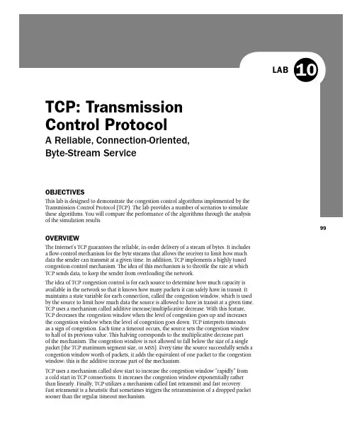
99LABO BJECTIVES This lab is designed to demonstrate the congestion control algorithms implemented by the Transmission Control Protocol (TCP). The lab provides a number of scenarios to simulate these algorithms. You will compare the performance of the algorithms through the analysis of the simulation results.O VERVIEW T he Internet’s TCP guarantees the reliable, in-order delivery of a stream of bytes. It includes a fl ow-control mechanism for the byte streams that allows the receiver to limit how much data the sender can transmit at a given time. In addition, TCP implements a highly tuned congestion-control mechanism. The idea of this mechanism is to throttle the rate at which TCP sends data, to keep the sender from overloading the network.The idea of TCP congestion control is for each source to determine how much capacity is available in the network so that it knows how many packets it can safely have in transit. It maintains a state variable for each connection, called the congestion window, which is used by the source to limit how much data the source is allowed to have in transit at a given time. TCP uses a mechanism called additive increase/multiplicative decrease. With this feature, TCP decreases the congestion window when the level of congestion goes up and increases the congestion window when the level of congestion goes down. TCP interprets timeouts as a sign of congestion. Each time a timeout occurs, the source sets the congestion window to half of its previous value. This halving corresponds to the multiplicative decrease part of the mechanism. The congestion window is not allowed to fall below the size of a single packet (the TCP maximum segment size, or MSS). Every time the source successfully sends a congestion window worth of packets, it adds the equivalent of one packet to the congestion window; this is the additive increase part of the mechanism.TCP uses a mechanism called slow start to increase the congestion window “rapidly” from a cold start in TCP connections. It increases the congestion window exponentially rather than linearly. Finally, TCP utilizes a mechanism called fast retransmit and fast recovery. Fast retransmit is a heuristic that sometimes triggers the retransmission of a dropped packet sooner than the regular timeout mechanism.T CP: Transmission Control ProtocolAReliable, Connection-Oriented, Byte-Stream Service10100Network Simulation Experiments ManualI n this lab, you will set up a network that utilizes TCP as its end-to-end transmission p rotocol,and you will analyze the size of the congestion window with different mechanisms.P RE-LAB ACTIVITIES& Read S ection 5.2 from C omputer Networks: A Systems Approach, 5th Edition.:Go to w and play the following animations:❍T CP Connections❍T CP Multiplexing❍T CP Buffering and Sequencing❍U ser Datagram Protocol (UDP)P ROCEDUREC reate a New Project1. S tart O PNET IT Guru Academic Edition· Choose N ew from the F ile menu.2. S elect P roject and click O K· Name the project <your initials>_TCP, and the scenarioN o_Drop· Click O K.3. I n the S tartup Wizard: Initial Topology dialog box, make sure that C reate Empty Scenariois selected · Click N ext· Select C hoose From Maps from the N etwork Scale list · ClickN ext· Choose U SA from the Map List · Click N ext twice · Click O K.C reate and Confi gure the NetworkI nitialize the network:1. T he O bject Palette dialog box should now be on the top of your project space. If it is notthere, open it by clicking . Make sure that the i nternet_toolbox item is selected fromthe pull-down menu on the object palette.2. A dd to the project workspace the following objects from the palette: A pplication Confi g,P rofi le Confi g, an i p32_Cloud,and two subnets.a. T o add an object from a palette, click its icon in the object palette · Move your mouseto the workspace · Click to drop the object in the desired location · Right-click tofi nish creating objects of that type.3. C lose the palette.4. R ename the objects you added as shown.5. S ave your project.T he i p32_cloud nodemodel represents an IPcloud supporting up to32 serial line interfacesat a selectable data ratethrough which IP traffi ccan be modeled. IP pack-ets arriving on any cloudinterface are routed tothe appropriate outputinterface based on theirdestination IP address.The RIP or OSPF protocolmay be used to auto-matically and dynami-cally create the cloud’srouting tables and selectroutes in an adaptivemanner. This cloudrequires a fi xed amountof time to route eachpacket, as determinedby the P acket Latencyattribute of the node.101C onfi gure the applications:1. R ight-click on the A pplications node · E dit Attributes · Expand the A pplication Defi nitions attribute and set r ows to 1 · Expand the new row · Name the row F TP_Application . a . E xpand the D escription hierarchy · Edit the F TP row as shown (fi rst, you will need to set the S pecial Value to N ot Used while editing the attributes shown):2. C lick O K twice, and S ave your project. C onfi gure the profi les:1. R ight-click on the P rofi les node · E dit Attributes · Expand the P rofi le Confi guration attribute and set r ows to 1 . a . N ame and set the attributes of r ow 0 as shown · Click O K .LAB 10TCP: Transmission Control Protocol102Network Simulation Experiments ManualC onfi gure the West subnet:1. D ouble-click on the W est subnet node. You get an empty workspace, indicating that thesubnet contains no objects.2. O pen the Object palette and make sure that the i nternet_toolbox item is selected fromthe pull-down menu.3. A dd the following items to the subnet workspace: one e thernet_server, one e thernet4_slip8_gtwy router, and connect them with a bidirectional 100_BaseT link ·C lose thepalette ·R ename the objects as shown.4. R ight-click on the S erver_West node ·E dit Attributes:a. E dit A pplication: Supported Services· Set r ows to 1· Set N ame to F TP_Application· Click O K.b. E dit the value of the S erver Address attribute and write down S erver_West.c. E xpand the T CP Parameters hierarchy · Set both F ast Retransmit and F ast Recoveryto D isabled.5. C lick O K, and S ave your project.N ow, you have completed the confi guration of the West subnet. To go back to the top levelof the project and click the G o to next higher levelbutton.C onfi gure the East subnet:1. D ouble-click on the E ast subnet node. You get an empty workspace, indicating that thesubnet contains no objects.2. O pen the Object palette and make sure that the i nternet_toolbox item is selectedfrom the pull-down menu.3. A dd the following items to the subnet workspace: one e thernet_wkstn, one e thernet4_slip8_gtwy router, and connect them with a bidirectional 100_BaseT link ·C lose thepalette · Rename the objects as shown.4. R ight-click on the C lient_East node ·E dit Attributes:a. E xpand the A pplication: Supported Profi les hierarchy · Set r ows to 1· Expand ther ow 0hierarchy · Set P rofi le Name to F TP_Profi le.b. A ssign C lient_ East to the C lient Address attributes.c. E dit the A pplication: Destination Preferences attribute as follows:d. S et r ows to 1· Set S ymbolic Name to F TP Server· Edit A ctual Name· Set r owsto 1· In the new row, assign S erver_West to the N ame column.5. C lick O K three times, and then S ave your project.Y ou have now completed the confi guration of the E ast subnet. To go back to the projectspace, click the G o to next higher levelbutton.T he e thernet4_slip8_gtwy node modelrepresents an IP-basedgateway supporting fourEthernet hub interfacesand eight serial lineinterfaces.103pen the Object palette bidirectional links, connect the P Cloud 1. R ight-click on S erver_West in the W est subnet, and select C hoose Individual Statistics from the pop-up menu. 2. I n the C hoose Results dialog box, choose the following statistic: a . T CP Connection · C ongestion Window Size (bytes) and S ent Segment Sequence Number .lowing capture modes:A ll values:This mode collects every data point from a statistic.S ample: This mode col-lects the data according to a user-specifi ed time interval or sample count. For example, if the time interval is 10, data is sampled and recorded every 10th second. If the sample count is 10, every 10th data point is recorded. All other data points are discarded. B ucket: This mode collects all of the points over the time interval or sample count into a “data bucket” and generates a result from each bucket. This is the default mode.104Network Simulation Experiments Manualb. R ight-click on the C ongestion Window Size (bytes)statistic · Choose C hangeCollection Mode· In the dialog box, check A dvanced· From the drop-downmenu, assign a ll values to C apture mode as shown · Click O K.c. R ight-click on the S ent Segment Sequence Number statistic · Choose C hangeCollection Mode· In the dialog box, check A dvanced· From the drop-downmenu, assign all values to Capture mode.3. C lick O K twice, and S ave your project.4. C lick the G o to next higher levelbutton.C onfi gure the SimulationH ere we need to confi gure the duration of the simulation:1. C lick on and the C onfi gure Simulation window should appear.2. S et the duration to 10.0 minutes· Click O K.D uplicate the ScenarioI n the network we just created, we assumed a perfect network with no discarded packets.Also, we disabled the fast retransmit and fast recovery techniques in TCP. To analyze theeffects of discarded packets and those congestion-control techniques, we will create two addi-tional scenarios.1. S elect D uplicate Scenario from the S cenarios menu, and give it the name D rop_NoFast·Click O K.a. I n the new scenario, right-click on the I P Cloud·E dit Attributes· Assign 0.05%tothe P acket Discard Ratio attribute · Click O K, and S ave your project.2. W hile you are still in the D rop_NoFast scenario, select D uplicate Scenario from theS cenarios menu, and give it the name D rop_Fast.a. I n the D rop_Fast scenario, right-click on S erver_ West, which is inside the W estsubnet ·E dit Attributes· Expand the T CP Parameters hierarchy ·E nable the F astRetransmit attribute · Assign R eno to the F ast Recovery attribute.3. C lick O K, and S ave your project.R un the SimulationT o run the simulation for the three scenarios simultaneously:1. G o to the S cenarios menu · Select M anage Scenarios.2. C hange the values under the R esults column to <collect>(or <recollect>) for the threescenarios. Compare with the following fi gure.3. C lick O K to run the three simulations. Depending on the speed of your processor, thistask may take several seconds to complete.4. A fter the simulation runs complete, click C lose·S ave your project.V iew the ResultsT o view and analyze the results:1. S witch to the D rop_NoFast scenario (the second one) and choose V iew Results from theR esults menu.2. F ully expand the O bject Statistics hierarchy and select the following two results:C ongestion Window Size (bytes)and S ent Segment Sequence Number.T o switch to a sce-nario, choose S witchto Scenario from theS cenarios menu or justpress C trl ؉ <scenarionumber>.W ith f ast retrans-mit, TCP performs aretransmission of whatappears to be the missingsegment, without waitingfor a retransmission timerto expire.A fter fast retransmitsends what appears tobe the missing segment,congestion avoidancebut not slow start is per-formed. This is the f astrecovery algorithm.T he fast retransmit andfast recovery algorithmsare usually implementedtogether (RFC 2001).105LAB 10TCP: Transmission Control Protocol3. C lick S how . The resulting graphs should resemble the ones that follow.4. T o zoom in on the details in the graph, click and drag your mouse to draw a rectangle, as shown in the preceding fi gure. T he graph should be redrawn to resemble the following one:106Network Simulation Experiments ManualN otice the S egment Sequence Number is almost fl at with every drop in the congestionwindow.5. C lose the V iew Results dialog box and select C ompare Results from the R esult menu.6. F ully expand the O bject Statistics hierarchy as shown and select the following result:S ent Segment Sequence Number.7. C lick S how. After you zoom in, the resulting graph should resemble the one shown here.107LAB 10TCP: Transmission Control ProtocolF URTHER READINGSO PNET TCP Model Description: From the P rotocols menu, select T CP · M odel Usage Guide . T ransmission Control Protocol: IETF RFC number 793 ( w /rfc.html ).E XERCISES1. W hy does the S egment Sequence Number remain unchanged (indicated by a horizontal line in the graphs) with every drop in the congestion window?2. A nalyze the graph that compares the S egment Sequence numbers of the three scenarios. Why does the D rop_NoFast scenario have the slowest growth in sequence numbers?3. I n the D rop_NoFast scenario, obtain the overlaid graph that compares S ent Segment Sequence Number with R eceived Segment ACK Number for S erver_West . Explain the graph. H int: Make sure to assign a ll values to the C apture mode of the R eceived Segment ACK Number statistic.4. C reate another scenario as a duplicate of the D rop_Fast scenario. Name the new scenario Q 4_Drop_Fast_Buffer . In the new scenario, edit the attributes of the C lient_East node and assign 65535 to its R eceiver Buffer (bytes) attribute (one of the T CP Parameters ). Generate a graph that shows how the C ongestion Window Size (bytes) of S erver_West gets affected by the increase in the receiver buffer. (Compare the congestion window size graph from the D rop_Fast scenario with the corresponding graph from the Q 4_Drop_Fast_Buffer scenario.)L AB REPORT Prepare a report that follows the guidelines explained in the Introduction Lab. The report should include the answers to the preceding exercises as well as the graphs you generated from the simulation scenarios. Discuss the results you obtained and compare these results with your expectations. Mention any anomalies or unexplained behaviors.。
TCP系列39—拥塞控制—2、拥塞相关算法及基础知识⼀、拥塞控制的相关算法早期的TCP协议只有基于窗⼝的流控(flow control)机制⽽没有拥塞控制机制,因⽽易导致⽹络拥塞。
1988年Jacobson针对TCP在⽹络拥塞控制⽅⾯的不⾜,提出了“慢启动(Slow Start)”和“拥塞避免(Congestion Avoidance)”算法。
1990年Jacobson⼜做了两个修正。
在这⼆⼗来年的发展过程中,与拥塞控制相关的有四个⽐较重要的版本:TCP Tahoe、TCP Reno、TCP NewReno和TCP SACK。
TCP Tahoe是早期的TCP版本,它包括了3个最基本的算法-“慢启动”、“拥塞避免”和“快速重传(Fast Retransmit)”,但是在Tahoe版本中对于超时重传和快速重传的处理相同,⼀旦发⽣重传就会开始慢启动过程。
TCP Reno则在TCP Tahoe基础上增加了“快速恢复(Fast Recovery)”算法,针对快速重传作出特殊处理,避免了⽹络拥塞不严重时采⽤“慢启动”算法⽽造成过度减⼩发送窗⼝尺⼨的现象。
TCP NewReno对TCP Reno中的“快速恢复”算法进⾏了修正,它考虑了⼀个发送窗⼝内多个数据包丢失的情况。
在Reno版中,发送端收到⼀个新的ack number后就退出“快速恢复” 阶段,⽽在NewReno版中,只有当所有的数据包都被确认后才退出“快速恢复”阶段。
TCP SACK关注的也是⼀个窗⼝内多个数据包丢失的情况,它避免了之前版本的TCP重传⼀个窗⼝内所有数据包的情况,包括那些已经被接收端正确接收的数据包,⽽只是重传那些被丢弃的数据包。
传统的TCP拥塞控制算法主要就由慢启动、拥塞避免、快速重传、快速恢复这4个基础算法组成,这四个基础算法在RFC5681规范中进⾏了描述。
后续我们将会分别对这些拥塞控制相关的算法做介绍,在介绍这些拥塞控制的相关算法之前我们先介绍⼀下拥塞控制中的数据包守恒原则和linux中拥塞控制的背景知识,以⽅便后⾯进⾏更进⼀步的介绍。
TCP的拥塞控制1.引⾔计算机⽹络中的带宽、交换结点中的缓存和处理机等,都是⽹络的资源。
在某段时间,若对⽹络中某⼀资源的需求超过了该资源所能提供的可⽤部分,⽹络的性能就会变坏。
这种情况就叫做拥塞。
拥塞控制就是防⽌过多的数据注⼊⽹络中,这样可以使⽹络中的路由器或链路不致过载。
拥塞控制是⼀个全局性的过程,和流量控制不同,流量控制指点对点通信量的控制。
2.慢开始与拥塞避免发送⽅维持⼀个叫做拥塞窗⼝cwnd(congestion window)的状态变量。
拥塞窗⼝的⼤⼩取决于⽹络的拥塞程度,并且动态地在变化。
发送⽅让⾃⼰的发送窗⼝等于拥塞窗⼝,另外考虑到接受⽅的接收能⼒,发送窗⼝可能⼩于拥塞窗⼝。
慢开始算法的思路就是,不要⼀开始就发送⼤量的数据,先探测⼀下⽹络的拥塞程度,也就是说由⼩到⼤逐渐增加拥塞窗⼝的⼤⼩。
这⾥⽤报⽂段的个数的拥塞窗⼝⼤⼩举例说明慢开始算法,实时拥塞窗⼝⼤⼩是以字节为单位的。
如下图:当然收到单个确认但此确认多个数据报的时候就加相应的数值。
所以⼀次传输轮次之后拥塞窗⼝就加倍。
这就是乘法增长,和后⾯的拥塞避免算法的加法增长⽐较。
为了防⽌cwnd增长过⼤引起⽹络拥塞,还需设置⼀个慢开始门限ssthresh状态变量。
ssthresh的⽤法如下:当cwnd<ssthresh时,使⽤慢开始算法。
当cwnd>ssthresh时,改⽤拥塞避免算法。
当cwnd=ssthresh时,慢开始与拥塞避免算法任意。
拥塞避免算法让拥塞窗⼝缓慢增长,即每经过⼀个往返时间RTT就把发送⽅的拥塞窗⼝cwnd加1,⽽不是加倍。
这样拥塞窗⼝按线性规律缓慢增长。
⽆论是在慢开始阶段还是在拥塞避免阶段,只要发送⽅判断⽹络出现拥塞(其根据就是没有收到确认,虽然没有收到确认可能是其他原因的分组丢失,但是因为⽆法判定,所以都当做拥塞来处理),就把慢开始门限设置为出现拥塞时的发送窗⼝⼤⼩的⼀半。
然后把拥塞窗⼝设置为1,执⾏慢开始算法。
TCph方案简介TCph是一种基于TCP协议的网络传输方案。
TCP(Transmission Control Protocol)是一种面向连接的、可靠的、基于字节流的传输协议,广泛用于互联网上的数据传输。
TCph在TCP协议基础上进行了一系列的优化和改进,旨在提升网络传输的效率和性能。
特点1.高效的拥塞控制算法TCph采用了先进的拥塞控制算法,可以根据网络的拥塞程度自适应调整传输速率,避免网络拥塞导致的传输延迟和丢包。
通过精确的拥塞控制,TCph能够在网络状况不佳时仍然保持较高的传输性能。
2.快速的连接建立和关闭过程TCph通过优化TCP的三次握手和四次挥手过程,减少了连接建立和关闭的时间消耗。
相比传统的TCP协议,TCph可以更快速地建立连接,在网络通信的开始和结束阶段节省了宝贵的时间。
3.灵活的数据封包机制TCph引入了灵活的数据封包机制。
传统的TCP协议中,数据通常以固定大小的数据包进行传输,而TCph允许根据实际需求自定义数据包的大小,使得数据传输更加高效、灵活。
4.支持多路径传输TCph支持通过多个路径同时传输数据,从而提高传输的可靠性和性能。
在网络中,存在多条可能的路径连接两个主机,传统的TCP只能使用其中一条路径进行传输,而TCph可以同时利用多条路径,将数据分散传输,减小网络延迟和丢包的风险。
5.更好的流量控制TCph对流量控制做了改进,通过动态控制发送和接收端的窗口大小,使得数据传输更加平稳可靠。
在高延迟和高丢包的网络环境下,TCph能够更好地适应流量波动,保持良好的网络传输性能。
应用场景TCph方案适用于以下场景:1.大规模数据传输在需要传输大规模数据的场景中,TCph能够通过拥塞控制和流量控制等机制,提供高效可靠的数据传输服务。
例如,科学研究中的数据传输、大规模文件的传输等。
2.实时通信实时通信对网络传输的时延和稳定性有较高要求。
TCph方案的拥塞控制算法和流量控制机制能够保证数据在网络中的快速传输,使得实时通信更加稳定、流畅。
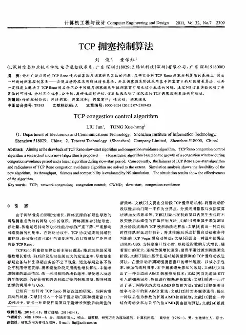
DCWRadio Wave Guard电波卫士基于丢包和网络测量的TCP拥塞控制算法研究综述摘要:拥塞控制一直是网络通信领域的重要研究课题,它可以避免因网络拥塞而导致的传输质量严重下降,同时确保网络带宽的高效利用。
TCP在互联网的发展过程中扮演着不可或缺的重要的角色,是实现网络拥塞控制的重要途径。
随着互联网技术的发展,提出了多种TCP拥塞控制算法,其中基于丢包和网络测量两类算法最为典型。
文章梳理了TCP拥塞控制算法的发展历程,并详细分析了基于丢包和基于网络测量两类算法的原理及优缺点。
关键词:计算机网络;TCP协议;拥塞控制;基于丢包;基于网络测量doi:10.3969/J.ISSN.1672-7274.2022.04.004中图分类号:TP 3 文献标示码:A 文章编码:1672-7274(2022)04-0009-04Abstract: Congestion control has always been an important research topic in the field of network communication. It can avoid the serious reduction in transmission quality caused by the network congestion and ensure the efficient bandwidth utilization. TCP plays an indispensable role in the development of the Internet. It is also an important way to realize network congestion control. With the development of the Internet technology, a variety of TCP congestion control algorithms have been proposed, among which two typical kinds of algorithms include packet loss and network measurement. This paper describes the development history of TCP congestion control algorithms, and analyzes the principles, advantages and disadvantages of two kinds of algorithms, i.e., packet loss-based and network measurement-based, in details.Key words: computer network; TCP protocol; congestion control; packet loss-based; network measurement-basedLI Yinghua, CUI Jiarong(State Radio Monitoring Center, Beijing 100037, China)李英华,崔佳荣通信作者(国家无线电监测中心,北京 100037)Overview of TCP Congestion Control Algorithm Basedon Packets Loss and Network Measurement0 引言随着智能手机和移动互联网的飞速发展,不仅给社会各行各业带来了新的发展机遇,而且通过网络传递的信息流量也变得极其巨大,当信息流量超过网络中部分传输线路的承载能力时,随之而来的问题就是越来越严重的网络拥塞问题。
什么是计算机网络拥塞控制请介绍几种常见的拥塞控制算法计算机网络拥塞控制算法概述计算机网络拥塞控制是指在网络中传输过程中,当网络资源不能满足发送端持续发送数据的需求时,网络中出现了拥塞现象。
为了避免拥塞导致网络性能下降和数据丢失等问题,计算机网络中需要采用拥塞控制算法,以确保网络的正常运行。
拥塞控制算法通过监测网络中的拥塞状态,并根据该状态采取相应的控制措施,以调整发送端的传输速率。
拥塞控制算法的目标是在保证网络资源利用率的同时,避免网络发生拥塞问题。
一、拥塞控制算法之AIMD算法(加性增、乘性减)AIMD算法是一种经典的拥塞控制算法,其核心思想是根据网络的拥塞状态调整发送端的传输速率。
该算法包括两个基本参数:拥塞窗口(cwnd)和慢启动门限(ssthresh)。
慢启动阶段:发送端刚开始传输数据时,以指数级增加拥塞窗口的大小,即指数增长,以快速找到网络的带宽上限。
拥塞避免阶段:当拥塞窗口达到慢启动门限时,改用加性增加的方式,即线性增长,以避免发送速率过快导致网络拥塞。
拥塞发生阶段:当网络发生拥塞时,拥塞窗口会进行乘性减小,以防止进一步恶化网络拥塞。
AIMD算法通过不断调整发送速率,根据网络的拥塞状态来合理分配网络资源,从而实现拥塞控制。
二、拥塞控制算法之TCP Reno算法TCP Reno是TCP协议的一种拥塞控制算法,其基于AIMD算法进行了改进。
TCP Reno算法引入了拥塞避免阶段的快速恢复机制,以更加灵活地应对网络拥塞。
当出现拥塞时,TCP Reno算法会将慢启动门限设置为当前拥塞窗口的一半,并将拥塞窗口大小重置为1,以进行快速恢复,提高网络的传输效率。
TCP Reno算法在拥塞发生阶段,通过加性增加与乘性减小相结合的方式,根据网络的拥塞状况进行控制,以实现拥塞控制。
三、拥塞控制算法之TCP Vegas算法TCP Vegas算法是一种基于时延控制的拥塞控制算法,它通过监测网络的时延变化来判断网络是否拥塞。
计算机网络中的网络拥塞控制算法网络拥塞控制算法是计算机网络中的重要内容,它的作用是通过控制网络中的数据流量,使得网络运行在一个合理的负载范围内,确保网络的稳定性和性能优化。
本文将介绍几种经典的网络拥塞控制算法,包括TCP拥塞控制算法、网络测量与反馈、网络公平性控制等。
一、TCP拥塞控制算法TCP(传输控制协议)是互联网中最重要的传输协议之一,也是大多数应用层协议的基础。
TCP拥塞控制算法的核心思想是通过监测网络的拥塞状态,并按照一定的规则调整数据发送速率,以避免网络拥塞的发生。
1. TCP Tahoe算法TCP Tahoe算法是早期TCP拥塞控制算法中最基础的一种。
它的主要原理是当检测到网络发生拥塞时,将拥塞窗口减少到一个很小的值,然后进入慢启动阶段,逐渐增大拥塞窗口并监听网络状态,一旦再次发生拥塞,重复上述过程。
2. TCP Reno算法TCP Reno算法是TCP拥塞控制算法的一种改进版本,它在Tahoe算法的基础上引入了快速恢复机制。
当网络发生拥塞时,TCP Reno将拥塞窗口减半,并将拥塞窗口动态调整为一个合理的值,在一定的时间内接收到新的ACK确认时,快速恢复到正常的拥塞窗口大小。
3. TCP NewReno算法TCP NewReno算法是对TCP Reno算法的进一步改进,主要针对了发生多个数据包丢失的情况。
在网络发生拥塞时,TCP NewReno通过接收到的SACK(选择性确认)报文信息,恢复丢失的数据包,并根据丢失的数据包数量进行对应的拥塞窗口调整。
二、网络测量与反馈除了TCP拥塞控制算法,网络测量与反馈也是网络拥塞控制中的重要环节,它通过实时监测网络负载情况,并将相关信息反馈给数据发送端,以便控制数据发送速率。
1. 基于ICMP的网络测量ICMP(Internet控制报文协议)是互联网中的一种网络层协议,它可以用于测量网络的延迟和丢包情况。
通过发送ICMP报文并测量响应时间,可以估计网络的负载情况,并根据测量结果调整数据发送速率。