什么是深孔加工
- 格式:docx
- 大小:19.88 KB
- 文档页数:1

深方孔加工的几种工艺方法深方孔加工是金属加工工艺中的重要环节,它能够为人们创造出艺术美观及精准的产品。
对于企业来说,深方孔加工也是一种利润提升的手段,因为它成本低、效率高。
深方孔加工技术有很多种,下面就介绍几种常用的深孔加工方法:1、钻孔加工:钻孔加工技术是最基本的深孔加工方法,该工艺可以用于制造陆地、海洋、航空等种类的精密孔洞。
此外,该工艺还可以实现深度的加工,因此它非常的受欢迎。
2、镗孔加工:镗孔加工技术使用的是磨轮转动的镗头进行加工,它可以实现精确的厚度、直径和深度加工,也可以实现不同方向的加工。
它具有高精度、低能耗、高效率等特点。
3、切孔加工:切孔加工技术利用高速旋转的刀具进行加工,它是一种快速精准的加工方法,它可以实现精确的孔洞的加工,如低精度的平面、倒角等加工。
4、拉切孔加工:拉切孔加工是拉刀用于切削孔洞的技术,主要用于加工金属零件。
它需要先将金属切片裁切成两片,再将这两片金属切片中间拉开,形成孔洞,在这个过程中,拉刀会将金属切片中间的物料切除,最终实现精确的孔洞加工。
第二部分:方孔加工的优势无论是钻孔、镗孔、切孔、拉切孔还是其他类型的深孔加工,都具有一定的优势。
1、精度高:深孔加工的精度比一般的加工方法要高的多,它们可以实现微米级别的精度,使产品更加精确,从而提升产品质量及美观度。
2、效率高:深孔加工技术拥有较快的切削速度,能够大大提高加工效率,节省加工成本,满足客户的需求。
3、生产成本低:深孔加工的成本比传统的加工方式要低的多,这不仅仅是因为它的生产效率高,而且深孔加工所需要的机床和刀具也很实惠,这可以大大降低企业的制造成本。
第三部分:孔加工的限制虽然深孔加工的优势很明显,但它也有一定的局限性。
1、加工复杂度强:深孔加工的复杂度很强,要求技术精湛,操作过程要求一步到位,如果操作不当,会产生质量问题。
2、切屑处理:深孔加工需要清除大量的切屑,这需要较强的切屑处理能力,如果切屑处理形式不当,会影响孔洞加工的效果。
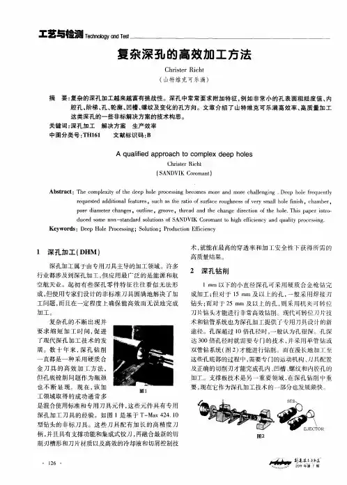
BTA深孔钻的结构特点及加工原理要点bta深孔钻是内排屑深孔钻的一种典型结构,它是在单刃内排屑深孔钻的基础上改进而成,其切削刃呈双面错齿状,切屑从双面切下,并经双面排屑孔进入钻杆排出孔外。
bta深孔钻切削力分布均匀,分屑、断屑性能好,钻削平稳可靠,钻削出的深孔直线性好。
1、BTA深孔钻的结构特点BTA深孔钻具有以下结构特点:(1)刀体上分布有外刃刀片、中刃刀片、内刃刀片、导向块和双面排屑孔,并通过刀体上的浅牙多头矩形螺纹与空心钻杆联接。
(2)钻芯部分由内刀刃代替了麻花钻的横刃,从而克服了麻花钻横刃较长、轴向阻力较大的缺点;由于钻芯相对于钻孔轴心线偏移了一段距离,加工时钻芯处刀刃低于中心处刀刃,因此会形成一个导向芯柱,使钻头具有较好的导向性,钻孔时不易偏斜,该导向芯柱增长到一定长度后会自行折断并随切屑一起排出。
(3)主刀刃采用非对称的分段、交错排列形式,可保证分屑可靠,并避免用整体硬质合金刀片磨削卷屑槽、分屑槽时易产生裂纹的情况。
(4)刀片材料可采用几种不同牌号的硬质合金,以适应各部分结构对耐磨性和强度的不同要求,如钻芯部分切削速度低、切削力大,在切屑挤压作用下易发生崩刃,可选用韧性较好的硬质合金刀片;钻头外缘部分则可选用耐磨性较好的硬质合金刀片。
2、BTA深孔钻的加工原理BTA深孔钻在普通车床上的工作情况:被加工工件由车床大拖板上的v形铁定位并用螺栓压板夹紧。
钻孔加工时,钻杆由主轴内的专用夹头夹紧并在主轴带动下旋转,工件则由大拖板带动作进给运动。
机床工作台上安装了进液器,并通过o形密封圈与工件左端面密封连接。
加压切削液由进液器的进液口注入,经过钻杆外径与孔壁间的缝隙流入切削区,对进行冷却,切屑随同切削液一起由钻杆内孔通过专用夹头的出液口从排液箱排出。
切削液可采用浓度5%的乳化液;切削用量可选用:v=60~90m/min,s=0.035~0.23mm/r。
由于钻杆细长,容易变形,因此在机床导轨上安装了活动中心支承,可对钻杆的任意位置进行支承。
加工中心钻深孔的编程方法加工中心是一种多功能的数控机床,能够进行多种加工操作,包括钻孔。
钻深孔是指钻孔深度较大的孔径。
进行钻深孔加工的编程方法需要考虑到以下几个方面。
首先,需要确定孔径和孔深。
在进行编程之前,需要明确要加工的钻孔的孔径和孔深。
这是编程的基础,也是后续计算加工参数和路径的依据。
其次,需要计算切削参数。
切削参数包括主轴转速、进给速度和切削进给量等。
主轴转速的选择需要考虑材料的硬度和刀具的耐用性。
进给速度的选择需要考虑加工的效率和表面质量。
切削进给量的选择需要考虑刀具和工件的强度和刚性等因素。
然后,需要选择合适的刀具。
钻深孔加工需要选择合适的直柄钻头或深孔钻头。
钻头的选择需要考虑到孔径和孔深,以及材料的硬度和加工精度等因素。
较大的孔径和较深的孔深通常需要较长的钻头和更大的冷却液流量。
接着,需要编写加工程序。
钻深孔加工的编程方法通常有两种:点位编程和插补编程。
点位编程是指根据孔径和孔深,计算每个点的坐标并依次钻孔。
插补编程是指根据加工路径和切削参数,通过插补运动产生连续的切削轨迹。
点位编程适用于简单的孔径和孔深,而插补编程适用于复杂的孔形和大批量的钻深孔加工。
最后,需要进行程序验证和优化。
在进行实际加工之前,需要通过模拟和仿真等方法对加工程序进行验证。
在验证过程中,需要检查加工轨迹、切削参数和表面质量等方面是否满足要求。
如果存在问题,需要及时进行调整和优化。
总之,钻深孔的编程方法需要综合考虑孔径和孔深、切削参数、刀具选择、加工程序编写和程序验证等因素。
只有在充分理解和合理运用这些方法的基础上,才能有效地进行钻深孔加工。
单管内排泄深孔加工系统(BTA)结构原理:钻头柄部有方牙螺纹、钻杆相连接,有压力的切削液进入输油器通过钻杆外部环状空隙流向切削刃部,将切削刃上的切屑反向压入钻头出屑口,经钻杆中空内腔向后排出至积屑盘。
切削液经过滤网回落到油箱,若干层过滤网后重新被供油泵抽出反复使用。
SIED实体钻设计指导思想:排屑方式:内外排屑实体钻在力学性能钻头与钻杆连接方式等对比,选定单管内排屑jg为基本型改进。
用单边刃+2导向条传统头部造型。
出屑口:fai35mm以下sied实体钻用单出屑口利于钻头结构简化和降低成本,更大钻头用双出屑口,利用钻头稳定切削和用机夹jg。
不设断屑台使钻头多次可磨性。
排屑通道供油通道,采取一切措施加大排屑通道平面面积,特别钻头喉部。
钻头与钻杆连接:fai11mm以上内排屑深孔钻用方牙螺纹结构,超长杆用同样连接方法加长。
Sied实体钻具有优良结构工艺性,有利于专业化cad/CAM/栾性制造。
SIED抽屑器排屑机理:强大抽屑功能抽屑装置,加大钻杆末端与钻头喉部压力差提高切屑通过喉部速度,降低堵屑。
结构革新扩大喉部和钻杆内腔切屑通道截面积改进喉部造型使切屑顺畅通过。
合理分配内外宽度,外刃后设分屑刃缩小切屑宽度,深孔直径↓排屑难↑,钻头直径↓加工难↑,错齿钻在大直径深孔加工中有优势不排除将出屑口作为大直径SIED钻结构的选择。
SIED抽屑器结构原理:切削液由液压泵输出后两分支通入输油气和抽屑器,产生高速射流和负压,由独立调压阀调制最佳抽屑状态。
喷嘴副间隙可调。
主设计参数经优化保证最佳抽屑效力,据孔径设计出三种标准型抽屑器,可用于其他内排屑深孔钻床。
最高油压为3.5mpa,对液压系统密封要求不高。
枪钻缺陷结构:钻头与钻杆不可拆卸须整体更换增加辅助时间。
钻杆薄壁无缝管轧成扭转刚度弯曲刚度低进给量受限。
钻杆外径壁厚与钻头存在严格比例关系,钻头配制专用钻杆售价昂贵。
钻头出油孔面积小加工油压要求高。
钻杆为整体全长由孔深决定相差大时用不同枪钻。
北方工业大学科目机械振动-精密深孔镗削中镗杆振动问题学院机电工程学院专业班级机研-12学生姓名指导教师撰写日期:2012年12月12日摘要在机械制造业中,一般规定孔深L 与孔径d 之比大于5,即L/d>5 的孔称为深孔。
深孔加工是处于封闭或半封闭状态下进行的,不能直接观察到刀具的切削情况;且受孔径尺寸限制,刀具直径小,悬伸长,刚性差;切屑不易排出,切削热不易传散,因此深孔加工一直是金属切削领域内公认的技术难题。
而对于两端孔径小,中间孔径大的瓶腔深孔加工则难度更大,除了存在上述一般深孔加工的问题外,还要求实现镗刀块的伸出、夹紧、松开、缩回等动作,且受入口直径的限制,镗杆的刚性问题及振动问题变得更加尖锐。
因此精密小深孔加工技术的研究在理论和实践上都具有重要意义。
经过深孔镗削过程中的自激振动分析、深孔镗杆进行了静力学和动力学理论分析、对深孔镗杆进行ANSYS分析、深孔镗杆的模态分析,有一些减小振动的方法可以利用,如合理选择刀具几何形状、提高工艺系统的抗振性、采用减振装置、合理调整振型的刚度比、超声波方法、镗杆结构优化、智能镗杆颤振监测实验系统、镗削振动主动控制、设计辅助结构等方法等等。
关键词:深孔;镗削;减振目录目录 (3)1机械振动概况 (4)1.1机械振动对机械加工的影响 (4)1.2深孔加工的振动问题 (4)2精密振动切削工艺中的振动问题 (4)2.1项目简介 (4)2.1.1项目中的振动 (4)2.1.2项目镗削工序的振动分析 (4)3深孔镗削过程中的振动分析 (6)3.1深孔镗削过程中的自激振动 (6)3.2深孔镗杆进行了静力学和动力学理论分析 (7)3.3对深孔镗杆进行ANSYS分析 (9)3.4深孔镗杆的模态分析 (10)4减小深孔镗削中振动的方法 (11)4.1概述 (11)4.2超声波方法 (11)4.3镗杆结构优化 (13)4.4智能镗杆颤振监测实验系统 (13)4.5镗削振动主动控制 (14)4.6深孔镗削加减振措施后效果 (15)5.总结 (15)参考文献 (16)1机械振动概况1.1机械振动对机械加工的影响在机械加工过程中,工艺系统的振动会破坏刀具与工件之间正常的运动轨迹,给机械加工带来较大的危害,具体表现在以下几个方面:①影响加工表面质量,频率低时产生波纹,频率高时产生微观不平度;②降低生产效率,加工中的振动制约了切削用量的提高,严重时甚至使切削不能正常进行;③缩短刀具、机床等的使用寿命;④振动产生的噪声污染了环境。
深孔加工的几种方法(一)深孔加工的几种方法1. 钻孔•钻孔是一种常见且基本的深孔加工方法。
•通过使用钻头在工件上创建孔。
•钻孔适用于各种材料,可以进行直孔和斜孔加工。
2. 拉铆•拉铆是一种用于连接两个或多个薄板的深孔加工方法。
•通过钻孔的方式,在两个薄板上创建孔。
•然后使用铆钉将薄板紧密连接在一起。
3. 精铣•精铣是一种通过旋转刀具的方式进行深孔加工的方法。
•切削刀具旋转并移动,将材料的一部分切割掉。
•精铣可以创造出精确的形状和尺寸。
4. 火花加工•火花加工是一种通过放电的方式进行深孔加工的方法。
•通过电极和工件之间的放电,将材料从工件上腐蚀掉。
•火花加工适用于硬质材料,如金属、陶瓷等。
5. 镗削•镗削是一种通过多刃切削刀具的方式进行深孔加工的方法。
•镗削可以用来加工直径较大的孔。
•切削刀具在工件上旋转并移动,逐渐将孔扩大到所需大小。
6. 深孔钻削•深孔钻削是一种通过专用的深孔钻床进行深孔加工的方法。
•通过钻头在工件上连续钻孔。
•深孔钻削适用于加工长孔和深孔。
以上是一些常见的深孔加工方法,每种方法适用于不同的工件和加工需求。
根据具体的情况选择合适的方法,可以提高加工效率和加工质量。
7. 深孔铣削•深孔铣削是一种通过旋转刀具进行深孔加工的方法。
•使用专用的深孔铣削刀具,在工件上进行切削。
•深孔铣削适用于加工深度较大的孔。
8. 螺纹加工•螺纹加工是一种通过切削的方式在工件上创造螺纹的方法。
•可以使用螺纹刀具,将螺纹切削到孔的内壁。
•螺纹加工常用于制作螺纹孔或螺纹轴。
9. 镗磨•镗磨是一种结合镗削和磨削的深孔加工方法。
•首先使用镗削工具将孔钻至一定尺寸,然后使用磨削工具将孔进行精细加工。
•镗磨可用于加工高精度和高表面质量要求的深孔。
10. 激光加工•激光加工是一种非接触式的深孔加工方法。
•使用激光束将材料腐蚀或熔化,以形成深孔。
•激光加工适用于各种材料,可以实现高精度和高效率。
总结:深孔加工是一项复杂的工艺,需要根据工件的材料、尺寸和加工要求选择合适的方法。

The deep processing and Boring ToolsOn the deep processing of the technological requirementsDeep processing, is the top priority of this design. The so-called deep hole, the hole is that when processing the ratio of length and diameter of about 10 times, often on the accuracy and surface finish requirements and higher, the use of processing methods in general are more difficult to meet.I. Deep processing issues that must be addressed:1) poor tool rigidity slender and easy to cause the tool deflection and friction with the hole wall, and therefore the head knives are correctly oriented to ensure the introduction of sets; At the same time, bearing in accordance with the need for holders to reduce the deformation and vibration Arbor.2) is not easy from cuttings, the use of feed grade or high-pressure cutting fluid through the inner row and outer row chip from the tool structure.3) tool cooling difficulties, access to high-pressure cutting fluid cooling of the tool fully.II. Deep processing of type:Combine the characteristics of deep-hole machining, deep hole processing technology on the difficulties, the method has been overcome.1) Deep processing grade feed:Ordinary twist drill head in cast iron or steel pieces on the 6 ~ 10mm diameter drill hole below, the general should not be a deep-drilling of 6 ~ 10 times greater than the aperture. When the direction of horizontal drilling, the steel pieces in the deep drilling should not last more than 6 times the diameter, in the cast iron up to about 10 times the aperture. If the processing of the hole depth of more than this range, can be classified into methods for processing, that is, in the drilling process, so that bit processing automatically after a certain depth from the workpiece in order to discharge swarf and cooling, and then re-forward processing, constant back and forth until the process has finished (each drill deep, cast iron pieces from 3 to 6 times the diameter; steel pieces from 0.5 ~ 2 times the aperture, the deeper hole when taking a small value). This process is suitable for drilling deep holes of small diameter, but the productivity and precision mechanics are relatively low.2) feeding a deep-hole processingIt is mainly used various types of special segment, and with the next shot, transmission-oriented systems, such as cutting fluid input in thedeep-hole drilling machine, hinges, boring and the presentation materials. Discharged from the way the chip can be especially Chip (on the hinge, there is also boring things forward or backward Chip) and with Chip; froma number of cutting edge, can be divided into single-blade, double-edged and multi-blade, cutting edge can be high-speed steel or carbide. Cutter head have a different number of block-oriented support in theprocess-oriented role play to ensure flatness of the hole, but also from the role of squeezed light to improve the processing of the surface finish hole.Chip has a deep-hole drilling in a single tube and dual tube Chip Chip (ie, jet drilling). Chip fear of double tube drill pipe than Chip Chip fear deep-hole drilling and drilling outside the processing efficiency and higher accuracy. The deep hole on the barrier is expected to set at the completion of unloading Nesting Nesting knife, cut off the mandrel fitted with a knife and the knife folder to make it against the mandrel, the feed through a dedicated device to cut off, cut to the core diameter rod 4 / 5 ~ 5 / 6 will be back to cut off the knife, a little outside the mandrel to break out.In general, the use of inside than outside the Chip Chip processing large diameter, obtained by processing high precision and surface finish. III. The main points of deep-hole processingMachine tools and processing of the previous process, and attention should check the following:1) axis-oriented tool sets, Bar sets of bearings, such as the centerline of the workpiece support different sets of axis degrees should meet the requirement.2) check whether the system is cutting fluid flow and normal work is a multi-edge special deep-hole drilling with Chip (jet drilling suction) of the spray suction effect, in particular, should seriously check.3) the workpiece should be the upper end of the processing center hole, and to avoid drilling in the slope.4) Does the shape of a normal chip. With the workpiece material, tool geometry, cutting parameters and so on. The two separated by a certain direction of each curl inward cutting the best shape to avoid the formation of the ribbon cuttings straight.5) The higher the speed of processing through-hole, when the drill bit is about to pass, it is best to stop or deceleration to prevent damage to the bit and the exit.6) should be avoided in the processing of parking, such as the need to stop, they should first stop into the tool and return to some distance, and then stop the pump and the rotation of the main campaign to prevent the tool in the hole a "killed" phenomenon.Productivity increases through advancements in boring tool designs. Boring tools are often regarded as the best method for producing accurateholes in parts of every size and configuration. A steady stream of productivity increases have come about through advancements in the design of boring tools.Four newer developments include:■ digital readout displays in precisio n boring heads;■ aluminum construction;■ combination boring tools; and■ self-balancing tools.Digital Readout DisplaysCNC and coordinate measuring machines that utilize digital displays have been around since the beginning of NC technology. And, micrometers and vernier calipers with electronic digital displays are commonplace.Adapting electronic display technology to precision boring has been slower because of the coolant and the high rotational speeds used when boring.Coolant has a way of getting into any tool used on a machining center, so extreme care must be taken to prevent it from entering any electronic device.With newer designs, throughcoolant tools are possible. The coolant is directed through internal passages that are completely isolated from the digital display. The exterior of the tool is also sealed to keep coolant from contacting the electronics.High rotational speeds, centrifugal loads and any inherent unbalance can cause vibration severe enough to damage sensitive digital displays. High rotational speeds are achievable by using an internal balancing feature that reduces or eliminates this potentially harmful vibration. Precision boring heads are available with digital displays that can handle speeds up to 16,000 rpm.The digital display of the boring head shows the movement of the boring tool slide, rather than the rotation of a lead screw. Because the boring bar is mounted in the tool slide, the digital readings are a true measurement of tool movement. The digital display gives a true backlash-free reading. This feature enables quicker and more accurate diameter changes and allows for deflection or tool wear compensation.Most boring tool settings are determined with the cut-and-measure process.This involves boring a small portion of the hole being produced, then gaging it. Frequently, this means the boring tool is removed from the machine and put on a tool presetter in order to make the small corrections necessary to obtain the proper hole size.The process is required because the vernier dials commonly seen on boring heads can be difficult to read and set on the machine. However, the process introduces the possibility of boring oversize holes and scrapping the part.Because of unpredictable tool-point deflection in the machine setup, the cut-and-measure process is required. However, with an easy-to-read digital display, small diameter changes are possible right on the machine. Diameter changes of 0.0001" can be made with the tool in the machine spindle. If the tool must be removed from the machine to change diameter settings because of spindle access restrictions, the digital display makes this a quick and precise task.Aluminum ConstructionAluminum’s relatively light weight makes it a common material for to ol bodies. Weight reduction is critical with today’s higher-speed, and sometimes lighter, CNC machines.Most of these machines’ toolchangers have weight limits. By using aluminum construction, boring tools can be produced that stay under these weight limits while still being able to bore holes from 4" in diameter on up. (Generally, tools smaller than 4" in diameter, whether made of aluminum or steel, meet toolchanger weight limits.) The reduced weight lessens spindle deflection, which results in more accurate bores. Thereis also less wear and tear on the machine spindle itself.There is a considerable productivity gain if the need for loading large, heavy boring tools into the machine by hand or with the aid of an overhead crane is eliminated. For example, one shop in Kansas replaced a 14"-dia. steel boring tool that weighed approximately 40 lbs. with an aluminum tool that weighed less than 25 lbs. The customer went from manual loading witha jib crane to using his automatic toolchanger.Setting a boring tool with a digital display can be performed withoutremoving the tool from the machine.关于深孔加工的工艺要求深孔加工,是本设计的重中之重。
小孔深孔加工方法
嘿,咱今天聊聊小孔深孔加工方法。
我跟你说啊,有一回我去一个机械厂参观,正好看到他们在加工那种小孔深孔。
我一走进车间,就听到各种机器嗡嗡作响。
在一个角落里,几个工人正围着一台看着很厉害的机器。
我好奇地凑过去瞧。
那机器上夹着一个金属工件,上面有个小小的孔,他们要把这个孔加工得更深。
工人师傅们先拿出一个特别细的钻头,细得跟头发丝似的。
他们小心地把钻头安装到机器上,动作轻柔得就像在给宝贝穿衣服。
然后打开机器,钻头就开始慢慢旋转起来。
随着钻头的转动,一点点金属屑飞了出来。
这时候,一个师傅拿着一个小喷壶,时不时地给钻头喷点冷却液。
他跟我说,这冷却液可重要了,不然钻头一会儿就得烧坏。
我看着那喷出来的冷却液,就像给钻头洗了个凉水澡。
加工的过程可慢了,感觉就像蜗牛在爬。
师傅们眼睛紧紧地盯着那个小孔,生怕出一点差错。
过了好久好久,那个小孔终于变得越来越深了。
等加工完了,师傅们脸上露出满
意的笑容,就像完成了一件了不起的大事。
这一趟参观下来,我可算是见识到了小孔深孔加工的不容易。
以后再看到那些有小孔深孔的零件,我就会想起师傅们在车间里认真加工的样子。
所以说啊,小孔深孔加工方法还真不简单,得靠师傅们的细心和耐心才能做好。
目录目录 (I)摘要................................................................................................................................................. I II ABSTRACT .................................................................................................................................... I V 第一章绪论. (1)1.1引言 (1)1.2深孔加工技术国内外现状 (1)1.2.1国外深孔加工技术发展现状 (1)1.2.2国内深孔加工技术发展现状 (3)1.3 深孔加工的特点 (4)1.4课题研究的背景、意义以及发展趋势 (5)1.5 课题的研究内容 (6)第二章深孔加工方法及问题分析 (7)2.1 深孔加工方法 (7)2.1.1 扁钻 (7)2.1.2 枪钻 (8)2.1.3 BTA深孔加工系统 (9)2.1.4 双管喷吸钻系统 (10)2.1.5 DF(Double Feeder system)系统 (11)2.1.6 单管内排屑深孔喷吸加工技术(SIED技术) (12)2.1.7 深孔扩钻(Counterboring)技术 (12)2.2 常用深孔加工方法对比分析 (13)2.3 深孔加工注意事项与问题分析 (14)2.3.1加工时应注意的问题 (14)2.3.2深孔钻常见问题及产生原因 (14)2.4深孔加工系统的选用 (15)2.5本章小结 (15)第三章深孔钻削的力学特性分析 (15)3.1深孔钻削刀具的力学模型 (16)3.1.1 BTA内排屑深孔钻的力学模型 (16)3.2深孔钻削各切削力的求解 (18)3.2.1钻削力的测量 (18)3. 2. 2钻削力分量求解 (19)3. 3导向块位置角的分布分析 (20)3.4 本章小结 (22)4.1 深孔钻削加工的动态钻削力 (22)4.2机床振动理论 (23)4.2.1金属切削过程的自激振动 (24)4.2.2强迫再生颤振 (31)4.2.3提高机床切削稳定性的基本途径 (33)4.3深孔钻削过程中的振动分析 (34)4.3.1深孔钻削加工过程的动力学模型 (34)4.3.2瞬时动态钻削力的计算 (36)4.3.3深孔钻削加工过程的振动分析 (37)4.4 本章小结 (38)第五章深孔钻削仿真分析 (38)5.1 深孔钻削加工仿真分析 (39)5.2本章小结 (47)第六章结论 (47)参考文献 (49)致谢 (52)摘要随着科学技术的进步,产品的更新换代周期越来越短,新型的高硬度、高强度、高精度零件不断涌现,无论是对深孔加工的效率、加工的质量,还是加工成本都提出了更高的要求。
深孔零件加工技术浅谈作者:孔令超郭晓丽来源:《职业·中旬》2012年第05期深孔零件加工是机械加工中的一个难题,尤其是细长孔的加工。
难点在于刀具细长、刚度差、强度低、易引起刀具偏斜,且散热困难等问题出现,从而达不到加工质量的要求。
因此,在没有深孔加工的专用设备时,用普通设备加工深孔、细长孔,刀具和夹具的设计非常重要。
一、深孔、细长孔加工方法深孔、细长孔加工过程:打中心孔—钻孔—一次扩孔—二次扩孔—铰孔例:加工图1所示的细长孔定位套零件。
深孔加工是指孔深与直径之比L/d≥5的孔。
大型企业对深孔零件的加工,主要采用专用的设备和特制辅助工装设备加工。
对于中小型的加工企业只能在普通机床上,采用简易的工装对深细长孔进行加工。
如图1所示的细长孔零件,因孔壁较薄,直接用11.8mm或11.9mm的钻头钻孔,一次切削产生的热量大,一次钻削加工孔壁粗糙度并且尺寸精度也较差,不宜直接用来进行精铰孔加工。
因此,为了减小热变形和残余应力对精加工的影响,操作者应采取扩孔加工方法并充分浇注冷却液的方法减小粗加工留下的加工误差,以提高后续加工精度。
二、钻头的刃磨要求齿轮定位套零件的加工,由于尺寸精度要求较高,所以,钻头的刃磨非常重要,尤其是对最后一次扩孔钻头的刃磨有特殊的要求。
因此,操作者需要改进钻头的几何参数,操作要求如下:一是在两主切削刃上修磨出第二锋角,一般不超过75°,并在外缘刀尖角处研磨出两边R0.2~0.5mm 的圆弧过渡刃,粗糙度达Ra0.4μm以下,且两个过渡刃相互对称,高度一致,以增大刀尖外缘处的强度和耐磨度,改善散热条件,减小孔壁的残留面积高度。
二是将前端棱边磨窄,只保留0.1~0.2mm 的宽度,修磨长度为4~5mm,以减小棱边与孔壁的摩擦。
三是修磨副切削刃、前刀面和后刀面,用400号以上油石研磨,最好用600号以上油石研磨,研磨各部位粗糙度达到Ra0.4~Ra0.2μm。
三、铰孔及注意事项1.浮动铰刀的设计实践证明,扩孔有纠正形状位置精度的能力,而铰刀铰孔只能保证尺寸、形状精度和减小孔的表面粗糙度,但不能纠正孔的位置精度,有时,由于机床的振动,甚至铰出的孔会变成椭圆形。
常见的深孔加工方法【德州三嘉机器】长径比大于6孔,一般称为深孔。
深孔钻床在加工时依照不一样的需求选用不一样的加工方法,深孔钻床按排屑方法分为外排屑和内排屑两类。
外排屑的有枪钻、深孔扁钻和深孔麻花钻等;枪钻加工孔径比可达200,加工孔径在Φ40以下。
内排屑的因所用的加工体系不一样,分BTA 深孔钻、喷吸钻和DF深孔钻3种,BTA加工一般孔径Φ30以上。
#详情查看#【德州三嘉机器:深孔加工】【深孔钻床进行深孔加工】1.使用数控深孔钻床加工深孔,合理的设备结构、良好的减震性能、尽可能小的径向跳动是保证深孔的加工精度、重复定位精度及表面粗糙度所必需的;2.合适的数控深孔钻床的钻头几何形状可以使深孔加工更加高效;3.采用高压冷却系统,可以顺利排屑,可以提高主轴转速及进刀速率,还可以延长刀具寿命。
4.高压冷却、钻头精确的几何形状、刀具材料、切削参数的合理选择是深孔加工的重要影响因素,每个因素都会影响到孔的尺寸精度、表面粗糙度、加工周期及刀具寿命等。
总结:一种较佳的数控深孔钻床工艺组合是采用高压冷却系统、带有顺畅的排屑通道、具有涂层的合金刀具并只需单次退刀即可完成。
以上条件是在数控深孔钻床上成功实现深孔加工的基本需求。
【常见的深孔加工方法】①中小型模具的冷却水孔及加热孔的深孔钻加工,常用普通钻头或加长钻头在立式钻床、摇臂钻床上加工,加工时应注意及时排屑、冷却,进给量要小,防止孔偏斜。
②中、大型模具的孔一般在摇臂钻床、镗床及深孔钻床上加工,较先进的方法是可在加工中心机床上与其他孔一起加工。
③过长的低精度孔也可采用划线后从两头对钻。
④垂直度要求较高的孔应采取一定的工艺措施予以导向,如采用钻模等。
钻深孔时还应注意:a.钻孔时一般钻深到直径的3倍时,需将钻头提出排屑,以后每进一定深度,钻头均应退出排屑,以免钻头因切屑阻塞而折断。
b.有的深孔深度超过钻头的总长度或更深一些,这时可使用加长杆钻头或连接杆钻头钻孔,这两种钻头可外购或自制。
深孔加工技术加工深孔时采用穿轴式高压冷却方式将钻屑冲刷到孔外。
该技术代替了周期退刀排屑,减少了潜在的破坏与刀具磨损,并提高了生产率。
采用立式加工中心进行孔加工是最普通的加工方法,但是当进行深孔加工时,则会遇到很大困难。
不过,目前已经有许多有效的方法来解决这个难题。
目标在于精确地加工出这些孔,并达到良好的重复定位精度和表面精度以及良好的经济性。
成功的深孔加工中最重要的因素是对加工原理的理解。
你必须了解当钻孔时在孔的内部所发生的一切,并知道如何应用这些知识来指导你采用最有效的技术方法。
深孔加工的优化编辑解决深孔加工的三个主要问题:排出钻屑且不能损伤工件表面;采用冷却液来保持钻具与工件的冷却效果;以及使加工周期最小化。
其它重要的因素包括加工精度,重复定位精度及表面粗糙度。
通常来说,深孔是由孔的直径与深度的比例来定义的。
习惯上将大于等于5:1的认为是深孔加工。
钻屑必须足够小才能从钻槽中排出。
长的带状钻屑可以破坏表面精度并造成过早的刀具磨损与断裂。
冷却液必须到达刀具的顶端来保持钻具与工件的冷却,以及迫使钻屑从孔内排出。
稳固的设备结构与良好的减震性能以及很小的轴向跳动是获取加工精度,重复定位精度及表面粗糙度所必需的。
当然,合适的钻头几何形状可以使深孔加工更加高效。
控制钻屑的尺寸和形状一些材料形成了细小的钻屑,且能够通过钻槽容易地排出。
有些材料却形成长的带状钻屑。
一种控制钻屑尺寸和形状的方法是采用特殊的加工周期。
深孔加工与退刀相结合可以破碎钻屑,令其小的足以从钻槽排出,并且不会造成表面的损伤,可避免钻具的过早磨损。
一般来说,有两种深孔加工方法。
一种采用均分退刀深度来达到最终的深度。
另一种是不同的退刀深度,每次的深度逐步递减。
当冷却液不能到达深孔的底部时,切屑很可能堵塞了钻槽,使热量聚集而损坏钻具与工件。
大多数加工设备的控制系统提供了深孔加工的钻削加工,控制钻具钻入材料特定的距离后,从孔内完全退出,然后再钻入孔中。
钛合金等的深孔螺纹加工一直是一个棘手的问题,失败率较高。
由于这道工序往往是在一个零件接近完工的时候进行的,这就使得一旦加工失败,整个零件报废,导致之前已经完成的工序也全都白白浪费掉了,非常不划算。
为了避免这种情况,尽量提高难加工材料深孔螺纹加工的成功率,就必须要使用正确的刀具和攻丝技术以及高性能钛合金切削油。
什么样的孔算是深孔在钻削加工中,一般将那些深度超过孔径3倍以上的孔称为深孔。
而对于攻丝加工,如果攻丝深度超过丝锥直径的1.5倍以上,即可算作深孔攻丝。
加工时,刀具与工件之间必然须要进行长时间的接触。
在这个过程中,会产生更大的切削力以及更多的切削热,因此造成的刀具磨损及螺纹不一致的概率都会大大增加。
尤其对于钛合金之类本就属于难加工的材料,深孔螺纹加工更可以说是难上加难。
解决方法:可以使用专为深孔攻丝而设计的丝锥,采取增大攻丝前孔直径、以及使用高性能钛合金切削油的方法来解决难加工材料深孔螺纹加工这个棘手的问题。
钛合金深孔螺纹加工秘笈:1、刀具加工参数设计由于钛合金这种材料具有较大的弹性和变形率,因此切削速度不宜过大。
另外,为了避免工件产生冷作硬化,切削速度也不宜过低。
在进行深孔加工时,建议采用每分钟10到14英寸的圆周切削速度。
同时还要时刻注意刀具的磨损情况,在丝锥磨钝前及时更换,避免产生多余的切削热。
在进行深孔攻丝时,一定要注意避免由于铁屑堵塞容屑槽而造成刀具损坏的情况。
为此,可以采取减少丝锥槽数,增加每个草的容屑空间的办法。
这样一来,更大的容屑槽不容易发生堵塞,而且当丝锥退刀时,还可以带走更多的金属屑。
另外,从容屑槽形状上来说,采用螺旋形比直槽更容易排出切屑。
众所周知,加工刀具的前后角不同会对加工质量造成不同的影响。
采用较小的前角有利于提高切削刃的强度,从而增加刀具的使用寿命;而采用较大的前角有利于切削长切屑的金属。
采用较大的后角,一般可以减小刀具和切屑间的摩擦,并且易于排屑。
在对钛合金等难加工材料进行深孔螺纹加工时,需综合考虑以上多方面因素,选用合适的前后角。
什么是深孔加工
一、什么是深孔?
所谓深孔,就是孔的长度与孔的直径比大于10的孔。
而一般的深孔多数情况下深径比L/d ≥100。
如油缸孔、轴的轴向油孔,空心主轴孔和液压阀孔等等。
这些孔中,有的要求加工精度和表面质量较高,
而且有的被加工材料的切削加工性较差,常常成为生产中一大难题。
但只要我们合理利用加工条件,了解深孔加工的加工特点,掌握深孔的加工方法,就可以变难而不难。
二、深孔的加工特点
1、刀杆受孔径的限制,直径小,长度大,造成刚性差,强度低,切削时易产生振动、波纹、锥度,而影响深孔的直线度和表面粗糙度。
2、在钻孔和扩孔时,冷却润滑液在没有采用特殊装置的情况下,难于输入到切削区,使刀具耐用度降低,而且排屑也困难。
3、在深孔的加工过程中,不能直接观察刀具切削情况,只能凭工作经验听切削时的声音、看切屑、手摸振动与工件温度、观仪表(油压表和电表),来判断切削过程是否正常。
4、切屑排除困难,必须采用可靠的手段进行断屑及控制切屑的长短与形状,以利于顺利排除,防止切屑堵塞。
5、为了保证深孔在加工过程中顺利进行和达到应要求的加工质量,应增加刀具内(或外)排屑装置、刀具引导和支承装置和高压冷却润滑装置。