基于STM32的高精度恒温控制系统设计
- 格式:pdf
- 大小:937.53 KB
- 文档页数:4
摘要当前快速成形(RP)技术领域,基于喷射技术的“新一代RP技术”已经取代基于激光技术的“传统的RP技术”成为了主流;快速制造的概念已经提出并得到了广泛地使用。
熔融沉积成型(FDM)就是当前使用最广泛的一种基于喷射技术的RP技术。
本文主要对FDM温度控制系统进行了深入的分析和研究。
温度测控在食品卫生、医疗化工等工业领域具有广泛的应用。
随着传感器技术、微电子技术、单片机技术的不断发展,为智能温度测控系统测控功能的完善、测控精度的提高和抗干扰能力的增强等提供了条件。
本系统采用的STM32F103C8T6单片机是一高性能的32位机,具有丰富的硬件资源和非常强的抗干扰能力,特别适合构成智能测控仪表和工业测控系统。
本系统对STM32F103C8T6单片机硬件资源进行了开发,采用K型热敏电阻实现对温度信号的检测,充分利用单片机的硬件资源,以非常小的硬件投入,实现了对温度信号的精确检测与控制。
文中首先阐述了温度控制的必要性,温度是工业对象中的主要被控参数之一,在冶金、化工、机械、食品等各类工业中,广泛使用各种加热炉、烘箱、恒温箱等,它们均需对温度进行控制,成型室及喷头温度对成型件精度都有很大影响。
然后详细讲解了所设计的可控硅调功温度控制系统,系统采用STM32F103C8T6单片机作微控制器构建数字温度控制器,调节双向可控硅的导通角,控制电压波形,实现负载两端有效电压可变,以控制加热棒的加热功率,使温度保持在设定值。
系统主要包括:数据的采集,处理,输出,系统和上位机的通讯,人机交互部分。
该系统成本低,精度高,实现方便。
1该系统加热器温度控制采用模糊PID控制。
模糊PID控制的采用能够在控制过程中根据预先设定好的控制规律不停地自动调整控制量以使被控系统朝着设定的平衡状态过渡。
关键词:熔融沉积成型(FDM);STM32;温度控制;TCA785AbstractIn the present field of Rapid Prototyping,the "New RP Technology" based on jetting technology is replacing the "Conventional RP Technology" based on laser technology as the mainstream of the Rapid Prototyping Technology.Fused Deposition Modeling(FDM) is the most popular Rapid Prototyping technology based on jetting technology.This paper mainly does research deeply on the temperature control system of FDM system.Temperature controlling is widely to food,sanitation,medical treatment,chemistry and industry.Along with the development of sensor technology,micro-electronicstechnology and singlechip technolog,brainpower temperature controlling system is perfected,precision of measurement and controlling is enhanced and the ability of anti-jamming is swelled.Singlechip STM32F103C8T6 in this paper is a this paper.The tool of temperature test is thermocouple of K style.This system realizes precise measurement and controlling of temperature signal with a little controlparameter in industrial object.Various calefaction stoves,ovens and constant temperature boxes which all need control temperature are widely used in many industry such as metallurgy,chemistry,mechanism and foodstuff.Moulding room and spout temperatureawfully affect the precision of moulding pieces.Then the temperature control systemusing controllable silicon is explain in detail.This system adopts singlechip STM32F103C8T6 which acts as microcontroller.It can regulate the angle of double-direction controllable silicon and control voltage wave shape.So the virtual voltage of load can be changed and the calefaction power of calefaction stick can be controlled.Therefore the temperature canretain the enactment value.This system mainly consists of collection of data,disposal,output,communication of system and computer and communication of and machine.This system andconvenience realization.This system adopts blury PID control.The adoption of blury PID control canceaselessly autoregulates basing initialized controlrule,thus the controlled system willmove to the initialized balance state.Key words:Fused Deposition Modeling, STM32, temperature control, TCA785毕业设计(论文)原创性声明和使用授权说明原创性声明本人郑重承诺:所呈交的毕业设计(论文),是我个人在指导教师的指导下进行的研究工作及取得的成果。
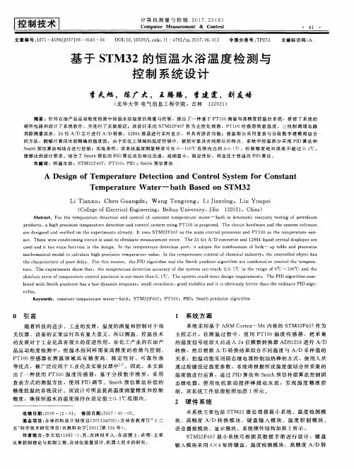
基于STM32单片机并网储能电池恒温控制系统设计近年来,新能源发电广泛并网,储能技术对于提高其电能质量与可靠性具有重要意义,进而成为电力系统的研究热点之一。
蓄电池组作为储能系统的主要设备,其寿命,容量和安全性均与温度紧密相关。
本文采用STM32单片机对并网蓄电池组的温度进行自动控制:温度采集,设定值设定,越值报警,制冷风扇与红外加热仪的控制。
用户通过人机交互界面DWIN-LCD工业串口屏界面设定阈值数值,预调整温度等数值,所有数据自动上传至上位机,通讯速率达到9600bps,系统可及时动作。
标签:储能;STM32单片机;人机交互界面;温度控制0 引言电池储能系统在电力系统中广泛应用,因其快速的对接入点的有功功率和无功功率进行调节,可用来提高电力系统的运行稳定性、提高供电质量,当其容量足够大时,甚至可以发挥电力调峰的作用[1]。
近些来,新能源并入电网,储能技术平抑波形,提高电能可靠性与参与二次调频的优势已经初步体现。
作为储能最核心的蓄电池组的作用更是不可忽视,其最佳工作温度为15℃至25℃,温度下降时,电池反应速率降低,输出功率也会下降;温度上升时,虽然输出功率会上升,但若温度过高,则会破坏电池内部化学平衡,导致材料的性能会退化和循环寿命缩短[2-3]。
但是我国北方冬天远低于15℃,南方夏天远高于25℃因此恒温控制系统对于维持蓄电池的使用寿命和输出功率至关重要。
1 硬件系统设计1.1 硬件需求列表蓄电池金属箱体1个;PLC模块1块;温度传感器1个;数码管2个;红外加热仪2个(1、2加热档各一个);制冷风机2个(1、2加热档各一个);蜂鸣器1个。
1.2 硬件结合方式硬件主体为蓄电池金属箱体。
在箱体内部将蓄电池架空安置,与红外加热仪及风机保持一定距离。
在箱体底部内测安装红外加热仪。
在箱体顶部外侧安装制冷风扇,采用分离装置,将风扇的叶片对准分离装置,以便冷风流通。
本设计的重点为当制冷风扇产生火花时,分离装置避免了蓄电池的明火引燃。
摘要当前快速成形(RP)技术领域,基于喷射技术的“新一代RP技术”已经取代基于激光技术的“传统的RP技术”成为了主流;快速制造的概念已经提出并得到了广泛地使用。
熔融沉积成型(FDM)就是当前使用最广泛的一种基于喷射技术的RP 技术。
本文主要对FDM温度控制系统进行了深入的分析和研究。
温度测控在食品卫生、医疗化工等工业领域具有广泛的应用。
随着传感器技术、微电子技术、单片机技术的不断发展,为智能温度测控系统测控功能的完善、测控精度的提高和抗干扰能力的增强等提供了条件。
本系统采用的STM32F103C8T6单片机是一高性能的32位机,具有丰富的硬件资源和非常强的抗干扰能力,特别适合构成智能测控仪表和工业测控系统。
本系统对STM32F103C8T6单片机硬件资源进行了开发,采用K型热敏电阻实现对温度信号的检测,充分利用单片机的硬件资源,以非常小的硬件投入,实现了对温度信号的精确检测与控制。
文中首先阐述了温度控制的必要性,温度是工业对象中的主要被控参数之一,在冶金、化工、机械、食品等各类工业中,广泛使用各种加热炉、烘箱、恒温箱等,它们均需对温度进行控制,成型室及喷头温度对成型件精度都有很大影响。
然后详细讲解了所设计的可控硅调功温度控制系统,系统采用STM32F103C8T6单片机作微控制器构建数字温度控制器,调节双向可控硅的导通角,控制电压波形,实现负载两端有效电压可变,以控制加热棒的加热功率,使温度保持在设定值。
系统主要包括:数据的采集,处理,输出,系统和上位机的通讯,人机交互部分。
该系统成本低,精度高,实现方便。
该系统加热器温度控制采用模糊PID控制。
模糊PID控制的采用能够在控制过程中根据预先设定好的控制规律不停地自动调整控制量以使被控系统朝着设定的平衡状态过渡。
关键词:熔融沉积成型(FDM);STM32;温度控制;TCA785AbstractIn the present field of Rapid Prototyping,the "New RP Technology" based on jetting technology is replacing the "Conventional RP Technology" based on laser technology as the mainstream of the Rapid Prototyping Technology.Fused Deposition Modeling(FDM) is the most popular Rapid Prototyping technology based on jetting technology.This paper mainly does research deeply on the temperature control system of FDM system.Temperature controlling is widely to food,sanitation,medical treatment,chemistry and industry.Along with the development of sensor technology,micro-electronics technology and singlechip technolog,brainpower temperature controlling system is perfected,precision of measurement and controlling is enhanced and the ability of anti-jamming is swelled.Singlechip STM32F103C8T6 in this paper is a high-powered 32-bit chip.It has plenty of hardware resource and strong ability foranti-jamming.It is specially suitable for making brainpower measurement instrumentand industry controlling system.The hardware resource of singlechip STM32F103C8T6 is fully exploited in this paper.The tool of temperature test is thermocouple of K style.This system realizes precise measurement and controlling of temperature signal with a little hardware resource.First,the need of temperature control is expounded.Temperature is a main controlparameter in industrial object.Various calefaction stoves,ovens and constant temperature boxes which all need control temperature are widely used in many industry such as metallurgy,chemistry,mechanism and foodstuff.Moulding room and spout temperatureawfully affect the precision of moulding pieces.Then the temperature control systemusing controllable silicon is explain in detail.This system adopts singlechip STM32F103C8T6 which acts as microcontroller.It can regulate the angle of double-direction controllable silicon and control voltage wave shape.So the virtual voltage of load can be changed and the calefaction power of calefaction stick can be controlled.Therefore the temperature canretain the enactment value.This system mainly consists of collection of data,disposal,output,communication of system and computer and communication of human and machine.This system has some advantages such as low cost,high precision andconvenience realization.This system adopts blury PID control.The adoption of blury PID control canceaselessly autoregulates basing initialized control rule,thus the controlled system willmove to the initialized balance state.Key words:Fused Deposition Modeling, STM32, temperature control, TCA785目录摘要.................................................................................................................................. Abstract (I)1 绪论 01.1 FDM工艺原理及应用 01.2 FDM国内外基本研究概况 (1)1.3 课题目的及意义 (2)2 温度控制系统方案分析 (4)2.1 温度控制的必要性 (4)2.2 温度控制系统的理论构成 (4)2.3 STM32和ADC (6)2.4温度控制系统的实现 (8)3 温度控制电路各部分的实现 (10)3.1温度检测电路 (10)3.2加热部分 (16)3.3键盘显示部分 (20)3.4软件部分 (20)3.5通讯总线的研究 (21)4 总结与展望 (23)4.1全文总结 (23)4.2研究展望 (23)致谢 (26)参考文献 (27)1 绪论1.1 FDM工艺原理及应用1.1.1 熔丝沉积技术原理早在十九世纪80年代末,美国学者Scott Crump博士第一次提出一种新的思想,该思想就是熔丝沉积技术的原型。
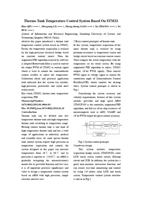
Thermo Tank Temperature Control System Based On STM32Biao QIU(····) , Shi-guang LI(····), Zheng-zhong GAO(····), Xu ZHANG(····), Yu RUI(····)(School of Information and Electrical Engineering, Shandong University of Science and Technology, Qingdao 266510, China)Abstract-this paper introduced a thermo tank temperature control system based on STM32, Firstly, the temperature acquisition is realized by the high-precision electrical bridge based on constant current source. Then the augmented PID algorithm realized by software is adopted Butterworth filter is used to convert the output PWM of STM32 to current signal which is used to control the semiconductor control rectifier to adjust the temperature. Calibration check and practical application both indicated that the system was reliable, high-precision, practicable and could meet reality needs.Key words-STM32; thermo tank; temperature acquisition; PIDManuscriptNumber:1674-8042(2011)01-0064-03Dio: 10.3969/j.issn.1674-8042.2011.01.161 introductionThermo tank can be divided into low temperature thermo tank and high temperature thermo tank according to temperature range. Heating control thermo tank is one kind of high temperature thermo tank and has a wide range of applications in industrial, medical and scientific areas. As some special thermo tank control system require high precision in temperature acquisition and control, the system designed in this paper can measure temperatures from 16℃to 80℃and its precision is superior to ±0.05℃. As ARM is gradually occupying the microelectronics market for its powerful function and low cost, it is of important practical significance and value to design a temperature control system based on ARM with high precision, simple structure and low cost. 2 Basic control principles of thermo tankIn this system, temperature acquisition of the inner thermo tank is realized by using platinum resistance as temperature sensor and bridge circuit based on constant current source. Then compare the actual temperature with the temperature set by touch screen. By using augmented PID algorithm to adjust, STM32 outputs 16-bit PWM signals. Then convert PWM signal to voltage signal to control the conduction angle of Semiconductor Control Rectifier(SCR) which controls the heating tubes. System control principle is shown in Fig.1.Considering the system accuracy and stability requirements, features of this system include: powerful and high speed ARM STM32F103 as the controller, augmented PID algorithm, and full use of on-chip resources of microcomputer such as ADC, USART and16-bit PWM output for great control accuracy.Fig 1 System control principle3 hardware designThis system includes temperature acquisition bridge circuit, STM32F103, color LCD touch screen control circuit, filtering circuit and SCR. In addition, the system has a good man-machine interaction function and can realize real-time monitoring and control by using 5.6 inches color LCD and touch screen. Temperature control system structure is shown in Fig.2.Fig 2 System structure3.1 temperature acquisition and A/D conversionAmong the thermal resistance temperature sensors, platinum resistance, with advantage as high precision, stable performance, corrosion resistance and easy to use, is the ideal temperature acquisition component widely used in industrial environments and control systems. As the temperature acquisition range is 16℃to 80℃, Pt1000 is chosen as temperature sensor, which resistance changes with temperature according to certain rules and has good high precision and stable performance.Unbalanced bridge measurement is typical in detect circuits using platinum resistance as temperature sensors[1]. However, the nonlinearity between platinum resistance and temperature and nonlinearity of unbalanced bridge lead to acquisition error, thus we improved the temperature acquisition bridge circuit. Use constant current source to power the bridge, connect the two bridge arms with precise operational amplifier that is low noise and low temperature drift, use 4DH2 to constitute constant current source circuit which outputs 0.5 A current, thus the current in platinum resistance is equal to constant current source.The ADC of STM32F103 is used to convert analog voltage of temperature into digital signal. The 12-bit ADC is a successive approximation analog-to-digital converter and has the function of self-calibration. D/D conversion of each channel can be performed in single, continuous, scan or discontinuous mode, and in this system we use continuous mode. The result of ADC is stored in right-aligned 16-bit data register which improves the conversion speed. In addition, the analog watchdog feature allows the application to detect if the input voltage goes outside the user-defined high or low thresholds.3.2 TM32F103 on-chip resourcesTM32F103 can work in -40℃~105℃and this meets the requirements of industrial environment. It incorporate the high performance ARM Cortex-M3 32-bits RISC core operating at a 72 MHz frequency, high speed embedded memories (Flash memory up to 128Kbytes and SRAM up to 20Kbytes) to store data and program, and an extensive range of enhanced I/Os, most of which have alternate functions and peripherals connected to two APB buses. It has three general purpose 16-bit timers plus two watchdogs, as well as standard and advanced communication interface USART used to communicate with LCD[2]. More importantly, it offers two 12-bit ADCs with 1μs conversion speed which make it suit for fast acquisition and fast processing. It is one of the important reasons for this system to choose TM32F103 as the core controller.3.3 Filtering and conversion circuitsIn order to realize the convention from PWM signal to analog output, we use the second order low pass filter to filter out the high frequency components and keep DC component and changing duty cycle of PWM signal so that the analog voltage output is got then. Fig.3 shows the designed Butterworth filter. After filtering, convert P WM signal to 0~2.5 V to control thyristor conduction angle[3]. Thus we realized the precise control of heating temperature.Fig 3 Butterworth filter4 Software design4.1PID control algorithmThis system uses PID control algorithm which is a basic control method widely used in industrial process control method widely used in industrial process control. Augmented PID control algorithm[4] isu k - u k- 1 = K P ( e k - e k- 1 ) + K 1 e k + K D ( e k - 2e k- 1 + e k- 2 ) .However, if this algorithm was used directly, it could generate a lare overshoot and cause integral saturation easily when starup, stop or adjust substantially. In order to inhibit the emergence of this phenomenon, we use integral separation as an improvement.Integral separation won't work until actual temperature is approaching the settings. When it works, it can eliminate static error and improve precision[5]. Block diagram of integral separation PID is shown in Fig.4.Fig 4 Integral separate PID algorithm block diagram4.2 Touch screen software designIt makes human-computer interface much more friendly, more convenient and faster by using touch screen. Use dedicated control chip ADS7843 to connect AMT9532, four-wire resistive touch screen, withSTM32F103, process the touch screen signals[6]. Touch screen's software design flow chart is shown in Fig.5.Fig 5 Touch screen flow chartUse standard thermometer with 0.001℃precision as calibration to check the experimental results. Specific methods: set different temperatures within the appropriate range though touch screen, wait until the temperatures shown in the LCD are stable, then calculate the errors based on the actual temperature of standard thermometer with formula:Error=|set-actual|/set.The check results are shown in Tab.1.Tab.1 Calibration results6 conclusionBy using 16-bit PWM output, simple filtering circuit conversion circuit, software design and floating-point operations, this system realized 16-bit D/A. Conversion which is very hard for common MCU to realize.The system temperature range is 6℃~80℃and the resolution of 16-bit control signal could reach to 10‰. The experimentalresults show that the system definitely can reach the control requirement that temperature accuracy is better than ±0.05℃. The application shows that this system has the real-time, flexible, stable high-precision, and low cost advantages, and can meet the industrial requirements of high accuracy, high stability and reliability.References[1] Zhaojun Li, Ping Ji, Xiangguang Lou, 2007, Design of high precision temperature control system. Electronic Measurement Technology. (2): 146-148.[2] ST Microelectronics Corporation, 2007. STM32F103XX Data sheet.[3] Dayong Xia, Xiaohui Zhou, Zeng Zhao, Bofeng Chen, Endian Hu,2007. Temperature control system of single-chip of model MCS-51. Industrial Instrumentation & Automation, (1):43-47.[4] Lin Wu, Enping Lou, Dongqing Hou, Liang Xu, 2006, Wireless temperature and humidity control system based on PID arithmetic. Chinese Journal of Scientific Instrument, 27(21):619-620.[5] Yan Zhao, Guangzhi Yang, 2006. Automatic measuring system in constant temperature for oxygen content based on singlechip. Chinese Journal of Scientific Instrument, s1.[6] Songmei Zhang, Junkai Liang, Longji Liu, 2008. Deign of thermo tank temperature control system based on C8051F. Electronic Measurement Technology, 31(9): 147-149.基于STM32的恒温箱温度控制系统摘要—这篇文章介绍了一个基于STM32的恒温箱温度控制系统,首先,由基于常流源的高精度电桥获取温度,然后,由软件实现的扩充型PID算法在这里得到应用,使用巴特沃兹滤波器(最平坦滤波器)将STM32输出的PWM转换成电流信号来控制半导体整流器从而调节温度,校准检测和实际应用都表明这个系统可靠、精度高、可行性好,并且能够满足现实需要。
![基于STM32F103T6的温度控制系统设计[权威精品]](https://uimg.taocdn.com/1f6f9ceac8d376eeaeaa3174.webp)
基于STM32F103T6的温度控制系统设计摘要:针对目前温度控制在工业生产中被广泛应用,而传统的温度控制系统是由功能繁杂的大量分离器件构成,为了节约成本、提高系统的可靠性,本文设计了一种基于STM32F103T6的温度控制系统。
在该系统中,为了减小干扰的影响,用低通数字滤波算法对采样数据进行处理,然后用PID 算法进行决策输出。
同时,利用CAN总线和其他节点进行数据交换。
经过测试,该系统的技术指标满足要求,运行稳定可靠。
Abstract: Specially the temperature control systems are extensively used at present, while the traditional temperature control systems consist of abundant discrete devices. In order to lower the cost and improve the system reliability, the temperature control system based on STM32F103T6 is introduced in the paper. In the system, the sample data are deal with low-pass digital filtering algorithm to decrease the disturbance, and then the output is deduced with the PID algorithm. At the same time, the controller can exchange data with the other nodal points by CAN bus. It is proved that the technical index of the system is satisfied and it works steady.关键词:温度控制;低通数字滤波;PID算法;CAN总线Key words: temperature control;low-pass digital filtering algorithm;PID algorithm;CAN bus TP273 A 1006-4311(2013)28-0240-020 引言在工业控制系统中,温度是最主要的被控参数之一。
stm32单片机温控电路设计概述说明以及解释1. 引言1.1 概述在现代工业和生活中,温控电路设计是一个非常关键的技术领域。
通过对温度的监测和控制,可以实现许多重要的功能,例如保持设备运行在适宜的温度范围内,提高工作效率,预防过热或过冷导致的故障等。
而STM32单片机则是一种广泛应用于嵌入式系统中的强大的微控制器芯片,在温控电路设计中发挥着重要作用。
1.2 文章结构本文主要分为以下几个部分进行阐述。
首先介绍STM32单片机以及其在嵌入式系统中的作用与优势。
然后详细讲解温控电路设计原理,包括基本原理、主要组成部分等内容。
接着会对温度传感器进行选型与接口设计方面进行深入探讨。
最后,我们将进一步展开讨论其他相关话题并得出结论与展望。
1.3 目的本文旨在通过对STM32单片机温控电路设计的概述说明和解释,帮助读者更好地理解和应用该技术。
同时,将介绍一些常见的温控电路设计原理和方法,以及如何选择适合的温度传感器并设计有效的接口。
通过本文的阅读,相信读者能够对STM32单片机温控电路设计有更深入的了解,并且能够根据实际需求进行具体应用。
2. 正文:2.1 stm32单片机简介STM32单片机是由STMicroelectronics(意法半导体)公司开发的基于ARM Cortex-M内核的微控制器系列。
它具有强大的性能、高度集成的外设以及丰富的接口,广泛应用于各种嵌入式系统中。
2.2 温控电路设计原理温控电路设计的目标是通过对温度进行监测和反馈调节,实现对某个系统或器件的温度进行精确控制。
其原理可以简要分为两个步骤:温度检测和温度调节。
在温度检测方面,我们通常会选用一种合适的温度传感器来实时感知环境或器件中的温度变化。
传感器将通过电压信号、模拟信号或数字信号等形式输出相应的温度数值。
而在温度调节方面,我们使用stm32单片机作为控制器来完成。
借助stm32单片机丰富的外设和强大的处理能力,可以通过与其他元件(如继电器、加热元件等)结合使用,在有效范围内调整或维持系统、器件所需的目标温度。

基于STM32的温湿度检测系统设计及实现一、本文概述本文旨在探讨基于STM32的温湿度检测系统的设计与实现。
我们将详细介绍整个系统的硬件组成、软件设计以及实现方法,并通过实验验证其性能和可靠性。
我们将概述STM32微控制器的特点和优势,以及为什么选择它作为温湿度检测系统的核心。
然后,我们将详细介绍系统的硬件设计,包括温湿度传感器的选择、电路设计和搭建等。
接下来,我们将阐述软件设计思路,包括传感器数据的读取、处理、显示以及传输等关键问题的解决方案。
我们将通过实验数据来验证系统的性能和可靠性,并讨论可能存在的改进和优化方案。
通过本文的阐述,读者可以对基于STM32的温湿度检测系统有一个全面而深入的了解,为相关研究和应用提供参考和借鉴。
二、系统总体设计本设计旨在开发一个基于STM32的温湿度检测系统,该系统能够实现环境温湿度的实时监测,并将数据通过适当的接口进行传输,以便进行后续的数据处理和分析。
设计目标包括高精度测量、低功耗运行、良好的用户界面以及易于扩展和集成。
系统的硬件架构主要由STM32微控制器、温湿度传感器、电源管理模块、通信接口以及显示模块组成。
STM32微控制器作为核心处理器,负责数据的采集、处理和控制逻辑的实现。
温湿度传感器用于实时采集环境中的温度和湿度信息。
电源管理模块负责为系统提供稳定的电源供应,保证系统的稳定运行。
通信接口用于将采集到的数据传输到外部设备或网络,实现远程监控和数据分析。
显示模块则提供用户友好的界面,展示当前的温湿度信息。
软件架构的设计主要包括操作系统选择、任务划分、数据处理流程以及通信协议等方面。
考虑到STM32的性能和功耗要求,我们选择使用嵌入式实时操作系统(RTOS)进行任务管理和调度。
任务划分上,我们将系统划分为数据采集任务、数据处理任务、通信任务和显示任务等,确保各个任务之间的独立性和实时性。
数据处理流程上,我们采用中断驱动的方式,当传感器数据采集完成后,通过中断触发数据处理任务,确保数据的及时处理。
2019.32科学技术创新基于STM32F407的温度控制系统王艳1张平1王莉2(1、潍坊理工学院,山东潍坊2625002、青岛科技大学,山东青岛266061)1概述随着智能化时代的到来,温度控制系统的应用也逐渐趋向于智能化。
温度控制应用于生活生产中的方方面面,尤其是某些对生产环境要求较高的工业,实现温度控制智能化将会大大节约人力资源,降低社会消耗,因此,实现温度控制在未来将变得越来越重要。
本文使用STM32F407单片机建立了一套比较完整可行的温度控制系统,实现了对温度的控制,尤其是在温度恒定方面。
经过检验,本方案切实可行,结果合理可靠。
2方案介绍本方案分为六个模块:电源模块、按键模块、显示模块、信号处理模块(包含ADC 采集功能)、单片机控制模块、功率输出模块。
下图是整个方案的介绍:系统通过驱动电路对水泥电阻进行加热,在加热过程中,温度传感器DS18B20感知水泥电阻的实时温度,并输出自身的电压值,根据电源模块提供的电压,得到热敏电阻的电流值,进而由电阻值使用二分法查表计算出水泥电阻的温度。
将采集到的温度与目标温度进行比较,如果目标温度高于采集温度,则对驱动电路继续输出PWM ;如果目标温度低于采集温度,则停止加热。
同时本系统使用了PID 算法对PWM 输出进行精确的控制,从而可以调节温度的加热速率,维持目标温度稳定。
3单片机系统硬件设计3.1单片机在本方案中,STM32F407单片机是实现温度控制的核心部分。
它能够方便对温度传感器采集回来的数字信号进行处理。
它还可以进行低功耗、低电压的操作,并且具有高效性、实时性,同时拥有一个完全集成和易于编程的开发环境。
经过比对,发现F407的处理速度明显比F103快,所以最终选取了STM32F407单片机。
3.2按键模块和显示模块本方案使用了按键模块和显示模块。
通过四个按键的加减实现目标温度的设定和加热速率的调节;配合显示屏模块显示目标温度、加热速率曲线以及当前温度。
2017拄 第5期 仪表技术与传感器
Instrument Technique and Sensor 2017
No.5
基于STM32的高精度恒温控制系统设计 黄琦 ,韩广源 ,吴瑞东 ,刘 毅 ,杨世强 ,张明江。.-,张建忠 , (1.太原理工大学新型传感器与智能控制教育部与山西省重点实验室,山西太原030024; 2.太原理工大学物理与光电工程学院,光电工程研究所,山西太原030024;3.太原世诺科技有限责任公司,山西太原030024)
摘要:针对分布式光纤拉曼测温系统中定标光纤和雪崩光电二极管(APD)的温控要求,设计了一 套基于STM32的高精度恒温控制系统。系统采用上下位机结构.上位机负责设定温度值和显示温度数 据,下位机根据上位机的设定值利用PID算法对恒温箱的温度进行控制。实验结果表明:在22℃的室 温下,定标光纤温度稳定在(10+0.1)℃,APD温度稳定在(5 ̄0.005)oC,上位机可准确反映温度的数值 和变化趋势。整套恒温系统能够满足分布式光纤拉曼测温系统的温控要求。 关键词:STM32;高精度;温度;STemwin;PID算法 中图分类号:TP273 文献标识码:A 文章编号:1002—1841(2017)05—0071-04
Design of High-precious Constant Temperature Control System Based on STM32 HUANG Qi ,HAN Guang—yuan ,WU Rui—dong ,LIU Yi ,YANG Shi—qiang , ZHANG Ming-jiang .ZHANG Jian—zhong ’ (1.Key Laboratory of Advanced Transducers and Intelligent Control System,Ministry of Education and Shanxi Province, Taiyuan University of Technology,Taiyuan 030024,China; 2.College of Physics and Optoelectronics,Institute of Optoelectronic Engineering,Taiyuan University of Technology, Taiyuan 030024,China; 3.Taiyuan Shi Nuo Technology Limited Liability Company,Taiyuan 030024,China)
Abstract:Aiming at the temperature requirements of the calibrating fiber and avalanche photo diode(APD)in distributed optical fiber Raman temperature sensing system,a constant temperature control system with high precision was designed based on STM32.This system adopted upper aM lower computers.The upper computer can set the temperature value and display tempera・ ture,meanwhile,the lower computer can control the incubator temperature with the PID algorithm according to the instruction from the upper computer.The experiment results show that the calibrating fiber and the APD can stabilize at(10 ̄0.1)℃and(5± 0.005)oC at loom temperature of 22 oC.respectively,Besides,the upper computer can accurately reflect the temperature value and its variation trend.It is reasonably believed that the complete set of thermostatic device can meet the temperature demands in distributed optical fiber Raman temperature sensing system. Keywords:STM32;high precision;temperature;STemwin;PID algorithm
0引言 分布式光纤拉曼测温系统是利用后向拉曼散射 光的温度效应进行温度探测的新型传感系统…。系 统以光纤作为传输和传感介质,相对其他的测温方法 具有抗电磁干扰、测量距离长、本质安全等优点,已广 泛应用在油气管道、隧道等领域l2 ]。 在分布式光纤拉曼测温系统中,各器件的参数受 基金项目:国家自然科学基金面上项目(61377089);山西省科 技攻关项目(20140321003—1);山西省高等学校优秀青年学术 带头人支持计划(20121fjyt08);山西省煤基重点科技攻关项目 (MQ2014-09);山西省煤层气联合研究基金资助项目 (2015012005) 收稿日期:2016-07-09 环境温度的影响极易发生改变,严重影响系统的稳定 性和测温准确性.其中定标光纤和APD尤为突 出[2l4 ],故需对两者进行必要的温度控制。常见恒温 箱的温控误差在±0.1℃左右,且仅可对单点的温度进 行反馈控制.无法达到很好的控温精度和温度均匀 性。本文提出了一种基于STM32的温度控制系统,通 过上下位机分工协作,实现了高精度均匀控温,同时 可通过上位机设定所需的温度及查看当前的温度值, 保证了分布式光纤拉曼测温系统的测温精度。 1恒温系统的硬件设计 整个恒温系统如图1所示,主要由上位机电路、下 位机电路和电源管理部分组成。上位机电路实时显 72 Instrument Technique and Sensor May.2017 示下位机传输的数据并绘制成不断更新的曲线,可对 历史数据进行保存并通过USB传输到电脑端进行后 续处理。下位机电路主要根据上位机设定的温度值, 并通过温度传感器测得的温度值不断调整制冷片和 散热模块的功率,实现对温度的闭环控制。电源管理 部分主要对上位机电路和下位机电路进行供电。 电源管理卜_] ,{珊H温黩感lT 位一 — 下—] 位 机r——————J l l L————] 机 rJl-——]r— L—]电 晕吾f数据传输l I数据存储f 散热 II制冷片l路 l 模块 l l 模块 l l 模块l l驱动模块I 图1系统总体结构图 1.1上位机硬件设计 为实现较好的人机交互,上位机主控选用32位 STM32F407IGT6微控制器。此芯片基于高性能的 ARM Codex—M4 RSIC内核 J,时钟频率168 MHz.包 含1 M字节的Flash.192 K字节的SRAM.另有可变静 态存储控制器(FSMC)和USB 2.0全速device控制器 以及安全数字输入输出(SDIO)和控制器局域网络 (CAN)总线,能够满足上位机的设计要求。 上位机电路主要由人机交互模块、数据传输模块 和数据存储模块组成,其控制原理如图2所示。人机 交互模块选用7”TFT屏完成显示和触摸操作(1”= 2.54 cm),控制器为RA8875,其最大支持800x480点 分辨率且集成触摸控制器。RA8875通过sTM32F407 的FSMC控制器驱动可在TFT屏上显示温度的数值 和变化趋势,并可根据用户的触摸操作执行特定的指 令。数据传输模块包含与下位机的数据传输和与PC 端的数据传输,前者选用高可靠性的CAN总线通信, CAN收发芯片选用SN65HVD230:后者通过全速 USB2.0控制器实现PC端对内存卡中数据的读写。 数据存储模块包含2 M字节的外部高速SRAM (IS61WV102416BLL)用于对温度数据的缓存,2 G字 节的Micro SD卡用于历史数据的长期保存。 囤< 回㈤ 固< 图2上位机控制原理图 1.2下位机硬件设计 下位机电路主要实现对恒温箱具体的温度控制。 如图3所示。同样选用硬件资源丰富的 STM32F407IGT6微控制器作为主控芯片_8],其具有l7 个定时器,140个具备中断功能的I/O口,3个串行外 设接口(SPI)且可通过编程将普通I/O口复用为集成 电路(IIC)接口,能够满足下位机的控制要求。 TBC3 ADT74lO A ADT7410 B 。r iver3 D q _户q _p
PIM PD1; 嚣 蹩uo.
c,1 ̄ ̄ PA 9 蹴糍瓤咖
誊萋重量
5 ] l 薹 虿
两 司 I ∞ 星
罾 l CNAOlJT TXD I L'{面
GNDCANHH CANL I VCC CANLH CANHl RXD I r_15V I
G3.N3VD I3.3v P。wer
图3下位机控制原理图 分布式光纤拉曼测温系统的恒温箱采用内外2层 的结构,外层放置定标光纤,内层放置APD,故温度传 感模块分为两部分。外层恒温室空间较大,为实现较 好的温度均匀性,在其底部和顶部分别放置了温度传 感器A,B;而内层恒温室空间较小且通过铜块导热, 故只放置了1个温度传感器C。由于定标光纤设计的 控温误差为±0.1℃,故温度传感器A。B均选用l6位 高精度数字温度传感器ADT7410。其在一40~105 oC范 围内的温度精度为±0.5℃,温度分辨率为0.0078 oC, 采用IIC接口与主控进行通信,简单易用。APD设计 的控温误差为±0.005 oC.而集成温度传感器的温度分 辨率普遍在0.01 oC左右。故温度传感器C选用线性 NTC温度传感器配合高精度模数转换器进行温度测 量。其中线性NTC温度传感器的温度系数为 2 mV/℃,模数转化芯片选用24模数转换器AD7793。 AD7793内置一个低噪声、带有3个差分模拟输入的 ADC,最高23位有效分辨率且内置高精度基准电压, 配合线性NTC温度传感器可以实现0.0005 oC的分 辨率。 恒温箱的温度通过半导体制冷片(TEC)进行控 制,TEC利用半导体材料的珀尔贴效应制成.具有体 积小、精度高、响应速度快等特点[9].在小型温度控制 系统中具有广泛的应用。为保证恒温室的制冷效率