窗控制系统
- 格式:doc
- 大小:213.00 KB
- 文档页数:6
智能家居中的智能化窗户控制技术研究随着人们对生活品质要求的不断提高,智能家居系统变得越来越普及,成为了生活中必不可少的一部分。
而智能家居系统中的智能化窗户控制技术,作为家庭安全和舒适度的重要保障,也越来越受到人们的关注和重视。
一、智能化窗户控制技术的意义智能化窗户控制技术是指利用智能技术,使窗户具有自动、智能、节能等功能,从而实现对室内环境的智能调节和控制。
智能化窗户控制技术不仅可以提高居住环境的舒适度,还可以有效地节约能源,降低能源消耗,环保节能的理念得到了体现。
智能化窗户控制技术的开发和应用,不仅可以带来贴心的智能化家居体验,还可以强化房屋安全的保障。
二、智能化窗户控制技术的开发现状目前,智能化窗户控制技术的开发已经成为人们关注的热点。
各大企业和科技公司纷纷投入研究推广智能化窗户控制技术。
目前主要的智能化窗户控制技术包括人体靠近感应开窗器、智能感应窗帘、人机交互式智能电动窗等。
这些技术不仅实现了窗户的自动化控制,还提供更加智能化便利的家居体验。
三、智能化窗户控制技术的应用场景智能化窗户控制技术主要应用于各类型住宅和商业建筑物,还可以应用于工业以及各类大型控制系统。
比如,在办公室、酒店客房、班级、电影院等场所,都可以利用智能化窗户控制技术实现一键开关、调节室内温度等控制,让使用者可以自由调节被动态的室内环境。
这种技术还可以用在野外房屋,利用智能控制系统,及时控制窗户的开关,以自然通风为主,保持透气、耐寒、节能、清洗、保护等功能。
四、智能化窗户控制技术的优劣势智能化窗户控制技术的优势主要体现在以下几个方面:1.节能环保:采用高效节能的技术,可以让窗户自动控制,减少能源浪费和环境污染。
2.安全可靠:在窗户上安装智能化控件,可以实现远程监控、自动报警和门锁强化等功能,极大地保障房屋的安全。
3.贴心舒适:利用智能技术,以及窗户的视觉和天气感应装置,使窗户在满足功能的同时,带来更加贴心的、舒适的使用体验。


智能家居智能窗户的技术要求智能家居智能窗户的技术要求随着人们对居住环境舒适度要求的提高以及科技的不断发展,智能家居已经成为了现代家庭的主流趋势。
在众多智能家居设备中,智能窗户作为一个非常重要的组成部分,不仅可以提供便利的控制方式,还能够有效地节约能源,提高居住环境的舒适程度。
智能窗户的技术要求主要包括以下几个方面:1. 智能控制系统:智能窗户需要具备智能控制系统,可以通过网络或APP实现与手机或其他智能设备的连接和控制。
这样,用户就能够远程控制窗户的开启、关闭、升降和调光等功能,实现对室内温度、光线等环境参数的精确调节。
同时,智能控制系统还需要具备智能学习和自适应功能,能够根据用户的习惯和喜好自动调节窗户的开启程度,提高用户的使用便利性和体验。
2. 智能感应技术:智能窗户需要能够感知室内和室外环境的变化,根据环境参数的变化实时调整窗户的开启程度和调光效果。
其中,室内环境的感应主要包括温度、湿度和二氧化碳浓度等参数的感应,室外环境的感应则主要包括天气、光照等参数的感应。
通过智能感应技术,智能窗户可以根据室内室外环境的变化自动开启或关闭,提供更加舒适的居住环境。
3. 节能设计:智能窗户需要采用节能设计,实现对室内能源的有效利用和节约。
例如,智能窗户可以通过外界光照的感应自动调整透光度,减少室内的照明需求,从而节约能源。
此外,智能窗户还可以根据室内温度的变化自动开启或关闭,实现室内空气的自然通风和降温,减少空调的使用频率。
4. 高效隔音和防紫外线功能:智能窗户需要具备高效的隔音和防紫外线功能,有效降低室内噪音和紫外线的侵入。
通过采用高效的隔音材料和技术,智能窗户可以实现对外界噪音的有效屏蔽,提供安静的居住环境。
同时,智能窗户还需要采用优质的防紫外线材料,可以有效阻挡紫外线的侵入,保护室内家具和人体皮肤免受紫外线的伤害。
5. 安全性能:智能窗户需要具备良好的安全性能,确保用户的安全和隐私。
这包括窗户的抗风、抗震能力,以及防火和防盗等功能。
自己做一键升窗原理
一键升窗是车窗控制系统中的一种功能,它能够通过按下一键按钮来自动将车窗关闭或打开到特定位置。
下面为您介绍一键升窗的原理。
1. 控制单元:一键升窗的控制单元通常位于车辆的中央控制面板或者驾驶员门上的控制面板上。
控制单元主要负责接收来自按钮的信号,并根据信号激活相应的窗户电机。
2. 按钮:一键升窗系统通常只有两个按钮,一个用于将窗户上升,另一个用于将窗户下降。
当按钮被按下时,它们会通过导线传输信号到控制单元。
3. 电源:一键升窗系统需要电源来供电。
通常情况下,车辆的电池会为此提供电源。
4. 窗户电机:每个车窗都配备了一个电动马达或电机来控制窗户的升降。
这些电机通常位于车窗下方的门内。
工作原理如下:
- 当按下“升上”按钮时,按钮会发送一个电信号到控制单元。
控制单元接收到信号后,它会激活窗户电机来将窗户升高到设定的位置或者完全关闭。
- 当按下“下降”按钮时,按钮会发送另一个电信号到控制单元。
控制单元根据信号激活窗户电机来将窗户下降到设定的位置。
- 控制单元与窗户电机之间通过电线进行连接。
控制单元会向电机发送指令来控制其运行。
当窗户到达设定位置时,控制单元会发送停止信号给窗户电机,以停止其继续运动。
总之,一键升窗通过控制单元、按钮、电源和窗户电机的协作来实现对车窗的自动升降控制。
这种系统不仅提供了便捷性和舒适性,还增加了汽车的智能化程度。

矿用调节风门(风窗)远程智能自动控制系统简介远程自动调节风门或煤矿远程自动调节风窗系统控制、矿用调节风门(风窗)远程智能自动控制系统在远程自动调节风门或远程自动平衡风门上位机界面的右侧有急停按钮、复位按钮、开门按钮、关门按钮解锁按钮、互锁按钮,百叶窗旋转角度输入窗口、百叶窗控制按钮等,通过点击各控制按钮达到需要的风门运行状态。
为了安全起见,急停按钮使用谁安急停按钮谁具有复位的权利,即井下现场人员使用了急停按钮停止了正在运行的风门,则只有井下现场的人员再次按下现场的急停按钮,风门才复位(恢复到初始的状态),反之远程使用急停按钮功能时也同理。
井上管理员可以根据设定的风速传感器参数是否在正常范围区域内而通过改变百叶窗的旋转角度来调整百叶窗或推拉式调节风窗的通风横截面的大小,进而达到理想的情况。
现场通风部门的人员也可以根据相关仪器测得的参数和要求标准在与井上管理员沟通后,通过现场的电控按钮控制百叶窗的旋转角度,达到满足正常的通风要求。
远程上位机上的解锁按钮可以实现两道风门之间解除互锁的状态,为大型设备的通行和出现突发事故时矿工快速撤离到安全区域提供了条件。
矿用调节风门(风窗)远程智能自动控制系统本系统采用RJ45标准通讯接口,执行TCP_Modbus通讯协议标准,具有2路通讯接口,采用单模双纤模式传送信号至地面控制中心,主要有以下几项功能。
1.1管理权限:1.1.1本系统采用RBAC理论分为三级管理模式;一级管理人员具有查看、修改参数、控制风门的运行的权限,并对二级、三级管理人员的账户进行管理(包括登记、删除),二级管理员可以查看、控制风门的运行;三级管理员只能查看风门的运行状态、各传感器的数据参数、视频等;1.1.2厂家管理员具有恢复出厂设置的功能;降低了因一级管理员非正常离职给后续矿方管理人员带来的工作难度。
1.2不同风门界面的切换:把上位机界面切换到需要查看的风门界面有两种不同的方法。
根据客户的巷道图纸在本系统内创建矿井巷道电子地图,风门地理位置标示清晰,在主界面上方点击“分布点设置”进入巷道电子地图,然后点击需要切换到的风门代号实现一键链接,直接将上位机界面切换到相应的风门主界面。
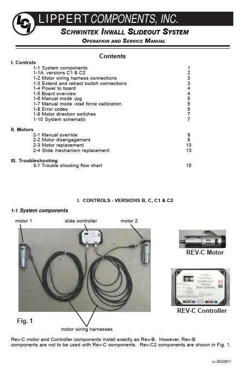
PERATION AND ERVICE ANUALContentsI. Controls1-1 System components 11-1A versions C1 & C221-2 Motor wiring harness connections31-3 Extend and retract switch connections 31-4 Power to board 41-5 Board overview 41-6 Manual mode -jog51-7 Manual mode -stall force calibration 51-8 Error codes51-9 Motor direction switches 71-10 System schematic 7II. Motors2-1 Manual override82-2 Motor disengagement 82-3 Motor replacement102-4 Slide mechanism replacement 13III. Troubleshooting3-1 Trouble shooting flow chart15I. CONTROLS - VERSIONS B, C, C1 & C21-1 System componentsmotor 1 slide controller motor 2motor wiring harnessesRev-C motor and Controller components install exactly as Rev-B. However, Rev-Bcomponents are not to be used with Rev-C components. Rev-C2 components are shown in Fig. 1.REV-C MotorREV-C ControllerFig. 1REV E0309111-1A CONTROLLER VERSIONS C1 & C2New control configurations for version C1 & C2, see below:1-1A.1 CONFIGURATION1. Press button 2x and hold 3rd for 5 seconds to enter manual mode.2. Press button 4x and hold 5th for 5 seconds to enter stall threshold calibration mode.3. Press button 6x and hold 7th for 5 seconds to Override mode.1-1A.2 MANUAL MODE1. Green Led blinks once, wall switch controls motor 1.2. Press button, Green Led blinks twice, wall switch controls motor 2.3. Press button, Green Led solid, wall switch controls motor 1 and 2.4. Press and hold button to exit.1-1A.3 STALL THRESHOLD CALIBRATION MODE 1. Use Pot to turn stall threshold up/down.2. Press button to save and exit.1-1A.4 OVERRIDE MODE1. Use the extend/retract switch to move both motors in/out all pulse counting, and stall are disabled in this mode.2. Over-current and short circuit detection are still active to help prevent damage to the board.3. To exit the mode, push and hold the push button switch until the LEDs begin to blink simultaneously.Exiting the override mode resets the motor positions.I. CONTROLS - VERSIONS C1 & C2Version C1 maintains the same motor harness connector to the controller as in version C. However, the connector at the motor has been insulated with a new molded shield to protect against external damage.Version C2 motor harnesses have molex connectors at the controller and themolded connector at the motor end.Wire colors match with color codes on control board.NOTE: It doesn’t matter which motor is 1or 2.21-2 Motor wiring harness connectionsNOTE: Ribs on motor connector line up with notch in side of male connector on wiring harness.Color codes on wires also match (black to black, red to red, etc.).1-3 Extend and retract switch connections NOTE: Direction control switch (customer supplied)Common connection on control board goes to common connection on extend and retract switch.The extend and retract connections on the control board go to the extend and retract terminals on the switch. Power is supplied to switch from any nearby 12VDC power source.3Correctly connected motor1-4 Power to board¼ spade terminals are provided for power into the board. (Voltage range 8vdc to 18vdc).12 vdc is recommended. Lower voltages reduce available power to room slide. 10ga wire is the minimum size recommended.1-5 Board overviewStatus led’s - 2 led’s, 1 green and 1 red, are provided to indicate current controller status and faults.Motor direction switches - Used to change direction of motors, 2 are provided, 1 for each motor.Mode button - Places controller in manual mode, for jogging individual motors. Places controller in calibration mode, where stall current can be increased or decreased or returns controller to auto mode.Power source - 12 volt dc input. Unit will operate from 8 volts dc to 18 volts dc.Motor 1 connector - Power and encoder input for motor 1.Direction switch connector - Provides input from customer supplied extend and retract switch.Stall calibration - Allows for adjustment of stall force.Motor 2 connector - Power and encoder input for motor 2.1-6 Manual mode -JogPress mode button 2 times quickly, press a 3rd time and hold for approximately 5 seconds. The green led will flash on and off. Manual mode now active for motor #1. Using the extend and retract switch, motor 1 can be jogged manually.Press the mode button 1 more time and the green led will flash on and off. Manual mode is now switched to motor #2. The extend and retract switch will now jog motor #2.When both motors have been jogged to the desired position, exit manual mode by pressing and holding the mode button until both red and green led’s start to flash. The control is now back in auto mode.1-6. 2 Units with the C1 board “electronic” manual override.In the event of any fault code , the unit can be manually overridden electronically using these steps:1. Locate the circuit board2. Press the “mode button” six times quickly, press a 7th time and hold for approximately 5 seconds.3. The red and green LED lights will begin to flash indicating you are in override mode4. Using the wall switch, press and hold the “in” button until the unit comes completely in.status led’s motor direction switches mode button power connectionmotor 1 connector motor 2 connector direction switch stall calibration 41-7 Stall force calibrationIf the system stalls out before reaching end of stroke, or if the room doesn’t seal as tightly as desired, then stall force may be increased.***CAUTION***IF ROOM STALLS MID STROKE, MAKE SURE THAT THERE ARE NO OBJECTS IN THE WAY,OR THAT SOMETHING HAS BEEN PULLED INTO THE SYSTEM, CAUSING RESTRICTED MOVEMENT. ALSO CHECK SYSTEM VOLTAGE. EVEN THOUGH THE SYSTEM CAN RUN ON AS LITTLE AS 8VDC, THE FORCE AVAILABLE TO MOVE THE ROOM IS REDUCED ON LOWER VOLTAGE. IF THE ROOM IS FREE OF OBSTRUCTIONS AND VOLTAGE IS SUFFICIENT(12VDC) AND THE SYSTEM STILL STALLS MID STROKE, ONLY THEN SHOULD STALL FORCE BE INCREASED.Press mode button 4 times quickly, then press a 5th time and hold for approximately 5 seconds.The red led will start to flash, flash, flash, … Break the seal on the cover over the stall force calibration hole. Directly below the sealed hole is a potentiometer. Using a small screwdriverincrease the stall force by turning clockwise, turning counter-clockwise will reduce stall force. Once the desired setting has been reached press the mode button and both led’s will light up. The board is now back in auto mode.It is desirable to increase the stall force only enough to insure proper functioning of the room.Increasing the setting beyond the amount needed only shortens system life.51-8 Error codesDuring operation when an error occurs the board will use the led’s to indicate where the problem exists.For motor specific faults the green led will blink 1 time for motor 1, and 2 times for motor 2. The red led will blink from 2 to 9 times depending on the error code.The error codes are as follows:2Battery drop out: Battery capacity low enough to drop below 6 volts while running 3Low battery: Voltage below 8 volts at start of cycle 4High battery: Voltage greater than 18 volts 5Excessive motor current: High amperage, also indicated by 1 side of slide continually stalling.6Motor short circuit: Motor or wiring to motor has shorted out.8Hall signal not present: Encoder is not providing a signal. Usually a wiring problem.9Hall power short to ground: Power to encoder has been shorted to ground. Usually a wiring problem.When an error code is present, the board needs to be re-set. Energizing the extend/retract switch resets the board. Energize the extend/retract switch again for normal operation.1-9 Motor direction switchesred led green led mode switchmotor direction switches Motor direction switches are used to change the direction of individual motors. If when trying to extendor retract the room, one side goes in and the other side goes out, then there is a problem in the wiring.The motor direction switches can be used to correct this problem. The left switch controls motor 2 and the right switch controls motor 1. If motor 1 is going in the wrong direction then change switch 1’s position. If motor 2 is going in the wrong direction then change switch 2’s position.The motor direction switches can also be used to change the direction of the extend/retract switch. If the room extends when the extend/retract switch is moved to the retract position, it’s direction can be reversed by moving both switch 1 and switch 2 to their opposite positions. This feature can be used if it is more convenient to change the motor direction switches than to rewire the extend/retract switch.6II. Motors2-1 Motor disengagementIf motors need to be disengaged, follow these steps:1. On the outside of the room, approximately 2 inches above the top guide rack there is a motor retention screw. Remove this screw.2. Directly above the rack, pull back the weather stripping to expose the bottom of motor. Insert ascrewdriver between the motor and it’s mount and pry the motor up.1-10 System schematic Revisions B - C - C1730A10 G A . W I R E M I N .1-11System schematic Revisions C281GA.WIREMIN.TO12VDCSOURCE2SPADETERMINALCONNECTION*************Do not move the rv with the motors disengaged.*************5. If the rv needs to be moved, a travel lock will need to be made as follows: With the room closed, cut a board 1 inch longer in length than the distance between the interior stop and the wall. Wedge this board tightly between the wall and stop to lock 1 side of the room. Cut another board to fit the other side of the room and wedge into place. This should lock the room in the retracted position, allowing the rv to be moved.Alternately several ratchet straps may be used,wrapping completely around the rv, and room,then pulled tight. Depending on the size of the room, straps with a 500 to 1000 pound capacitywill be required.**********Do not move the rv unless the motors are plugged in.*************93. Lift the motor approximately 1 inch, tighten the motor retention screw to hold the motor in it’s raised position.4. The motor is now disengaged. Repeat these steps on the other side of the room. The room should move freely, and can be pushed in or out as desired.102-2 Motor replacement1. If a motor needs replacement follow steps 1 through 4 for motordisengagement.2. With the motor disengaged place support under the room. Wedges, a jack, or forklift may be used.3. Once the room is supported, remove the screws retaining the side column to the outside face of the rv.4. Slightly raise the room to remove any weight from the side column. It is now possible to slide the side column out of the wall, it may be necessary to use a pry bar to start the column moving. Slide the column out until it is past the outside face of the wall.5. Remove the motor retention screw and lift the motor out the top of the side column.6. There is a coupler, which connects the motor to the drive mechanism. If the coupler is still attached to the motor, it may be removed with pliers.If it is still inside the column, proceed as follows:a. On the bottom, inside of the column is the opposite end of the drive shaft. Using a piece ofwood or brass push the shaft up approximately 1-inch.*********Do not push shaft up further than 1 ½ inches.************b. The coupler will be lifted above the motor mount and can be removed with a pair of needle nosepliers or hemostats.7. The coupler needs to be placed onto the end of the drive shaft, inside the motor mount, at the top end of the column. Note the splines on the drive shaft and motor coupler.11The coupler can be rotated while pushing down, or the side column can be pushed back and forth while pushing down, to engage the splines. The coupler should be pushed down below the top of the motor mount.128. The motor can now be installed. Insert the motor through the top of the side column. Note the screws protruding from the shaft end of the motor. They enter into the 2 holes in the corners of the motor mount. Pay attention to the orientation of the screws and mating holes.9. Align the motor shaft with the hole in the coupler, the motor should drop part of the way into the coupler. While pushing down on the motor, slide the side column back and forth on the racks to rotate the coupler and align the coupler flat with the flat on the motor shaft. When the flats line up,the motor will drop down onto the motor mount.10. Replace the motor retention screw.3. The new side column assembly can now be installed. Remove the motor and re install the coupler. (see 2-3 Motor replacement) This is easier to do before the column assembly is installed.4. On the side of the column facing towards the room, there is a v-roller, a gear above the roller and ahook, with a plastic shoe, above the gear.1311. Tuck the motor wires inside the side column. The column can be slid back along the racks, and into the opening in the wall. There will be some resistance from the motor.12. With the side column mounting flange pushed against the outside of the wall, the mounting screws can be replaced.13. Plug the motor back in.2-3 Slide mechanism replacement1. Follow steps 1 through 4 for motor replacement.2. With the motor disengaged, and the side column detached from the side wall, remove theexterior T-molding. Slide the side column along the racks towards the outside, until the column separates from the racks.The hook slides into a hook shaped slot on the top edge of the racks. The v-roller fits into a v shaped grove on the bottom edge of the rack. The gear meshes with the rack teeth on the outside face of the rack.Start the top hook on the side column into the hooked slot on the top gear rack on the side of the room. Start the bottom hook on the side column into the hooked slot on the bottom gear rack on the side of the room. Slide both top and bottom in until the 1st gear tooth is just touching the 1st tooth on the end of both the top and bottom racks. The v-rollers should be close to touching the v shaped slot in the bottom of both racks.5. Push evenly on both the top and bottom of the side column, engaging the gear teeth into the rack teeth of both top and bottom racks at the same time. Continue to slide the side column onto the racks until the weatherstrip on the front face of the side column is flush with the end of the racks. Both top and bottom racks should come flush at the same time. If the racks are 1 tooth out of time with each other there will be a 3/16 difference in the end position of the racks.If both top and bottom are flush, continue. If both top and bottom are not flush, then pull the side column out to disengage the gears and repeat until both top and bottom gear racks are flush at the same time.6. Push the side column along the racks until it is close to the outside face of the wall.7. Follow steps 8 through 13 for motor replacement (Motor replacement 2-3).14III. Troubleshooting3-1 Trouble shooting flow chart153-2 Checking FusesThe Total Control 1Slide requires a minimum of 30 amp fuse. Check the 12 volt fuse box for blown fuses, and replace any if necessary. Consult the rv manufacturers documentation for the location of the 12 volt fuse box, and the location of the Room Slide Controller’s fuse. If the fuse blows immediately upon replacement, there is a problem with the wiring to the Inwall Slide control box. Have qualified service personnel check and repair.3-3 ObstructionsCheck outside the rv for possible obstructions: tree, post, car, ect… Check inside the rv for any obstructions: luggage, furniture, open cabinets, ect… Also check for smaller objects that may be wedged under the floor or in the sides of unit. Remove obstructions before proceeding.3-4 Error CodesConsult rv manufacturer’s documentation for the location of the Total Control 1 Slide Controller. See page 1-8 for a description of the error codes, and possible problems.3-5 Low VoltageThe Total Control 1 Slide Controller is capable of operating the room with as little as 8 volts. But at these lower voltages the amperage requirement is greater. Check voltage at the controller, see page C-5 for the location of power connections. If voltage is lower than 11 volts, it is recommended that the battery be placed on a charger until it is fully charged. It may be possible to ’jump’ the rv’s battery temporarily to extend or retract the room. Consult the rv manufacturer’s owners manual on the procedure for ‘jumping’ or charging the battery.**********Never ‘jump’ or charge the battery from the power connectionson the Inwall Controller. Always do this at the battery.*****************3-6 Only 1 side movingThe Total Control 1 Room Slide has a separate moto r to operate each side of the room. Does only 1 side of the room move a short distance (2 to 4 inches) and stop.3-7 Will non moving side move with helpIf only 1 side of the room is moving as in 3-6 above, then with someone’s assistance press the switch to extend or retract the room while pushing the non moving side in the appropriate direction. On larger rooms it may be necessary to have 2 or more people pushing the room.3-8 Non moving side moved manuallyTry to push the non moving side in and out. If a motor shaft has broken then it will be possible to move that side of the room several inches by hand. Larger rooms may require several people to push.3-9 With motor dis-engaged can room be moved?Dis-engage motor, see 2-2 to disengage motor. After dis-engaging the motor is it possible to move the room by hand? On larger rooms more than 1 person may be required to move the room.3-10 Debris in the rackCheck all 4 gear racks on the side of the room for debris.3-11 Do status led’s lightConsult the rv manufacturers documentation for the location of the Total Control 1 Controller. When the room slide direction switch is actuated, do the status led’s light up. Check this in both the extend and retract modes. See page 3 for the location of the status led’s. If the led’s do not light up, or only light in 1 direction, then un-plug and re-plug the direction switch connection on the board. This connection is shown on page 4. If the problem persists, the led’s still do not light up in both directions, then the switch or the wiring between the switch and the room is defective.3-12 Increase motor amperageSee page 4 for stall force calibration. Only increase stall force enough to cycle room effectively.。
基于物联网智能家居门窗控制设计一、引言如今,物联网技术已经悄然走进了我们的生活,成为我们日常生活的一部分。
说到智能家居,大家可能都不陌生,但你有没有想过,门窗也能通过物联网来控制?不信?那你肯定没体验过智能家居的魅力!想象一下,早晨你还在床上赖着不想起床,打开手机轻轻一滑,窗户自动打开,清新的空气迎面扑来;晚上,回到家里,门自动解锁,轻松走进家中。
这种便捷的生活方式,不仅仅是未来的设想,它正在一步一步变为现实。
而这种“黑科技”的背后,就是物联网技术的支持。
通过将门窗与物联网系统结合,我们能够实现更加智能化的家居生活,让日常琐事变得简单又轻松。
1、物联网智能门窗的优势物联网智能门窗的最大优势,就是提升了生活的便利性。
过去你可能需要手动开关门窗,尤其是在下雨天或者寒冷的冬天,打开窗户的动作简直让人不想做。
但有了物联网智能系统后,你只需要在手机上点一下,窗户就能自动开关,不仅省时省力,还避免了你因为忙碌而忘记关窗的问题。
想一想,假如你有一个老爸,他每天忘记关窗,你就可以通过手机远程控制,一键关闭,安全又贴心。
物联网智能门窗的安全性也是不可忽视的。
现代家居安全问题,尤其是门窗的防盗问题,大家都很关注。
而物联网智能门窗可以通过传感器实时监测门窗的状态,一旦有异常情况,系统会第一时间发出警报并通知你。
你再也不用担心外面的小偷偷偷摸摸进来了,门窗的状态尽在掌握。
2、物联网智能门窗的工作原理说到智能门窗,大家肯定好奇它是怎么工作的吧。
智能门窗的核心就是利用物联网技术,通过传感器、执行器和控制系统的协同作用,实时监控并调控门窗的状态。
传感器会检测门窗的开合状态,温度、湿度等环境数据也会通过传感器实时传输到系统中。
控制系统会根据这些数据来判断是否需要调整门窗的状态,比如自动打开窗户透气、自动关窗防止风雨等。
而执行器则负责接收系统的指令,具体执行开窗、关窗等动作。
有了这些技术支持,智能门窗就能够做到自动化操作,甚至可以根据用户的习惯智能调整。
一种基于 51单片机的智能窗户系统设计摘要:本设计采用单片机为核心的智能窗户控制系统,由光控传感器、室内温湿度传感器、红外线监测等模块组成,实现窗户的智能控制,能自动开关窗户,防盗且会自动报警等功能。
关键词:51单片机;温湿度传感器;红外感应;烟雾探测针对当前社会环境对于智能家居的需求,打造出了更加便利和智能的智能窗户系统设计,即实现多重感应、监测和智能一体化的智能窗户系统设计。
其中,室内、室外感应一体化的设计不仅能够自动的感应到窗外的阳光、温度和湿度的指标,还能根据程序设计在感应一定范围内是否有人接近或者是否有危险的情况下做出智能感应判断后的相应反应与应答(自动打开窗户或者自动关闭窗户)。
在帮助人们在生活中提高便利程度和工作效率的同时监测人们的当前生活环境,可以为用户的日常提供更高的安全保障。
1产品设计概述本设计是基于8位51单片机芯片编程来控制窗户自动打开和关闭的智能窗户系统设计,具体有以下四种功能:(1)根据设定时间按时自动开关窗户。
(2)可根据红外感应结果做出对窗户的开关控制。
(3)检测在有危险状况下,会自动进行防盗报警和危险警报并关窗的一体化功能。
(4)根据室内光线明暗程度智能开关窗户。
其中主要由光控传感器、室内温湿度传感器、红外线监测、单片机芯片等部分组成。
光控传感器在感应室外光照强度与光照指标优良情况下可以自动打开窗户,温湿度传感器在测量周围温湿度指标不良时可以自动打开窗户和携带的智能风扇,红外线监测装置可以监测到窗外的安全程度,在提前监测到危险的情况下,自动关闭窗口。
2智能窗户控制系统硬件设计2.1设计方案硬件电路模块设计主要包括单片机控制电路设计,LCD显示电路设计,控制遥控电路设计,换风与过筛系统设计等,系统的总设计框图如图1所示。
图1 系统总设计框图智能窗户控制智能系统使用电机驱动皮带,皮带驱动两个窗口滑动开关且由固定在墙上的两个导轨带动。
两个框架固定的平行导轨可以通过电机带动窗框围绕导轨滑动。
磁控百叶窗的结构原理磁控百叶窗是一种可以通过磁力调节百叶角度和开启程度的智能窗帘系统。
它由几个主要部分组成,包括电机、磁铁、百叶叶片和控制系统。
当控制系统接收到用户的指令后,通过电机和磁铁的作用,调节百叶叶片的角度和开启程度,实现对光线和视线的控制。
磁控百叶窗的核心是电机和磁铁。
电机是控制百叶窗打开和关闭的关键部件。
它通过转动百叶窗的轴来实现百叶窗的运动。
磁铁则用于吸引和控制百叶叶片的转动。
当电机带动轴转动时,磁铁会将百叶叶片吸附住,并通过磁力对叶片施加力量,使其旋转到指定的角度。
百叶叶片是磁控百叶窗的关键部件之一。
常见的百叶叶片材质包括金属、木材和塑料等。
叶片之间通过连接杆相互连接。
当磁铁对叶片施加力量时,叶片可以通过连接杆的支撑实现旋转。
通过电机的转动,叶片可以转动到不同的角度,实现对光线和视线的控制。
控制系统是磁控百叶窗的智能核心。
它可以通过无线遥控、手机APP等方式与电机进行通信,并实现对百叶叶片角度和开启程度的控制。
用户可以根据需要自由调节百叶叶片的角度,以满足对光线和隐私的要求。
控制系统还可以设置定时开关、风速感应等功能,提高百叶窗的智能化程度。
磁控百叶窗的结构原理可以概括为以下几个步骤。
首先,用户通过控制系统发送指令。
控制系统接收到指令后,会将指令传递给电机。
电机根据指令带动轴开始旋转。
同时,控制系统激活磁铁,使其吸附在百叶叶片上。
随着电机的转动,磁铁对叶片施加力量,使叶片旋转到指定的角度和开启程度。
最后,电机停止转动,百叶叶片保持在设定的位置。
总之,磁控百叶窗的结构原理是通过电机和磁铁的相互作用,控制百叶叶片的角度和开启程度,实现对光线和视线的控制。
通过智能的控制系统,用户可以自由调节百叶叶片的角度,提高室内的舒适度和隐私性。
随着科技的不断进步,磁控百叶窗将更加智能化和方便使用,成为现代家居的重要组成部分。
智慧视窗系统设计方案智慧视窗系统是一种基于人工智能技术的智能化窗户系统,能够提供智能化的窗户使用体验和管理功能。
本文将针对智慧视窗系统的设计方案进行详细讨论。
1. 系统概述智慧视窗系统是一种融合了人工智能、物联网、大数据分析等技术的智慧化窗户管理系统。
通过与各种传感器、智能设备的连接,可以实现对窗户的自动化控制和智能化管理。
系统主要包括以下功能模块:传感器模块、数据采集模块、人工智能模块、控制模块和用户界面模块等。
2. 设计原则在设计智慧视窗系统时,需要考虑以下原则:- 系统安全可靠:确保传感器和设备连接的稳定性、数据传输的安全性,防止非法入侵和窃取用户隐私。
- 省电环保:通过智能控制,合理利用自然光线,减少能源消耗,并且提供节能的模式选项。
- 用户友好:提供简洁明了的操作界面和交互方式,方便用户使用和管理窗户。
- 可扩展性:支持多种传感器和设备的集成,方便用户根据自己的需求扩展功能。
- 数据分析和优化:通过分析用户习惯和环境数据,提供智能化的窗户管理方案,提高用户体验和效能。
3. 功能设计智慧视窗系统的功能包括智能窗户控制、自动调节和智能安全预警等。
- 智能窗户控制:根据用户需求和环境条件,通过人工智能算法自动调节窗户的开合度、帘子的拉伸度,实现室内温度和湿度的控制。
- 自动调节:根据天气、时间、光照等环境因素,自动调整窗户的开合度、帘子的拉伸度,以实现节能和舒适度的最佳平衡。
- 智能安全预警:通过窗户周围的传感器,实时监测窗户的状态和周围环境的情况,如碎玻璃、烟雾、火灾等,发生异常时及时报警。
4. 系统架构智慧视窗系统的架构主要包括感知层、网络层、应用层和用户界面层。
- 感知层:通过连接各种传感器(温度、光照、湿度等)和智能设备(电机、窗帘等)来感知窗户的状态和环境数据。
- 网络层:将感知层的数据传输到云端服务器,并接收来自云端的指令和数据。
- 应用层:在云端服务器上运行人工智能算法,对感知层的数据进行处理和分析,并控制窗户的开合度和帘子的拉伸度。
电动排烟窗控制原理电动排烟窗是建筑消防系统中重要的组成部分,它的作用是在火灾发生时排除烟气,保障人员的生命安全。
而电动排烟窗的控制原理则是其正常工作的基础,下面将详细介绍电动排烟窗控制原理。
首先,电动排烟窗的控制系统主要由控制器、电动执行机构和传感器组成。
控制器是整个系统的“大脑”,它接收来自传感器的信号,经过处理后控制电动执行机构的运行。
传感器是监测火灾状况的关键,一般包括烟雾传感器、温度传感器等。
电动执行机构则是根据控制器的指令来实现排烟窗的开启和关闭。
其次,电动排烟窗的控制原理是基于火灾自动控制系统的工作原理。
一旦传感器监测到火灾信号,它会将信号传送给控制器,控制器根据接收到的信号判断火灾的严重程度,并作出相应的控制指令。
如果火灾较轻,控制器可能只会让排烟窗微微开启以排除烟气;如果火势较大,控制器则会让排烟窗完全打开,以加速烟气的排除。
此外,电动排烟窗的控制原理还涉及到电源供电和联动控制。
电动排烟窗一般采用市电供电,但在市电故障时需要有备用电源进行供电,以确保排烟窗的正常运行。
同时,电动排烟窗还需要与建筑消防系统进行联动控制,当消防系统启动时,排烟窗需要立即开启以协助疏散烟气。
总的来说,电动排烟窗的控制原理是基于传感器监测火灾信号,控制器作出相应的指令,再通过电动执行机构来实现排烟窗的开启和关闭。
这一原理保证了电动排烟窗在火灾发生时能够及时、有效地排除烟气,保障人员的生命安全。
综上所述,电动排烟窗的控制原理是建筑消防系统中不可或缺的一部分,它的正常工作直接关系到人员的生命安全。
因此,在设计和使用电动排烟窗时,需要严格按照其控制原理来进行,以确保其可靠性和稳定性。
希望本文能够对电动排烟窗的控制原理有所帮助。
壤:二 嘲 施耐德电气节能环保专栏 E●■ ■ 孤■■ 基于自然通风原理的通风窗智能控制系统构造 陈一飞(中国农业大学信息与电气工程学院,北京市 100083) Architecture of Intelligent Control System for Air Windows Based on Natural Ventilation Principle Chen Yifei(College of Information and Electrical Engineering,China Agricultural University,Beijing 100083,China)
Abstract In this paper,aimed at the natural rentilation principle and features in buildings,the ,rinciple of electric window opener is analyzed.The low of the electric window opening control system under find pressure and thermal pressure,as well as the type election of the air windows and electric window openers tre discussed.A kind of intelligent building air window :ontrol system based on natural ventilation is proposed, Lnd the constituent elements are also given.Meanwhile, he bottom layer,intermediate layer and upper layer of he system are discussed. Key words Electric window opening Natural entilation Field bus Intelligent ventilation contro1
基于物联网的智能窗户系统设计实现随着科技的不断发展,物联网技术在生活中得到了广泛的应用,智能家居也成为了人们关注的焦点。
智能窗户作为智能家居中的一部分,具有节能、智能化的特点,受到了越来越多人的青睐。
本文将介绍基于物联网的智能窗户系统的设计与实现。
一、智能窗户系统的设计1.1 系统总体架构智能窗户系统基于物联网技术,需要将窗户、传感器、控制器等设备连接在一起,构成一个完整的系统。
系统总体架构包括三个部分:传感器端、控制端和云端。
传感器端:包括温度传感器、湿度传感器、光照传感器等,用于采集室内外环境信息。
控制端:包括执行器、控制器等,用于实现窗户的开关、调节窗户的开合程度、控制窗帘的开合等功能。
云端:用于数据存储、远程控制和智能化算法的实现。
1.2 功能设计智能窗户系统的功能设计主要包括以下几个方面:(1)自动开合功能:根据室内外环境信息,系统可以自动控制窗户的开合程度,实现室内空气的自然通风。
(3)智能监测功能:系统可以实时监测室内外温度、湿度、光照等信息,并将数据上传到云端进行存储和分析。
智能窗户系统的接口设计主要包括人机界面和设备之间的通讯接口。
人机界面可以采用手机App、智能语音助手等方式,用户可以通过手机或语音命令实现对窗户系统的控制。
设备之间的通讯接口可以采用WiFi、蓝牙、ZigBee等无线通讯技术,实现传感器、控制器、执行器之间的数据传输和控制命令的下发。
2.1 窗户传感器的选择与布局窗户传感器是智能窗户系统中至关重要的部分,它们负责采集室内外环境信息,为系统的智能化控制提供数据支持。
在选择窗户传感器时,需要考虑传感器的精度、稳定性、功耗等指标,并根据实际需求确定传感器的布局位置,以保证采集到的数据准确可靠。
2.2 控制器的设计与制造控制器是智能窗户系统的核心部分,它接收传感器采集的数据,通过智能算法进行分析处理,然后控制执行器实现窗户的自动开合、窗帘的遮阳调光等功能。
控制器的设计需要考虑处理器性能、存储容量、功耗等因素,并结合物联网技术实现控制器与传感器、执行器之间的数据通讯。
基于51单片机的智能窗户控制器设计摘要窗户作为居家的眼睛,已经成为了智能家具不可缺少的组成成分,引起了很多的研究。
因而近年来我国智能家居的发展已经成为了比较热门的一个话题。
窗户软件的调试、硬件的选用、和设计自动控制系统的过程等问题在窗户自动系统中得到了充分的研究。
系统通过依据用户的需要经过按键控制窗户的开关,可达到设置时间以及利用光照的强度来控制窗户的开闭状态;该功能可以使窗户处于任意一种开闭状态。
具有报警功能和温度测量功能。
自动窗户控制系统的组成主要由温度检测模块、蜂鸣器报警模块、电源模块、光照检测模块、LCD1602液晶显示模块、按键模块、步进电机驱动模块和单片机最小系统等构成。
本文阐述了自动窗户控制系统的制作与设计的流程,介绍了制作设计一套完整的窗户控制系统需要做的制作过程以及其理论分析。
在应用层面上其利用Proteus软件对原理图进行设计制作。
在理论层面上该设计,用编程语言驱使各模块运作,完成系统的内在联系。
该控制系统整个系统在各模块的运作下可完成定时控制、自动控制、半自动控制等功能。
51单片机是其采用的核心部件,还利用了信号调理电路、光照传感器、以及键盘显示接口电路等外围电路。
自动控制属于信息科学及电子的一个重要组成部分,当下窗户控制系统可以解决一部分问题,家庭居住环境的避光及采光问题主要利用的是用手开关窗户,手动开关很多方面不仅不够人性化而且费力,还可能会对用户造成一定的困扰,关键词:人工智能、单片机、自动控制目录摘要 ...................................................................................................................................... I I Abstract ................................................................................................................................ I I 第1章绪论 (1)1.1选题的背景、目的和意义 (1)1.1.1选题背景 (1)1.1.2选题目的和意义 (1)1.2国内外研究现状 (1)1.3本文研究内容 (2)第2章模块设计方案对比.............................................................. 错误!未定义书签。
毕业设计论文智能窗户
摘要
智能窗户是一种新型的智能系统,它使用自动控制系统控制窗户开关,根据室内温度、湿度、光照等数据实现有效的控制。
它能够根据环境因素
和用户需求来进行窗户的控制,从而达到节省能源,增加室内舒适程度的
目的。
本文首先介绍智能窗户的功能特点,然后介绍其设计原理,接着着
重介绍了智能窗户中的控制系统,包括检测系统、传感器及其信号处理系统、窗户控制器、智能控制系统等,最后给出了一种智能窗户控制系统的
实施方案,以及系统的应用实例。
关键词:智能窗户;特性;控制系统;实施方案
1.引言
智能化的窗户是智能家居的一个重要环节,其功能完善使得居室内不
仅可以获得舒适的环境,还可给出理想的节能效果。
智能窗户可通过传感
器来检测室内温度、湿度、光照等环境因素,以及外界环境的温度,根据
环境因素和用户设定的要求,对窗户进行智能控制,达到节能减排的效果。
2.智能窗户的基本特性
智能窗户可以自动控制窗帘的开关,根据室内温度、湿度及光照等因
素进行智能控制,节省能源,提高室内舒适程度。
1 窗自动控制系统 摘要:本设计以MSP430F149单片机为主控核心,集温度控制、湿度控制、光照
度控制、无线遥控及液晶显示为一体。系统主要通过光敏传感器来检测环境光照强度,利用A/D转换,最终通过直流电机来实现窗帘的各种不同开度,利用无线遥控及实时显示技术,实现窗及窗帘的开度控制,基本实现了智能化及人机交互的基本要求。该系统具有抗干扰能力强、灵敏度高、可扩展性强、成本低廉、维护方便等特点,不仅克服了传统窗帘功能单一、缺乏智能化的缺点,而且能适应多种复杂环境状况,具有良好的发展前景和应用价值。
关键词:MSP430F149,液晶显示,无线遥控 Summary of automatic control system for Windows Abstract: the core design for MSP430F149 microcontroller as the main
control, temperature control, humidity control, light control, wireless remote control and LCD as a whole. System mainly by light sensors to detect the ambient light intensity, using the A/D conversion, ultimately through the DC motors to achieve various different opening curtains, using wireless remote control and real-time display technology to achieve opening of window and curtain control, the basic realization of the basic requirements for intelligence and human-computer interaction. The system has a strong anti-interference ability, high sensitivity, good scalability, low cost and easy maintenance features, overcomes the shortcomings of traditional curtain features a single, lack of intelligence, and can adapt to a variety of complex environmental condition, has good prospects for development and application value.
Key words: MSP430F149, LCD display, wireless remote 2
1. 系统方案选择与论证 1.1. 总体设计 初步确定设计系统是由控制器模块、红外检测模块、温度测量模块、湿度检测模块、电机驱动模块、无线收发模块、键盘模块、液晶显示模块以及供电系统等模块组成。其系统框图如图1.1所示。
图1.1系统框图 1.2. 设计论证
1.2.1. 控制系统 方案一:采用FPGA控制。FPGA是一种高密度的可编程逻辑器件,FPGA的集成密度和性能提高很快,其集成密度最高达500万门/片以上,系统性能可达200MHz。由于FPGA器件集成密度高,方便易用,开发和上市周期短,在数字设计和电子生产中得到迅速普及和应用,并一在高密度的可编程逻辑器件领域中独占鳌头。但是基于SRAM编程的FPGA,其编程信息需存放在外部存储器上,需外部存储器芯片,且使用方法复杂,保密性差,而其对于一个简单的控制系统而言,使用FPGA有点大材小用,成本太高。 方案二:采用51系列单片机,该种芯片由。STC公司所生产的一种历史悠久的单片机。在运用方面相对很成熟,且有一套相对稳定的操作系统。但是该单片机的功耗较大,内部存储容量少,运行速度慢,在长时间的使用中会消耗大量的电量。 方案三:采用Msp430单片机。该系列单片机功耗低,速度块,适合于手持式检测设备。MSP430F149单片机是一款超低功耗单片机。2个16位定时器、8路快速12位A/D转换器、2个通用串行同步/异步通信信号接口和48个I/O口,片上集成60KB的FLASH等,有丰富的资源。软件没有限制,价格适宜。 通过比较上述三种方案的论证和比较,从设计的实用性、方便性和成本等诸多方面考虑,最终选择了以MSP430F149单片机作为系统主控芯片,采取方案三。
控
制
器
模
块
电机驱动模块
直流电机舵 机窗 帘
窗 红外检测模块
温度测量模块水滴检测模块
供 电 系 统无线收发模块无线收发模块
遥 控 器控
制
芯
片
键盘模块显示模块光强检测模块 3
1.2.2. 电机的论证与选择 方案一:采用直流减速电机。直流减速电机转动力矩大,体积小,重量轻,装配简单,使用方便,很容易实现PWM调速。很方便的就可以实现通过单片机对直流减速电机前进、后退、停止、调速等操作。 方案二:采用舵机,它由直流电机、减速齿轮组、传感器和控制电路组成的一套自动控制系统。通过发送信号,指定输出轴旋转角度。舵机一般而言都有最大旋转角度(比如180度。)与普通直流电机的区别主要在,直流电机是一圈圈转动的,舵机只能在一定角度内转动,不能一圈圈转(数字舵机可以在舵机模式和电机模式中切换,没有这个问题)。普通直流电机无法反馈转动的角度信息,而舵机可以。用途也不同,普通直流电机一般是整圈转动做动力用,舵机是控制某物体转动一定角度用。 综合本系统实际情况考虑,我们选择方案一的直流电机作为窗帘的驱动电机。选择方案二的舵机作为窗的驱动电机。
1.2.3. 定位模块 方案一: 采用超声波模块。超声波的检测距离长,可达到4.5m,而且该模块的反应速度也较快。但需要在碰到障碍物之后才会有返回值,而且该模块电路结构复杂,成本较高,功耗较大。 方案二:采用红外对管。红外对管由一对红外发射管和红外接收管组成。有一定的红外频率当两管靠近对齐时,即红外线照到接收管,则导通其导通特性与普通二极管相似。一般来说红外对管的有效距离为数米,而且灵敏度较高,控制方便,电路结构相对较简单 通过比较上述方案论证和比较,从设计的方便、功耗和成本等诸多方面考虑,最终选择了方案二,采用红外对管作为定位模块。
1.2.4. 温度采集部分 方案一:采用热敏电阻,可满足 40 摄氏度至 90 摄氏度测量范围,但热敏电阻精度、重复性、可靠性较差,对于检测小于 1 摄氏度的信号是不适用的。 方案二:采用温度传感器DS18B20。DS18B20是常用的温度传感器,具有体积小,硬件开销低,抗干扰能力强,精度高的特点。独特的一线接口,只需要一条口线通信,多点能力,简化了分布式温度传感应用 无需外部元件,可用数据总线供电,电压范围为3.0 V至5.5 V 无需备用电源,测量温度范围为-55 ° C至+125 ℃ 。单片机直接从中读出数据转换成十进制就是温度,使用方便。 基于DS18b20的以上优点,我们决定选取DS18b20来实现温度采集。
1.2.5. 显示部分 方案一:采用LCD1602液晶显示。它是一种专门用来显示字母、数字、符号等的点阵型液晶模块,它有若干个5X7或者5X11等点阵字符位组成,每个点阵字符位都可以显示一个字符,但不能显示较为复杂的汉字,屏幕相对较小,所显示的内容相对较少。 方案二:采用LCD12864液晶显示。LCD12864具有8位并行和串行数据传输,具有控制简单,操作方便显示内容丰富等特点。 通过以上两种方案的论证和比较,最终从课题的要求和实际情况的综合考虑,显示部分采用LCD1602液晶显示。采取方案二。 4
2. 系统硬件电路设计 2.1. 电机驱动电路 电机驱动电路主要有L298N芯片及外围电路组成,其驱动电路原理图如图2.1所示。该电路具有信号指示、转速可调 、抗干扰能力强、具有过电压和过电流保护、可单独控制两台直流电机、可单独控制一台步进电机、PWM脉宽平滑调速、正反转、采用光电隔离等特点。L298N是ST公司生产的一种高电压、大电流电机驱动芯片。该芯片采用15脚封装。主要特点是:工作电压高,最高工作电压可达46V;输出电流大,瞬间峰值电流可达3A,持续工作电流为2A;额定功率25W。内含两个H桥的高电压大电流全桥式驱动器,可以用来驱动直流电动机和步进电动机、继电器线圈等感性负载;采用标准逻辑电平信号控制;具有两个使能控制端,在不受输入信号影响的情况下允许或禁止器件工作有一个逻辑电源输入端,使内部逻辑电路部分在低电压下工作;可以外接检测电阻,将变化量反馈给控制电路。使用L298N芯片驱动电机,该芯片可以驱动一台两相步进电机或四相步进电机,也可以驱动两台直流电机。
图2.1 电机驱动原理图 2.2. 温度采集电路 温度测量传感器采用DALLAS公司DS18B20的单总线数字化温度传感器,测温范围为-55℃~125℃,可编程为9位~12位A/D转换精度,测温分辨率达到0.0625℃,采用寄生电源工作方式, CPU只需一根口线便能与DS18B20通信,占用CPU口线少,可节省大量引线和逻辑电路。接口电路如图2.2所示。
图2.2 DS18B20接口图 2.3. 红外定位检测电路 红外对射探测器由收、发两部分组成,其电路原理图如图2.3所示。其中D2为红外发射管,D3为红外接收管。D3收到由D2发出的红外光信号而令 IC LM393电压比较器的3脚电位下降,2脚和3脚的电压比较(10k可调电阻的可以调节其灵敏度),如果3脚电压小