基于MSP430单片机的无线充电器设计
- 格式:docx
- 大小:12.62 KB
- 文档页数:3
基于单片机控制的智能充电器设计高晓红;胡泽;李晓明;吕列艳【摘要】根据锂电池的充电特点,采用MSP430单片机进行充电控制,实现对锂电池恒流和恒压充电,缩短充电时间.提高充电效率.并通过检测电压电流,能够自动控制对电池的充电方法,防止电池的过放与过充,起到保护充电电池的作用.【期刊名称】《仪器仪表用户》【年(卷),期】2011(018)003【总页数】3页(P33-35)【关键词】智能;恒压充电;恒流充电;电池【作者】高晓红;胡泽;李晓明;吕列艳【作者单位】西南石油大学,电气信息学院,四川,成都,610500;西南石油大学,电气信息学院,四川,成都,610500;西南石油大学,电气信息学院,四川,成都,610500;西南石油大学,电气信息学院,四川,成都,610500【正文语种】中文【中图分类】TP211.50 引言随着人们生活水平的提高,各种各样的电子产品开始被广泛的使用,随之而来的就是这些电子装置的用电问题。
小至手机、MP3、笔记本电脑、随身听等电子产品,大至UPS,都离不开可充电电池。
目前,全国电池的使用量很大,几乎每个人都使用电池。
而可充电电池由于它的能量质量比、能量体积比和使用成本等指标都比一次电池显现出很多的优越性,所以可充电池的充电管理已成为一个重要问题。
而且出于环保的角度,人们也比较乐于使用充电电池为这些电子设备供电。
可充性二次电池是一种储能原元件,也是一种最稳定的直流电源,它被广泛用作电子产品、设备所需的直流电源。
而随着微处理器的快速发展,现在很多新型的充电器以微处理器为核心,组成了更完善的充电器系统。
本设计采用的是对锂电池恒流和恒压充电。
首先对锂电池的状态进行检测,低于设定电压则进行恒流充电,高于设定电压则进行恒压充电。
检测到的电压和电流满足条件后则判定为充满,则自动停止充电。
1 硬件的设计与计算1.1 锂电池的充电特性及充电方法锂电池充电需要限制它的充电电压和充电电流并精确检测电池的电压,充电电路应有一个精度较高的电池电压检测电路,以防止锂电池过充。
基于MSP430F149的低功耗无线席位屏系统设计摘要 msp430f149单片机在电池供电的低功耗应用中具有独特的优势,充分利用节能特性实现了由msp430f149、nrf905与pc机组成的一种无线数据传输系统的设计。
首先对核心芯片的选型和系统低功耗设计的理论基础简单简述,然后介绍无线席位屏系统软件和硬件的设计,其中着重介绍本系统的低功耗设计方法,并给出典型的应用电路以及相关程序源代码。
关键词 msp430f149;低功耗;rf905;无线数据传输;pc中图分类号tn873+.93 文献标识码a 文章编号1674-6708(2011)56-0186-021 系统硬件总体结构无线席位屏系统硬件的实现如图1所示,系统还留有usb接口可以实现主控机与pc机的通讯,从机板提供了按键、led点阵屏和lcd液晶屏人机交互界面。
2 msp430f149的低功耗模式msp430系列单片机在设计上打破常规,采用了全新的概念,其突出的优点是低电源电压、超低功耗、多种功能。
msp430f149的工作模式通过模块的智能化运行管理和cpu的状态组合支持超低功耗的各种要求。
可通过对cpu状态寄存器sr中的scg1、scg2、oscoff、cpuoff的编程设置,组合成6种工作模式。
在待机方式下,电流消耗为0.7a;在节电方式下,最低可达0.1a[1-2]。
3 nrf905 的工作模式nrf905是挪威nordic公司推出的单片射频收发器芯片,工作电压为1.9v~3.6v,工作于433/868/915mhz三个ism(工业、科学和医学)频道[3]。
它的功耗非常低,以-10dbm的功率发射时,工作电流只有11ma;对应接收模式的电流只有12. 5ma[4]。
nrf905的工作模式由trx_ce,tx_en和pwr_up三个引脚决定。
4 系统软件与硬件设计4.1 系统低功耗设计4.1.1 功耗设计方案功耗问题是系统被集成时需要解决的关键所在,设计中从硬件和软件两方面减少功耗。
![毕业设计(论文)-基于msp430单片机的无线报警锁设计[管理资料]](https://uimg.taocdn.com/1b07ce7a6529647d272852f9.webp)
基于MSP430单片机的无线报警锁设计摘要本系统是一个基于单片机的短距离无线报警系统,主要由阅读器(reader)和电子标签(tag)两大部分组成。
其中,阅读器部分为此系统的主体,考虑到系统成本问题,此次设计中采用电子标签来模拟阅读器。
系统设计采用单片机加射频芯片的方式,其中,单片机选用美国TI公司的MSP430F2232,,此系统为一简单的通信系统。
系统利用阅读器与电子标签之间来回传输的数据,再结合特定的报警装置外围电路,从而达到无线报警的目的。
关键字:RFID MSP430 nRF905 无线通信单片机Wireless alarming design based on MSP430 MCUABCTRCACTThe system is a short distance wireless alarming system based on single chip machine MSP430 series. It consists of two parts: the reader part and the tag part. Certainly, the reader is the main part. Considering the cost factor, the system adopts a simple tag to stimulate the reader part. The system operates in the form of MCU and Radio chip. The core MCU is MSP430F2232 from TI company in America, and the Radio chip is nRF905 from Nordic corporation in Norway. Generally speaking, the system is just a simple communication system. The system utilizes the data transmitted between the reader and the tag, and combines the peripheral circuits of alarming equipment to achieve the goal of wireless alarming.Key Word:RFID MSP430 NRF905 Wireless CommunicationMCU目录前言 (1)第一章绪论 (2)课题背景 (2)无线射频识别技术概述 (2)课题进展 (4)后话 (4)第二章芯片简介 (5)单片机芯片MSP430F2232 (5)射频芯片N RF905 (6) (9)GFSK数据调制 (10)第三章系统硬件设计 (12)系统硬件组成 (12)系统电路设计 (12)第四章系统软件设计 (20)程序语言介绍 (20) (20) (20) (20)C语言程序设计流程 (20)MSP430F2232编程基础简介 (21) (21)MSP430F2232寄存器介绍 (21)程序流程图 (24)系统源代码 (27) (27)第五章系统仿真调试 (28) (28) (29) (29)结论 (30)参考文献 (31)致谢 (32)前言近二三十年来,自动识别技术在全球范围内得到了迅猛的发展,初步形成了一个涵盖条码识别技术,射频设别技术,生物特征识别技术,图像识别技术以及磁识别技术等的计算机,光,电,通信和网络技术为一体的高技术学科。
基于单片机的太阳能无线手机充电器的设计作者:王阳朱铝芬高宇程凯来源:《物联网技术》2019年第11期摘要:为了解决手机户外无法充电而不能正常使用的问题,设计一款基于单片机的便携式太阳能无线智能手机充电器,利用太阳能电池板将光能转换为电能,由降压稳压电路将电能存储于蓄电池中,通过无线电力传输模块将电能传输至手机终端,由降压稳压处理后给手机充电,并结合单片机对充电过程进行智能监控,有效保护蓄电池。
实验结果表明,该无线充电器在光能充足、距离适当的情况下,能够有效实现太阳能无线充电。
关键词:太阳能;无线传输;单片机;蓄电池;智能监控;降压稳压电路中图分类号:TP202 文献标识码:A 文章编号:2095-1302(2019)11-00-030 引言现代社会,科技高速发展,太阳能作为绿色环保能源被广泛应用,手机、耳机、键盘甚至共享单车也都进入无线时代,而手机充电器却依然被电源、插座和数据线束缚着。
太阳能作为绿色环保能源有着无可比拟的优势,简单便捷的无线充电方式也必将逐渐替代传统的有线充电,特别是在缺乏电能的地方,太阳能无线充电具有较高的使用价值,故研制一款便携式太阳能无线手机充电器非常有意义。
然而,市面上的一些太阳能无线充电器普遍存在以下问题:(1)太阳光照强度的变化引起太阳能电压输出不稳定;(2)无线传输的稳定性不强及距离限制问题;(3)蓄电池充电保护不完善;(4)不具备显示、报警功能。
针对上述问题,本文设计一款基于单片机的便携式太阳能无线智能手机充电器。
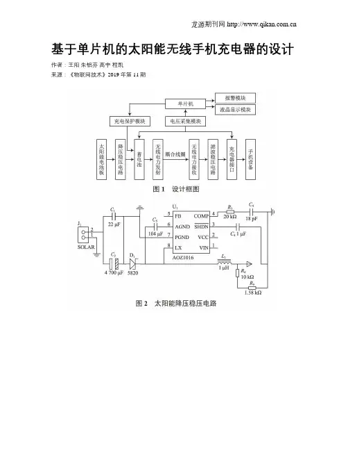
1 总体方案设计太阳能无线手机充电器主要由太阳能电池板、降压稳压电路、无线电力传输电路、单片机电压采集监控电路、无线电力接收电路、手机充电电路、充电保护电路等组成,实现将太阳能转换成电能,通过无线供电方式为手机等设备供电。
具体设计框图如图1所示。
2 硬件设计2.1 太阳能充电及降压稳压电路设计利用太阳能电池板可直接将光能转换为电能,为了解决太阳光照强度不稳定导致电压不稳定的问题,本文采用多块太阳能电池板进行串并联以提高电压,再利用稳压器降压后给蓄电池供电,从而确保输出相对稳定的电压。
基于MSP430无线对讲机的研究与设计【摘要】无线对讲机具有使用简单、不受网络限制、通话成本低、适用范围广等优点。
目前对讲机作为一种便利的信息沟通工具已经应用在很多领域。
无线对讲机主要是由发射和接收两部分组成,本文主要研究基于MSP430无线对讲机的国内外发展状况,接收和发射部分的组成及设计方案、技术参数以及对讲机的应用等。
【关键词】无线对讲机;发射;接收1.引言无线对讲机作为一种简单的通讯工具,由于它不需要中转和地面交换机站支持,就可以进行移动通信。
它是在鉴频、混频等技术的基础上,利用无线电通信原理研发的一种通信方式,目前广泛应用于生产、保安、野外工程等领域的小范围通信工程中。
无线对讲机主要是由发射和接收两部分组成,发送原理是把音频信号转变成电信号,再通过调制之后利用特定的频率范围发送出去。
接收是利用接收器对特定的频率范围之内收到的信号通过解调之后通过扬声器发出收到的信息声音。
本文主要研究了基于MSP430无线对讲机的国内外发展状况,无线对讲机接收部分和发射部分的组成及设计方案、技术参数以及应用等。
2.对讲机的国内外发展状况传统的模拟对讲机设备在追求生产效率以及经济效益的今天,在公共安全、应急调度、物资流通、货运、交通、建筑施工工、物业管理、餐饮用血等各个领域扮演着重要的角色。
但是的传统的模拟对讲机设备频谱利用率低,易受干扰,保密性差,业务单一等一些不可避免的缺陷已经逐渐地体现出来。
因此,失去传统的模拟通信设备通信向数字化发展将是解决这些缺陷的非常有效的办法。
目前,对讲机的数字化已受到高度重视。
数字对讲机设备的技术和标准化工作在欧美等发达国家已开始推进。
我国信息产业部无线电管理局在2007年9月13日发布了《数字对讲机系统设备无线射频技术指标要求》(试行)和2009年12月12日发布的《150MHz、400MHz频段数字对讲机设备无线技术指标》的通知,为我国数字对讲机的发展提供了频率保证和射频基本指标要求,也使得国内通信制造商的研发有章可循,从而促进了国内数字对讲机设备的研发。
题目:无线传能充电器指导老师:邓柳李德明队员及年级:罗国见欧明亮李键(2006 级)学校及院系:长江职业学院工学院摘要本无线传能充电器由能量发送单元和能量接收单元两大部分组成,可在6cm的距离以内对电池进行快速和慢速充电。
能量发送端可用市电和直流电源供电,具有交流优先和交直流自动切换的功能;接收端控制电路采用MSP430 低功耗单片机,电压和充电时间显示采用低功耗OCM126864-9 液晶屏。
AbstractThe wireless energy transmitting charger is made up of an energy transmitting unit and an energy receiving unit. Battery can be charged by this system in two modes(quick mode /slow mode) with the distance upto 6cm. The energy transmitting unit can be powered by AC or direct current and AC is a high periorty. Energy receiving unit is made up of charge-circuit and control-unit which controled by MCU named MSP430.The charging process will be monitored by lcd(OCM126864-9) .1 方案设计1.1 理论分析本系统设计的关键点一是用线圈耦合方式传递能量,使接收单元接受到足够的电能,以保证后续电路能量的供给;二是如何提高充电电路的能量利用效率,在满足充电电路正常工作的前提下尽可能采用低功耗设计。
1.2 选用TI 器件的依据,选择理由,所选TI 器件详细介绍依据:为了保证充电器的稳定性,准确性;实现充电过程的实时监控。

基于CC1100和MSP430的无线UART实验设计随着计算机技术的发展和广泛应用,尤其是在工业控制领域的应用越来越广泛,计算机通信显得尤为重要。
串行通信虽然使设备之间的连线大为减少,但随之带来串/并转换和位计数等问题,这使串行通信技术比并行通信技术更为复杂,串/并转换可用软件实现,也可用硬件实现。
用软件实现串行传送大多采用循环移位指令将一个字节由高位到低位(或低位到高位)一位一位依次传送,这种方法虽然简单但速度慢,而且大量占用CPU 的时间,影响系统的性能。
更为方便的实现方法是用硬件,目前微处理器串行接口常用的LSI 芯片是UART、USART 和ACIA 等,不论是哪一种芯片,它们的一种基本功能是实现串/并转换。
正是这些串行接口芯片弥补了串行通信较为复杂这一缺陷。
因此在串行通信中,传输接口是首先需要解决的基本问题。
通用异接收发送器简称UART,是一种应用广泛的异步串行通信的传输接口,专用UART 芯片能够实现比较全面的串行通信功能,而在实际应用中往往只需要使用到UART 的部分功能,在设计中如果使用无线数据节点即KM-DONE 433,那么在剩余资源充足的情况下就可以充分利用剩余资源实现所需的UART 的功能,这样就无需再外接专门的UART 芯片,从而简化了电路,缩小了体积、提高了可靠性、并且具有了更大的灵活性。
基于以上考虑,提出一种基于CC1100 和MSP430F2132 的无线UART 实验设计,实现无线传感器节点间的通信。
1 总体设计无线传感器网络系统通常包括若干个传感器节点、一个汇聚节点和一套管理节点。
大量传感器节点随机部署在监测区域内部或附近,能够通过自组织方式构成网络。
传感器节点具有本地数据采集传输和转发邻节点数据的双重功能,传感器节点监测的数据沿着其他传感器节点逐跳的进行传输,在传输过程中监测数据可能被多个节点处理,经过多跳后路由到汇聚节点,最后通过互。
基于单片机的智能手机充电器的设计-----------------------作者:-----------------------日期:⏹⏹Improvements in Battery Charger ICs Keep Pace with Rapid Increases in Mobile HandsetCapabilitiesIn the era of global wireless connectivity, almost nothing is more important than keeping a smart phone or mobile Internet device charged. Expanding features on the constantly improving portable and handheld device create a major challenge for designers of battery charger ICs. High resolution screens and larger memories combine with new capabilities to tax the battery, requiring battery charger technology that is not only more efficient but also capable of managing power distribution.Optimizing power consumption to prolong battery life has always been a driving force in handheld power management. However what is changing are the efficiency expectations for charging handheld devices when they are plugged into the wall. The latest generations of device designs are using high-efficiency switching chargers in place of traditional linear chargers. Customers today continue to demand shorter charge cycles when charging their battery. Beside higher efficiency with respect to the conventional linear chargers, one of the great advantages of using switching chargers solution is the capability to boost the charge current from what supplied by the source. This is especially important when powering off of a USB port where the current available might be limited to less than 500mA. Higher chargecurrents equate to shorter charge cycles thus satisfying customer expectations.There are two kinds of battery chargers used in most handhelds now – linear chargers and switching devices. Linear chargers have a longer history. They have typically provided a relatively efficient, simple way to charge portable devices, creating minimal noise without many external components. But as portable devices become more complex and add layers of new features, they need higher battery capacity. Linear chargers present liabilities due to power dissipation, which become clear if a user wants to charge a device while using at the same time. The heat generated while simultaneously using and charging can damage the system or battery. Not a good outcome.The alternative is a switching device, or switch mode battery charger IC, that can deliver higher current levels to a battery while requiring as little power as possible. Historically, there have been some noise issues with these kinds of ICs. In addition, some early generations of switch mode devices have required several external components.However, the benefits of the switched mode battery topology are clear. They include higher efficiency and lower power dissipation, along with fast charging cycles. These devices also are capable of charging fromhigher input voltages, which allows the use of lower cost unregulated adapters. They can increase the charging current from current restricted sources.The noise from switching chargers usually comes during light load operation, particularly during preconditioning. As it decreases, many switching chargers move into an operation known as pulse skipping. In pulse skipping, the PWM frequency changes asynchronously. There have been battery charger ICs developed that supply high charge current with minimal thermal impact to the system using a switching charger, then switch into a linear charger during low current charging modes to minimize noise. This type of PWM switch mode charger with a linear mode has been a good development, providing high efficiency at the full constant current (fast charge) rate. The switching charger controls large constant current charge (up to 2A) with a PWM switching regulator. It automatically moves to linear mode while the battery is preconditioning and near the end of constant voltage taper charge mode, which lowers the noise while the switch mode speeds up charging. Once the charge current level dips below 300 mA, the linear mode kicks in completely and noise generated by the switching converter is eliminated.But now there are further advances. For example, an ideal solution for new handhelds is a complete charger for single cell Li+/ Polymer batteries with up to 1A charge current and advanced indication capabilities for full charge system monitoring. USB Compliant100mA/500mA charge current settings are beneficial as are programmable pre-charge and fast charge. Many products also include battery temperature monitoring, which ensures safe charging.Companies such as Intersil are leading the development effort for new generations of charger ICs. These fully integrated solutions serve compact applications and provide charge controllers for higher power applications. Charge voltage accuracy is now at 0.5 percent, an improvement over just a few years ago, when an accuracy rating of 1 percent was considered good. Switching frequencies are up to 3 MHz and new switching chargers now provide up to 2A charge current, with one recent example being the ISL9220, which is suitable for both 1 and 2 cells Li Ion applications.In addition, new designs restrict leakage -- there is no less than 0.5uA typical leakage current off the battery when no input power is attached. These improvements also have become available in smaller and smaller packages, such as 4 x 4mm QFNs or 2 x 2mm CSPs, which save real estate in space-constrained handheld equipment.The latest battery charger ICs also are able to monitor the input voltage, the battery voltage, and the charge current. When any of the three parameters exceeds specific limits, the IC turns off an internalN-channel MOSFET to remove the power from the charging system to the battery. This kind of flexible efficiency is another of the improvements now available in these important devices, which are vital to the continuing growth and feature set expansion of mobile, handheld products.【作者】Marino, Giampaolo; Schmitz, Tamara 【刊名】Electronic Component News 【出版日期】2010 【卷号】Vol.54 【期号】No.1 【页码】16DESIGN AND IMPLEMENTATION OF A MICROCOMPUTER 8051 SYSTEM POWERED BY DUAL BATTERIES CHARGED BY SOLARCELLSAbstractSingle-chip microcomputer systems are becoming increasingly popular in current control and information applications. However, due to their battery energy limitations, these systems have a veryrestricted operation time or recharge cycle if a single rechargeable battery supplies their power. We propose a design and implementation for the software and hardware of a microcomputer 8051 system powered by a dual rechargeable battery that is charged by solar cells. From a feasibility analysis of the queueing model for the stochastic charging and discharging process of the dual battery system, due to the random characteristics of weather conditions and users' operational behavior, we confirm that the average operation time for this model can be much longer than that of a single rechargeable battery power supply. The experimental results of our design also show approximately the same results as our model. With a two-thirds utilization ratio, we can obtain an average operation time four times as long in theoretical results, and three and half times as long in experimental results than with a single rechargeable battery power supply. In addition, the technology trend shows that the power consumption rate for a typical microcomputer system is decreasing and the power generation efficiency for typical solar cells is increasing. Hence, solar cells as the power charging sources for a microcomputer 8051 system supplied by a dual rechargeable battery can be feasible in the near future.Over the past few years, microcomputer system design researchers have been working with different levels of low-power technology. Interms of system, circuits, and device power saving, the results show that every year from 1992 to 1997 the average power consumption of a microcomputer computer decreased more than 20%,and from 1998 to 2001 it decreased by 10%.Reducing power consumption is important because of its potential to extend the recharge period of portable information applications. The longer the battery operation time before a recharge is needed, the more convenient it is for mobile users to operate a portable microcomputer system.Eventually, the power consumption of a single-chip microcomputer system will be small enough to be supplied or recharged by other power sources. One of the proposed power sources is mechanical vibration. Among others, we previously proposed solar cells that can be used as power supply sources. Although current mc-Si solar cell power generation efficiency is not high enough, their efficiency increased from 14.2% to 16.8%from 1990 to 1997.This improvement can reduce the gap between the charging and discharging rate of the power supply of a microcomputer system, so the probability of power exhaustion within a certain operational time is reduced each year.To prolong the battery operation time before recharging, in this article we present the software and hardware module for a single-chip microcomputer 8051 system with a dual battery charged by solar cells.Based on its design and implementation, this work also presents the estimation for power exhaustion probability and the experimental measurement for operation time that depends on the power generation efficiency of solar cells and the power consumption rate of a microcomputer. In addition, due to the overlapping of the charging and the discharging period, if the ratio between the charging and discharging rate is two thirds, then the operation time can potentially be prolonged four times in comparison with a single rechargeable battery.The rest of this is organized as follows. In Section 2, the technology trends with respect to the power consumption of a microcomputer and the power generation efficiency of solar cells are discussed. In Section 3, the queueing model for the stochastic charging and discharging behavior for the dual rechargeable battery in a single-chip microcomputer system is presented. In addition, the feasibility estimation for the dual rechargeable battery in a single chip microcomputer system is given. In Sections 4 and 5, the design and implementation of the software and hardware modules for this system are provided. In Section 6, the experimental results of this system are given. The last section presents conclusions.7. ConclusionsWe have presented the design and implementation of a microcomputer 8051 system powered by dual batteries charged by solar cells. The hardware components used are very common and are of low cost. The control program designed uses a common variety of assembly language. The experimental system has shown a very stable operation. From our observation of the theoretical and experimental results, we conclude that this dual-battery design has the potential to extend the average operation time of such a microcomputer by 200%. For a two-thirds utilization ratio in our design, we can gain four times the average operation time of a single-battery design from the theoretical results, and three and a half times the average operation time from experimental results. The difference between the theoretical results and the experimental results is a result of error in the battery-charging process. In addition, when our system operates in strong sunshine, it can work continually without battery exhaustion because the energy generation by the solar cells is greater than the energy consumption of 8051 system.【作者】Y.-W. Bai; C.-L. Chang【刊名】International Journal of Power & Energy Systems【出版日期】2002【卷号】Vol.22【期号】NO.3【页码】125-135译文电池充电器集成电路的改进跟上移动手机功能快速增长的速度在全球无线连接的时代,几乎没有什么比让一个智能手机或移动互联网设备保持带电更重要了。
基于单片机的无线充电器设计学生:学生学号:院(系):电气信息工程学院年级专业:电子信息工程指导教师:助理指导教师:二〇一五年五月摘要随着用电设备对供电质量、可靠性、方便性、安全性、特殊场合、特殊地理环境等要求的不断提高,接触式的电能传输方式对于满足实际需要越来越显得捉襟见肘了。
与此同时,无线电能传输系统,摆脱了线路的限制,实现电器和电源的完全分离,具有无线传输电能、设备体积小、传输效率高、便于携带和集成等优点。
本课题设计介绍了一种运用新型的能量传输利用电磁波感应原理和有关的交流感应技术,采用STC12C5A60S2低功耗单片机作为无线传能充电器的监测控制核心,实现电流控制和电压控制功能,电能充满后给出充满提示且自动停止充电。
基于STC12C5A60S2单片机控制发射端和接收端产生的相应交流信号来进行充电的智能无线充电器。
利用设计通过对系统的硬件部分和软件部分的设计实现无线能量传输,在距离发射线圈的指定围对小型用电器如手机、MP3等直接充电。
硬件部分包括高效直流稳压模块、驱动模块、显示模块、控制模块等的设计;软件部分主要根据系统的设计思想设计出了主程序和子程序流程图,并通过C语言实现相应的编程要求。
通过理论分析和仿真证明,建立谐振耦合无线电能传输系统模型以及谐振耦合无线电能传输系统模型,通过计算得出了系统中电路参数与输出功率的关系。
设计并制作谐振耦合无线电能装置,使用LCD1602设计显示,实时充电电压显示。
关键词无线电能传输,谐振耦合,无线充电器, LCD1602,STC12C5A60S2单片机ABSTRACTThis paper introduced the use of a power transmission technology, wireless power supply technology model, using the principle of electromagnetic induction and the induction technology,intelligent wireless charger for charging the AC signal based on the STC12C5A60S2 single-chip microcomputer to control the transmitting end and the environment and other requirements continue to increase, the power transmission mode of contact to meet the actual needs become more and more difficult. At the same time, wireless power transmission system, get rid of the limit line, completely separate electrical and power, with the wireless transmission of electrical energy, the equipment has the advantages of small volume, high transmission efficiency, easy to carry and integration. In the rapid development of science and technology in 21 Century, the prospects for the development of intelligent wireless charger . The design through the design of the hardware part and the software part of the system to achieve the wireless energy transmission, within the specified range of the transmitting coil in small appliances such as mobile phone, MP3 and other direct charge. The hardware part includes efficient DC power module, drive module, display module, control module and so on; the software part is mainly based on the design thought of the system design of the main program and the subprogram flow chart, and through the C language to achieve the corresponding programming requirements. relationship between the circuit parameters and the output power of the system. The design and fabrication of resonant coupling wireless device, using the LCD1602 design draw progress bar shows charging, charging voltage, charging time display.Key words radio transmission, resonant coupling, wirelesscharger ,LCD1602 STC12C5A60S2目录摘要 (I)ABSTRACT (II)1 绪论 (1)1.1课题背景 (1)1.2 国外研究现状、水平 (1)1.3本课题的发展趋势 (2)2 系统总体设计方案 (4)2.1系统总体设计方案简述 (4)2.1.1系统的基本功能 (4)2.1.2主要技术参数 (4)2.2系统设计方案选择 (5)2.3方案分析 (7)2.4系统的理论分析 (8)3 系统的硬件设计 (10)3.1单片机的选择与其控制 (10)3.1.1 单片机概述 (10)3.1.2 单片机STC12C5A60S2的介绍 (10)3.1.3 单片机最小系统的介绍 (11)3.1.4单片机控制模块设计 (13)3.2无线发射电路模块设计 (14)3.2.1 NE555芯片简介 (14)3.2.2 MOS管的选择与性能分析 (15)3.2.3振荡电路的设计 (16)3.2.4功率放大电路的设计 (17)3.3 电源稳压控制模块设计 (18)3.3.1稳压器LM2940简介 (18)3.3.2 KA7500B芯片简介 (18)3.3.3稳压控制电路设计 (19)3.4按键指示电路模块设计 (20)3.5显示电路设计及实现 (21)3.6 DC/DC转换电路设计 (23)3.6.1 DC/DC变换器简介 (23)3.6.2 运算放大器LM358简介 (24)3.6.3电压/电流采样模块设计 (24)3.7系统总体电路设计 (26)4 系统的软件设计 (28)4.1 整体设计思想 (28)4.2系统的主要程序框图 (29)4.3 主要程序模块 (29)4.3.1电路启动初始化 (29)4.3.2 按键采集程序 (30)4.3.3 LCD1602显示子程序 (31)4.3.4 数据采集及模数转换程序 (31)4.3.5 充电子程序的设计 (32)5 系统仿真设计与调试 (34)5.1.仿真软件Multisim的简介 (34)5.2电路的仿真 (34)5.2.1方波信号的产生 (34)5.2.2实际电路的测试 (36)5.3测试结果及分析 (37)5.3.1测试结构 (37)5.3.2实际电路的测试数据 (37)6 系统PCB设计 (39)6.1 PCB设计软件简介 (39)6.2 PCB板设计方法 (39)7 组装与调试 (41)7.1系统组装 (41)7.2硬件调试 (41)7.3软件调试 (41)7.4硬件软件联合调试 (41)7.5 调试结果 (41)结论 (42)参考文献 (43)附录A:无线充电控制系统源程序代码 (44)附录B:整体电路图和PCB板图 (54)附录C:设计实物图 (56)致.............................................. 错误!未定义书签。
基于单片机的锂电池充电器设计锂电池是一种高能量密度、长寿命、轻巧的电池,被广泛应用于便携式电子设备、电动工具、无人机等领域。
为了正确而安全地充电锂电池,我们可以设计一个基于单片机的锂电池充电器。
本文将详细介绍此设计。
首先,我们需要明确设计的目标和要求。
一个理想的锂电池充电器应具备以下特点:充电电流可调;充电电流稳定性好;电池充电过程可实时监测;充电接口友好;具备过充保护、过放保护等安全保护机制。
基于这些要求,我们可以开始设计锂电池充电器。
一、电路设计1.电源电路设计:我们可以采用交流-直流变换的方式,将交流电源转换为直流电源供给锂电池充电器。
这里我们选择了一个标准的变压器、整流桥和滤波电容组成的整流电源模块。
变压器将交流电压转换为较低的交流电压,整流桥将交流电压整流为直流,滤波电容将直流电压进行平滑。
2.充电控制电路设计:充电控制电路是整个充电器的核心部分。
我们选择使用单片机作为控制器,采用PWM控制方式调节充电电流。
单片机内置了计数器和定时器功能,可以根据设定的参数控制PWM输出,实现电流的调节。
通过监控电池电压和充电电流,单片机还可以进行实时监测和保护控制。
3.充电保护电路设计:为了确保充电过程的安全,我们需要设计过充保护电路和过放保护电路。
过充保护电路主要用于监测电池电压,当电池电压超过设定的阈值时,会切断充电电路,以避免过充。
过放保护电路主要用于监测电池电压,当电池电压低于设定的阈值时,会切断充电电路,以避免过放。
这些保护电路一般使用功率MOS管来实现。
二、软件设计为了实现充电器的功能,我们需要编写相应的软件程序。
软件程序主要包括以下几个方面的功能:1.充电控制功能:根据选择的充电电流设置,通过PWM控制充电电流,并实时监测电池电压和充电电流。
2.充电保护功能:在充电过程中,实时监测电池电压,一旦电池电压超过设定的阈值,立即切断充电电路,避免过充。
一旦电池电压低于设定的阈值,立即切断充电电路,避免过放。
目录第1节引言 (2)1.1 蓄电池的特点 (2)1.1.1镍铬电池和镍氢电池 (2)1.1.2锂离子电池 (3)1.2 智能充电器 (3)1.3 本设计功能模块 (4)第2节系统设计思路分析 (4)2.1 智能化的实现 (5)2.2 电池充电芯片的选择 (5)2.2.1 如何选择电池充电芯片 (5)2.2.2 芯片MAX1898 的特点 (6)2.2.3 MAX1898 的充电工作原理 (6)第3节系统主要硬件电路设计 (9)3.1 主要器件 (9)3.2 电路原理图及说明 (10)第4节系统的软件设计 (13)4.1 程序流程 (13)4.2 程序说明 (13)结束语 (16)参考文献 (17)附录 (18)基于单片机的智能充电器设计第1节引言目前,一部分的充电器不但能在很短的时间里将电量充足,而且还可以对电池起到一定的维护作用,修复由于使用不当造成的记忆效应,即容量下降现象。
设计比较科学的充电器往往采用专用充电控制芯片配合单片机控制的方式。
专用的充电芯片可以检测出电池充电饱和时发出的电压变化信号,比较精确地结束充电工作,通过单片机对这些芯片的控制,可以实现充电过程的智能化,例如,在充电后增加及时关键电源、蜂鸣报警和液晶显示等功能。
充电器的智能化可以缩短充电的时间,同时能维护电池,延长电池使用寿命。
51系列单片机也是当前使用最为广泛的8位单片机系列,其丰富的开发资源和较低的开发成本,使51系列单片机现在以致将来都仍会有强大的生命力。
在众多的51系列单片机中,AT89系列单片机在我国得到了极其广泛的应用,AT89系列单片机是美国Atmel公司的8位机产品。
它的特点是片内有Flash Memory是一种电可摩除和电写入的闪速存储器(记为FPEPROM),在系列的开发过程中可以很容易地进行程序修改,使开发调试更为方便。
随着社会的不断发展,人们使用各种家电设备、仪表以及工业生产中的数据采集与控制设备也在逐步走向智能化,所以充电器有它的巨大发展空间,同时电子产品的不断更新。
基于 MSP430 单片机的无线充电器设计
引言
目前,手机、MP3 和笔记本 电脑等便携式电子设备进行充电主要采用
的是一端连 接交流电源,另一端连接便携式电子设备充电电池的传统充电方
式。这种方式有很多不利 的地方,如频繁的插拔很容易损坏接头,也可能带
来触电的危险等。因此,非接触式感应充电器在上个世纪末期诞生。凭借其携
带方便、成本低、无需布线等优势迅速受到各界关注。实现无线充电,能量传
输效率高,便于携带成为充电系统的研究方向之一 。本设计就是一个由能量
发送单元和能量接收单元两大部分组成,利用电磁感应原理 实现电能无线传
递的充电器。
1 硬件系统设计
1.1 器件选择
本无线充电系统的设计是用线圈耦合方式传递能量,使接收单元接收到
足够的电能,以保证后续电路能量的供给。由于无线传电电压随能量发送单元
和接收单元耦合线圈的间距 D 在测试中需要改变,而充电时间相对固定,便于
控制,所以充电方式上选择固定电流充电的恒流充电方案。在器件选择上选择
有多种省电模式,功耗特别省,抗干扰力特强的 MSP430 系列超低功耗单片机
MSP430F2274 作为无线传能充电器的监测控制核心芯片,电压和充电时间显示
采用低功耗 OCM126864—9 液晶屏,以提高充电电路的能量利用效率。
1.2 系统框无线充电系统主要采用电磁感应原理,通过线圈进行能量耦
合实现能量的传递。如 1.3 单元电路设计
1.3.1 电源切换
直流输入采用单刀双闸继电器,交流上电常开闭合,常闭打开实现交流