PSX 643U规约转换器技术说明书_V1.0
- 格式:pdf
- 大小:486.41 KB
- 文档页数:18
规约转换器PSX640(COM板)软件使用说明国电南京自动化股份有限公司2001.08一、硬件概述本规约转换器分为PSX640和COM板两种类型。
其中PSX640为独立设备,它具有一个以太网接口,一个RS232/422/485接口,一个6位指拨开关;COM板为插件式模块,借用PSR650或PSX600电源,它具有三个以太网接口,两个RS232/422/485接口,一个8位指拨开关。
1、以太网的使用接至设备端时,应采用交叉线,接至HUB时,应采用直通线。
COM板三个接口的网络号部分不能相同。
目前子网掩码保留为255.255.0.0。
2、RS232/422/485的使用✓RS232管脚:2=收,3=发,5=公共地;RS422/485管脚:1=OUT-,2=OUT+,3=IN+,4=IN-。
✓方式选择由指拨开关决定,1、2号开关用于串口1,其中,1、2在OFF位置为232方式;1在ON位置为422方式;2在ON位置为485方式。
3、4号开关用于串口2(COM 板),方法类推。
方式选择是一种软跳线,最终由软件决定,改变开关设置后,只有在设备再次上电后才会有效。
✓COM板串口硬件接线分别由JP5-JP6(串口1)和JP7-JP8(串口2)设置,当工作在422/485方式时,需短接1-2;工作在232方式时, 需短接2-3。
PSX640采用了电子切换方式,只需使用相应的插座,无需设置硬件接线。
3、参数设置✓将COM板指拨开关7/8(PSX640:5/6)置于ON位置,使用串口线连接PC机和COM 板串口1/2(需设置为232接线方式)或PSX640的RS232口,上电。
✓启动Windows超级终端,设置PC串口波特率9600,数据位8,无校验,1位停止位, 【ASCII码发送】选项选中【以换行符作为发送行末尾】,【ASCII码接收】选项选中【将超过终端宽度的行自动换行】,按回车键,输入用户名(sac)和用户密码(1234),将显示选择菜单,可进行相应参数的设置。

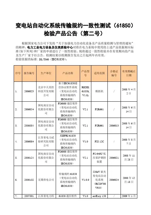
变电站自动化系统传输规约一致性测试(61850)检验产品公告(第二号)
根据国家电力公司下发的“关于加强电力自动化设备及产品质量检测与管理的通知”的精神,电力工业电力设备及仪表质检中心对将在电力系统中使用的上述产品依据相应标准(如下所列)和厂家的申请进行了一致性检验。
现将通过一致性检验并在有效期内的产品及生产厂家予以公告。
检测结果以检测报告发出之日起两年内有效。
检验依据的标准: DL/T860(IEC61850);
电力工业电力设备及仪表质检中心
2008年1月14日
地址:北京清河小营东路15号中国电力科学研究院内
电话:(010)62931468 62935015 82812379
邮编:100192
联系人:蔡青有,陆天健
E-mail: caiqy@,ltj@,。

3.3 DEC板卡应用实验3.3.1 数字I/O实验1——交通灯实验3.3.1.1 实验目的1. 熟悉使用SEED-DEC643板控制SEED-DTK_MBoard上交通灯的方法;2. 掌握DSP扩展数字I/O口的方法;3. 了解SEED-DEC643的硬件系统。
3.3.1.2 实验内容1. DSP的初始化;2. TMS320C643的扩展数字I/O口使用;3. 交通灯控制程序。
3.3.1.3 实验背景知识3.3.1.3.1 DSP系统中数字I/O的实现DSP系统中一般只有少量的数字I/O资源,而一些控制中经常需要大量的数字量的输入与输出。
因而,在外部扩展I/O资源是非常有必要的。
在扩展I/O资源时一般占用DSP 的I/O空间。
其实现方法一般有两种:其一为采用锁存器像74LS273、74lS373之类的集成电路;另一种是采用CPLD在其内部做锁存逻辑,我们采用的是后者。
SEED-DEC643的存储器扩展总线,包含4个存储空间,每个存储空间有20-位地址线、32-位数据线。
SEED-DEC643的这4个存储空间被映射到’DM643的和空间中,具体的映射关系如下表所示:扩展总线EMIF EA[22:19] 字节地址†长度1xxB 0xB020 0000~0xB03F FFFF512K×32-位10xB 0xA020 0000~0xA02F FFFF256K×32-位110B 0xA030 0000~0xA037 FFFF 128K×32-位111B 0xA038 0000~0xA03F FFFF128K×32-位†、空间被配置为32-位存储器时的逻辑地址在SEED-DEC643上,存储器扩展总线只支持8/16/32-位数据宽度,不支持64-位数据宽度。
存储器扩展总线的20-位地址线XA[21:2]由’DM643的EMIF总线的地址总线EA[22:3]经驱动后提供,32-位数据总线XD[31:0]则由’DM643的EMIF总线的低32-位数据总线ED[31:0]经驱动后提供,4-位存储空间选通线由’DM643的、与地址译码后提供,4-位字节使能线由’DM643的EMIF总线的字节使能的低4-位经驱动后提供,读/写控制线有’DM643的EMIF总线的读/写控制线经驱动后提供。
The Technical Specifications of TransformerProtection and Monitoring DeviceGuodian Nanjing Automation Co., Ltd.GUODIAN NANJING AUTOMATION CO., LTD4 11 2016281.2.Monitoring and controlling function settings (1)2.Technical parameters ....................................................................................................2 2.1.Precise scope of work on protection components....................................................2 2.2.Setting error on protection components...................................................................2 2.3.Protection of the entire set of action time.................................................................2 2.4.Technical parameters of measurement and control functions...................................2 3.Protection function and principle ...............................................................................3 3.1.Phase over-current protection...................................................................................3 3.1.1Low-voltage blocking elements............................................................................3 3.1.2Negative sequence overvoltage blocking elements..............................................3 3.1.3White current inverse time protection..................................................................3 3.2.Overload protection..................................................................................................4 3.3.Zero sequence over-current protection.....................................................................4 3.4.Zero sequence overvoltage protection.....................................................................4 3.5.Low-voltage protection............................................................................................4 3.6.Acceleration.............................................................................................................4 3.7Non-power protection...............................................................................................4 3.8Tripping logic matrix................................................................................................5 3.9TV break...................................................................................................................54.Terminal Description ....................................................................................................6 4.1.Total terminal plans..................................................................................................6 4.2.AC module terminal definition of X1......................................................................6 4.3.CPU module terminal definition of X2....................................................................7 4.4DIO module terminal definition of X3......................................................................8 4.5DIO module terminal definition of X4......................................................................8 4.6TRIP module terminal definition of X5.....................................................................8 4.7TRIP module terminal definition of X6.....................................................................95.Setpoint tuning instructions.........................................................................................10 5.1List and instruction of protection value....................................................................10 5.2 List and instruction of operating parameters...........................................................12 5.3 List and instruction of Soft platen...........................................................................126.Device information code table .....................................................................................14 6.1Event information table.............................................................................................14 6.2Alarm information table............................................................................................14 6.3Soft platen information table.....................................................................................15 6.4Remote Communication information table...............................................................15 6.5Remote measurement information table....................................................................16 6.6 Remote controlling information table ......................................................................167.Device of secondary wiring diagram . (18)4 11 2016281.OutlinePST 645U transformer protection and monitoring device applies to the non-direct groundingsystem or low resistance grounding station which voltage level is below 110KV.It can be screened or installed grounding.1.1Protective function configuration1) three sections of the composite voltage lockout over-current protection (III segment can be set to the inverse time)2) The three sections of high-pressure side of the zero-sequence over-current protection (III segment alarm / trip option)3) The three sections the low pressure side of the zero-sequence over-current protection (III segment can be set to the inverse time)4) overload (alarm / trip option)5) zero sequence overvoltage protection (alarm / trip option)6) Low voltage protection 7) Hand accelerate protection 8) 4-way non-power protection1.2 monitoring and controlling functions configuration 1) 22-way external switch input and tele-signal collection;2) The circuit breaker position, manual switching accident tele-signal collection;3) normal breaker which switching is remote;4) 2 pulse input, accumulated electrical;5) time of GPS is adaptive when input.2Technical parameters2.1 precise working scope or protection of components Voltage: 1.0V ~ 150.0V;Current: 0.04IN ~ 20IN;Zero Sequence Current: 0.02A ~ 12.0A.Note: IN the rating, the same below.2.2 Protection element setting errorCurrent components: ≤ ± 2.5% or ± 0.01IN;The voltage element: ≤ ± 2.5% or ± 0.005UN;The time element: definite time ≤ (% 1 setting value) +40 ms.Note: Voltage is rating,the same below.2.3 protecting the entire group of action timeInstantaneous trip current: 1.5 times of the setting value is not greater than 40ms.2.4Technical parameters of monitoring and controlling functions R efer to PS 640U series protection and monitoring device manual4 11 2016280.04IN ,it is sentenced for three-phase voltage loss;2) three-phase voltage is greater than 8V, the minimum line voltage is less than 16V;3) That three-phase voltage is greater than 8V ;the maximum line voltage and minimum line voltage difference is greater than 16V is sentenced to two-phase or single-phase TV break.When the operating parameters of the control word KG1.5 = 1 ",select angle wiring corresponding bus PT taking VV wiring and its breaking criterion is as follows:1) negative sequence voltage is greater than 8V;2) one phase or two-phase line voltage is less than 70V pressure value;3) three-phase line voltage is less than 70V pressure value and a phase current is greater than 0.04IN.TV wiring in these two meets after the breaking criterion any conditions 10s, the device sent busbar TV disconnected "message and lit warning lights.When TV break is detected, the device can be under the control word KG1.13 and choose to exit the band voltage components paragraphs protection or voltage components. The TV disconnection detection function can be controlled by the word "KG1.14".4Terminal Description 4.1Total terminal plans4 11 201628处级本教材,》纳入学习的马克思主义立情怀、务实思路、“五位一体”总体布面的深刻内涵和要求。

PSL 646数字式线路光纤电流差动保护装置技术说明书使用说明书编写兰金波楼红勇王家华王胜审核王文雄批准马文龙V1.40二○○二年八月国电南京自动化股份有限公司*本说明书可能会被修改,请注意最新版本资料第一部分技术说明书目次声明 (1)安全标准 (1)1.装置简介 (2)1.1.装置的特点: (3)2.技术参数 (6)2.1额定参数 (6)2.2主要技术性能 (6)2.3绝缘性能 (7)2.4抗电磁干扰性能 (8)2.5机械性能 (8)2.6环境条件 (9)3.装置硬件 (10)3.1.机箱结构 (10)3.2.交流插件 (10)3.3.CPU插件 (11)3.4.电源插件 (13)3.5.逻辑及跳闸插件 (13)3.6.人机对话(MMI)插件 (14)4.保护原理 (15)4.1.光纤电流差动保护原理 (15)4.2.方向元件 (17)4.3.低电压元件 (18)4.4.过电流元件 (18)4.5.零序过电流元件 (18)4.6.反时限元件...................................................................................................................... 错误!未定义书签。
4.7.加速 (18)4.8.三相重合闸(可选) (19)4.9.低频元件(不用).......................................................................................................... 错误!未定义书签。
4.10.过负荷元件(不用) (19)4.11.PT和CT断线检测 (19)4.12.数据记录 (20)5.与变电站自动化系统配合 (21)6.定值及整定说明 (22)6.1.PSL646数字式线路光纤电流差动保护装置的整定值清单及说明 (22)6.2.PSL646数字式线路光纤电流差动保护装置的软压板清单及说明 (25)·声明·声明恭喜您购买了国电南京自动化股份有限公司的数字式保护及自动化产品—数字保护及自动化技术的国内领先者。

PSX 640网络通信服务器使用说明书国电南京自动化股份有限公司PSX 640网络通信服务器1 主要用途:PSX 640网络通信服务器主要有两个方面的用途:1)用作网络打印服务器,实现多台保护与控制装置共享打印机。
2)用作变电站内简单智能设备规约转换器。
以下即为PSX 640网络通信服务器的结构示意图:2 功能配置介绍2.1 网络打印服务器传统的保护及控制设备,往往是一台装置配一台打印机,这样一方面增加了成本,另一方面也加大了用户维护工作量。
PS 6000变电站自动化系统的所有保护及控制设备,均设置了嵌入式以太网接口,并集成了IEC870-5-103规约,从而使得多台装置共享打印机成为可能。
打印服务器就是用于实现系统中多台设备共享打印机的装置。
打印服务器的连接方式:打印服务器通过RS-232接口与打印机连接,通过RJ-45以太网接口与保护及控制设备的以太网络连接。
外接电源接至AC~220,打开打印机即可实现网络打印服务。
在PSX 640网络通信服务器用作打印服务器功能前,需对其进行下列设置:1)PSX 640网络通信服务器设置为打印服务器方式确认拨子开关1在OFF位置,此时PSX 640网络通信服务器被设置为打印服务器方式。
在该方式下,即可通过本设备完成网络打印功能。
2)设置打印服务器地址在同一个以太网络中,可同时支持多台打印机,网络中的保护及控制装置依靠网络通信服务器的地址来区分各台打印机,故在同一个网络中,PSX 640网络通信服务器的地址应设置成不同。
网络通信服务器地址= 网络通信服务器基准地址+ 偏移地址。
其中网络通信服务器基准地址在本设备内部已固定,使用者不必关心。
偏移地址由网络通信服务器背后的拨子开关3~6选择其状态与偏移地址。
2.2 规约转换器PS 6000变电站自动化系统采用了开放式设计思想,因而在站内通信网络的各层都采用了标准化的设计,其它制造商的设备完全可以使用通用的技术直接接入PS 6000的站内网。
Dell Latitude 6430u 用户手册管制型号: P36G管制类型: P36G001注、小心和警告注: “注”表示可以帮助您更好地使用计算机的重要信息。
小心: “小心”表示可能会损坏硬件或导致数据丢失,并说明如何避免此类问题。
警告: “警告”表示可能会造成财产损失、人身伤害甚至死亡。
© 2013 Dell Inc.本文中使用的商标:Dell™、Dell 徽标、Dell Boomi™、Dell Precision ™、OptiPlex™、Latitude™、PowerEdge™、PowerVault™、PowerConnect™、OpenManage™、EqualLogic™、Compellent™、KACE™、FlexAddress™、Force10™和 Vostro™是 Dell Inc.的商标。
Intel®、Pentium®、Xeon®、Core®和 Celeron®是 Intel Corporation 在美国和其他国家/地区的注册商标。
AMD®是 Advanced Micro Devices Inc.的注册商标,AMD Opteron™、AMD Phenom™和 AMD Sempron™是 Advanced Micro Devices, Inc.的商标。
Microsoft®、Windows®、Windows Server®、Internet Explorer®、MS-DOS®、Windows Vista®和 Active Directory®是 Microsoft Corporation 在美国和/或其他国家/地区的商标或注册商标。
Red Hat®和 Red Hat® Enterprise Linux®是 Red Hat Inc. 在美国和/或其他国家/地区的注册商标。