DMKY电阻应变式微型孔隙水压力计渗压计说明书南京丹陌
- 格式:doc
- 大小:138.00 KB
- 文档页数:3
葛南仪器 VWP型振弦式渗压计(智能识别)VWP型振弦式渗压计适用于各类水利水电工程,长期埋设在水工结构物或其它混凝土结构物及土体和基岩内部,监测结构物或土体内部埋设位置渗透(孔隙)水压力,并同步测量埋设点的温度。
振弦式渗压计特点:智能识别、同步温度、避雷保护、全不锈钢;渗压计加装配套附件可在测压管道、地基钻孔中使用。
1 振弦式渗压计仪器特点:智能识别、同步温度、避雷保护、全不锈钢;适用于各类水利水电工程长期埋在水工结构物或其它混凝土结构物及土体和基岩内部;振弦式渗压计全不锈钢结构;振弦式渗压计产品符合(GB/T 3411.1-2009《大坝监测仪器振弦式孔隙水压力计》、GB/T 15406-2007《岩土工程仪器基本参数及通用技术条件》、GB/T 24105-2009《岩土工程仪器基本环境试验条件及方法》、GB/T 13606-2007《岩土工程仪器振弦式传感器通用技术条件》)等技术标准。
葛南仪器振弦式渗压计产品取得全国工业产品生产许可证。
2 振弦式渗压计系列及型号:葛南仪器VWP型振弦式渗压计主要有VWP-1、VWP-2、VWP-4、VWP-6、VWP-10、VWP-16、VWP-25等系列及型号。
3 振弦式渗压计用途:适用于长期埋设在水工结构物或其它混凝土结构物及土体内,测量结构物或土体内部的渗透(孔隙)水压力,并可同步测量埋设点的温度。
适用于水利水电工程长期渗流监测,可埋设和安置在:水工建筑物、大坝(基础、垫层、回筑区、碾压层、砌料中)、混凝土、砂卵石、土体、基岩、廊道、测压管等被监测结构物内部。
2500F —渗压计的实时测量值,单位为F;T —温度的实时测量值,单位为℃;T0 —温度的测量基准值,单位为℃。
Q —若大气压有较大变化时,应予以修正。
注:频率模数F=Hz2×10-3;在标准大气压下,1m水柱=9.81kpa。
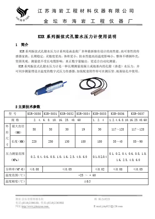
KXR 系列振弦式孔隙水压力计使用说明1 简介KXR 系列振弦式孔隙水压力计系列是函盖我厂多种最新独有设计的高性能、高可靠性的传感器家族。
长期稳定,灵敏度更高,体积更小,防水性能高而温度影响小,整体不锈钢外壳,坚固美观。
测量值不受长电缆影响,真正数字量输出,更适合自动化测量。
KXR 系列振弦式孔隙水压力计是一种长期测量混凝土或地基内的孔隙(渗透)水压力,并可同步测量埋设点温度的数字式压力传感器。
加装配套附件即可在测压管、地基钻孔中使用。
2主要技术参数地址:金坛市儒林镇东街 邮 编:213225电话:(0519)2566188; 传真:(0519)2565988网址:http// E-mail:jshy025@金 坛 市 海岩 工 程 仪 器 厂金坛市海岩工程仪器厂3验收与质保措施3.1用户开箱验收仪器,先检查仪器的数量,规格与装箱清单是否相符,如有不符,请及时与我厂联系。
3.2用250V兆欧表分别检查仪器常温绝缘电阻是否达到50MΩ,并用XP02振弦频率读数仪测量仪器的频率值及温度值。
一般情况,温度值应为测量地气温值,误差±0.5℃。
频率值应当在卡片给出的频率初始值上下20H Z 范围内。
上述事项若有异常,请与我厂联系。
3.3开箱后的仪器应保存在湿度小于80%的房间内,室内不能含有腐蚀性气体,存放环境须干燥,通风,搬运时应小心轻放,切忌剧烈振动。
4埋设与安装KXR系列振弦式孔隙水压力计的使用场合很多,如用于测量混凝土的孔隙水压力、土壤的孔隙水压力、压力钢管的内外水压力及基岩的扬压力、测压管的水位等。
埋设安装应根据不同的使用条件进行考虑。
以下介绍常见混凝土孔隙水压力计的埋设方法。
4.1进水条件:必须确保仪器的进水口畅通,谨防水泥浆堵塞进水口,为此应在进水口中用中砂、细砂做成人工的过滤层,滤层直径为8cm。
4.2仪器预饱和:由于混凝土的渗透系数很小,而孔隙水压力计前盖空腹内有一定容积,需要一定的水量才能充填满。
孔隙水压计-压力式原理传感器
孔隙水压计
产品型号: YT-YL-0100系列产品简介:
用于测量不同地质层面的孔隙水压力或渗水压力。
安装时采用钻孔预埋方式。
测量原理:根据压力与水深成正比关系的静水压力原理,运用水压敏感集成元器件做的压力式孔隙水压计。
当传感器固定在水下某一测点时,该测点以上水柱压力高度加上该点高程,即可间接地测出水位高低;核心在于压力式敏感集成元器件;另外并且内置温度传感器,对外界温度影响产生的变化进行温度修正;每个传感器内部有计算芯片,自动对测量数据进行换算而直接输出物理量,减少人工换算的失误和误差;全部元器件进行严格测试和老化筛选,尤其是高低温应力消除试验,增强弦的稳定性和可靠性;另有三防处理,保证在长期恶劣环境中高成活率的问题;
主要应用于滑坡、水利大坝、基坑、水库、路基、软基、港口等工程领域。
主要技术指标:
产品图片:。
振弦式孔隙水压力计使用说明嘿,朋友们!今天咱们聊聊一个听起来有点高大上的玩意儿——振弦式孔隙水压力计。
这名字一听就觉得不简单,对吧?别担心,今天我会用简单易懂的语言把它的用法告诉你,保证你听了以后不会觉得头疼,反而会觉得特别有趣。
先来点背景知识,振弦式孔隙水压力计主要用来测量土壤中水的压力。
你想想,地面下有多少神秘的水,土壤又是怎么和水互动的,这可都是工程师们需要搞明白的事情。
尤其是建设大楼、桥梁、隧道的时候,这玩意儿可是非常关键。
它能告诉我们土壤的“脾气”,什么时候水位高、什么时候水压大,让我们可以做出明智的决策。
听起来是不是特别牛?好了,接下来咱们就来看看怎么使用它吧。
你得找一个适合安装的地方,这个地方可得注意,不然水压测不准可就麻烦了。
一般来说,深埋在土壤中是最合适的,记住,越深越好,不然土壤的“嘴”可会发出怪声哦!安装的时候,先把孔隙水压力计的底座稳稳地放在土壤里,确保它不会东摇西晃,这样才能精确测量。
听起来简单吧,但别小看这一步,稳固是关键!装好以后,就得把它的连接线接好。
这时候你可要小心点,别让线缠到一起,搞得一团糟。
连接线就像是一根神经,负责把土壤的“心声”传递给你。
接上之后,调试一下,看看有没有信号。
如果有,恭喜你,你成功了!不过,如果没有,那可得重新检查一遍,是不是哪个地方没弄对。
接下来就是最刺激的部分了,数据读取!打开显示器,看看这个小家伙给你反馈了啥。
有时候显示的数据就像是一个古怪的谜语,需要你慢慢解读。
别着急,数据通常会告诉你土壤中的水压力,有的地方压力高,有的地方压力低。
就像每个人的性格不同,土壤的“性格”也不一样。
在使用的过程中,有时候你可能会遇到些小问题。
比如说,有时候显示的数值忽高忽低,像是在跟你开玩笑。
这时候可别慌,先检查一下连接线有没有松动,或者底座是不是稳当。
多半是这些小毛病造成的。
工程界常说,细节决定成败,可见这句话真是一点都不假。
对了,记得定期校准哦!这就像给你的小车定期保养,保持它的最佳状态。
南京葛南实业有限公司企业标准QS:XK07-003-00027Q /3201GNSY012—2010VWP-D型振弦式扬压力计使用说明2010—01—01实施本使用说明由南京葛南实业有限公司编制VWP-D型振弦式扬压力计使用说明本使用说明仅适用于本公司生产的VWP-D型振弦式扬压力计,其中包括有VWP-0.16D、VWP-0.25D、VWP-0.4D、VWP-0.6D、VWP-1.2D等系列型号。
1用途VWP-D型振弦式扬压力计适用于长期布设在水工建筑物的测压管内,测量测压管内扬压力的变化量,并可同步测量埋设点的温度。
振弦式扬压力计全不锈钢结构,24mm的外径,可方便的放置在含1英寸以上的测压管内。
振弦式扬压力计具有智能识别功能。
规格代号VWP-0.16DVWP-0.25DVWP-0.4D VWP-0.6D VWP-1.2D尺寸最大外径D:mm 2424242424参数长度L:mm 120120*********测量范围:KPa 0~1600~2500~4000~6000~1200性能灵敏度k:KPa/F≤0.072≤0.11≤0.18≤0.27≤0.47参数测量精度: F.S±0.1%±0.1%±0.1%±0.1%±0.1%温度测量范围:℃-40~+150-40~+150-40~+150-40~+150-40~+150`温度测量精度:℃±0.5±0.5±0.5±0.5±0.5温度修正系数:KPa/℃≈0.12≈0.12≈0.12≈0.12≈0.12阻,耐水压:测量范围 1.2倍 1.2倍 1.2倍 1.2倍 1.2倍阻:绝缘电阻:MΩ≥50≥50≥50≥50≥50注:频率模数F=Hz×103结构及工作原理3.1结构VWP-D型振弦式扬压力计由透水环、感应膜、密封壳体,信号传输电缆、振弦及激振电磁圈等组成。
一、前言:请在使用记录仪前认真阅读本说明书。
(为方便客户阅读,本说明书部份图片采用彩色图片))谢谢您的惠顾!* 您收到汤姆斯产品后,请检校验仪的外观是否有损坏,型号是否与您定货相符。
若有损坏、型号不符请立即与本公司更换。
(收到货的五个工作日内完成)* 请在产品允许的工作条件下使用。
非专业人员请不要擅自拆开记录仪,以免发生危险;如记录仪出现故障时,请先与本公司技术人员联系。
* 请不要用有机溶液清洗LCD屏幕,以免损伤屏幕。
* 仪器虽有抗震设计,但仍应非常小心轻放,特别在现场使用时,避免摔跌、冲撞。
二、概述:2.1、该精密数字压力计为交直流两用的便携式仪器,在测量压力的同时,可测量电流,同时在LCD上显示出来,并备有24V DC输出。
加之前面板上安装有打压手泵,使其成为理想的现场校验仪表。
2.2、高效能的微处理器对仪表零点和线性进行连续修正,保证仪表长时间内零点和准确度具有良好的重复性和稳定性,测量准确度高。
2.3、采用高性能cpu和温度传感器对仪表温度漂移进行自动补偿,保证准确度下的使用温度范围宽。
2.4、功耗低。
电池充满后,保证准确度下的连续工作时间长。
2.5、恒流充电,具有电池电压的过充电、欠压自动关机及自动保护功能,保证电池不因过充电或欠压而损害,电池使用寿命长(因长时间不用,隔三个月充电一次)。
2.6、微功耗的欠电压自动保护功能,保证仪表即使操作者因故而联系开机过长也不会因欠电压而损害电池。
2.7.仪表量程功能丰富,一表多用,具有多种显示风格,可同时显示压力、电流,压力、水柱或压力、公斤及电流百分比。
2.8.仪器具有超量程报警功能,当所加压力超出额定满满量程+2500字时,仪表将显示OVERRANGE!p,并且内置蜂鸣器将断续发声,表示压力超出满量程,停止加压,使用微调,进行上下调整。
当仪表所测量的电流超出22mA时仪表将显示OVERRANGE!I并且内置蜂鸣器将断续发声,表示所测电流超量程。


SXX型振弦式渗压计使用说明书水利部南京水利水文自动化研究所南京拓水科技实业有限公司SXX型振弦式渗压计SXX型振弦式渗压计,其中包括有SXX-2、SXX-3.5、SXX-4、SXX-6、SXX-10、SXX-16、SXX-25七种型号。
一、用途SXX型振弦式渗压计适用于长期埋设在水工建筑物(地基或基岩)内部和其它混凝土建筑物及土体内部,长期观测建筑物或土体内部的渗透(孔隙)水压力,亦可用于观测水库水位的变化,并可同时测量埋设点的温度。
渗压计加安装配套附件可在测压管、管道、地基钻孔中使用。
注:频率模数F=Hz2×10-3如工程特殊需要可以定做其它规格型号的仪器。
三、结构及工作原理1.结构SXX型振弦式渗压计由透水石、不锈钢感应膜片、密封壳体,信号传输电缆、振弦及激振电磁圈等组成。
2.工作原理当被测水压荷载作用在渗压计上,将引起弹性膜片的变形,其变形带动振弦转变成振弦应力的变化,从而改变振弦的振动频率。
电磁线圈激振振弦并测量其振动频率,频率信号经电缆传输至读数装置,即可测出水荷载的压力值,同时可同步测出埋设点的温度值。
3. 压力计算方法:a)当外界温度恒定,渗压计仅受到渗透(孔隙)水压力时,其压力值P与输出的频率模数ΔF具有如下线性关系:P = kΔFΔF = F0 - F式中:k—渗压计测量压力量的最小读数,单位为KPa/F ;ΔF—渗压计基准值相对于实时测量值的变化量,单位为F;(Hz2/1000)F—渗压计的实时测量值,单位为F;(Hz2/1000)F0—渗压计的基准值,单位为F:(Hz2/1000)b)当作用在渗压计上的渗透(孔隙)水压力恒定时,而温度增加ΔT,此时渗压计有一个输出量ΔF´,这个输出量仅仅是由温度变化而造成的,因此在计算时应给以扣除。
实验可知ΔF´与ΔT具有如下线性关系:P´= kΔF´+bΔT = 0kΔF´= -bΔTΔT = T - T0式中:b—渗压计的温度修正系数,单位为KPa /℃;ΔT—温度实时测量值相对于基准值的变化量,单位为℃;T—温度的实时测量值,单位为℃;T0—温度的基准值,单位为℃。
Y S-320振弦式渗压计说明书------------------------------------------作者xxxx------------------------------------------日期xxxxYS-320振弦式渗压计/孔隙水压力计使用说明书杭州圆山科技有限公司概述:YS-320系列孔隙水压力计适用于长期埋设在水工结构物或其它混凝土结构物及土体内,测量结构物或土体内部的渗透(孔隙)水压力,并可同步测量埋设点的温度。
渗压计加装配套附件可在测压管道、地基钻孔中使用。
振弦式渗压计全不锈钢结构,可方便的放置在需要测量的狭小部位。
振弦式渗压计具有智能识别功能。
孔隙水压力计是一种感受压力并将其压力转换为与压力成一定关系的频率信号输出的装置。
其典型结构由压力感应膜、振弦、电磁激振与信号拾取装置、密封外壳和屏蔽电缆等组成。
主要技术参数:尺寸 最大外径D ,mm 3020参数长度L ,mm 120性能参数 测量范围,kPa 0~100 0~200 0~400 0~600 0~800 0~1600 0~2500 分辨力r ,kPa/F≤0.06≤0.1≤≤ ≤0. 4≤≤1温度测量范围,℃0~+40 温度测量精度,℃ ±0.5温度修正系数b ,kPa/℃≈0.06≈0.1≈0.15注:频率模数F=Hz 2×10⁻³一般计算公式:孔隙水压力计所承受的压力与输出频率模数成正比关系,二次仪表以频率模数方式显示时,其转换公式一般为:)(0i i F F K P -= (1)式中:i P i -时刻作用在承压膜上的压力; -K 孔隙水压力计标定系数;-o F 零点压力输出频率模数; -i F 对应于i P 的输出频率模数。
校准曲线按(1)式处理。
计算有关指标时,其工作特性曲线可采用最小二乘直线,即i bp a N += (2) 式中:N —输出频率模数差, i F F N -=0; a —最小二乘直线的截距;b —最小二乘直线的斜率。
INSTRUCTION MANUALPNEUMATIC PORE WATER PRESSURE CELLFPC-2 ModelRoctest Limited, 2018. All rights reserved.This product should be installed and operated only by qualified personnel. Its misuse is potentially dangerous. The Company makes no warranty as to the information furnished in this manual and assumes no liability for damages resulting from the installation or use of this product. The information herein issubject to change without notification.Tel. : 1.450.465.1113 • 1.877.ROCTEST (Canada, USA) • 33 (1) 64.06.40.80 (Europe) • • www.telemac.fr E1027C-181106TABLE OF CONTENTS1DESCRIPTION (1)2SPECIFICATIONS (2)3INSTALLATION OF THE PIEZOMETER (2)3.1SATURATING THE PIEZOMETER (3)3.2INSTALLATION IN FILL (3)3.2.1Compacted clay (3)3.2.2Granular material (4)3.2.3Installation in boreholes (4)3.3INSTALLATION OF DRIVABLE FPC-2D PIEZOMETER (5)4MISCELLANEOUS (7)4.1INSTRUCTION FOR POTTING THE FPC-2 (7)4.2NOTES ON THE tPC PNEUMATIC PRESSURE TRANSDUCER (7)4.3CONVERSION FACTORS (8)4.4OPTIONAL JUNCTION BOX (9)5SPLICE KIT (10)6REFERENCES (12)1DESCRIPTIONThe FPC-2 pneumatic piezometer is designed to measure fluid pressure in soil and rock masses, and at the interfaces or in the vicinity of structures buried in the ground. It is used to monitor pore-water or joint-water pressure in embankments and backfill, dams, foundations natural and cut slopes, excavations, etc.The cylindrically-shaped FPC-2 piezometer is fitted with a filter at its base and two pneumatic-tubing fittings to connect the nitrogen gas input and return lines.The FPC-2 comprises a thin flexible diaphragm on which is applied the fluid pressure. During readout this pressure is balanced by an externally applied nitrogen gas pressure. The readings are obtained when the external gas pressure is equal to the pore-water pressure acting on the reverse side of the diaphragm. The volume change associated with pressurization of the diaphragm is extremely small and consequently the response time is very low, even in low permeability soils as clays.Model FPC-2D Pneumatic PiezometerThe design and the materials (stainless steel or brass) used in the construction of the FPC-2 make it particularly suitable for use in both short and long term monitoring programs where ruggedness, stability and reliability are required. An integrated filter on the input gas line prevents the entry of foreign particles into the piezometer.The accurate measurement of pore water pressure requires:- the measuring system utilized (in the transducer) should not provoke a large volume change at the measuring point; that is the diaphragm displacement should be minimized and the transducer must be well saturated.-the material used in the spatial environment adjacent to the transducer be compacted to the same degree as the surrounding material.2SPECIFICATIONSModel: FPC-2 FPC-2DMeasuring range (F.S.):0 - 1000 kPa (standard)0 - 3500 kPa (high pressure)Accuracy:- PR-20 readout: - PR-20D readout:±0.25% F.S. of pressure gage±0.25% F.S. of pressure transducerDiaphragm volumetric displacement: < 0.01 cm³Standard construction: - Optional: BrassStainless steelFilter:- Bronze, stainless steel, plastic: - Ceramic: Pore diameter50 mm0.6 mmAir-entry coefficient10 kPa450 kPaPermeability10⁻⁴ cm/s10⁻⁸ cm/sTwin tubing: - Optional: 2 polyethylene tubes (ID: 2.5 mm, OD: 4.7 mm) under a PVC jacket2 nylon 11 tubes (ID: 3.2 mm, OD: 6.3 mm) under a polyethylene jacketDimensions of piezometers:- Outside diameter: 32 mm 32 mm3INSTALLATION OF THE PIEZOMETERThe FPC piezometer should be installed in such a manner that the environmentin which it is installed be returned to its initial degree of compaction and as far as possible with the same material. Filling of the borehole in which thepiezometer is installed should be done in lifts not exceeding 4 inches. The liftsshould be compacted as the filling proceeds.The piezometer should be monitored during the back filling to follow theevolution of the pressure. Should the hole be cased, the casing should be removed as the hole is filled. The material used to backfill the hole may vary,but must be less permeable than the original or host material in which the borehole was drilled.3.1 SATURATING THE PIEZOMETERThe space between the outer boundary of the porous filter and the diaphragm must be completely filled with bubble free water having a low surface tension. This solution is prepared by adding one drop of liquid soap to 1 liter of clean water. If available, de-aired water can be used. The saturation is carried out immediately prior to placing the transducer in place. If carried out beforehand, the saturated transducer with the lead tubing’s attached, must be kept submerged in a container of water.To saturate the FPC piezometer, you just need to submerge the piezometer in a container of water.The piezometer should be held at 45° with the filter in the upper position and should be slowly lowered in the water.3.2 INSTALLATION IN FILL3.2.1COMPACTED CLAYExcavate a trench or recess about twenty inches deep by two to three feet square. Form a cylindrical hole in the sidewall of the trench. The borehole diameter should be slightly smaller than the piezometer’s body.Push the piezometer into the side of the hole. Make sure that the piezometer filter is in direct contact with the host material. If necessary to ensure continuity with the saturated high air entry filter and the pore water, smear the filter with a thin paste of the saturated material.Before backfilling, the tubing must be laid with the utmost care. Loop the tubing around the recess, making sure it rests on a bed of hand placed and compacted screened clay.Make sure that the tubing does not cross over itself or other tubing in the same area.Backfill the recess with screened clay containing no particles larger than .1 inch in diameter. The backfill should have a water content and density equal to that of the surrounding material.Make sure the tubing is protected from potential damage caused by angular material, compacting equipment or stretching due to subsequent deformations during construction or fill placement.3.2.2GRANULAR MATERIALInstall the piezometer as described above in a recess excavated for this purpose. Place the piezometer within the trench, loop tubing and backfill with screened material containing the same moisture content and compacted to the same density as the surrounding fill. In rock fill, it is necessary to place a graded filter around the piezometer. Use fine grain clean sand around the instrument and increase the particle size as the backfill proceeds outwards to the rock fill. The sand placed in the recess around the instrument and tubing should range in size from .02 to .1 inches in diameter.3.2.3INSTALLATION IN BOREHOLESThe method used to install a piezometer in a borehole depends on the particular conditions in which the installation must be carried out. The method described below will cover most applications. Artesian conditions, borehole stability, available drilling equipment and sealing materials are among the factors, which will influence the method chosen.The casing is driven one foot below the required piezometer elevation. If the piezometer is to measure the pore water pressure in a specific horizon, it will be necessary to drive the casing three feet below the piezometer elevation to enable the placement of a bentonite pellet seal at the bottom of borehole.After driving the casing, wash until the water emerging from the hole runs clear.If required, set the two-foot bentonite seal at the bottom of the borehole. Raise the casing six inches. Place the bentonite in six-inch increments until the bentonite level is one foot below the piezometer elevation. Pull the casing as the bentonite is set in place. Be very careful not to plug or allow bentonite to stick to the inside walls of the casing. This is accomplished by making sure the bentonite level is at all times below the casing and by slowly dropping the bentonite pellets in single file down the hole. Trying to feed the bentonite pellets too rapidly will result in bridging of the pellets in the casing or borehole. This will make it extremely difficult to complete the seal. Tamping of compressed bentonite pellets is not required.Prior to setting the sand in place, lower a cylindrical weight down the hole to ensure that the hole is clear from any obstructions and if necessary, rinse the borehole until clear water emerges.In the same manner, place twelve inches of fine, clean sand in six-inchincrements below the level of the piezometer tip. Pull the casing as the backfilling with the sand proceeds. Lower the piezometer into the hole. Take theinitial readings as described above.Pull the casing six inches and backfill with fine clean sand. Repeat until thesand and the casing are one foot above the top of the piezometer. Take anotherreading on the piezometer.Lift the casing in six-inch increments and backfill with bentonite pellets until aminimum four-foot seal has been formed. During the bentonite pellet placement keep the tubing taut to prevent the pellets from hooking up in the casing. Pour the pellets in the hole one at a time to avoid bridging. If only one piezometer is to be installed in the hole, backfill the casing with a cement/bentonite grout. If more than one piezometer is to be installed in the hole, backfill with host material or sand/bentonite mixture to an elevation of 4' below the second piezometer, then use 3' of bentonite, 1' of sand, then the piezometer. Proceed as described above.Pull the casing. Do not rotate the casing during removal.Once all casing is removed, top off the borehole with grout.3.3 INSTALLATION OF DRIVABLE FPC-2D PIEZOMETERThe model FPC-2D is designed to be pushed into place from the surface in soft materials. For deeper installations where driving from the surface is impossible, the piezometer may be pushed into place from the bottom of a pre-drilled borehole.The FPC-2D drivable piezometer comes with a threaded connecting rod of 1.3" O.D., that is to say slightly larger than the piezometer's diameter. This connecting rod ensures a good contact with the soil above the piezometer. The standard length of this connecting rod is 2 feet. The twin tubing is connected to the piezometer and then threaded through the connecting rod. The connecting rod is then screwed on the piezometer after application of a few drops of sealing fluid to ensure a good watertightness.The rods form an effective seal above the piezometer. Should other rods be adapted to push the piezometer in place it is important that the diameter of the first four to five feet of rod remains larger than the outside diameter of the FPC-2D piezometer housing.The first step is to lay a sufficient number of rods side by side, alternating amale thread beside a female thread.The piezometer tubing is threaded through the rods leaving a one to tow foot loop of tubing laying flat on the ground each time the tubing emerges from one rod and enters a subsequent rod.Let a twenty to twenty-five foot length of free tubing extend beyond the lower extremity of the first rod. This (for ten-foot rod lengths) should provide sufficient slack to allow easy manipulation of the rods as they are screwed together and pushed in place.To saturate the piezometer, follow the same procedure as for the FPC-2(described in section 3 of this manual). If the first rod is already screwed on the FPC-2D housing and prevent the piezometer from being submerged in an upward position, a water-filled syringe can be used by placing it against the bottom filter (while holding the piezometer horizontally) and forcing water into the piezometer. Once the piezometer is fully saturated, wrap it in a plastic bag until it is ready to be driven in.Screw the lower rod onto the piezometer. Use a pipe sealing compound on the threads to form a permanent seal, preventing pore water from flowing into the rod string, causing corresponding pressure drops.Push the piezometer in place and monitor any pressure build-up at the tip. Should the pressure exceed the working pressure range, stop the driving and wait until the pressure dissipates.In soils with high salt content it is necessary to use a nylon bushing between the FPC-2D piezometer and the push rods to prevent apparent pore water pressure increases caused by hydrogen gas generation due to galvanic corrosion, or pressure increases caused by any electro-osmotic effect on the pore water.WARNING: DO NOT REMOVE THE FOUR SCREWS FROM THEPIEZOMETER TIP, SINCE THIS WILL COMPLETELY DISASSEMBLE THE PIEZOMETER AND MAY DAMAGE INTERNAL COMPONENTS. WARNING: TO PREVENT EXCEEDING PRESSURE LIMIT, CONNECTFPC-2D PIEZOMETER TO A READOUT UNIT WHILE PUSHING THE PIEZOMETER IN THE GROUND.4 MISCELLANEOUS4.1 INSTRUCTION FOR POTTING THE FPC-21Cut the ends of the jacketed twin-tubing square.2Remove two inches of outer black jacket from the end of the tubing. Becareful not to cut the tubing when removing the jacket.3Slide the PVC tubing mold over the end of the twin tubing.4Connect the white tubing to the input (I) and the black tubing to theoutput (O).5Push the tubing mold onto the FPC-2 piezometer. Wrap two layers of PVCelectrical tape around the joint.6Mix the potting compound as follow:∙Component A: 4 parts by volume∙Component B: 1 part by volume7Stir the mixture well (2 minutes) and pour the compound into the PVC mold. Let harden for 24 hours.8Remove 6 inches of black jacket from the other extremity of the twintubing.9 Connect the male (stem) quick connect to the white input line.10 Connect the tubing cap to the black line.4.2 NOTES ON THE TPC PNEUMATIC PRESSURE TRANSDUCERAs for a vibrating wire pressure cell, an initial reading in laboratory needs to betaken to take account of the reload value of the cell. This value is the pressure required at atmospheric pressure and no load condition on the pad, to actuatethe diagram allowing the air feed to escape through the return line. This value may vary from a cell to another, due to the saturation pressure of the pad in our shops. This value is low and will generally vary from 0.5 to 1.5 kg/cm2.4.3 CONVERSION FACTORSLENGTH MicronsMillimetersMetersInchesInchesFeet3.94E-050.03943.2808AREA Square millimetersSquare meters Square inchesSquare feet0.001610.7643VOLUME Cubic centimetersCubic metersLitersLitersCubic inchesCubic feetU.S. gallonCan–Br gallon0.0610135.33570.264200.21997MASS KilogramsKilogramsKilogramsPoundsShort tonsLong tons2.204590.001100.00098FORCE NewtonsNewtonsNewtonsPounds-forceKilograms-forceKips0.224820.101970.00023PRESSURE AND STRESS KilopascalsBarsInches head of water*Inches head of HgPascalKilopascalsKilopascalsKilopascalsPsiPsiPsiPsiNewton / square meterAtmospheresBarsMeters head of water*0.1450314.49280.036060.4911610.009870.010.10199TEMPERATURE Temp. in ︒F = (1.8 x Temp. in ︒C) + 32Temp. in ︒C = (Temp. in ︒F – 32) / 1.8*at 4 ︒C E6TabConv-9905054.4 OPTIONAL JUNCTION BOXWIRING DIAGRAM FOR FPC-2 PIEZOMETER JUNCTION BOX1.Remove the quick connectors from the white tubings and the caps fromthe black tubings.2.Remove the front plate from the junction box by removing the fourscrews located at each corner.3.Connect the white tubings on the corresponding ports of the valve.4.Keep the black tubings open.5.Screw the front plate back in place.5 SPLICE KITYou should select among these three model available according to your type of twin tubing and just follow the schematic instruction as illustrated on the next page.Item Number DescriptionFR-1027C08000 Brass kit for 3/16 in twin tube (Splice / Extension)FR-1027C08001 Stainless Steel Kit for 3/16 in twin tube (Splice / Extension)FR-1027C09000 Brass kit for 1/4 in twin tube (Splice / Extension)6 REFERENCESA-1 Terzaghi, K and Peck, R. B.; "Soil Mechanics in Engineering Practice", John Wiley and Sons, Inc., 1967. (Article 68 of Chapter 12 provides asurvey of tip types and recommendations on installation procedure.) A-2 U. S. Department of the Interior, Bureau of Reclamation; "Earth Manual", U. S. Government Printing Office, Washington 1974.(Designations E-27 and E-28 in the Appendix give detailed guidanceon piezometer installations in dam foundations.)A-3 Bishop, A. W., Vaughan, P. R., and Green, G. E. (1969); Report on specialty session, "Pore Measurements in the Field and in theLaboratory", Proc. 7th, Int. Conf. Soil Mech. and Found. Eng. 3, 427.(A review of recent practice and instrumentation, related principallyto earth structures.)A-4 "Suggested Methods for Determining In-Situ Permeability, Groundwater Pressure and Flow"; Int. Soc. for Rock Mechanics,Committee on Field Tests (Draft report, 1974; Final report in courseof preparation.)A-5 Hanna, T.H.; "Foundation Instrumentation", Trans. Tech.Publications, Ohio, USA, 1973. (Chapter 3 describes different typesof piezometer tip, methods of installation, methods of recording andthe protection of piezometer.)A-6 Clements, D. J., and A. C. Durney (1982); "Instrumentation Developments", Proceedings of the Autumn Conference on the BritishNational Committee on Large Dams (BNCOLD) Keele University,Institution of Civil Engineers, London, pp. A5-55.A-7 General Electric (1976); Transient voltage suppression manual, G.E.Semiconductor Products Department, Syracuse, New York.A-8 Baker, C. (1978); "Surge Protection for Instrumentation", proceedings of the Tempcon Conference, London. Available from MeasurementTechnology, Inc., 7541 Gary Road, Manassas, Virginia, 22110, U.S.A. A-9 Baker, C., (1980); "Protecting Electronic Circuits from Lightening and Transients". Available from Measurement Technology, Inc., 7541Gary Road, Manassas, Virginia, 22110, U.S.A.A-10 Corps of Engineers (1984); "Publications Relating to Geotechnical Activities", USACE DAENECE-G, September 27th.。
孔隙水压力监测一、监测内容用于量测基坑工程坑外不同深度土的孔隙水压力。
由于饱和土受荷载后首先产生的是孔隙水压力的变化,随后才是颗粒的固结变形,孔隙水压力的变化是土体运动的前兆.静态孔隙水压力监测相当于水位监测。
潜水层的静态孔隙水压力测出的是孔隙水压力计上方的水头压力,可以通过换算计算出水位高度.在微承压水和承压水层,孔隙水压力计可以直接测出水的压力。
结合土压力监测,可以进行土体有效应力分析,作为土体稳定计算的依据。
不同深度孔隙水压力监测可以为围护墙后水、土压力分算提供设计依据。
孔隙水压力监测为重力式围护体系一、二级监测等级、板式围护体系一级监测等级选测项目.二、仪器、设备简介1 孔隙水压力计目前孔隙水压力计有钢弦式、气压式等几种形式,基坑工程中常用的是钢弦式孔隙水压力计,属钢弦式传感器中的一种。
孔隙水压力计由两部分组成,第一部分为滤头,由透水石、开孔钢管组成,主要起隔断土压的作用;第二部分为传感部分,其基本要素同钢筋计.2 测试仪器、设备数显频率仪。
三、孔隙水压力计安装1 安装前的准备将孔隙水压力计前端的透水石和开孔钢管卸下,放入盛水容器中热泡,以快速排除透水石中的气泡,然后浸泡透水石至饱和,安装前透水石应始终浸泡在水中,严禁与空气接触。
2 钻孔埋设孔隙水压力计钻孔埋设有二种方法,一种方法为一孔埋设多个孔隙水压力计,孔隙水压力计间距大于1。
0m,以免水压力贯通.此种方法的优点是钻孔数量少,比较适合于提供监测场地不大的工程,缺点是孔隙水压力计之间封孔难度很大,封孔质量直接影响孔隙水压力计埋设质量,成为孔隙水压力计埋设好坏的关键工序,封孔材料一般采用膨润土泥球.埋设顺序为①钻孔到设计深度;②放入第一个孔隙水压力计,可采用压入法至要求深度;③回填膨润土泥球至第二个孔隙水压力计位置以上0。
5m ;④放入第二个孔隙水压力计,并压入至要求深度;⑤回填膨润土泥球…,以此反复,直到最后一个。
第二种方法采用单孔法即一个钻孔埋设一个孔隙水压力计。
INSTRUCTION MANUALPNEUMATIC PORE WATER PRESSURE CELLFPC-2 ModelRoctest Limited, 2003. All rights reserved.This product should be installed and operated only by qualified personnel. Its misuse is potentially dangerous. The Company makes no warranty as to the information furnished in this manual and assumes no liability for damages resulting from the installation or use of this product. The information herein issubject to change without notification.Tel. : 1.450.465.1113 • 1.877.ROCTEST (Canada, USA) • 33 (1) 64.06.40.80 (Europe) • • E1027C-030123TABLE OF CONTENTS1DESCRIPTION (1)2SPECIFICATIONS (2)3INSTALLATION OF THE PIEZOMETER (2)3.1 SATURATING THE PIEZOMETER (3)3.2 INSTALLATION IN FILL (3)3.2.1 Compacted clay (3)3.2.2 Granular material (4)3.2.3 Installation in boreholes (4)3.3 INSTALLATION OF DRIVABLE FPC-2D PIEZOMETER (5)4MISCELLANEOUS (7)4.1 INSTRUCTION FOR POTTING THE FPC-2 (7)4.2 NOTES ON THE TPC PNEUMATIC PRESSURE TRANSDUCER (7)4.3 CONVERSION FACTORS (8)4.4 REFERENCES (10)1DESCRIPTIONThe FPC-2 pneumatic piezometer is designed to measure fluid pressure in soil and rock masses, and at the interfaces or in the vicinity of structures buried in the ground. It is used to monitor pore-water or joint-water pressure in embankments and backfill, dams, foundations natural and cut slopes, excavations, etc.The cylindrically-shaped FPC-2 piezometer is fitted with a filter at its base and two pneumatic-tubing fittings to connect the nitrogen gas input and return lines.The FPC-2 comprises a thin flexible diaphragm on which is applied the fluid pressure. During readout this pressure is balanced by an externally applied nitrogen gas pressure. The readings are obtained when the external gas pressure is equal to the pore-water pressure acting on the reverse side of the diaphragm. The volume change associated with pressurization of the diaphragm is extremely small and consequently the response time is very low, even in low permeability soils as clays.Model FPC-2D Pneumatic PiezometerThe design and the materials (stainless steel or brass) used in the construction of the FPC-2 make it particularly suitable for use in both short and long term monitoring programs where ruggedness, stability and reliability are required. An integrated filter on the input gas line prevents the entry of foreign particles into the piezometer.The accurate measurement of pore water pressure requires:- the measuring system utilized (in the transducer) should not provoke a large volume change at the measuring point; that is the diaphragm displacement should be minimized and the transducer must be well saturated.-the material used in the spatial environment adjacent to the transducer be compacted to the same degree as the surrounding material.2SPECIFICATIONSModel: FPC-2 FPC-2DMeasuring range (F.S.):0 - 1000 kPa (standard)0 - 3500 kPa (high pressure)Accuracy:- PR-20 readout: - PR-20D readout:±0.25% F.S. of pressure gage±0.25% F.S. of pressure transducerDiaphragm volumetric displacement: < 0.01 cm³Standard construction: - Optional: BrassStainless steelFilter:- Bronze, stainless steel, plastic: - Ceramic: Pore diameter50 mm0.6 mmAir-entry coefficient10 kPa450 kPaPermeability10⁻⁴ cm/s10⁻⁸ cm/sTwin tubing: - Optional: 2 polyethylene tubes (ID: 2.5 mm, OD: 4.7 mm) under a PVC jacket2 nylon 11 tubes (ID: 3.2 mm, OD: 6.3 mm) under a polyethylene jacketDimensions of piezometers:- Outside diameter: 32 mm 32 mm3INSTALLATION OF THE PIEZOMETERThe FPC piezometer should be installed in such a manner that the environmentin which it is installed be returned to its initial degree of compaction and as far as possible with the same material. Filling of the borehole in which thepiezometer is installed should be done in lifts not exceeding 4 inches. The liftsshould be compacted as the filling proceeds.The piezometer should be monitored during the back filling to follow theevolution of the pressure. Should the hole be cased, the casing should be removed as the hole is filled. The material used to backfill the hole may vary,but must be less permeable than the original or host material in which the borehole was drilled.3.1 SATURATING THE PIEZOMETERThe space between the outer boundary of the porous filter and the diaphragm must be completely filled with bubble free water having a low surface tension. This solution is prepared by adding one drop of liquid soap to 1 liter of clean water. If available, de-aired water can be used. The saturation is carried out immediately prior to placing the transducer in place. If carried out beforehand, the saturated transducer with the lead tubing’s attached, must be kept submerged in a container of water.To saturate the FPC piezometer, you just need to submerge the piezometer in a container of water.The piezometer should be held at 45° with the filter in the upper position and should be slowly lowered in the water.3.2 INSTALLATION IN FILL3.2.1COMPACTED CLAYExcavate a trench or recess about twenty inches deep by two to three feet square. Form a cylindrical hole in the sidewall of the trench. The borehole diameter should be slightly smaller than the piezometer’s body.Push the piezometer into the side of the hole. Make sure that the piezometer filter is in direct contact with the host material. If necessary to ensure continuity with the saturated high air entry filter and the pore water, smear the filter with a thin paste of the saturated material.Before backfilling, the tubing must be laid with the utmost care. Loop the tubing around the recess, making sure it rests on a bed of hand placed and compacted screened clay.Make sure that the tubing does not cross over itself or other tubing in the same area.Backfill the recess with screened clay containing no particles larger than .1 inch in diameter. The backfill should have a water content and density equal to that of the surrounding material.Make sure the tubing is protected from potential damage caused by angular material, compacting equipment or stretching due to subsequent deformations during construction or fill placement.3.2.2GRANULAR MATERIALInstall the piezometer as described above in a recess excavated for this purpose. Place the piezometer within the trench, loop tubing and backfill with screened material containing the same moisture content and compacted to the same density as the surrounding fill. In rock fill, it is necessary to place a graded filter around the piezometer. Use fine grain clean sand around the instrument and increase the particle size as the backfill proceeds outwards to the rock fill. The sand placed in the recess around the instrument and tubing should range in size from .02 to .1 inches in diameter.3.2.3INSTALLATION IN BOREHOLESThe method used to install a piezometer in a borehole depends on the particular conditions in which the installation must be carried out. The method described below will cover most applications. Artesian conditions, borehole stability, available drilling equipment and sealing materials are among the factors, which will influence the method chosen.The casing is driven one foot below the required piezometer elevation. If the piezometer is to measure the pore water pressure in a specific horizon, it will be necessary to drive the casing three feet below the piezometer elevation to enable the placement of a bentonite pellet seal at the bottom of borehole.After driving the casing, wash until the water emerging from the hole runs clear.If required, set the two-foot bentonite seal at the bottom of the borehole. Raise the casing six inches. Place the bentonite in six-inch increments until the bentonite level is one foot below the piezometer elevation. Pull the casing as the bentonite is set in place. Be very careful not to plug or allow bentonite to stick to the inside walls of the casing. This is accomplished by making sure the bentonite level is at all times below the casing and by slowly dropping the bentonite pellets in single file down the hole. Trying to feed the bentonite pellets too rapidly will result in bridging of the pellets in the casing or borehole. This will make it extremely difficult to complete the seal. Tamping of compressed bentonite pellets is not required.Prior to setting the sand in place, lower a cylindrical weight down the hole to ensure that the hole is clear from any obstructions and if necessary, rinse the borehole until clear water emerges.In the same manner, place twelve inches of fine, clean sand in six-inchincrements below the level of the piezometer tip. Pull the casing as the backfilling with the sand proceeds. Lower the piezometer into the hole. Take theinitial readings as described above.Pull the casing six inches and backfill with fine clean sand. Repeat until thesand and the casing are one foot above the top of the piezometer. Take anotherreading on the piezometer.Lift the casing in six-inch increments and backfill with bentonite pellets until aminimum four-foot seal has been formed. During the bentonite pellet placement keep the tubing taut to prevent the pellets from hooking up in the casing. Pour the pellets in the hole one at a time to avoid bridging. If only one piezometer is to be installed in the hole, backfill the casing with a cement/bentonite grout. If more than one piezometer is to be installed in the hole, backfill with host material or sand/bentonite mixture to an elevation of 4' below the second piezometer, then use 3' of bentonite, 1' of sand, then the piezometer. Proceed as described above.Pull the casing. Do not rotate the casing during removal.Once all casing is removed, top off the borehole with grout.3.3 INSTALLATION OF DRIVABLE FPC-2D PIEZOMETERThe model FPC-2D is designed to be pushed into place from the surface in softmaterials. For deeper installations where driving from the surface is impossible, the piezometer may be pushed into place from the bottom of a pre-drilled borehole.The FPC-2D drivable piezometer comes with a threaded connecting rod of 1.3" O.D., that is to say slightly larger than the piezometer's diameter. This connecting rod ensures a good contact with the soil above the piezometer. The standard length of this connecting rod is 2 feet. The twin tubing is connected to the piezometer and then threaded through the connecting rod. The connecting rod is then screwed on the piezometer after application of a few drops of sealing fluid to ensure a good watertightness.The rods form an effective seal above the piezometer. Should other rods be adapted to push the piezometer in place it is important that the diameter of the first four to five feet of rod remains larger than the outside diameter of the FPC-2D piezometer housing.The first step is to lay a sufficient number of rods side by side, alternating amale thread beside a female thread.The piezometer tubing is threaded through the rods leaving a one to tow foot loop of tubing laying flat on the ground each time the tubing emerges from one rod and enters a subsequent rod.Let a twenty to twenty-five foot length of free tubing extend beyond the lower extremity of the first rod. This (for ten-foot rod lengths) should provide sufficient slack to allow easy manipulation of the rods as they are screwed together and pushed in place.To saturate the piezometer, follow the same procedure as for the FPC-2(described in section 3 of this manual). If the first rod is already screwed on the FPC-2D housing and prevent the piezometer from being submerged in an upward position, a water-filled syringe can be used by placing it against the bottom filter (while holding the piezometer horizontally) and forcing water into the piezometer. Once the piezometer is fully saturated, wrap it in a plastic bag until it is ready to be driven in.Screw the lower rod onto the piezometer. Use a pipe sealing compound on the threads to form a permanent seal, preventing pore water from flowing into the rod string, causing corresponding pressure drops.Push the piezometer in place and monitor any pressure build-up at the tip. Should the pressure exceedthe working pressure range, stop the driving and wait until the pressure dissipates.In soils with high salt content it is necessary to use a nylon bushing between the FPC-2D piezometer and the push rods to prevent apparent pore water pressure increases caused by hydrogen gas generation due to galvanic corrosion, or pressure increases caused by any electro-osmotic effect on the pore water.4 MISCELLANEOUS4.1 INSTRUCTION FOR POTTING THE FPC-21Cut the ends of the jacketed twin-tubing square.2Remove two inches of outer black jacket from the end of the tubing. Becareful not to cut the tubing when removing the jacket.3Slide the PVC tubing mold over the end of the twin tubing.4Connect the white tubing to the input (I) and the black tubing to theoutput (O).5Push the tubing mold onto the FPC-2 piezometer. Wrap two layers of PVCelectrical tape around the joint.6Mix the potting compound as follow:∙Component A: 4 parts by volume∙Component B: 1 part by volume7Stir the mixture well (2 minutes) and pour the compound into the PVC mold. Let harden for 24 hours.8Remove 6 inches of black jacket from the other extremity of the twintubing.9 Connect the male (stem) quick connect to the white input line.10 Connect the tubing cap to the black line.4.2 NOTES ON THE TPC PNEUMATIC PRESSURE TRANSDUCERAs for a vibrating wire pressure cell, an initial reading in laboratory needs to be taken to take account of the reload value of the cell. This value is the pressure required at atmospheric pressure and no load condition on the pad, to actuatethe diagram allowing the air feed to escape through the return line. This value may vary from a cell to another, due to the saturation pressure of the pad in our shops. This value is low and will generally vary from 0.5 to 1.5 kg/cm2.4.3 CONVERSION FACTORS*at 4 ︒C E6TabConv-9905054.4 OPTIONAL JUNCTION BOXWIRING DIAGRAM FOR FPC-2 PIEZOMETER JUNCTION BOX1.Remove the quick connectors from the white tubings and the caps from theblack tubings.2.Remove the front plate from the junction box by removing the four screwslocated at each corner.3.Connect the white tubings on the corresponding ports of the valve.4.Keep the black tubings open.5.Screw the front plate back in place.4.5 REFERENCESA-1 Terzaghi, K and Peck, R. B.; "Soil Mechanics in Engineering Practice", John Wiley and Sons, Inc., 1967. (Article 68 of Chapter 12 provides asurvey of tip types and recommendations on installation procedure.) A-2 U. S. Department of the Interior, Bureau of Reclamation; "Earth Manual", U. S. Government Printing Office, Washington 1974.(Designations E-27 and E-28 in the Appendix give detailed guidanceon piezometer installations in dam foundations.)A-3 Bishop, A. W., Vaughan, P. R., and Green, G. E. (1969); Report on specialty session, "Pore Measurements in the Field and in theLaboratory", Proc. 7th, Int. Conf. Soil Mech. and Found. Eng. 3, 427.(A review of recent practice and instrumentation, related principallyto earth structures.)A-4 "Suggested Methods for Determining In-Situ Permeability, Groundwater Pressure and Flow"; Int. Soc. for Rock Mechanics,Committee on Field Tests (Draft report, 1974; Final report in courseof preparation.)A-5 Hanna, T.H.; "Foundation Instrumentation", Trans. Tech.Publications, Ohio, USA, 1973. (Chapter 3 describes different typesof piezometer tip, methods of installation, methods of recording andthe protection of piezometer.)A-6 Clements, D. J., and A. C. Durney (1982); "Instrumentation Developments", Proceedings of the Autumn Conference on the BritishNational Committee on Large Dams (BNCOLD) Keele University,Institution of Civil Engineers, London, pp. A5-55.A-7 General Electric (1976); Transient voltage suppression manual, G.E.Semiconductor Products Department, Syracuse, New York.A-8 Baker, C. (1978); "Surge Protection for Instrumentation", proceedings of the Tempcon Conference, London. Available from MeasurementTechnology, Inc., 7541 Gary Road, Manassas, Virginia, 22110, U.S.A. A-9 Baker, C., (1980); "Protecting Electronic Circuits from Lightening and Transients". Available from Measurement Technology, Inc., 7541Gary Road, Manassas, Virginia, 22110, U.S.A.A-10 Corps of Engineers (1984); "Publications Relating to Geotechnical Activities", USACE DAENECE-G, September 27th.。
南京丹陌电子科技有限公司
应变式孔隙水压力计说明书
1、产品特点及适用范围:
DMYB系列应变式孔隙水压力计可长期适用于模型实验用于模拟基坑开
挖、隧道施工、挡土墙、冻土、路基、边坡、滑坡等模型试验中测量土体、泥浆、
砂、岩石及模型桩等内部或周围的孔隙水压力(渗压),是了解被测结构物内部
孔隙水压力变化量的有效监测设备。产品具有高防水功能,适合各类模型试验,
小体积传感器更加适合用于模型试验。
孔压计采用应变全桥电路,可准确的消除温度变化对传感器的影响。
2、规格及主要技术参数
(不同尺寸价格不同)
直径(mm) 13 18 19
厚度(mm) 12 16 21
量程(MPa) 0.05—10
精度 ≤0.5 %F•S(注:F•S为满量程输出值)
桥路电阻(Ω)
350、全桥
满量程输出 1000左右,最高可达2000微应变,直径越小满量程输出量相对越小(με)
特性 可静、动态测量
接线方法 红 绿 白 黑 对应 A B C D
供桥电压 2V
防水性能
可在饱和水中工作
过载能力
标称量程的120%
配套设备 静态应变采集仪、电缆等
备注
其他尺寸也可以定做包括带螺纹等安装方式等
3、传感器结构:
YB系列应变式孔隙水压力计由透水石部件、感应板、观测电缆、应变片等
组成, 量程根据客户需要进行定制,最小量程范围可定制0~10KPa(需加放大芯
片),最大可定制10MPa量程,量程在在此范围内可根据客户要求定制,可满足
不同客户的实验要求,小尺寸孔压特别适合模型实验用。
南京丹陌电子科技有限公司
图1 孔隙水压力结构示意图
4、计算方法:
)(0FFKPii
(1)
式中:iP-土压力计所受到的实时压力值;
K
-土压力计计标定系数。
0
F
—土压力计计零点输出应变值;
iF—对应于i
P
的输出应变值。
图2孔压实物图
5、接线方式:
南京丹陌电子科技有限公司
红色线:E+ ----接全桥的正激励
黑色线:E- ----接全桥的负激励
黄色线:S+ ----接全桥的信号正输出端
白色线:S- ----接全桥的信号负输出端