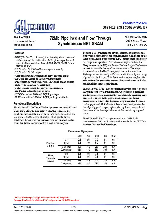
GS8640Z18/36T-300/250/200/16772Mb Pipelined and Flow ThroughSynchronous NBT SRAM 300 MHz –167 MHz 2.5 V or 3.3 V V DD 2.5 V or 3.3 V I/O100-Pin TQFP Commercial Temp Industrial Temp Features• NBT (No Bus Turn Around) functionality allows zero wait read-write-read bus utilization; Fully pin-compatible with both pipelined and flow through NtRAM™, NoBL™ and ZBT™ SRAMs• 2.5 V or 3.3 V +10%/–10% core power supply • 2.5 V or 3.3 V I/O supply• User-configurable Pipeline and Flow Through mode • LBO pin for Linear or Interleave Burst mode• Pin compatible with 4Mb, 9Mb, 18Mb and 36Mb devices • Byte write operation (9-bit Bytes)• 3 chip enable signals for easy depth expansion • ZZ Pin for automatic power-down• JEDEC-standard 100-lead TQFP package• RoHS-compliant 100-lead TQFP package availableFunctional DescriptionThe GS8640Z18/36T is a 72Mbit Synchronous Static SRAM. GSI's NBT SRAMs, like ZBT, NtRAM, NoBL or other pipelined read/double late write or flow through read/single late write SRAMs, allow utilization of all available bus bandwidth by eliminating the need to insert deselect cycles when the device is switched from read to write cycles.Because it is a synchronous device, address, data inputs, and read/ write control inputs are captured on the rising edge of the input clock. Burst order control (LBO) must be tied to a power rail for proper operation. Asynchronous inputs include the Sleep mode enable (ZZ) and Output Enable. Output Enable can be used to override the synchronous control of the output drivers and turn the RAM's output drivers off at any time. Write cycles are internally self-timed and initiated by the rising edge of the clock input. This feature eliminates complex off-chip write pulse generation required by asynchronous SRAMs and simplifies input signal timing.The GS8640Z18/36T may be configured by the user to operate in Pipeline or Flow Through mode. Operating as a pipelined synchronous device, meaning that in addition to the rising edge triggered registers that capture input signals, the deviceincorporates a rising-edge-triggered output register. For read cycles, pipelined SRAM output data is temporarily stored by the edge triggered output register during the access cycle and then released to the output drivers at the next rising edge of clock.The GS8640Z18/36T is implemented with GSI's highperformance CMOS technology and is available in a JEDEC-standard 100-pin TQFP package.Parameter Synopsis-300-250-200-167Unit Pipeline 3-1-1-1t KQ tCycle 2.33.3 2.54.0 3.05.0 3.56.0ns ns (x18)Curr (x32/x36)480410350305mA Flow Through 2-1-1-1t KQ tCycle 5.55.5 6.56.57.57.58.08.0ns ns (x18)Curr (x32/x36)330280250240mA*All GSI Technology packages are at least 5/6 RoHS compliant.Packages listed with the additional “G” designator are 6/6 RoHS compliant.807978777675747372717069686766656463626160595857565554535251123456789101112131415161718192021222324252627282930V DDQ V SS DQ B DQ B V SS V DDQ DQ B DQ B FT V DD V DD V SS DQ B DQ B V DDQ V SS DQ B DQ B DQP BV SS V DDQ V DDQ V SS DQ A DQ A V SS V DDQ DQ A DQ A V SS NC V DD ZZ DQ A DQ A V DDQ V SS DQ A DQ A V SS V DDQ L B O A A A A A 1A 0N C N C V S SV D DA A A A A A A AA A E 1E 2 N C N C B BB AE 3C K W C K E VD DV S SG A D V A A A AA 2M x 18Top View DQP A A NC NC NC NC NC NC NC NCNC NC NC NC NC NC NCNC NC 100999897969594939291908988878685848382813132333435363738394041424344454647484950GS8640Z18/36T-300/250/200/167GS8640Z18T Pinout807978777675747372717069686766656463626160595857565554535251123456789101112131415161718192021222324252627282930V DDQ V SS DQ C DQ C V SS V DDQ DQ C DQ C FT V DD V DD V SS DQ D DQ D V DDQ V SS DQ D DQ D DQ D V SS V DDQ V DDQ V SS DQ B DQ B V SS V DDQ DQ B DQ B V SS NC V DD ZZ DQ A DQ A V DDQ V SS DQ A DQ A V SS V DDQ L B O A A A A A 1A 0N C N C V S SV D DA A A A A A A AA A E 1E 2 B DB CB BB AE 3C K W C K E VD DV S SG A D V A A A AA 1M x 36Top View DQB DQP B DQ B DQ B DQ B DQ A DQ A DQ A DQ A DQP ADQ C DQ C DQ C DQ D DQ D DQ D DQP DDQ C DQP C 100999897969594939291908988878685848382813132333435363738394041424344454647484950GS8640Z18/36T-300/250/200/167GS8640Z36T PinoutTQFP Pin DescriptionsSymbolTypeDescriptionA 0, A 1In Burst Address Inputs; Preload the burst counterA In Address Inputs CK In Clock Input SignalB A In Byte Write signal for data inputs DQ A1-DQ A9; active low B B In Byte Write signal for data inputs DQ B1-DQ B9; active low BC In Byte Write signal for data inputs DQ C1-DQ C9; active low BD In Byte Write signal for data inputs DQ D1-DQ D9; active lowW In Write Enable; active low E 1In Chip Enable; active lowE 2In Chip Enable; Active High. For self decoded depth expansion E 3In Chip Enable; Active Low. For self decoded depth expansionG In Output Enable; active lowADV In Advance/Load; Burst address counter control pinCKE In Clock Input Buffer Enable; active low DQ A I/O Byte A Data Input and Output pins DQ B I/O Byte B Data Input and Output pins DQ C I/O Byte C Data Input and Output pins DQ D I/O Byte D Data Input and Output pins ZZ In Power down control; active high FT In Pipeline/Flow Through Mode Control; active lowLBO In Linear Burst Order; active lowV DD In Core power supplyV SS In GroundV DDQ In Output driver power supplyNC—No ConnectGS8640Z18/36T-300/250/200/167KS A 1S A 0B u r s t Co u nt e rL B OA D VM e m o r y A r r a yE 3E 2E 1GWB DB CB BB AC KC K ED QF TD Q a –D Q nKS A 1’S A 0’D QM a t c hW r i t e A d d r e s sR e g i s t e r 2W r i t e A d d r e s sR e g i s t e r 1W r i t e D a t aR e g i s t e r 2W r i t e D a t aR e g i s t e r 1KKKKKKS e n s e A m p sW r i t e D r i v e r sR e a d , W r i t e a n dD a t a C o h e r e n c yC o n t r o l L o g i cF TA 0–A nGS8640Z18/36T-300/250/200/167GS8640Z18/36 NBT SRAM Functional Block DiagramGS8640Z18/36T-300/250/200/167Functional DetailsClockingDeassertion of the Clock Enable (CKE) input blocks the Clock input from reaching the RAM's internal circuits. It may be used to suspend RAM operations. Failure to observe Clock Enable set-up or hold requirements will result in erratic operation.Pipeline Mode Read and Write OperationsAll inputs (with the exception of Output Enable, Linear Burst Order and Sleep) are synchronized to rising clock edges. Single cycle read and write operations must be initiated with the Advance/Load pin (ADV) held low, in order to load the new address. Device activation is accomplished by asserting all three of the Chip Enable inputs (E 1, E 2 and E 3). Deassertion of any one of the Enable inputs will deactivate the device. Function W B A B B B C B D Read H X X X X Write Byte “a”L L H H H Write Byte “b”L H L H H Write Byte “c”L H H L H Write Byte “d”L H H H L Write all Bytes L L L L L Write Abort/NOPLHHHHRead operation is initiated when the following conditions are satisfied at the rising edge of clock: CKE is asserted Low, all three chip enables (E 1, E 2, and E 3) are active, the write enable input signals W is deasserted high, and ADV is asserted low. The address presented to the address inputs is latched in to address register and presented to the memory core and control logic. The control logic determines that a read access is in progress and allows the requested data to propagate to the input of the output register. At the next rising edge of clock the read data is allowed to propagate through the output register and onto the output pins.Write operation occurs when the RAM is selected, CKE is active, and the Write input is sampled low at the rising edge of clock. The Byte Write Enable inputs (B A , B B , B C, & B D ) determine which bytes will be written. All or none may be activated. A write cycle with no Byte Write inputs active is a no-op cycle. The pipelined NBT SRAM provides double late write functionality,matching the write command versus data pipeline length (2 cycles) to the read command versus data pipeline length (2 cycles). At the first rising edge of clock, Enable, Write, Byte Write(s), and Address are registered. The Data In associated with that address is required at the third rising edge of clock.Flow Through Mode Read and Write OperationsOperation of the RAM in Flow Through mode is very similar to operations in Pipeline mode. Activation of a Read Cycle and the use of the Burst Address Counter is identical. In Flow Through mode the device may begin driving out new data immediately after new address are clocked into the RAM, rather than holding new data until the following (second) clock edge. Therefore, in Flow Through mode the read pipeline is one cycle shorter than in Pipeline mode.Write operations are initiated in the same way, but differ in that the write pipeline is one cycle shorter as well, preserving the ability to turn the bus from reads to writes without inserting any dead cycles. While the pipelined NBT RAMs implement a double late write protocol, in Flow Through mode a single late write protocol mode is observed. Therefore, in Flow Through mode, address and control are registered on the first rising edge of clock and data in is required at the data input pins at the second rising edge of clock.Synchronous Truth TableOperationType Address CK CKE ADV W Bx E 1E 2E 3G ZZDQNotesRead Cycle, Begin Burst R External L-H L L H X L H L L L Q Read Cycle, Continue Burst B Next L-H L H X X X X X L L Q 1,10NOP/Read, Begin Burst R External L-H L L H X L H L H L High-Z 2Dummy Read, Continue Burst B Next L-H L H X X X X X H L High-Z 1,2,10Write Cycle, Begin Burst W External L-H L L L L L H L X L D 3Write Cycle, Continue Burst B Next L-H L H X L X X X X L D1,3,10Write Abort, Continue Burst B Next L-H L H X H X X X X L High-Z 1,2,3,10Deselect Cycle, Power Down D None L-H L L X X H X X X L High-Z Deselect Cycle, Power Down D None L-H L L X X X X H X L High-Z Deselect Cycle, Power Down D None L-H L L X X X L X X L High-Z Deselect Cycle D None L-H L L L H L H L X L High-Z 1Deselect Cycle, Continue DNone L-H L H X X X X X X L High-Z 1Sleep ModeNone X X X X X X X X X H High-Z Clock Edge Ignore, StallCurrentL-HHXXXXXXXL-4Notes:1.Continue Burst cycles, whether read or write, use the same control inputs. A Deselect continue cycle can only be entered into if a Dese-lect cycle is executed first.2.Dummy Read and Write abort can be considered NOPs because the SRAM performs no operation. A Write abort occurs when the Wpin is sampled low but no Byte Write pins are active so no write operation is performed.3.G can be wired low to minimize the number of control signals provided to the SRAM. Output drivers will automatically turn off duringwrite cycles.4.If CKE High occurs during a pipelined read cycle, the DQ bus will remain active (Low Z). If CKE High occurs during a write cycle, the buswill remain in High Z.5. X = Don’t Care; H = Logic High; L = Logic Low; Bx = High = All Byte Write signals are high; Bx = Low = One or more Byte/Writesignals are Low6.All inputs, except G and ZZ must meet setup and hold times of rising clock edge.7.Wait states can be inserted by setting CKE high.8.This device contains circuitry that ensures all outputs are in High Z during power-up.9. A 2-bit burst counter is incorporated.10.The address counter is incriminated for all Burst continue cycles.GS8640Z18/36T-300/250/200/167GS8640Z18/36T-300/250/200/167DeselectNew ReadNew WriteBurst ReadBurst WriteWRBRBWDDBBWRD BWRDDCurrent State (n)Next State (n+1)TransitionƒInput Command CodeKeyNotes:1. The Hold command (CKE Low) is notshown because it prevents any state change.2. W, R, B and D represent input commandcodes ,as indicated in the Synchronous Truth Table.Clock (CK)CommandCurrent StateNext Stateƒnn+1n+2n+3ƒƒƒCurrent State and Next State Definition for Pipeline and Flow Through Read/Write Control State DiagramWRPipeline and Flow Through Read Write Control State DiagramGS8640Z18/36T-300/250/200/167IntermediateIntermediateIntermediateIntermediateIntermediateIntermediateHigh Z (Data In)Data Out (Q Valid)High Z B W B R B DRW RWDDCurrent State (n)TransitionƒInput Command CodeKeyTransitionIntermediate State (N+1)Notes:1. The Hold command (CKE Low) is notshown because it prevents any state change.2. W, R, B, and D represent input command codes as indicated in the Truth Tables.Clock (CK)CommandCurrent StateIntermediate ƒn n+1n+2n+3ƒƒƒCurrent State and Next State Definition for Pipeline Mode Data I/O State DiagramNext StateStatePipeline Mode Data I/O State DiagramGS8640Z18/36T-300/250/200/167High Z (Data In)Data Out (Q Valid)High Z B W B R B DRW RWDDCurrent State (n)Next State (n+1)TransitionƒInput Command CodeKeyNotes1. The Hold command (CKE Low) is notshown because it prevents any state change.2. W, R, B and D represent input command codes as indicated in the Truth Tables.Clock (CK)CommandCurrent StateNext Stateƒnn+1n+2n+3ƒƒƒCurrent State and Next State Definition for: Pipeline and Flow Through Read Write Control State DiagramFlow Through Mode Data I/O State DiagramGS8640Z18/36T-300/250/200/167Burst CyclesAlthough NBT RAMs are designed to sustain 100% bus bandwidth by eliminating turnaround cycle when there is transition from read to write, multiple back-to-back reads or writes may also be performed. NBT SRAMs provide an on-chip burst address generator that can be utilized, if desired, to further simplify burst read or write implementations. The ADV control pin, when driven high, commands the SRAM to advance the internal address counter and use the counter generated address to read or write the SRAM. The starting address for the first cycle in a burst cycle series is loaded into the SRAM by driving the ADV pin low, into Load mode.Burst OrderThe burst address counter wraps around to its initial state after four addresses (the loaded address and three more) have beenaccessed. The burst sequence is determined by the state of the Linear Burst Order pin (LBO). When this pin is low, a linear burst sequence is selected. When the RAM is installed with the LBO pin tied high, Interleaved burst sequence is selected. See the tables below for details.Mode Pin FunctionsMode NamePin NameStateFunctionBurst Order Control LBO L Linear Burst H Interleaved Burst Output Register Control FT L Flow Through H or NC Pipeline Power Down Control ZZ L or NC Active H Standby, I DD = I SB Single/Dual Cycle Deselect Control SCD L Dual Cycle Deselect H or NC Single Cycle Deselect FLXDrive Output Impedance ControlZQ L High Drive (Low Impedance)H or NC Low Drive (High Impedance)9th Bit EnablePEL Activate DQPx I/Os (x18/x3672 mode)H or NCDeactivate DQPx I/Os (x16/x3272 mode)Note:There is a are pull-up devices on the ZQ, SCD, and FT pins and a pull-down device on the ZZ pin, so those this input pins can be unconnected and the chip will operate in the default states as specified in the above tables.Note:The burst counter wraps to initial state on the 5th clock.Note:The burst counter wraps to initial state on the 5th clock.Linear Burst SequenceA[1:0]A[1:0]A[1:0]A[1:0]1st address 000110112nd address 011011003rd address 101100014th address11000110Interleaved Burst SequenceA[1:0]A[1:0]A[1:0]A[1:0]1st address 000110112nd address 010011103rd address 101100014th address11100100GS8640Z18/36T-300/250/200/167Burst Counter SequencesBPR 1999.05.18GS8640Z18/36T-300/250/200/167Sleep ModeDuring normal operation, ZZ must be pulled low, either by the user or by it’s internal pull down resistor. When ZZ is pulled high, the SRAM will enter a Power Sleep mode after 2 cycles. At this time, internal state of the SRAM is preserved. When ZZ returns to low, the SRAM operates normally after 2 cycles of wake up time.Sleep mode is a low current, power-down mode in which the device is deselected and current is reduced to I SB 2. The duration of Sleep mode is dictated by the length of time the ZZ is in a high state. After entering Sleep mode, all inputs except ZZ become disabled and all outputs go to High-Z The ZZ pin is an asynchronous, active high input that causes the device to enter Sleep mode. When the ZZ pin is driven high, I SB 2 is guaranteed after the time tZZI is met. Because ZZ is an asynchronous input, pending operations or operations in progress may not be properly completed if ZZ is asserted. Therefore, Sleep mode must not be initiated until valid pending operations are completed. Similarly, when exiting Sleep mode during tZZR, only a deselect or read commands may be applied while the SRAM is recovering from Sleep mode.Sleep Mode Timing DiagramtZZRtZZHtZZStKLtKHtKCCKZZDesigning for CompatibilityThe GSI NBT SRAMs offer users a configurable selection between Flow Through mode and Pipeline mode via the FT signal found on Pin 14. Not all vendors offer this option, however most mark Pin 14 as V DD or V DDQ on pipelined parts and V SS on flow through parts. GSI NBT SRAMs are fully compatible with these sockets.Absolute Maximum Ratings(All voltages reference to V SS )SymbolDescriptionValueUnitV DD Voltage on V DD Pins –0.5 to 4.6V V DDQ Voltage in V DDQ Pins –0.5 to 4.6V V I/O Voltage on I/O Pins –0.5 to V DDQ +0.5 (≤ 4.6 V max.)V V IN Voltage on Other Input Pins –0.5 to V DD +0.5 (≤ 4.6 V max.)V I IN Input Current on Any Pin +/–20mA I OUT Output Current on Any I/O Pin +/–20mA P D Package Power Dissipation 1.5WT STG Storage Temperature –55 to 125o C T BIASTemperature Under Bias–55 to 125oCGS8640Z18/36T-300/250/200/167Note:Permanent damage to the device may occur if the Absolute Maximum Ratings are exceeded. Operation should be restricted to Recommended Operating Conditions. Exposure to conditions exceeding the Absolute Maximum Ratings, for an extended period of time, may affect reliability of this component. Power Supply Voltage RangesParameterSymbolMin.Typ.Max.UnitNotes3.3 V Supply Voltage V DD3 3.0 3.3 3.6V 2.5 V Supply Voltage V DD2 2.3 2.5 2.7V 3.3 V V DDQ I/O Supply Voltage V DDQ3 3.0 3.3 3.6V 2.5 V V DDQ I/O Supply VoltageV DDQ22.32.52.7VNotes:1.The part numbers of Industrial Temperature Range versions end the character “I”. Unless otherwise noted, all performance specifica-tions quoted are evaluated for worst case in the temperature range marked on the device.2.Input Under/overshoot voltage must be –2 V > Vi < V DDn +2 V not to exceed 4.6 V maximum, with a pulse width not to exceed 20% tKC.GS8640Z18/36T-300/250/200/167V DDQ3 Range Logic LevelsParameterSymbolMin.Typ.Max.UnitNotesV DD Input High Voltage V IH 2.0—V DD + 0.3V 1V DD Input Low Voltage V IL –0.3—0.8V 1V DDQ I/O Input High Voltage V IHQ 2.0—V DDQ + 0.3V 1,3V DDQ I/O Input Low VoltageV ILQ–0.3—0.8V1,3Notes:1.The part numbers of Industrial Temperature Range versions end the character “I”. Unless otherwise noted, all performance specifica-tions quoted are evaluated for worst case in the temperature range marked on the device.2.Input Under/overshoot voltage must be –2 V > Vi < V DDn +2 V not to exceed 4.6 V maximum, with a pulse width not to exceed 20% tKC.3.V IHQ (max) is voltage on V DDQ pins plus 0.3 V.V DDQ2 Range Logic LevelsParameterSymbolMin.Typ.Max.UnitNotesV DD Input High Voltage V IH 0.6*V DD —V DD + 0.3V 1V DD Input Low Voltage V IL –0.3—0.3*V DD V 1V DDQ I/O Input High Voltage V IHQ 0.6*V DD —V DDQ + 0.3V 1,3V DDQ I/O Input Low VoltageV ILQ–0.3—0.3*V DDV1,3Notes:1.The part numbers of Industrial Temperature Range versions end the character “I”. Unless otherwise noted, all performance specifica-tions quoted are evaluated for worst case in the temperature range marked on the device.2.Input Under/overshoot voltage must be –2 V > Vi < V DDn +2 V not to exceed 4.6 V maximum, with a pulse width not to exceed 20% tKC.3.V IHQ (max) is voltage on V DDQ pins plus 0.3 V.Recommended Operating TemperaturesParameterSymbolMin.Typ.Max.UnitNotesAmbient Temperature (Commercial Range Versions)T A 02570°C 2Ambient Temperature (Industrial Range Versions)T A–402585°C2Notes:1.The part numbers of Industrial Temperature Range versions end the character “I”. Unless otherwise noted, all performance specifica-tions quoted are evaluated for worst case in the temperature range marked on the device.2.Input Under/overshoot voltage must be –2 V > Vi < V DDn +2 V not to exceed 4.6 V maximum, with a pulse width not to exceed 20% tKC.GS8640Z18/36T-300/250/200/16720% tKCV SS – 2.0 V50%V SS V IHUndershoot Measurement and TimingOvershoot Measurement and Timing20% tKCV DD + 2.0 V50%V DDV ILCapacitanceo C, f = 1 MH Z , V DD ParameterSymbolTest conditionsTyp.Max.UnitInput Capacitance C IN V IN = 0 V 45pF Input/Output Capacitance C I/OV OUT = 0 V67pFNote:These parameters are sample tested.AC Test ConditionsParameterConditionsInput high level V DD – 0.2 V Input low level 0.2 V Input slew rate 1 V/ns Input reference level V DDQ /2Output reference levelV DDQ /2Output loadFig. 1Notes:1.Include scope and jig capacitance.2.Test conditions as specified with output loading as shown in Fig. 1unless otherwise noted.3.Device is deselected as defined by the Truth Table.DQV DDQ/250Ω30pF *Output Load 1* Distributed Test Jig Capacitance(T A = 25= 2.5 V)DC Electrical CharacteristicsParameterSymbolTest ConditionsMinMaxInput Leakage Current (except mode pins)I IL V IN = 0 to V DD –2 uA 2 uA ZZInput CurrentI IN1V DD ≥ V IN ≥ V IH 0 V ≤ V IN ≤ V IH–1 uA –1 uA 1 uA 100 uA Output Leakage Current (x36/x72)I OL Output Disable, V OUT = 0 to V DD –1 uA 1 uA Output Leakage Current (x18)I OL Output Disable, V OUT = 0 to V DD –1 uA 1 uA Output High Voltage V OH2I OH = –8 mA, V DDQ = 2.375 V 1.7 V —Output High Voltage V OH3I OH = –8 mA, V DDQ = 3.135 V2.4 V —Output Low VoltageV OLI OL = 8 mA—0.4 VGS8640Z18/36T-300/250/200/167Operating CurrentsParameterTest ConditionsModeSymbol-300-250-200-167Unit0to 70°C –40 to 85°C 0to 70°C –40 to 85°C 0to 70°C –40to 85°C 0 to 70°C –40to 85°C Operating CurrentDevice Selected; All other inputs ≥V IH o r ≤ V IL Output open(x32/x36)Pipeline I DD I DDQ 4206044060360503805031040330402703529035mA Flow Through I DD I DDQ 3003032030255252752523020250202202024020mA (x18)PipelineI DD I DDQ 3703039030315253352527020290202402026020mA Flow Through I DD I DDQ 2701529015230152501520515225151951521515mA Standby Current ZZ ≥ V DD – 0.2 V —PipelineI SB 100120100120100120100120mA Flow Through I SB 100120100120100120100120mA Deselect CurrentDevice Deselected; All other inputs ≥ V IH or ≤ V IL—Pipeline I DD 150165140155130146125140mA Flow ThroughI DD135150125140120135120135mAGS8640Z18/36T-300/250/200/167Notes:1.I DD and I DDQ apply to any combination of V DD3, V DD2, V DDQ3, and V DDQ2 operation.2.All parameters listed are worst case scenario.AC Electrical CharacteristicsParameter Symbol -300-250-200-167Unit Min Max MinMax MinMax MinMax PipelineClock Cycle Time tKC 3.3— 4.0— 5.0— 6.0—ns Clock to Output ValidtKQ — 2.3— 2.5— 3.0— 3.5ns Clock to Output Invalid tKQX 1.5— 1.5— 1.5— 1.5—ns Clock to Output in Low-ZtLZ 1 1.5— 1.5— 1.5— 1.5—ns Setup time tS 1.1— 1.2— 1.4— 1.5—ns Hold time tH 0.1—0.2—0.4—0.5—ns Flow ThroughClock Cycle Time tKC 5.5— 6.5—7.5—8.0—ns Clock to Output ValidtKQ — 5.5— 6.5—7.5—8.0ns Clock to Output Invalid tKQX 3.0— 3.0— 3.0— 3.0—ns Clock to Output in Low-ZtLZ 1 3.0— 3.0— 3.0— 3.0—ns Setup time tS 1.5— 1.5— 1.5— 1.5—ns Hold time tH 0.5—0.5—0.5—0.5—ns Clock HIGH Time tKH 1.0— 1.3— 1.3— 1.3—ns Clock LOW Time tKL 1.2— 1.5— 1.5— 1.5—ns Clock to Output inHigh-Z tHZ 1 1.5 2.3 1.5 2.5 1.5 3.0 1.5 3.0ns G to Output Valid tOE — 2.3— 2.5— 3.0— 3.5ns G to output in Low-Z tOLZ 10—0—0—0—ns G to output in High-Z tOHZ 1— 2.3— 2.5— 3.0— 3.0ns ZZ setup time tZZS 25—5—5—5—ns ZZ hold time tZZH 21—1—1—1—ns ZZ recoverytZZR20—20—20—20—nsGS8640Z18/36T-300/250/200/167Notes:1.These parameters are sampled and are not 100% tested.2.ZZ is an asynchronous signal. However, in order to be recognized on any given clock cycle, ZZ must meet the specified setup and holdtimes as specified above.GS8640Z18/36T-300/250/200/167Pipeline Mode Timing (NBT)Write ARead BSuspend Read CWrite Dwriteno-opRead EDeselecttHZtKQXtKQtLZ tH tStHtStH tStH tStH tStH tStH tStH tStKCtKLtKHA B C D ED(A)D(D)Q(E)Q(B)Q(C)CKA CKEE*ADVWBnDQGS8640Z18/36T-300/250/200/167Flow Through Mode Timing (NBT)Write AWrite BWrite B+1Read CCont Read D Write E Read F Write GD(A)D(B)D(B+1)Q(C)Q(D)D(E)Q(F)D(G)tOLZ tOEtOHZtKQXtKQtLZtHZtKQX tKQ tLZtHtStHtStHtStHtStHtStHtStHtStKCtKLtKHABCDEFG*Note: E = High(False) if E1 = 1 or E2 = 0 or E3 = 1CKCKEEADVWBnA0–AnDQGGS8640Z18/36T-300/250/200/167TQFP Package Drawing (Package T) D1DE1EPin 1be cLL1A2A1YθNotes:1.All dimensions are in millimeters (mm).2.Package width and length do not include mold protrusion.SymbolDescriptionMin.Nom.MaxA1Standoff 0.050.100.15A2Body Thickness 1.35 1.40 1.45b Lead Width 0.200.300.40c Lead Thickness 0.09—0.20D Terminal Dimension 21.922.022.1D1Package Body 19.920.020.1E Terminal Dimension 15.916.016.1E1Package Body 13.914.014.1e Lead Pitch —0.65—L Foot Length 0.450.600.75L1Lead Length —1.00—Y Coplanarity 0.10θLead Angle0°—7°GS8640Z18/36T-300/250/200/167Ordering Information —GSI NBT Synchronous SRAM OrgPart Number1Type2PackageSpeed 3(M Hz/ns)T A 4Status4M x 18GS8640Z18T-300NBT Pipeline/Flow Through TQFP 300/5.5C 4M x 18GS8640Z18T-250NBT Pipeline/Flow Through TQFP 250/6.5C 4M x 18GS8640Z18T-200NBT Pipeline/Flow Through TQFP 200/7.5C 4M x 18GS8640Z18T-167NBT Pipeline/Flow Through TQFP 167/8C 2M x 36GS8640Z36T-300NBT Pipeline/Flow Through TQFP 300/5.5C 2M x 36GS8640Z36T-250NBT Pipeline/Flow Through TQFP 250/6.5C 2M x 36GS8640Z36T-200NBT Pipeline/Flow Through TQFP 200/7.5C 2M x 36GS8640Z36T-167NBT Pipeline/Flow Through TQFP 167/8C 4M x 18GS8640Z18T-300I NBT Pipeline/Flow Through TQFP 300/5.5I 4M x 18GS8640Z18T-250I NBT Pipeline/Flow Through TQFP 250/6.5I 4M x 18GS8640Z18T-200I NBT Pipeline/Flow Through TQFP 200/7.5I 4M x 18GS8640Z18T-167I NBT Pipeline/Flow Through TQFP 167/8I 2M x 36GS8640Z36T-300I NBT Pipeline/Flow Through TQFP 300/5.5I 2M x 36GS8640Z36T-250I NBT Pipeline/Flow Through TQFP 250/6.5I 2M x 36GS8640Z36T-200I NBT Pipeline/Flow Through TQFP 200/7.5I 2M x 36GS8640Z36T-167I NBT Pipeline/Flow Through TQFP167/8I 4M x 18GS8640Z18GT-300NBT Pipeline/Flow Through RoHS-compliant TQFP 300/5.5C 4M x 18GS8640Z18GT-250NBT Pipeline/Flow Through RoHS-compliant TQFP 250/6.5C 4M x 18GS8640Z18GT-200NBT Pipeline/Flow Through RoHS-compliant TQFP 200/7.5C 4M x 18GS8640Z18GT-167NBT Pipeline/Flow Through RoHS-compliant TQFP 167/8C 2M x 36GS8640Z36GT-300NBT Pipeline/Flow Through RoHS-compliant TQFP 300/5.5C 2M x 36GS8640Z36GT-250NBT Pipeline/Flow ThroughRoHS-compliant TQFP250/6.5CNotes:1.Customers requiring delivery in Tape and Reel should add the character “T” to the end of the part number. Example: GS8640Z36T-167IT.2.All GSI Technology packages are at least 5/6 RoHS compliant. Packages listed with the additional “G” designator are 6/6 RoHS compliant.3.The speed column indicates the cycle frequency (MHz) of the device in Pipeline mode and the latency (ns) in Flow Through mode. Eachdevice is Pipeline/Flow Through mode-selectable by the user.4.T A = C = Commercial Temperature Range. T A = I = Industrial Temperature Range.5.GSI offers other versions this type of device in many different configurations and with a variety of different features, only some of which arecovered in this data sheet. See the GSI Technology web site () for a complete listing of current offerings。