Draeger德尔格目前先进麻醉机技术介绍
- 格式:ppt
- 大小:685.50 KB
- 文档页数:22
Drager呼吸机选项设定
Drager呼吸机是一种常用的医疗设备,用于支持和维持患者的
呼吸功能。
在使用Drager呼吸机时,正确的选项设定是非常重要的,因为它可以帮助医生根据患者的具体情况提供最合适的治疗。
以下是Drager呼吸机的几个重要选项设定:
1. 模式选择:Drager呼吸机提供了不同的呼吸模式供选择,包
括辅助控制通气模式(ACV)、同步间歇强制通气模式(SIMV)
和压力支持通气模式(PSV)等。
医生需要根据患者的病情和需要
选择适合的呼吸模式。
2. 呼吸频率:呼吸频率是指每分钟进行呼吸的次数。
医生可以
根据患者的肺功能和呼吸需求来设定呼吸频率。
3. 潮气量:潮气量是指每次呼吸中吸入或排出的空气量。
医生
需要根据患者的身体状况和肺功能来设定潮气量。
4. 吸气流速:吸气流速是指呼气末到吸气末的空气流动速度。
医生可以根据患者的需要调整吸气流速,以提供合适的气流支持。
5. 氧浓度:氧浓度是指给予患者氧气的浓度。
医生可以根据患
者的需要设定合适的氧浓度,以确保患者获得足够的氧供应。
6. 呼气末正压(PEEP):PEEP是在呼气末保持正压的情况下
进行呼吸。
医生可以根据患者的需要设定合适的PEEP,以增加肺
泡内气体的稳定性和气体交换效果。
在设定Drager呼吸机的选项时,医生需要综合考虑患者的病情、呼吸需求和肺功能等因素。
正确的选项设定可以帮助医生提供有效
的呼吸支持,并最大程度地改善患者的生活质量。
以上是关于Drager呼吸机选项设定的简要介绍。

Protocol DefinitionDräger RS 232 MEDIBUSRevision Level 6.00 WARNING!Strictly follow the Instructions for Use.Any use of the software protocolrequires full understanding and strictobservation of these instructions. Thesoftware protocol is only to be used forpurposes specified here.Contents2Dräger RS 232MEDIBUSContentsIntended Use . . . . . . . . . . . . . . . . . . . . . . . . . .3MEDIBUS Introduction . . . . . . . . . . . . . . . . . .4Initializing Communication . . . . . . . . . . . . . . . .4Terminating Communication. . . . . . . . . . . . . . .5Time-Out. . . . . . . . . . . . . . . . . . . . . . . . . . . . . .5Allowable Characters . . . . . . . . . . . . . . . . . . . .5Software Handshaking. . . . . . . . . . . . . . . . . . .6Suspending data transmission. . . . . . . . . . . . .6Resuming data transmission . . . . . . . . . . . . . .6Aborting data transmission. . . . . . . . . . . . . . . .6MEDIBUS Commands . . . . . . . . . . . . . . . . . .7Structure of Commands . . . . . . . . . . . . . . . . . .7Command Codes . . . . . . . . . . . . . . . . . . . . . . .8Request Trend Data Command . . . . . . . . . . . .11MEDIBUS Responses . . . . . . . . . . . . . . . . . . .12Structure of Responses . . . . . . . . . . . . . . . . . .12Responding to Control Commands and unknown Commands. . . . . . . . . . . . . . . . . . . . . . . . . . . .13Responding to corrupt Commands. . . . . . . . . .13Responding to Data Request Commands . . . .14MEDIBUS Device Extension forInfusion Pumps . . . . . . . . . . . . . . . . . . . . . . . .22Introduction. . . . . . . . . . . . . . . . . . . . . . . . . . . .22MEDIBUS Device Extension Protocol Concept 22Infusion Pump Commands. . . . . . . . . . . . . . . .23Infusion Pump Communication Life Cycle . . . .24Request Infusion Pump Configuration . . . . . . .25Infusion Pump Configuration ChangedCommand. . . . . . . . . . . . . . . . . . . . . . . . . . . . .26Infusion Pump Data Update Commands . . . . .27MEDIBUS Realtime-Extension Introduction30Time-Out. . . . . . . . . . . . . . . . . . . . . . . . . . . . . .30Allowable Characters for RealtimeTransmission . . . . . . . . . . . . . . . . . . . . . . . . . .31MEDIBUS Realtime-Extension Commands .33Command Codes . . . . . . . . . . . . . . . . . . . . . . .33Request Realtime Configuration Command. . .33Configure Realtime Transmission Command . 34Realtime Configuration Changed Command. . 34MEDIBUS Realtime-Extension Responses . 35Realtime Configuration Response. . . . . . . . . . 35MEDIBUS Realtime-Extension Realtime-Data Records . . . . . . . . . . . . . . . . . . . . . . . . . . . . . 36Structure of Realtime-Data Records . . . . . . . . 36Sync-Commands. . . . . . . . . . . . . . . . . . . . . . . 38Appendix . . . . . . . . . . . . . . . . . . . . . . . . . . . . 40MEDIBUS-Life-Cycle. . . . . . . . . . . . . . . . . . . . 40MEDIBUS Realtime-Extension Life-Cycle. . . . 42ASCII HEX Format . . . . . . . . . . . . . . . . . . . . . 45MEDIBUS example 1 . . . . . . . . . . . . . . . . . . . 46MEDIBUS example 2 . . . . . . . . . . . . . . . . . . . 47MEDIBUS example 3 . . . . . . . . . . . . . . . . . . . 48MEDIBUS example 4 . . . . . . . . . . . . . . . . . . . 49MEDIBUS example 5 . . . . . . . . . . . . . . . . . . . 50MEDIBUS example 6 . . . . . . . . . . . . . . . . . . . 51Frequently Asked Questions. . . . . . . . . . . . . . 55Logbook of Changes. . . . . . . . . . . . . . . . . . . . 58Table of used ASCII-Codes. . . . . . . . . . . . . . .59Intended Use Intended UseMEDIBUS is a software protocol intended to beused for exchanging data between a Dräger medi-cal device and external medical or non-medicaldevices via RS 232 interfaces.WARNINGData transferred via MEDIBUS interfaces are forinformation only and are not intended as a basisfor diagnosis or therapy decisions.MEDIBUS consists of two independent softwareprotocols one for the transmission of "slow" andone for the transmission of "fast" data."Slow" data:Generated or updated in intervals of the magnitudeof seconds. This part is called MEDIBUS."Fast" data:Intended for the transmission of e. g. realtimecurves. This part of MEDIBUS is called the "Real-time-Extension".This manual contains a general description of theprotocol including formats of commands andresponses.For device dependent descriptions of supportedcommands and data sets, port hardware and con-figurations for Dräger devices please refer to theindividual device-specific MEDIBUS documenta-tion.Dräger RS232MEDIBUS3MEDIBUS IntroductionMEDIBUS IntroductionThe MEDIBUS protocol distinguishes two basictypes of messages:–commands–responses.A command is transmitted by one device to requestdata from the other device or to control its function.A response is transmitted by one device uponreceipt of a command from the other device.Responses may contain embedded commands.Initializing Communication(refer to MEDIBUS-life-cyle-diagram, see page40)–To initialize communication or to restart commu-nication after a time-out, a device must send the"Initialize Communications Command" ICC.Refer to section "Control commands" for the for-mat of commands.– A device considers communication initializedafter having received either a response to atransmitted ICC or an ICC from the otherdevice. Refer to section "Responding to com-mands" for the format of responses.–Commands embedded in a response to an ICCare disregarded.4Dräger RS232MEDIBUSMEDIBUS Introduction Terminating Communication–To stop the communication the "STOP" com-mand has to be sent.–The command echo has to be checked to makesure the "Stop Communication" command hasbeen received correctly. Further commandsfrom the linked device may be ignored until thecommunication has been reinitialized.Time-Out–Any pause in the data flow exceeding 3 sec-onds leads to a time-out, terminating the com-munication link. To resume communication aftera time-out, the device must re-initialize commu-nication by transmitting an ICC command (seesection "Initializing communication", page4).Whenever a device receives an ICC command,it must send a response to it (see section"Responses", page12).–After receiving a command the device has tosend a complete response within 10 seconds.–If there is no need for sending commands orresponses the "NOP"–command has to be sentin 2-second-intervals to keep the communica-tion alive.Allowable Characters–Printable ASCII characters.–Control characters defined in this Instructionsfor Use.Dräger RS232MEDIBUS5MEDIBUS Introduction6Dräger RS 232MEDIBUSSoftware HandshakingSome control characters can be sent at any time to control the flow of data. They do not require responses.Suspending data transmission–If a receiving device wants the transmitting device to suspend transmission, the ASCII "DC1" character (11H) must be sent.–Upon receipt of this character, the sending device will suspend any transmission immedi-ately until it receives the ASCII "DC3" character.Resuming data transmission–To request the transmitting device to resume data transmission, the ASCII "DC3" character (13H) must be sent within 3 seconds. Else com-munication will be reinizialized with an ICCcom-mand.Aborting data transmission–To request the other device to abort sending a response or a command, the ASCII "CAN" character (18H) must be sent.–Upon receipt of this character, any transmission in progress will be immediately aborted. Com-munication may be restarted by repetition of the last sent command immediately.Dräger RS 232MEDIBUS7MEDIBUS CommandsMEDIBUS CommandsStructure of Commands–A command is a string of ASCII characters transmitted by one device to request data from the other device or to control its function.–A command may be embedded in the response to another command, but a new command must not be transmitted until the response to the pre-vious command has been received.–If, however, the response to a command has not been received in full within 10 seconds since the transmission of the last command byte, the command may be repeated or a new command may be transmitted.Commands have one of the following formats:ESC ASCII "escape" character (1BH)Command-Code Single byte code specifying the command.ARGUMENTThe argument string is of variable length n, but n must not exceed 251(0FBH) bytes. The string consists of printable ASCII characters, either text or ASCII HEX numbers. The for-mat of the different arguments are specified in the following sections.CHECKSUM Least significant 8-bit sum of all preceding bytes beginning with "ESC" in ASCII HEX format (see section "ASCII HEX Format", page 45). CRASCII "carriage return" character (0DH)010NOTETo avoid communication breakdown, commands with arguments must not be sent to devices with a MEDIBUS version less than 3.00.MEDIBUS CommandsCommand CodesControl CommandsControl commands are used to initialize, controland stop communication.Command CodeNo Operation (NOP)30HInitialize Communication (ICC)51HStop Communication (STOP)55HData Request CommandsData request commands are used to request data.Command CodeRequest current Alarms (Codepage 3)23HRequest current measured Data (Codepage 1) 24HRequest current low Alarm Limits (Codepage 1) 25HRequest current high Alarm Limits (Codepage 1) 26HRequest current Alarms (Codepage 1) 27HRequest current Date and Time 28HRequest current Device Setting 29HRequest current Text Messages 2AHRequest current measured Data (Codepage 2) 2BHRequest current low Alarm Limits (Codepage 2) 2CHRequest current high Alarm Limits (Codepage 2) 2DHRequest current Alarms (Codepage 2) 2EHRequest Device Identification 52HRequest Trend Data Status6CHRequest Trend Data6DH8Dräger RS232MEDIBUSMEDIBUS CommandsMiscellaneous CommandsCommand CodeTime changed49HConfigure Data Response Command4AHTime Changed CommandThe "Time changed" command is sent if duringruntime the time or date of the device has beenchanged. The receiving device can now ask for cur-rent date and time. Because of the "Time changed"command there is no need for sending periodicallythe "Request Current Date and Time" command.Dräger RS232MEDIBUS9MEDIBUS Commands10Dräger RS 232MEDIBUSConfigure Data Response CommandThe "Configure Data Response" command is used to limit the number of data responded by a data source on a data request command. On receipt of any of these data request commands the receiver has to send all actual valid data. In cases where only a few of the possible data are used, the requesting device may configure the responding device to send only these used data by sending a "Configure Data Response" command. The codes of useful data are given in the argument as follows:DATA TYPE:One byte identifying the data type to configure.This may be:DATA CODE:Two byte ASCII HEX data code. See appendices for code numbers.The configuration stays valid until receipt of a new "Configure Data Response" command. After re-ini-tializiation of communication (ICC) and if the "Con-figure Data Response" is send without data codes, the configuration is set to its default state, where internal programmed configuration is used. An example is given in Appendix.01124H for current Data, low Alarm Limits and high Alarm Limits (codepage 1)27H for current Alarms (codepage 1)29H for current Device Settings 2AH for current Textmessages2BH for current Data, low Alarm Limits and high Alarm Limits (codepage 2)2EHfor current Alarms (codepage 2)MEDIBUS Commands Request Trend Data CommandThe “Request Trend Data” command (6DH) is usedto request a sequence of samples of one trendparameter.The command argument has the following format:CODE PAGE DATA CODE COUNT BEGIN0+2+4+6+14CODE PAGE:Two byte ASCII HEX number identifying the code page of the trend parameter: 24H for data code page 12BH for data code page 2DATA CODE:Two byte ASCII HEX number containing the data code of the trend parameter. A param-eter's data code is the same as used for the "Request current measured data" response. COUNT:Two byte ASCII HEX number defining the maximal number of trend samples allowed in the response.BEGIN:Eight byte ASCII HEX number specifying the time stamp of the eldest requested trend sample. (Note: BEGIN is undefined if COUNT is 0.)The time stamp is packed in accordance to the Microsoft Windows™ 32-bit date andtime format:NOTEBEGIN ist undefined if COUNT is 0.YYYYYYYMMMMDDDDDhhhhhmmmmmmsssssMSB LSBwithYYYYYYY year relative to 1980 (range 0 - 119)MMMM month (range 1 - 12)DDDDD day (range 1 - 31)hhhhh hour (range 0 - 23)mmmmmm minute (range 0 - 59)sssss second (range 0 - 29 in 2-second intervals)NOTEPrior to the "Trend Data Request" the device shouldrequest the trend data status in order to know theavailability of trend data (refer to chapter "Trend DataStatus Response" for the respective response).Dräger RS232MEDIBUS11MEDIBUS Responses12Dräger RS 232MEDIBUSMEDIBUS ResponsesStructure of ResponsesUpon receipt of a command, a device must respond to it within 10 seconds. A command may be embed-ded within the response. The following format has to be used:The response is of variable length, but must not exceed 3845 bytes.012SOHASCII "Start of Header" character (01H) Command ECHO Echo of the command code being responded to.RESPONSE Data as requested by the command, see sections "MEDIBUS Specification"CHECKSUM Least significant 8-bit sum of all preceeding bytes beginning with "SOH" in ASCII HEX format (see section "ASCII HEX Format", page 45).CRASCII "carriage return" character (0DH)Dräger RS 232MEDIBUS 13MEDIBUS ResponsesResponding to Control Commands and unknown CommandsA response to a control command or unknown com-mand acknowledges receipt of the command, but contains no data:–Refer to section "Control commands" for cur-rently defined control commands.Responding to corrupt CommandsIf the received command is corrupt (bad check-sum), the command echo field must consist of an ASCII "NAK" character (15H) and there must be no response field:013SOHASCII "Start of Header" character (01H).Command ECHO Echo of control command being responded to.CHECKSUM Least significant 8-bit sum of all preceeding bytes beginning with "SOH" in ASCII HEX format (see section "ASCII Hex format", see page 45).CR ASCII "carriage return" character (0DH).014MEDIBUS Responses14Dräger RS 232MEDIBUSResponding to Data Request CommandsResponses to data request commands contain the current values of a device. In case a value isn't available at a certain time (for example caused by temporary measurement problems) nothing must be sent for this value. Vice versa this means, that a value is invalid if it is not included in a data request responseCurrent Measured Data and Alarm Limit ResponseThis response must be sent in reply to the "Request current measured Data (codepage 1)" command (24H), "Request current low Alarm Limits (codep-age 1)" command (25H), "Request current high Alarm Limits (codepage 1)" command (26H), "Request current measured Data (codepage 2)" command (2BH), "Request current low Alarm Lim-its (codepage 2)" command (2CH) or "Request cur-rent high Alarm Limits (codepage 2)" command (2DH). It contains the current values of all mea-sured parameters or alarm limits available on the responding device. The response field has the fol-lowing format:.015DATA CODE Two byte ASCII HEX number identifying the parameter or alarm limit.DATAFour byte ASCII field containing the current value of the parameter or alarm limit. See appendix for data formats. Surplus character positions and leading zeros must be replaced by an ASCII "Space" (20H).Dräger RS 232MEDIBUS 15MEDIBUS ResponsesAlarm Status ResponseThis response must be sent in reply to the "Request current Alarms (codepage 1)" command (27H) or "Request current Alarms (codepage 2)" command (2EH). It contains the alarm priority, alarm code, and alarm message for all currently active alarms on the responding device. The response field has the following format:ALARM PriorityOne byte field specifying the alarm priority (number in the range of 1 to 31),31 being the highest priority. The priority is encoded by adding 30H. The pri-orities, therefore, lie in the range from ASCII "1" (31H) to ASCII character "O" (4FH).ALARM CODE Two byte ASCII HEX number identifying the alarm.ALARM PHRASETwelve byte ASCII character string describing the alarm.016MEDIBUS Responses16Dräger RS 232MEDIBUSTime & Date Update ResponseThis response is sent in reply to the "Request Cur-rent Date & Time" command (28H). It contains the current date and time from the responding device. The response field has the following format:German month representation in time & Date update responses 017TIME:Eight byte field containing ASCII numeric characters representing the current time in hours (HH), minutes (MM), and seconds (SS). Leading zeroes shall not be sup-pressed.1)DATE:Nine byte field containing ASCII alpha-numeric characters representing the current day (DD), month (MMM), and year (YY). The first three letters for each month are sent in ASCII. Leading zeroes shall not be suppressed.1)1)The PM 8040 substitudes leading zeros in the hours, day and year field with ASCII spaces (20H), e.g. ' 8:06:05 4-MAR 2'.NOTEThe month representing letters (MMM) has to be sent in German language.MONTH REPRESENTIVE January JAN February FEB March MAR April APR May MAI June JUN July JUL August AUG September SEP October OKT November NOV DecemberDEZDräger RS 232MEDIBUS 17MEDIBUS ResponsesDevice Setting ResponsesThis response must be sent in reply to the "Request Current Device Settings" command (29H). It con-tains the current values of all device settings appli-cable with the responding device. The response field has the following format:018SETTING CODE Two Byte ASCII HEX number identifying the parameter.SETTINGFive byte ASCII field containing the current value of the specified parameter. Referto appendix for the specific formats of the parameters. Surplus character positions and leading zeros must be filled up with ASCII "SPACE" (20H).MEDIBUS Responses18Dräger RS 232MEDIBUSText Message ResponseThis response must be sent in reply to the "Request Text Messages" command (2AH). It contains all the text messages the requested device currently holds for user information, along with the text code, text length and an end-of-text marker. The response field has the following format:019TEXT CODE Two byte ASCII HEX number identifying the text messages.LENGTHOne byte field specifying the text length, a number in the range from 1 to 32. A text must not be longer than 32 characters. The length is encoded to ASCII format by adding 30H to the decimal length value. Thus, the text length ranges from ASCII "1" (31H) to ASCII "P" (50H).TEXT ASCII character string. Refer to appendix for text messages.ETXEnd-of-text marker (ASCII-Code 03H).NOTEThe length of the response field is limited to 3840 bytes. Due to different lengths of text messages, the maximum number of text messages in a response field depends on the length of the indi-vidual text messages.MEDIBUS ResponsesDevice Identification ResponseThis response must be sent in reply to the "RequestDevice Identification" command (52H). It containsthe identification number, name and release num-ber of the responding device and the MEDIBUSrelease number. The response field has the follow-ing format:All identification numbers will be defined by, Lübeck.0 2 0ID NUMBER Four byte field containing the ASCII device identification number NNNN.NAME ASCII character string delimited by apostrophes (ASCII Code 27H). Therefore, the device name itself must not contain apostrophes. The length of the device namemay range from 1 to 32 characters.REVISION Eleven byte field containing ASCII characters representing the device revision level (DD.DD) and the MEDIBUS revision level (MM.MM).Dräger Medical GmbHDräger RS232MEDIBUS19MEDIBUS ResponsesTrend Data Status ResponseThis response sends information about the avail-able trend samples for each trend parameter. It issent on reply to the “Request Trend Data Status”command (6CH). The response field has the follow-ing format:PARAMETER 1PARAMETER 2CODE PAGE DATA CODE COUNT BEGIN CODE PAGE DATA CODE COUNT BEGIN 0+2+4+10+18+20+22+28+36CODE PAGE:Two byte ASCII HEX number identifying the code page of the trend parameter: 24H for data code page 12BH for data code page 2DATA CODE:Two byte ASCII HEX number containing the data code of the trend parameter. A pa-rameter's data code is the same as used for the "Request current measured data"response.COUNT:Six byte ASCII HEX number defining the number of trend samples available for the respective parameter.Leading zeros may be replaced by ASCII spaces (20H).BEGIN:Eight byte ASCII HEX number containing the time stamp of the eldest available trend sample of the respective parameter.For the format of the time stamp refer to chapter "Request Trend Data Command". 20Dräger RS232MEDIBUSMEDIBUS ResponsesTrend Data ResponseThis response is sent in reply to the "Request TrendData" command (6DH). It contains a sequence ofsamples of one parameter with the respective timestamps.The response field has the following format:CODE PAGE DATACODECOUNT= NVALUE1TIME1VALUE2TIME2...VALUENTIMEN N d2550+2+4+6+10+18+22+30+n-12+n-8+n n < 3066CODE PAGE:Two byte ASCII HEX number identifying the code page of the trend parameter: 24H for data code page 12BH for data code page 2DATA CODE:Two byte ASCII HEX number containing the data code of the trend parameter. A parameter's data code is the same as used for the "Request current measured data"response.COUNT:Two byte ASCII HEX number defining the number of trend samples contained in the response.VALUE:Four byte ASCII field containing the value of the trend sample. The format for each parameter is the same as used for the "Request current measured data" response. TIME:Eight byte ASCII HEX number containing the time stamp of the trend sample.For the format of the time stamp refer to chapter "Request Trend Data Command".Dräger RS232MEDIBUS21MEDIBUS Device Extension for Infusion PumpsMEDIBUS Device Extension for Infusion PumpsIntroductionThe standard MEDIBUS protocol is designed fordata exchange between two medical devices,where each of the devices can support only onesource of a certain data item. In opposite to thestandard protocol the MEDIBUS device extensionfor infusion pumps is meant to support severalpumps on one communication port, all pumpssourcing identical data items, e.g. the same mea-sured data, alarms, settings etc.MEDIBUS Device Extension Protocol ConceptThe basic concept of the MEDIBUS device exten-sion is stacking the MEDIBUS Device Extensioncommand 59H with sub-command codes andaddressing a specific pump by a channel number.Stacking of command codes means that a deviceextension telegram always uses the leading com-mand code 59H to indicate that the telegram is aMEDIBUS Device Extension command orresponse for infusion pumps. The leading com-mand is followed by a sub-command code, e.g.specifying the actual data update request. If appli-cable the sub-command is followed by a channelnumber, defining to which device the telegram isrelated.22Dräger RS232MEDIBUSMEDIBUS Device Extension for Infusion Pumps Infusion Pump CommandsLeading Command Code Device Extension Command for Infusion Pumps59HSub-Commands Code Request current measured data24H Request current low alarm limits25H Request current high alarm limits26H Request current alarms27H Request current device settings29H Request current text messages2AH Request infusion pump configuration41H Infusion pump configuration changed42HDräger RS232MEDIBUS23MEDIBUS Device Extension for Infusion PumpsInfusion Pump Communication Life CycleThe following diagram shows a typical communica-tion life cycle for a device being connected to aninfusion pump device.324Dräger RS232MEDIBUSDräger RS 232MEDIBUS 25MEDIBUS Device Extension for Infusion PumpsRequest Infusion Pump ConfigurationAfter communication has initialized the requesting device first has to ask the pump device for available pumps using the Request Infusion Pump Configu-ration sub-command (41H).The pump device will respond with a list of identifier for available pump channels.Later these pump channel identifier have to be used by the requesting device to request data from a specific pump.Request Infusion Pump Configuration Command:Infusion Pump Configuration Response:ESC Lead-CommandSub-Command 41H Checksum D9H CR 1BH59H34H31H44H39H0DHESCLead-Com-mand Sub-Command 41H Pump channel01H ….Pump channelxyH ChecksumCR01H 59H34H31H30H31H….xxHyyHCS1CS20DHSub-Command: 2 bytes ASCII-Hex field.Pump channel:2 bytes ASCII-Hex field specifying the identifier of available infusion pump channels within the range of 0 to 255 (00H to FFH).MEDIBUS Device Extension for Infusion PumpsInfusion Pump Configuration Changed CommandIf an infusion pump has been added to or removedfrom the pump device and the pump device hasbeen asked for its configuration before, the pumpdevice will issue an Infusion Pump ConfigurationChanged sub-command (42H).After receiving the Infusion Pump ConfigurationChanged sub-command the requesting device hasto restart the infusion pump communication againby sending the Request Infusion Pump Configura-tion sub-command.Infusion Pump Configuration ChangedCommand:ESC Lead-Command Sub-Command 42H Checksum DAH CR 1BH59H34H32H44H41H0DHInfusion Pump Configuration ChangedResponse:SOH Lead-Command Sub-Command 42H Checksum C0H CR 01H59H34H32H43H30H0DHSub-Command: 2 bytes ASCII-Hex field.26Dräger RS232MEDIBUS。

Draeger Evita呼吸机原理、结构原理结构王季平德尔格维修部Dräger Evita 4 工作原理图Evita 4 呼吸机基本组成•控制单元—人机对话的界面组成: 显示器、按键、触摸屏和图像控制板显示器按键触摸屏和图像控制板可调节参数、显示测量值和发生报警•—电路部分中央控制单元组成: CPU PCB 、CO2 carrier PCB 、Power Pack•气路部分—根据预设定的通气参数控制气阀组成: 气动控制板、HPSV控制板、PEEP阀、混合器、压力的连接、流量传感器和O2传感器工作原理•气动电控•连接高压氧及高压空气,通过预设置参数调整两只对应的红宝石阀,以连接高压氧及高压空气通过预设置参数调整两只对应的红宝石阀以控制工作方式及各种参量•结合各种传感器、电磁阀及相关电路Evita 4 呼吸机Evita 4 呼吸机CO2 Carrier PCB电源失败检测电压检测温度及大气压的测量CPU68332PCBPneumatics Controller PCBPneumatics Controller PCBPneumatics Controller PCB•压力传感器每3分钟自动标定一次•更换该板后download相应软件•标定PEEP valveEvita 4 呼吸机Evita 4 呼吸机压力控制呼气控制–呼气阀门o r -9-2/D a t e i n a m e n /A u t 182007压力控制–呼气控制呼气阀•便于消毒灭菌•不需要过滤器•更换只需几秒钟•低阻力报警优先权过滤器如果损坏,更换使用周后应清洗或更换至少年更换次使用四周后应清洗或更换,至少一年更换一次水清洗,晾干白面朝内,不要折叠流量传感器Kaltes Gas Warmes Gas流量传感器电热丝加热技术的优点•最快速的反应时间–T90 (反映时间) 为10毫秒至1毫秒,比使用其它技术的流量传感器反应速度大为–缩短(反应时间一般为50至150毫秒)•几乎无因测量而导致的压力损失–分钟通气量为60升/分钟时,压力损失小于0,2mbar–使用其它技术时,压力损失则高达(1 –2 mbar)(Datex) 常常会因为气体的潮湿而产生传感器的堵塞•使用压力差技术)•通用性–这个传感器适用于各种不同的重症监护病人及麻醉病人•成熟的技术–数十年来,这一直是Dräger最具竞争力的领域之一数十年来这一直是流量传感器出现下列情况需标定流量传感器流量传感器消毒方法•――更换流量传感器之后70%酒精溶液中浸泡60分钟•――通气前进行呼吸机检查时空气中晾干30分钟(不能冲洗)流量传感器的标定方法•按下“校定”键•触摸屏幕键“Flow ”•触摸屏幕键“启动标定”•屏幕键上的指示灯变为黄色,屏幕下方帮助信息显示:o r•“流量标定”•校正结束后屏幕键中的黄色指示灯熄灭,同时屏幕下-6-2/D a t e i n a m e n /A u t 方帮助信息显示:“标定完毕”出现下列情况可更换流量传感器182007•――“!!!流量测量失灵”及标定失败氧电池氧气传感器(氧电池)有效期一年出现下列情况需标定O2传感器•―更换O2更换O2 传感器之后•―通气前进行呼吸机检查时•―如果测量值和设置值之间相差超过2Vol.% O2传感器可在通气过程中校正O2传感器的标定方法•按下“校定”键•触摸屏幕键“O2”•屏幕键的指示灯变成黄色•屏幕下方帮助信息栏为:屏幕下方帮助信息栏为“O2标定”•校正结束后,屏幕键的黄色指示灯熄灭,同时屏幕下方帮助信息显示:“标定完毕”出现下列情况可更换O2传感器•―“O2”检测失灵•―标定后出现“标定未成测量失败”呼出阀呼出阀→→呼出阀呼出阀清洗方法•将呼出阀中模片取出n /A u t o r•用清水冲洗呼出阀2007-6-2/D a t e i n a m e 18CPU 板上的Lithium Batteryreal -time clock和•两年更换•六年更换保养过滤器将滤水器垂直的安装在呼吸机的空气输入口旋松底下的旋钮即可排水注:水位不能超过max水平线注水位不能超过空气压缩机气路图空压机空压机空压机空压机空压机常见故障•Evita 报警“供气压力低!”•空压机红灯量,声音报警,压缩机不工•开机后无气体输出•电磁阀坏•交流电压偏低•启动电容坏Remote Services Remote ServicesRemote Service LinkRemote Service Link•概述▪有两个接口的小巧的手持式设备-RS232 用于Draeger医疗设备的联接-USB Interface 用于把数据下载到电脑上▪报告的状态和操作说明显示▪至多有40 台设备的信息能被储存▪通过i-Button 来识别是那个医疗设备(Dataprotocol, Device name, S/N No.)t l D i S/N N)-To be fixed on the back of the Dräger device▪基于Web-portal方式提交和上传数据给Draeger分析Remote Service Link•Handling Procedures 处理流程RSL Web Remote Service Link Web FrontendRemote Service Link•总体处理流程1.客户或代理商工程师从设备上采集信息2.客户或代理商工程师通过Internet把采集所得的信息上传到Remos Data Analysis Server数据分析服务器3.Remos Data Analysis Server会自动发送Email到负责3R D t A l i S E il 这家医院设备的工程师那里44.工程师收到Email后可以上Intranet查看此设备的情况和系统数据分析服务器给出的可能故障的建议信息55.工程师综合判断故障情况后前往医院现场维修Remote Service LinkRemoS Internet vs. Intranet•RemoS Internet vs Intranet▪ for customers www remosinternet draeger com for customers using the Link and the WebPortal医院维修人员使用g▪ for local Service Organizations (CustomerSetup, Release Remote InspectionReports, etc.) 德尔格维修人员使用Remote Service Link•给客户带来的好处1.缩短维修判断的时间,尽早地修复机器,实际上提高了机器的可使用时间。
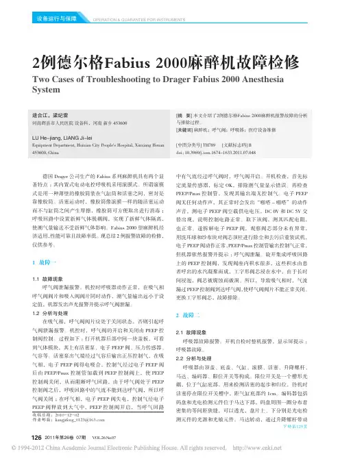
2011年第26卷 07期 V OL.26 No.07126OPERATION & GUARANTEE FOR INSTRUMENTS德国Drager 公司生产的Fabius 系列麻醉机具有两个显著特点:其内置式电动电控呼吸机采用滚膜式。
所谓滚模式是用一种薄壁的橡胶筒装在气缸筒和活塞之间,密封是靠橡胶筒。
活塞运动时,橡胶筒像滚膜一样的随活塞运动而不与缸筒之间产生摩擦,橡胶筒可方便取出进行消毒;呼吸回路中设置新鲜气体脱耦阀,实现了新鲜气体隔离,使潮气量输送不受新鲜气体影响。
Fabius 2000型麻醉机经济适用,性能可靠且故障率低。
现总结2例报警故障的检修,仅供参考。
1 故障一1.1 故障现象呼气阀泄漏报警。
机控时呼吸器动作正常,在吸气相呼气阀阀片和吸入阀阀片同时动作,潮气量输出远小于设定值,机器发出声光报警并提示呼气阀泄漏。
1.2 分析与处理在吸气相,呼气阀阀片应处于关闭状态,否则引起呼气阀泄漏报警。
机控时,呼气阀的开启和关闭由PEEP 控制阀控制。
过程如下:打开机器后部中间一块盖板,可看到气体模块,其上有活塞泵、电子PEEP 阀、压力传感器、气容等。
活塞泵出气端经过气容后输出正压控制气,在吸气相,电子PEEP 阀得电吸合,控制气经过电子PEEP 阀后由PEEP/Pmax 控制管加载到PEEP 控制阀上,使PEEP 控制阀关闭,从而阻断呼气回路,由于呼气阀处于PEEP 控制阀之后,呼吸回路中的气流不能到达呼气阀,所以呼气阀关闭;在呼气相,电子PEEP 阀失电,控制气经电子PEEP 阀释放到大气中,PEEP 控制阀开启,当呼气回路中有气流经过呼气阀时,呼气阀开启。
开机检查,首先标定流量传感器,标定OK,排除潮气量显示错误。
再检查PEEP/Pmax 控制管,发现其输出端无控制气。
电子PEEP 阀无任何动作声,其正常时会发出“啪嗒-啪嗒”的动作声音,测电子PEEP 阀空载供电电压,DC 0V 和DC 5V 交替出现,说明控制电路正常。
麻醉机技术的最新发展压疗役畚僧垂麻醉机技术的最新发展陈华,冯靖{韦(浙江大学医学院附属第一医院,浙江杭州310003)【摘要】麻醉机是进行吸入麻醉的重要工具.本文介绍了麻醉机的基本组成和工作原理,并阐述了在最新麻醉机中呼吸器,蒸发器,气体流量控制等部分的技术发展趋势.【关键词】麻醉工作站;呼吸器;电子蒸发器;电子流量控制阀I中图分类号】TH789【文献标识码】A【文章编号】1007—7510(2005)02—0034—02ThecurrenttechnologyoftheanesthesiamachineCHENHua,FENGJing—yi (TheFirstHospitalAffiliatedtoMedicalCollegeofZhejiangUniversity,HangzhouZhejiang 310003,China)Abstract:Theanesthesiamachin【1isaveryimportantdeviceintheinhalationanesthesia.Thepaperintroducesthebasic configurationandprinciplesoftheanesthesiamachine.Anditdescribescurrenttechnologica ldevelopmentintheanes—thesiaroachiRe.Keywords:AI)U;ventilator;electtonicanestheticvaporizer;electronicflowcontrolvalves 随着临床大型手术的开展,利用麻醉机进行吸人性全身麻醉成为一种广泛使用的麻醉方式.在进行吸人全身麻醉过程中,麻醉师需通过麻醉机向病人连续给氧,给气,给吸人麻醉剂,并用机械通气来替代手术病人的自我呼吸.同时,麻醉师还要利用监护仪器来观察病人的生命体征,及时对病人进行呼吸管理,精确控制吸入气体和吸入麻醉剂的浓度现在,I)atcx—Ohmeda公司和1)rager公司分别将各自的麻醉机和监护仪紧密结合在一起,推出了新一代的麻醉工作站.使临床手术中进行吸人性麻醉更稳定更安全.麻醉机一般由呼吸机,呼吸回路,蒸发罐,气体供给系统,呼吸监测系统和废气排出系统等组成.特别是在麻醉工作站中,还添加了一系列病人生命体征监测系统和麻醉信息分析管理部分.近期,麻醉机中各部件的技术均有很大发展,以下一? 阐述各部件的主要技术发展趋势.l紧凑型呼吸回路和全能型电动电控呼吸器呼吸回路系统是麻醉机与病人相连的气路装置.它负责向病人输送麻醉混合气体,回收病人呼出的气体,并将呼出气体中的C02吸收掉,多余的麻醉气体排放掉.它包括:吸气阀,呼出阀,APL阀,PEEP阀,CO2吸收器和呼吸管路.现代麻醉机的呼吸回路开始趋于紧凑化和集成化,它大大缩减了管路死腔和可拆卸部件,从而降低回路阻力,提高呼吸顺应性,降低气体泄漏的可能.集成化的呼吸回路也易于拆卸,清洁和消毒.特别是Datex—OhmedaS/5ADU采用了自动旁路式CQ吸收器,这样使手术过程中可快速方便更换吸收器,也不会影响呼【收稿日期】2004—06—23吸回路中气体平衡.在麻醉过程中,呼吸器用于辅助和控制病人呼吸它是麻醉机必设的组成部分.在现代麻醉机中都配有机控或手控两种呼吸工作方式.它们一般是通过机控/手控开关米切换.在手控方式中,麻醉机将手控气囊接入呼吸到路,麻醉师通过按压气囊控制病人呼吸.在机控方式中,呼吸器被接入呼吸回路中,按照呼吸模式(如PCV,VCV,SIMV)来代替病人呼吸.呼吸器工作原理简单的说就是让机器代替麻醉师按压气键控制病人呼吸.现有的呼吸器一般可分为:气动气控,气动电控和电动电控三种.在这三种呼吸器中,电动电控呼吸器最精准,最稳定,更节省麻醉成本,也越来越被一些高档麻醉机所采用.1)rager公司从Narkomed6000麻醉机开始使用电动电控呼吸器.特别在FabiUSGS和Primus两款麻醉机中均使用的是E—Vent电动电控活塞式呼吸器.它最大的特点就是无需驱动气体.在没有任何气体的情况下,它能像治疗用呼吸机那样精准地控制病人呼吸.E—Yen,呼吸器在病人吸气相时,将新鲜麻醉气体通过呼吸回路人口的一个三通阀输入手控气囊,直至病人呼气相的开始.在病人呼气相时,三通阀将手控气囊与呼吸回路接通,气囊中存有的新鲜气体进入呼吸回路去填充病人所吸收掉的气体.因此它和其他呼吸器最大的区别在于:无论手控或机控模式下,手控气囊都参与病人呼吸工作.另外,由于E—VentT呼吸器采用电动活塞式气体气囊,因此呼吸器气囊均是在轻微负压的情况下进行填充,这种设计使病人呼气只需少量正压就可进行,大大降低可能造成的病人气压伤.特别是在回路漏气或补给的新鲜气体量不够时,呼吸?34?20卷2期2005.2医疗设备僧垂器会打开负压释放阀,让机器周围的气体吸入呼吸回路,来补充不够的气体量.因此麻醉安全性有了很大的提高.2高精度的电子气体流量显示和控制现有的麻醉机中.均配有新鲜气体流量控制部分它包括气体二次减压,/【,(/N:O气体流量凋节和NO一(]2气体比例控制等部分.它精确地控制新鲜混合气体的补给量和混合气体中各种气体比例,从而保证病人能吸入足够的新鲜气体. 也保证补给气体中氧浓度不低于25%.在早期的或中低档麻醉机中,一般采用的是机械式流量汁和N0一()2联动装置.因为机械结构装置精度不高,误差比较大,长久使用也容易失灵,所以现在一些高档麻醉机已开始使用电子的流量显示和控制装置.特别是I)atex—OhmedaS/5 ADU和DragerPrimus麻醉机中更足采用了高档的比例控制阀和电子气体流量传感器,因此麻醉机不仅能自动监测和控制各种气体的补给量,还能像治疗用呼吸机那样自动控制补给气体浓度比例,并精确地按照各种呼吸模式控制病人进行呼吸.在使用电子的流量显示和控制装置后,麻醉师只要设定各种参数值,无需再手动进行气体调节和控制.这种设计还使气体流量控制部分和麻醉机呼吸器精密地结合在?起,从而提高麻醉机的气体控制精度,减轻麻醉师的'E作量,减少人为因素产生的误差,也减少麻醉气体的浪费,从而使吸入麻醉更安全, 更精确,更轻松.3高精度的电子蒸发罐蒸发罐是麻醉机的重要组成部分.它能将麻醉药液转换成蒸汽并按一定量混入新鲜气体中.蒸发罐的工作原理是在蒸发罐的麻醉药液容器一卜方,通入一定量的混合气体,并将其中部分气体通过控制阀进入蒸发室,带走饱和的麻醉蒸汽.带有麻醉蒸汽的气体再在出口和进入旁路室的其余部分气体汇合,形成含仃一定比例麻醉蒸汽的混合气体.进入呼吸回路.影响蒸发罐输出气体浓度的因素有: 温度,压力,混合气体和药液的接触面积等等.目前Datex—OhmedaS/5AI)U已开始使用一种高精度的Aladin,r电子蒸发罐.它的结构与其他机械式蒸发罐相似. 也由蒸发室和旁路室组成.它最主要的技术特点是在蒸发室的(上接第52页)2,5责任和说明信息收到标本时间,报告时间,结果评论,声明,检验者,复核者,签发者."结果评论"包括实验室检查意见,标本状态町能影响的结果,建议进一步的检查内容等."声明"包括"此报告仅对送检标本负责,结果供医师参考"等内容.履行告知复查义务.3检验报告的形式无论是打印还是网络化的检验报告,形式可以多种多样,不过应该做到简洁,美观,有层次,对报告内容进行认真组合和出口安置了一个电子流量控制阀.这个阀由罐内的一个CPU 控制.CI'U接收到蒸发罐的浓度控制盘的信息,根据在蒸发室内的压力,温度传感器以及在蒸发室和旁路室出口的流量汁所提供的信息,也接收气体监测所提供的信息.综合分析后精确地控制流量阀.以达到预期的吸入麻醉药浓度.电子蒸发罐的使用,让麻醉药浓度控制实现自动化,减少了人为误操作的可能,提高了吸入麻醉的安全性.4与麻醉机紧密结合的监测系统和麻醉信息分析系统麻醉机都带有呼吸气体监测系统,一般具有如呼吸回路中气体流量,气体压力,吸入端氧浓度和呼气末C()2浓度等功能.通常,监测系统只是将测出数值和压力波形显示给麻醉师看,让麻醉师通过相关数值判断对麻醉机进行调整.在I)atex—OhmedaS/5AI)U和I)ragerIrimus等机型中,手术中所需的各种监测系统都被融合进麻醉机中,与麻醉机形成一个强大的麻醉工作站.这些监测系统不但包括有呼吸气体监测,麻醉气体分析,麻醉深度监测等功能,而且还有心电脑电监测,血氧浓度监测,血液动力监测,肌松监测等功能.监测系统不仅自动将所得到的数值提示给麻醉师,也能自动地去调节麻醉机新鲜气体流量,蒸发罐的药物浓度和控制呼吸器的工作状况,帮助麻醉师安全地进行吸入麻醉.同时,麻醉机自动记录机内各个电子传感器所得数值.分析软件在整个麻醉结束后,自动地向麻醉师生成病人麻醉丁作报告.随着麻醉机工业技术的飞速发展,麻醉机越来越电子化,集成化和智能化.各个部件结合紧密,协凋配合工作.特别是麻醉工作站的出现,它友好的用户界面,全面的病人生理参数监测,集成化的呼吸管路,高性能的呼吸器,精确的电控气体输送系统,强大的病人麻醉管理系统,均代表了现代麻醉机技术的发展方向.麻醉工作站使实施理想中的低成本,高效率,高安全性的吸入麻醉成为可能,也使麻醉师的工作变得更轻松. 【参考文献】[1】于昕,韩松.现代麻醉机的基本原理及新发展【J】,中国医疗器械杂志.2003,(1):44—46.☆排列,便于临床医生分析和理解.还要便于病历档案的粘贴和整理.便于成批打印或查询打印等.目前报告单打印的方式有:套打(先印刷检验报告表格,然后根据内容打印填表),针式打印机,喷墨打印机,激光打印机.各有优缺点,建议用激光打印机.速度快,效果好.套打不灵活,打印内容容易错位,也不美观.关于申请单的问题.也有一些规范,主要是便于检验目的选择,包含不同标本的颜色区别,条码标签,申请医师,测定时间等信息.见图I.☆20卷2期2005.2?35?。
德尔格pac6500说明书
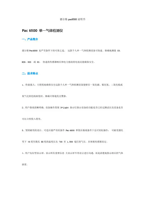
Pac 6500 单一气体检测仪
一、产品简介
德尔格Pac6500 是严苛条件下的可靠之选。
这款个人单一气体检测设备可快速、准确地测量 CO、H2S、SO2 或 O2。
快速的传感器响应和电力强劲的电池还能确保安全。
二、技术特点
1、性能强大,大程度地确保安全这款个人单一气体检测设备能够在一氧化碳、硫化氢、二氧化硫或氧气达到危险浓度时,准确可靠地发出警报。
2、用户指南清晰明确,设备操作简便 D-Light 指示灯指示设备的功能是否已经过测试以及设备是否可以立即投入使用。
3、坚固耐用的设计,可适应最严苛的条件 Pac 6500 即使在极端条件下也可轻松操作:可耐受摄氏零下 40度至摄氏 55度的温度以及 700 至 1,300 毫巴的气压,具体视传感器而定。
4、用户友好型显示屏,显示所有重要信息大显示屏不用语言进行沟通,而是清楚地指示相应的气体浓度。

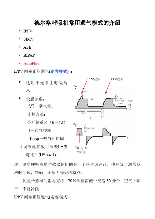
德尔格呼吸机常用通气模式的介绍• IPPV • SIMV • ASB • BIPAP • AutoFlowIPPV 间歇正压通气(定容模式) :注:测量呼吸流量传感器使用的是一个热丝风速计,他具备了测量反应时间短,精确,无压力损失的特点。
流量传感器的消毒方法:70%酒精溶液中浸泡60分钟,空气中晾干,不能冲洗。
IPPV 间歇正压通气(定容模式)• 适用于无自主呼吸病人•设置参数:VT -潮气量。
计算方法:公斤体重×(8-12) f -通气频率 Tinsp -吸气相时间. (调节此参数可改变I:E 吸呼比)(I:E <4:1)PLV 波形I PPV 波形 恒定吸气流速注:空气滤水器垂直的安防在呼吸机的空气输入口,旋松底下的旋钮即可排水。
滤水器中的水位不能超过max 水平线。
呼吸机系统简图:SIMV 同步间歇指令通气 (定容模式)PEEP -呼气末正压。
一般设置小于5mbar 。
主要是改善氧合,防止肺泡塌陷 FlowAcc -吸气流速 FiO2Pmax -最高限压(防止损伤。
PLV 压力限制通气) VT 报警PLV 波形IPPV 波形 恒定气流速无创通气:通过面(鼻)罩和管道的连接有创通气:通过气管插管或气管切开和管道的连接• 适用于有自主呼吸不强的病人 •脱机• 参数: • VT, f ,• FlowAcc ,Tinsp •TriggerTrigger window -触发窗 (成人5秒,小儿1.5秒.) f, VT 不变SIMV/ASB P ASB -压力支持SIMV 波形呼气相病人自主呼吸,触发窗内启动机械通气触发窗外启动压力支持注:呼吸机与病人的的连接方式:注:单词解释Ppeak------------------峰值压力 MV------总分钟通气量 Pplat ----------------平台压 MVleak------分钟漏气量 Pmean----------------平均压 MVspon----自主呼吸分钟通气量 PEEP-----------------呼气末压力 ftot------总呼吸频率Pmin------------------最小气道压力 fspn-----自主呼吸频率spontaneous fmand----设置呼吸频率 VTi-----------吸入潮气量 T------气道温度VTe----------呼出潮气量 R------气道阻力resistance FiO2----------监测氧浓度 C------肺顺应性complianceASB 压力支持窒息通气高Ramp 压力支持 低Ramp 压力支持达到触发灵敏度,机器启动压力支持ASB/PSV 压力支持气道持续正压通气(continue positive airway pressure, CPAP):除了调节CPAP 旋钮外,一定要保证足够的流量,应使流量加大3~4倍。
麻醉科中的新技术及器械介绍随着医学科技的不断发展,麻醉科作为医学领域的重要一环,在新技术和器械的引领下,得以不断提升麻醉效果和患者的手术体验。
本文将对麻醉科中的新技术及器械进行介绍,让我们一同了解这些革新性进展。
一、静脉内麻醉技术静脉内麻醉技术(Intravenous Anesthesia)是一种通过静脉内给药实现全身麻醉的方法。
与传统的气管插管麻醉相比,该技术具有更小的创伤,恢复迅速,避免了气管插管的痛苦和并发症风险。
近年来,随着药物的不断研发和改良,静脉内麻醉技术已经成为麻醉科中的热门技术之一。
1. 智能输液泵智能输液泵作为静脉内麻醉的关键设备之一,具有精确计量、自动报警、远程监控等功能。
其稳定的输液速度可以确保药物的准确给予,并降低了输液过程中的误差。
智能输液泵可以实时监测药物输注速度,一旦发生异常情况,比如药物输注速度过快或过慢,系统会自动发出警报提醒医护人员及时处理,确保患者的安全。
2. 静脉内置管静脉内置管(Intravenous Catheter)是静脉内麻醉的关键器械之一,其通过刺破皮肤及血管,将导管插入静脉内,以便输注麻醉药物。
近年来推出的一种新型静脉内置管,具有更小的刺激性和疼痛感,能够更好地减少皮肤创伤,提升患者的手术体验。
二、无创监测技术无创监测技术是指通过非侵入性手段,对患者的生理指标进行监测的技术。
在麻醉科中,无创监测技术的应用极大地提升了患者的安全性和手术效果。
1. 脉搏氧饱和度监测仪脉搏氧饱和度监测仪(Pulse Oximeter)是一种常用的无创监测设备,通过光电传感技术,可以实时监测患者的血氧饱和度和心率等情况。
该监测仪可以通过一个夹在患者指尖上的传感器,传递红外线和红外线光束,根据光的吸收程度计算出血氧饱和度和心率等生理参数。
脉搏氧饱和度监测仪的引入,让医护人员能够实时监测患者的氧合情况,一旦发生异常,可以及时采取措施,避免发生严重的氧合不足。
2. 非侵入性血压监测仪非侵入性血压监测仪(Non-invasive Blood Pressure Monitor)以无创的方式实时监测患者的血压情况。
【关键字】模式Savina独特的机械通气性能――提供自主呼吸的空间BIPAP(选配件:减少了机械通气的创伤性及镇静剂的使用、改善人机配合有好处脱机,是一种万能的模式。
为ALI/ARDS治疗提供了有效的治疗手段。
Autoflow(选配件):允许急性肺水肿、气胸及支气管哮喘病人在定容通气中自由自在的呼吸。
NIV (选配):可以实现各种模式下的无创通气。
操作方便、便于转运所有的机械通气主要参数唾手可得使用方便;选择-调整-确认理念高度独立性内置电池供应,内置电池供电1小时,而外置电池供电达7小时用户至上机械通气的监测非常全面――波形和测量值其他功能雾化功能、吸氧模式、护士呼叫、综合串行口、nurse call, Ventview市场价格:RMB:26万呼吸机市场上最好的价格性能比卓越的通气性能: 提供给病人自由呼吸的空间BIPAP:减少了机械通气的创伤性及镇静剂的使用、改善人机配合,有好处脱机,是一种万能的模式。
为ALI/ARDS治疗提供了有效的治疗手段。
Autoflow (选配件) :允许急性肺水肿、气胸及支气管哮喘病人在定容通气中自由自在的呼吸。
ATC(选配件):补偿人工气道所造成的额外呼吸功。
NIV(选配件):可以实现各种模式下的无创通气。
用户界面简单而直观的操作理念――选择-调整-确认、帮助功能、引导式检查菜单、辅助信息用户至上个性化的工作平台――用户化;配置――波形、测量值和模式诊断监测附加功能(选配件)――趋势、环、记录本、P0.1、及PEEPi脱机参数(选配件):RSB、NIF、VTASB功能齐全ATC、NIV面罩通气、NeoFlow、CO2监测、SpCO2、联网模块、nurse call、遥控器、后备电源、软件升级市场价格:RMB:32万卓越的通气性能: 提供给病人自由呼吸的空间BIPAP:减少了机械通气的创伤性及镇静剂的使用、改善人机配合,有好处脱机,是一种万能的模式。
为ALI/ARD治疗提供了有效的治疗手段。
手术麻醉系统品牌1. 引言在现代医学领域,手术麻醉是一项非常重要的技术。
麻醉系统是手术过程中必不可少的设备,它能够提供安全、有效的麻醉管理,确保手术顺利进行。
随着科技的进步和医学研究的不断推进,目前市场上有各种不同品牌的麻醉系统供医院和手术室选择。
本文将介绍几个知名的手术麻醉系统品牌,并对其特点和优势进行分析比较。
2. 品牌一:超级麻醉系统超级麻醉系统是一家专注于研发和生产麻醉设备的公司。
他们的麻醉系统采用先进的技术和创新的设计,具有以下特点和优势:•高精度控制:超级麻醉系统使用先进的控制算法,能够精确地控制麻醉药物的输送和浓度,使麻醉管理更加精细。
•智能监测:该系统配备了多个生理参数监测传感器,能够实时监测患者的血压、心率、呼吸等指标,提供准确的监测数据,帮助麻醉医生做出更加科学的决策。
•友好界面:超级麻醉系统的用户界面简洁易用,操作便捷。
医生可以根据患者的具体情况,灵活调整麻醉参数,实现个性化的麻醉管理。
3. 品牌二:安全麻醉系统安全麻醉系统是一家专注于麻醉安全的公司。
他们的麻醉系统具有以下特点和优势:•安全性强:安全麻醉系统采用多重安全防护机制,能够对使用者和患者进行全面的安全保护。
系统会自动检测和报警,避免麻醉过量或麻醉中断等风险。
•数据记录与分析:该系统提供详细的麻醉记录和数据分析功能,可以追踪麻醉过程中的各项指标,并生成报表,方便医生进行后期分析和评估。
•可靠性高:安全麻醉系统采用可靠的硬件和高效的软件算法,确保系统运行稳定可靠,不易出现故障。
4. 品牌三:全能麻醉系统全能麻醉系统是一家提供全方位麻醉解决方案的公司。
他们的麻醉系统具有以下特点和优势:•多功能性:全能麻醉系统集成了多种麻醉设备,包括麻醉机、呼吸机、监护仪等,实现了一体化的麻醉管理。
医生可以在同一个系统上完成所有麻醉操作,提高工作效率。
•定制化服务:全能麻醉系统能够根据医院的实际需求进行定制化配置,满足不同医院和手术室的需求。
德尔格呼吸机的使用及流程引言德尔格呼吸机是一种重要的医疗设备,广泛应用于临床治疗中,特别是对于呼吸功能不全的患者。
本文档将介绍德尔格呼吸机的使用方法和流程,以帮助医护人员正确和有效地操作该设备。
设备准备在使用德尔格呼吸机之前,需要进行一系列的设备准备工作。
1.检查设备完整性和工作状态。
确保德尔格呼吸机无损坏、正常工作。
2.确认呼吸机的电源和各个连接线是否连接稳固。
3.准备好合适的面罩或导管,并确保其清洁卫生。
4.检查呼吸机的气囊是否完好,气囊应具备弹性。
操作步骤以下是使用德尔格呼吸机的具体操作步骤:1.将呼吸机放置在稳固的平面上,并连接电源。
2.按下电源按钮,启动呼吸机。
呼吸机的显示屏将显示相关的参数和配置选项。
3.根据患者的具体情况,选择合适的通气模式和参数设置。
常见的通气模式包括控制通气、辅助通气、压力支持通气等。
4.将面罩或导管与呼吸机连接。
确保连接牢固,无漏气现象。
5.将面罩或导管打开,并安装在患者的口鼻部位。
确保面罩或导管与患者的面部贴合密封。
6.调整呼吸机的气囊,并根据需要进行调节,使气囊充满空气并适应患者的脸形。
7.调节通气参数,如吸气压力、呼气压力等,并设置合适的频率和吸呼比。
8.启动呼吸机,开始为患者提供通气支持。
同时,监测呼吸机的显示屏,确保各项参数正常。
注意事项在使用德尔格呼吸机时,需要注意以下事项:1.确保呼吸机的连接线路稳固。
如果出现松动或断开的情况,及时进行修复或更换。
2.定期检查德尔格呼吸机的各项功能和参数是否正常,如电源、面罩密封等。
3.注意卫生。
呼吸机的面罩、导管等需要定期清洁和消毒,避免交叉感染的发生。
4.在使用呼吸机过程中,随时监测患者的呼吸情况和血氧饱和度。
如出现异常情况,及时采取相应的措施。
5.注意患者的舒适度。
在设置通气参数时,需要根据患者的具体情况进行调整,以保证患者的舒适性和安全性。
结论德尔格呼吸机是一种重要的医疗设备,在临床治疗中发挥着重要作用。