
充电器英文说明书
- 格式:doc
- 大小:182.00 KB
- 文档页数:1
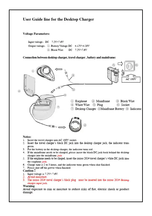

电动车充电前中英文说明书1.充电前仔细阅读说明书.2.户内使用,注意防潮、淋雨.3.充电前确认充电器与电池相符.4.禁止给不能充电的电池充电.5.接通或断开充电器与电池连接前,6请先断开充电器.7.避免将充电器随车携带,造成机械损坏8.内有高压,非专业人员请勿拆开.9.充电时,请勿让小孩子接近。
10.指示灯为红色时正在充电器,11.指示灯为红色时,充电完成.1. Read the instruction carefully before charging.2. Indoor use, pay attention to moisture, rain.3. Confirm charger before charging the battery line.4. It is prohibited to charge not charge battery.5. Before connecting or disconnecting the charger from the battery6.connection,Please disconnect the charger.7. Avoid truck to carry the charger, causing mechanical damage8. High pressure, non-professionals, do not disassemble.9. When charging, do not leave the child close.10. Charger when the light is red,11. When the indicator light is red, charging is complete.。

ControlsTo use the wireless charger, the power mode must be in ACCESSORY or ON.Charge any devices compatible with Qi wireless charging on the area indicated by the mark as follows:1.Place the device you want to charge on the charging area.u The system will automatically startcharging the device, and the greenindicator light will come on.u Make sure that the device is compatible with the system and placed with the chargeable side in the center of the charging area.2.When charging is completed, the green indicator light will go off.u If the device is not located on the charge area correctly, the green indicator light will blink.■Wireless Charger *1Wireless Charger *RF Radiation Exposure Statement:This equipment complies with FCC RF Radiation exposure limits set forth for an uncontrolled environment.This device and its antenna must not be co-located or operating in conjunction with any other antenna or transmitter.In order to use safely:•Remove any metal objects from the charge pad before charging a device.•Do not open the charger case.•Do not use the charger if it malfunctions.Contact your dealer.GreenIndicatorCharging AreaControls ■When charging does not startPerform one of the solutions in the following table.Indicator Cause SolutionSlow BlinkThere is an obstacle(s) betweenthe charging area and thedevice.Remove theobstacle(s).The device is not within thecharging area.Pick up and reset thedevice to the center ofthe charging areawhere is located.The temperature of the wirelesscharger pad increases.Temporary suspendcharging the device.Wait for temperatureto drop and attempt tocharge the deviceagain.Fast Blink The wireless charger is faulty.Turn the vehicle offand back on. If theindicator still blinks,contact a dealer.1Wireless Charger*Using the audio/information screen, you can disablethe wireless charger function.2Customized Features P.2993CAUTIONMetal objects between the charge pad andthe device to be charged will get hot andcan burn you.•Always remove foreign objects from thecharge pad before charging the device.•Be sure the surface is clear of dust andother debris before charging.•Do not spill liquids (i. e. water, drinks,etc.) on the charger and the device.•Do not use oil, grease, alcohol, benzineor thinner for cleaning the charge pad.•Do not cover the system with towels,clothing, or other objects while chargingetc.•Avoid spraying aerosols which may comein contact with the charge pad surface.Controls1Wireless Charger *This system consumes a lot of power. Do not use the system for a long time when the engine is not running. This may weaken the battery, making it difficult to start the engine.When using the wireless charger, check the user’s manual that came with the compatible device you want to charge.The wireless charger can support up to 5 W, but the charging rate varies based on the device and other conditions.NOTICEDo not place any magnetic recording media or precision machines within the charging area while charging.The data on your cards such as credit cards can be lost because of the magnetic effect. Also precision machines such as watches can be affected.“Qi” and marks are the registered trademarks owned by Wireless Power Consortium (WPC).In the following cases, charging may stop or not start:•The device is already fully charged.•The temperature of the device is extremely high while charging.•You are at a place that emits strongelectromagnetic waves or noises, such as a TV station, electric power plant, or gas station.•The device has a cover, case or accessories which are not compatible with wireless charging.Controls 1Wireless Charger*A device may not charge if the size or shape of its chargeable side is not appropriate for use with the charging area.Not all devices are compatible with the system. During the charging phase, it is normal for the charging area and device to heat up.Charging may be briefly interrupted when:•All the doors are closed-to avoid interference with the proper functioning of the keyless access system.•The position of the device is altered.Do not charge more than one device at a time on a charging area.If the device becomes too hot and its battery protection function activates, it may charge extremely slowly or no longer charge.The temperature at which the battery protection function activates depends on the device.。

User Manual ofUniversal Smart Charger (18A, 29.6V-58.4V Cut-Off) for 36V-48V SLA , 29.6V-51.8V Li-Ion/LiMnNi (8-14 Cells),38.4V-51.2V LFP(12-16 Cells) -- CE listedAA Portable Power Corp ()Address: 860 S, 19th St, Unit A, Richmond, CA, 94804Tel: 510-525-2328Fax: 510-439-2808Email:**********************Prepared & Approved by Max (09/29/10)Warning•Must select AC input voltage correctly before plug to Wall AC outlet•Must connect to battery with correct polarity•Must use with battery pack capacity >= 18Ah•Must use with SLA (36V-48V, 18-24Cells), Li-Ion/LiMnNi (29.6V-51.8V, 8-14Cells), LifePO4 (38.4V-51.2V, 12-16Cells) Battery•Must select charging voltage correctly based on battery type/battery voltage used•We are not responsible for any damage caused by misuse.•Professional & Indoor use only•Don't remove the case to prevent from electric shock •Unplug the charge from AC outlet after use.Features:•High Quality Intelligent smart charger (Manufacture part#KP4818CL) designed for SLA (36V-48V, 18-24Cells), Li-Ion/LiMnNi (29.6V-51.8V, 8-14Cells), LifePO4 (38.4V-51.2V, 12-16Cells) Battery pack•Adjustable Charging voltage from 29.6-58.4VDC•Must select charging voltage correctly based on battery used below o Li-Ion / LiMnNi = 4.17V / cellEx. Charging voltage for 51.8V (14Cells) Li-Ion/LiMnNi =4.17V x 14 = 58.38Vo LiFePO4 = 3.55V / cellEx. Charging voltage for 51.2V (16Cells) LiFePO4 =3.55V x 16 = 56.8Vo SLA = 2.43V / cellEx. Charging voltage for 48V (24Cells) SLA = 2.43 x 24 =58.32V•Charging Stage: CC (Constant Current) --> CV (Constant Voltage) --> Floating •Switch-Mode Technologyo Convert from AC input voltage to DC charging voltage 1677 times faster than traditional linear chargero Unit will be smaller, lighter and higher efficiency than traditional linear charger•Built in cooling fan to ensure charger long service life•Input AC power: World-Wide 90-132VAC / 200-240VAC , 47-63Hz, USA AC plug o For international use, please click here to order AC plug adaptor seperately•Cut-Off Automatically when the battery is fully charge•Safety protectiono Over Current & Over Voltage protectiono Short Circuit protectiono Reverse polarity protection•Charging Voltage: 29.6-58.4VDC•Charging Current: 18.0A +/- 0.5A•Max Power output: 1200W•Charging time:o Li-Ion / LiMnNi Charging time = (1.5 x Ah rate of the pack) / charge current.o LiFePO4 Charging time = (1.41 x Ah rate of the pack) / charge current.o SLA Charging time = (1.2 x Ah rate of the pack) / charge current. •Battery pack Capacity:>= 18Ah•Stylish Aluminium Enclosure•Built in 2 unit of LED indicatoro Power ON: LED 1 = Redo Charging (Constant Current): LED 2 = Redo Charging (Constant Voltage): LED 2 = Redo Fully charger: LED 2 = Green•Charging terminal : 4' long 8AWG wire 1.9" x 1.5" x 0.6" Standard Anderson connector•Dimension (LxWxH): 260mm(10.2") x 175mm(6.9") x 90(3.5")•Weight: 9.9 lbs (4.5kg)•High Efficiency: 85-95%•MTBF (Mean Time between Failure): 30,000 POH (Power on Hour) = 10 years of everyday operation of 8 hours•CE listed•Operating Temperature: 14F(-10’C) ~ 113F(45’C)Charging cycle:If the LED1 is ON ( Red ), it shows that input power is ON.The explanation of the charging cycle is as following.Stages Condition Mode Current Voltage LEDIndicationStage 1 Constant Currentmode CC mode 18A+/-0.5A To 29.6-58.4V(Based onvoltageselection)RedStage 2 Constant Voltagemode CV mode Reduces from18A+/-0.5AHolds at 29.6-58.4V(Based onvoltageselection)Red* CC mode = Constant current charge*CV mode = Constant voltage charge*** See Stage 2 description belowStage 1: Constant Current Mode (CC):The charger changes to constant current 18A+/-0.5A. When thebattery voltage reaches up to 29.6-58.4V (Based on voltage selection), the charging stage changes from CC (Constant Current) to CV(Constant Voltage) mode.Stage 2: Constant Voltage Mode (CV):In this stage the voltage of each cell in the battery is equalized. The charger holds the battery at 29.6-58.4V (Based on voltage selection) and the current slowly reduces.Charging Curve:Detail PictureFront ViewNote-MUST Set Charging Voltage CORRECTLY Beforeconnect to battery.-Don’t reset charging voltage while charging.-Wrong charging voltage setting may explode battery.BatterySpace don’t responsible for any damage fromany miss-use-57.9VDC Maximum charging voltage can be set after power turn “On”. To set charging voltage up to58.4VDC, please connect battery to charger first ,then warm up charger about 30 minutes-Charging Current can not be set-Charging current can be viewed via Charging current Display switch PositionBack ViewNote- MUST Select AC INPUT Voltage Correctly Before plug to Wall AC outletNote- For USA customer, MUST SELECT to “115VAC Input Switch Position”Connector DetailCharging Terminal: 1.9" x 1.5" x 0.6" Standard Anderson connectorIncluded 1 pcs 1.9" x 1.5" x 0.6" Polarity assignment & wire soldering locationStandard Anderson connector for DIY use for Included Standard AndersonNote:-Wrong polarity will damage the charger, and Batteryspaceare not responsible for the damage or losses caused bymisusing。

RD-E SERIES | INVERTER/CHARGERFeatures• Easy-to-install – Install the RD-E Series in four easy steps. See your installation manual for specific instructions.• Versatile mounting – Mount the RD-E Series on a shelf or wall.• Multiple ports – The RD-E Series provides multiple ports,including an RS485 communication port for network expansion, and a remote port.• Accessible design – The extra large AC access cover with terminal screw block and 360° DC connection terminals with covers make this inverter easily accessible.• Buy with ease – The RD-E Series is backed by a two-year (24-month) limited warranty.IntroductionSensata Technologies now offers the RD-E Series Inverter/Charger for 230 VAC / 50 Hz installations. The RD-E Series comes with all of the features you’ve come to expect from a Magnum brand product, including: Power Factor Corrected (PFC) Charger: Our PFC charger is built into all of our inverter chargers. It uses less energy from a generator than a standard charger – using 25-30% less AC current than standard chargers. Battery temp sensor: The standard battery temp sensor monitors temperatures from 0 - 50° C. Convenient switches: All RD-E Series models comewith an on/off inverter-mounted switch with an easy-to-read LED indicator.Model Numbers• RD2624E • RD4024EAvailable For• Renewable Energy Systems Off-grid Power Back-up PowerAvailable Accessories• AGS• Battery Monitor Kit • Conduit Box• DC Load Disconnect • Fuse Blocks• Ignition Switch Lockout • Remote - ME-RC • Remote - ME-ARC• Remote Switch Adapter242600-4000 VABattery Voltage OptionsContinuous Output OptionsModified Sine WaveSPECIFICATIONSPage 3CONTACT USAmericasEverett, WA 425-353-8833***********************InternationalMagnumInternationalSales@Power ConversionSensata Technologies, Inc. (“Sensata”) data sheets are solely intended to assist designers (“Buyers”) who are developing systems that incorporate Sensata products (also referred to herein as “components”). Buyer understands and agrees that Buyer remains responsible for using its independent analysis, evaluation and judgment in designing Buyer’s systems and products. Sensata data sheets have been created using standard laboratory conditions and engineering practices. Sensata has not conducted any testing other than that specifically described in the published documentation for a particular data sheet. Sensata may make corrections, enhancements, improvements and other changes to its data sheets or components without notice.Buyers are authorized to use Sensata data sheets with the Sensata component(s) identified in each particular data sheet. HOWEVER, NO OTHER LICENSE, EXPRESS OR IMPLIED, BY ESTOPPEL OR OTHERWISE TO ANY OTHER SENSATA INTELLECTUAL PROPERTY RIGHT, AND NO LICENSE TO ANY THIRD PARTY TECHNOLOGY OR INTELLECTUAL PROPERTY RIGHT, IS GRANTED HEREIN. SENSATA DATA SHEETS ARE PROVIDED “AS IS”. SENSATA MAKES NO WARRANTIES OR REPRESENTATIONS WITH REGARD TO THE DATA SHEETS OR USE OF THE DATA SHEETS, EXPRESS, IMPLIED OR STATUTORY, INCLUDING ACCURACY OR COMPLETENESS. SENSATA DISCLAIMS ANY WARRANTY OF TITLE AND ANY IMPLIED WARRANTIES OF MERCHANTABILITY, FITNESS FOR A PARTICULAR PURPOSE, QUIET ENJOYMENT, QUIET POSSESSION, AND NON-INFRINGEMENT OF ANY THIRD PARTY INTELLECTUAL PROPERTY RIGHTS WITH REGARD TO SENSATA DATA SHEETS OR USE THEREOF.All products are sold subject to Sensata’s terms and conditions of sale supplied at SENSATA ASSUMES NO LIABILITY FOR APPLICATIONS ASSISTANCE OR THE DESIGN OF BUYERS’ PRODUCTS. BUYER ACKNOWLEDGES AND AGREES THAT IT IS SOLELY RESPONSIBLE FOR COMPLIANCE WITH ALL LEGAL, REGULATORY AND SAFETY-RELATED REQUIREMENTS CONCERNING ITS PRODUCTS,Testing for specifications at 25° C.Specifications subject to change without notice.GENERAL NOTES。