汽车专业毕业设计 翻译 中英文(全)lean remanufacture of an automobile clutch
- 格式:doc
- 大小:554.00 KB
- 文档页数:38

草图,概念发展和汽车设计草图设计和它的在概念设计中关键作用已经被确认,将这种特殊的汽车设计进行了定义:一份简短的关于总体的概念草图和视觉思维方法的作品。
这个特殊的汽车设计草图的特点是:从线、皇冠线、区域线、阴影和着色进行了描述,进行了分析。
这显示了轮廓线在汽车设计草图的重要位置。
通过观察毕业生和六位专业设计师设计过程,确认了轮廓线在设计过程的重要性和在相互反复的概念设计过程中草图设计的中心地位,这表明计算机辅助设计系统(CAD)系统的设计必须考虑草图设计的重要性。
关键词:概念设计,制图,形象思维,汽车设计,计算机辅助设计大部分的设计理论和制图研究工作一直是基于建筑和工程领域除了托维,都不能将汽车设计师的想法直接显示出来。
因为这种方式的特殊性和因为高水平的设计和工业发展,对比“计算机辅助设计”在其他领域的应用,这种计算机辅助设计已经成为工业中的特定词。
计算机辅助造型工作都集中在三维视图替代草图,例如“虚拟粘土造型”或简单的传统的CAD表面造型。
在汽车设计师和其他领域设计师之间有很多表面的相似。
一个关键问题是其他领域的设计研究转变成特殊学科的范围和一般性结论应用的态度。
我们的研究已经在工业设计中的概念草图设计,我们已经完成了大量的正式案例来观察设计师和了解其技术和草图内容。
结果表面他们的想法在传统的纸和笔上能快速的反应看来,尽管计算机辅助很有效,但并未被设计师与传统方式一样接受。
这些观测结果显示,生产设计思想似乎依靠互动的概念草图(我们可以看到后者,从而证实了先前的研究人员的观察结果)。
草图通过最初的表现产生的轮廓线,其次是使用阴影修改二维造型。
这个研究的意图的研究旨在探讨这些线是否能形成基础CAD工具生产的3D几何形状的草图,观察阴影是否可以改善几何表妹修饰。
此外,关注的焦点是在早期,在世界汽车工业中的概念的显著发展阶段,目的是早期的应用三维几何学促进概念学的发展和加速他们的交流和其他部分的评价。
The Automobile in the United StatesHistory 389, section 3. George Mason University. Spring 2010Science and Technology I, room 224. Tuesdays and Thursdays, 12 – 1:15 pm.Course Blackboard site: General advice: /teachingProfessor Zachary M. SchragE-mail: zschrag@ (please include ―389‖ in subject header).Office: Robinson B 357A. Tel. 703/594-1844. Office Hours: Mondays, 2-4 pm.While I greatly enjoy meeting students individually, department meetings and other commitments occasionally force me to cancel scheduled office hours, so please let me know in advance if you are coming to office hours. If you would like to meet some other time, please send me an e-mail with two or three proposed times.Course DescriptionThis course examines the biography of one of the most important characters in twentieth-century U.S. history: the automobile. Embracing the histories of business, policy, labor, the environment, technology, and culture, this course seeks a holistic understanding of the role of the car in American life. It will examine the invention and adoption of the automobile, the rise of assembly-line manufacturing, the evolution of roadside architecture, and the challenges posed by oil shortages. It seeks to draw a variety of students and encourage them to think about one of the fundamental interactions between humans and machines in the history of the nation and in their own lives.GoalsIn this course, students will:∙Reflect on the significance of the automobile in shaping the America we know today, including their own daily lives.∙Use the automobile to understand the interconnections among technology, business, labor, culture, and politics.∙Practice critical reading of primary and secondary sources, including texts, images, music, and motion pictures.∙Practice research skills using sources in electronic databases, on paper, and in the world around us.∙Practice skills of writing, editing, and revision.Readings∙Kathleen Franz. Tinkering: Consumers Reinvent The Early Automobile.University of Pennsylvania Press, 2005. ISBN-10: 0812238818∙Stephen Meyer. The Five Dollar Day: Labor Management and Social Control in the Ford Motor Company, 1908-1921. State University of New York Press, 1981. ISBN-10: 0873955099∙Chester Liebs. Main Street to Miracle Mile: American Roadside Architecture. The Johns Hopkins University Press; Reprint edition, 1995. ISBN-10: 0801850959∙Tom McCarthy. Auto Mania: Cars, Consumers, and the Environment. Yale University Press (2009), Paperback. ISBN-10: 0300158483. ISBN-13: 9780300158489∙Gordon Harvey. Writing With Sources: A Guide for Students. Second edition. Hackett, 2008. ISBN13: 9780872209442∙Zachary M. Schrag, ―Guidelines for History Students,‖/teaching/teaching.html.CollaborationThis course is designed to encourage the kind of collaboration that makes scholarship so much fun. While you are responsible for your own essays, you will get a great deal of help from each other identifying and interpreting primary and secondary sources, and revising your work.You must credit your classmates for the help that they give you, since a scholar should be proud of the use she has made of others’ work. Citation need not be terribly formal, but I suggest the following forms for citing work by your classmates:∙Joanna Student, "Lincoln’s Imagery," 26 January 2010, History 389 Discussion Board.For a document posted by a student, but written by someone else:∙Lisa Rein, ―Daring to Dream of Reducing Tysons Traffic,‖ Washington Post, 10 December 2009 (posted by Joanna Student).Online ComponentsExcept for the peer-editing, this course is designed to be paperless; all assignments except for the essay drafts should be posted on Blackboard, . You will also receive essay comments electronically.AssignmentsPlease note than 105 percentage points are available, to allow for illness, family emergencies, and other mishaps.Attendance and Participation (15 percent)Much of this course is discussion based, which means that each student’s learning de pends on the other students’ being prepared, punctual, and active. The participation grade is designed to encourage you to help other students learn, and to prepare you for a lifetime of meetings.The participation grade is based on your prompt arrival and active participation in discussions. The highest participation grades will go to students who animate class discussions by asking questions of their peers. The most valuable contributions often begin with the words, ―I don’t understand.‖ Answering such qu estions, and questions posed by the instructor, is also helpful.You should be in your seat, ready to take notes at 12 noon; chronic tardiness will lower your grade. To be counted as on time, you must sign in by 12 noon. To be counted present, you must sign the late attendance sheet. If you need to leave early, please speak to me before class. If you leave early without notifying me, you will be counted absent.You are expected to attend class twice a week. To allow for family and medical emergencies, up to two weeks’ absence is excused. After that, absence for any reason will sharply lower your grade, until you have missed half the course. At that point, you will receive no credit for participation. Chronic absence or tardiness will also affect the grades on your written work.At the end of each unit, you will submit a participation memo, explaining your contribution to the class discussions and your plans for future discussions.Reading Responses (8 percent. 1 percent each)On twelve occasions during the course, you are assigned short responses. They are due at 9 am on the day indicated.On discussion days for which you submit a response, you should be prepared to be called on to describe your findings to the class.There are two kinds of responses:Reading responses (1 point each)On eight occasions, you are assigned responses to the readings. Questions will be posted on Blackboard:.1. Choose one of the questions for that day’s reading and write a one-paragraph response, roughly 125 – 175 words. Write your response as if it were part of a longer essay. Begin with a clear topic sentence (See /teaching/topicsentences.html) that makes an argument rather than just stating facts. Then support that argument with specific facts and quotations from the reading. Use parentheses to indicate page numbers. I suggest you compose your response in a word processor or text editor, then paste it into the discussion board. Research responses (9 percent. 3 points each)On three occasions, you are asked to complete small research assignments. You will be assigned to a group, which will determine specific deadlines. Points are based on the ability of your choice of documents and analysis to spark class discussion.Specific assignments will be posted on Blackboard. All research assignments require the following steps:1. Find a document or image according to the specific assignment instructions.2. Write a one-paragraph analysis of the document or image following the examples at ―Document Analysis‖ </teaching/documentanalysis.html> or ―Image Analysis‖3. Post the document on the appropriate Blackboard discussion, along with the document as an attachment.Essays (60 percent. 15 percent each)On four occasions, you are assigned six-ten paragraph essays (roughly 800-1200 words). Please keep in mind the instructions at /teaching/index.html, especially those on thesis statements and topic sentences.The essays require the following steps:1. Read the essay question, posted on Blackboard.2. Assemble evidence from the assigned readings, from the documents you and your classmates have gathered, and from music and films played in class. Each essay should contain a mix of evidence from primary and secondary sources from the appropriate unit. Evidence from other units of the course may be helpful as well.3. Develop a thesis statement that answers the question and can be supported by your evidence. See /teaching/thesistemplate.html for a suggested form.4. Write a rough draft of your essay. Bring two copies to class.5. Share your rough draft with two of your classmates during the peer editing session. If you do not receive helpful comments, demand them.6. Revise the draft according to the helpful comments you received.Peer Editing InstructionsYour job as a peer editor is not to correct spelling and minor errors, or to provide uncritical encouragement. Rather, it is to demand that your peers teach you something you did not know before.Your comments should begin with one of the following forms, or a close approximation:1. Your paper corrected a misconception I had. Before reading it, I thought _________. But you showed me . . .2. Your paper answered a question I had. Before reading it, I could not understand why_________. But you showed me . . .3. Your paper explained the significance of _________. Before reading it, I couldn’t understand why _________ was important. But you showed me . . .4. For the most part, this paper did not teach me anything that wasn’t pretty obvious from listening to the lecture and reading the book. But I was struck by your comment that ―_________.‖ This comment [insert phrase 1, 2, or 3]. Could you expand this point into a thesis for the whole essay?Final Exam (10 percent)The final exam will be an in-class essay exam that will ask you to reflect on the course as a whole and to analyze primary documents.Extra Credit (1 percent each; up to 3 percent)The goal of this assignment is to get you to think about the course in relation to your daily life. For each week of the course, you may write a two-paragraph journal entry. Up to three entries will count toward course credit, but you may only submit one per week. The first paragraph should describe something that happened to you or that you witnessed involving ground transportation. It can be something that just happened, a news story or article you saw, or a story from your past—but make it something you’re willing to share with the class. The second paragraph should explain how that event or item illustrates or complicates the themes of the course.ScheduleWeek 1January 19 Introduction—Cars and ChoicesUnit 1: What is a car? 1878-1940January 21 Lecture: The Invention of the Car.Week 2January 26 Discussion. Reading 1 due: Tinkering, 1-73January 28 Workshop: reading primary sources.Read: ―How to Read a Primary Source,‖ ―Document Analysis,‖ and ―ImageAnalysis.‖ /teaching/Week 3February 2 Discussion. Group 1.Research 1 due:early automobiles (Harper’s) February 4 Discussion: Reading 2 due: Tinkering,74-102; 130-166Week 4February 9 Discussion. Group 2.Research 2 due:early automobiles (NYPL brochures) February 11 Peer Editing. Essay 1 draft dueUnit 2: Are cars democratic? 1908-1945Week 5February 16 Lecture: Making the Model T.Essay 1 final due.February 18 Discussion: Reading 3 due: Five Dollar Day, 1-65.Week 6February 23 Discussion: Industry filmsFebruary 25 Discussion Group 3.Research 3 due:(ProQuest historical newspapers). Week 7March 2 Discussion: Reading 4 due: Five Dollar Day, 67-147.March 4 Peer Editing. Essay 2 draft dueSPRING BREAKUnit 3: How should we build for cars? 1945-1973Week 8March 16 Lecture: The Automotive Landscape. Essay 2 final dueMarch 18 Discussion: Reading 5 due: Main Street to Miracle Mile, vi-73Week 9March 23 Discussion: Group 1.Research 4 due Postcards/photosMarch 25 Discussion: Group 2.Research 5 due Postcards/photosWeek 10March 30 Discussion: Group 3.Research 6 due:Photographs/photosApril 1 Peer Editing. Essay 3 draft due.Unit 4: Are cars sustainable? 1955-2010Week 11April 6 Film: Who Killed the Electric Car? Essay 3 final dueApril 8 Discussion: Reading 6 due: Auto Mania, 99-147Week 12April 13 Discussion: Groups 1 and 3.Research 7 due:Car AdsApril 15 Discussion: Reading 7 due: Auto Mania, 148-92Week 13April 20 Discussion: Reading 8 due Auto Mania, 193-252April 22 Discussion: Group 2.Research 8 due Government documents Week 14April 27 Peer Editing. Essay 4 draft dueConclusionApril 29 Exam Review. Essay 4 final due.Final Exam: Tuesday, May 11, 10:30 am – 1:15 pm.在美国汽车历史389,第3节。
Ignition SystemThe purpose of the ignition system is to create a spark that will ignite the fuel-air mixture in the cylinder of an engine. It must do this at exactly the right instant and do it at the rate of up to several thousand times per minute for each cylinder in the engine. If the timing of that spark is off by a small fraction of a second, the engine will run poorly or not run at all.The ignition system sends an extremely high voltage to the spark plug in each cylinder when the piston is at the top of its compression stroke. The tip of each spark plug contains a gap that the voltage must jump across in order to reach ground. That is where the spark occurs.The voltage that is available to the spark plug is somewhere between 20,000 volts and 50,000 volts or better. The job of the ignition system is to produce that high voltage from a 12 volt source and get it to each cylinder in a specific order, at exactly the right time.The ignition system has two tasks to perform. First, it must create a voltage high enough (20,000+) to across the gap of a spark plug, thus creating a spark strong enough to ignite the air/fuel mixture for combustion. Second, it must control the timing of that the spark so it occurs at the exact right time and send it to the correct cylinder.The ignition system is divided into two sections, the primary circuit and the secondary circuit. The low voltage primary circuit operates at battery voltage (12 to 14.5 volts) and is responsible for generating the signal to fire the spark plug at the exact right time and sending that signal to the ignition coil. The ignition coil is the component that converts the 12 volt signal into the high 20,000+ volt charge. Once the voltage is stepped up, it goes to the secondary circuit which then directs the charge to the correct spark plug at the right time.The BasicsBefore we begin this discussion, let’’s talk a bit about electricity in general. I know that this is Before we begin this discussion, letbasic stuff, but there was a time that you didn’’t know about this and there are people who need basic stuff, but there was a time that you didnto know the basics so that they could make sense of what follows.All automobiles work on DC (Direct Current). This means that current move in one direction, form the positive battery terminal to the negative battery terminal. In the case of the automobile, the negative battery terminal is connected by a heavy cable directly to the body and the engine block of the vehicle. The body and any metal component in contact with it is called the ground. This means that a circuit that needs to send current back to the negative side of the battery can be connected to any part of the vehicle’’s metal body or the metal engine block.be connected to any part of the vehicleA good example to see how this works is the headlight circuit. The headlight circuit consists of a wire that goes from the positive battery terminal to the headlight switch. Another wire goes from the headlight switch to one of two terminals on the headlight bulb. Finally, a third wire goes from a second terminal on the bulb to the metal body of car. When you switch the headlight on, you are connecting the wire from the battery with the wire to the headlamps allowing battery current to go directly to the headlamp bulbs. Electricity passes through the filaments inside the bulb, then out the other wire to the metal body. From there, the current goes back to the negative terminal of the battery completing the circuit. Once the current is flowing through this circuit, the filament inside the headlamp gets hot and glows brightly. Let there be light.Now, back to the ignition system, the basic principle of the electrical spark ignition system has not changed for over 75 years. What has changed is the method by which the spark is created and how it is distribute.Currently, there are three distinct types of ignition system. The mechanical ignition systemwas used prior to 1975. It was mechanical and electrical and used no electronics. By understanding these early system, it will be easier to understand the new electronic andcomputer controlled ignition system, so don’’t skip over it. The electronic ignition system started computer controlled ignition system, so donfinding its way to production vehicles during the early 70s and became popular when better control and improved reliability became important with the advent of emission controls. Finally, the distributor less ignition system became available in the mid 80s. This system was always computer controlled and contained no moving parts, so reliability was greatly improved. Most of these systems required no maintenance except replacing the spark plugs at intervals from 60,000 to over 100,000 miles.Let’’s take a detailed look at each system and see how they work.LetThe Mechanical Ignition SystemThe distributor is the nerve center of the mechanical ignition system and has two tasks to perform. First, it is responsible for triggering coil to generate a spark at the precise instant that it is required (which varies depending how fast the engine is turning and how much load it is under). Second, the distributor is responsible for directing that spark to the proper cylinder (which is why it is called a distributor).The circuit that powers the ignition system is simple and straight forward. When you insert the key in the ignition switch and turn the key to the Run position, you are sending current from the battery through a wire directly to the positive (+) side of the ignition coil. Inside the coil is a series of copper windings that loop around the coil over a hundred times before exiting out the negative (-) side of the coil. From there, a wire takes this current over to the distributor and is connected to a special on/off switch, called the points. When the points are closed, this current goes directly to ground. When current flows from the ignition switch, through the windings in the coil, then to ground, it builds a strong magnetic field inside the coil.The points are made up of a fixed contact point that is fastened to a plate inside the distributor, and a movable contact point mounted on the end of a spring loaded arm. The movable point rides on a 4, 6, or 8 lobe cam (depending on the number of cylinder in the engine) that is mounted on a rotating shaft inside the distributor. This distributor cam rotates in time with the engine, making one complete revolution for every two revolutions of the engine. As it rotates, the cam pushes the points open and closed. Every time the points open, the flow of current is interrupted through the coil, thereby collapsing the magnetic field and releasing a high voltage surge through the secondary coil windings. This voltage surge goes out the top of the coil and through the high-tension coil wire.Now, we have the voltage necessary to fire the spark plug, but we still have to get it to the correct cylinder. The coil wire goes from the coil directly to the distributor cap. Under the cap is a rotor that is mounted on top of the rotating shaft. The rotor has a metal strip on the top that is in constant contact with the center terminal of the distributor cap. It receives the high voltage surge from the coil wire and sends it to the other end of the rotor which rotates past each spark plug terminal inside the cap. As the rotor turns on the shaft, it sends the voltage to the correct spark plug wire, which in turn sends it to the spark plug. The voltage enters the spark plug at the terminal at the top and travels down the core until it reaches the tip. It then jumps across the tip of the spark plug, creating a spark suitable to ignite the fuel-air mixture inside that cylinder. The description I just provided is the simplified version, but should be helpful to visualize the process, but we left out a few things that make up this type of ignition system. For instance, we didn’’t talk about the condenser that is connected to the point, nor did we talk about the system didnto advance the timing. Let’’s take a look at each section and explore it in more detail.to advance the timing. LetThe Ignition SwitchThere are two separate circuits that go from the ignition switch to the coil. One circuit runs through a resistor in order to step down the voltage about 15% in order to protect the points from premature wear. The other circuit sends full battery voltage to the coil. The only time this circuit is used is during cranking. Since the starter draws a considerable amount of current to crank the engine, additional voltage is needed to power the coil. So when the key is turned to the spring-loaded start position, full battery voltage is used. As soon as the engine is running, the driver releases the key to the run position which directs current through the primary resistor to the coil.On some vehicles, the primary resistor is mounted on the firewall and is easy to replace if it fails. On other vehicles, most notably vehicles manufactured by GM, the primary resister is a special resister wire and is bundled in the wiring harness with other wires, making it more difficult to replace, but also more durable.The DistributorWhen you remove the distributor cap from the top of the distributor, you will see the points and condenser. The condenser is a simple capacitor that can store a small amount of current. When the points begin to open the current, flowing through the points looks for an alternative path to ground. If the condenser were not there, it would try to jump across the gap of the point as they begin to open. If this were allowed to happen, the points would quickly burn up and you would hear heavy static on the car radio. To prevent this, the condenser acts like a path to ground. It really is not, but by the time the condenser is saturated, the points are too far apart for the small amount of voltage to jump across the wide point gap. Since the arcing across the opening points is eliminated, the points last longer and there is no static on the radio from point arcing.The points require periodic adjustments in order to keep the engine running at peek efficiency. This is because there is a rubbing block on the points that is in contact with the cam and this rubbing block wears out over time changing he point gap. There are two ways that the points can be measured to see if they need an adjustment. One way is by measuring the gap between the open points when the rubbing block is on the high point of the cam. The other way is by measuring the dwell electrically. The dwell is the amount, in degrees of cam rotation that the points stay closed.On some vehicles, points are adjusted with the engine off and the distributor cap removed. A mechanic will loosen the fixed point and move it slightly, then retighten it in the correct position using a feeler gauge to measure the gap. On other vehicles, most notably GM cars, there is a window in the distributor where a mechanic can insert a tool and adjust the points using a dwell meter while the engine is running. Measuring dwell is much more accurate than setting the points with a feeler gauge.Points have a life expectancy of about 10,000 miles at which time have to be replaced. This is done during a routine major tune up, points, condenser, and the spark plugs are replaced, the timing is set and the carburetor is adjusted. In some cases, to keep the engine running efficiently, a minor tune up would be performed at 5,000 mile increments to adjust the point and reset the timing.Ignition CoilThe ignition coil is nothing more that an electrical transformer. It contains both primary and secondary winding circuit. The coil primary winding contains 100 to 150 turns of heavy copper wire. This wire must be insulated so that the voltage does not jump from loop to loop, shortingit out. If this happened, it could not create the primary magnetic field that is required. The primary circuit wire goes into the coil through the positive terminal, loops around the primary windings, then exits through the negative terminal.The coil secondary winding circuit contains 15,000 to 30,000 turns of fine copper wire, which also must be insulated from each other. The secondary windings sit inside the loops of the primary windings. To further increase the coils magnetic field the windings are wrapped around a soft iron core. To withstand the heat of the current flow, the coil is filled with oil which helps keep it cool.The ignition coil is the heart of the ignition system. As current flows through the coil a strong magnetic field is build up. When the current is shut off, the collapse of this magnetic field to the secondary windings induces a high voltage which is released through the large center terminal. This voltage is then directed to the spark plugs through the distributor.Ignition Timing The timing is set by loosening a hold-down screw and rotating the body of the distributor. Since the spark is triggered at the exact instant that the points begin to open, rotating the distributor body (which the point are mounted on) will change the relationship between the position and the position of the distributor cam, which is on the shaft that is geared to the engine rotation.While setting the initial or base timing is important, for an engine to run properly, the timing needs to change depending on the speed of the engine and the load that it is under. If we can move the plate that the points are mounted on, or we could change the position of the distributor cam in relation to the gear that drives it, we can alter the timing dynamically to suit the needs of the engine.Ignition Wires These cables are designed to handle 20,000 to more than 50,000 volts, enough voltage to toss you across the room if you were to be exposed to it. The job of the spark plug wires is to get that enormous power to the spark plug without leaking out. Spark plug wires have to endure the heat of a running engine as well as the extreme changes in the weather. In order to do their job, spark plug wires are fairly thick, with most of that thickness devoted to insulation with a very thin conductor running down the center. Eventually, the insulation will succumb to the elements and the heat of the engine and begins to harden, crack, dry out, or otherwise break down. When that happens, they will not be able to deliver the necessary voltage to the spark plug and a misfire will occur. That is what is meant by “Not running on all cylinders cylinders””. To correct this problem, the spark plug wires would have to be replaced.Spark plug wires are routed around the engine very carefully. Plastic clips are often used to keep the wires separated so that they do not touch together. This is not always necessary, especially when the wires are new, but as they age, they can begin to leak and crossfire on damp days causing hard starting or a rough running engine.Spark plug wires go from the distributor cap to the spark plugs in a very specific order. This is called the is called the ““firing order firing order”” and is part of the engine design. Each spark plug must only fire at the end of the compression stroke. Each cylinder has a compression stroke at a different time, so it is important for the individual spark plug wire to be routed to the correct cylinder.For instance, a popular V8 engine firing order is 1, 8, 4, 3, 6, 5, 7, 2. The cylinders are numbered from the front to the rear with cylinder #1 on the front-left of the engine. So the cylinders on the left side of the engine are numbered 1, 3, 5, 7while the right side are numbered 2, 4, 6, 8. On some engine, the right bank is 1, 2, 3, 4 while the left bank is 5, 6, 7, 8. A repairmanual will tell you the correct firing order and cylinder layout for a particular engine.The next thing we need to know is what direction the distributor is rotating in, clockwise or counter-clockwise, and which terminal on the distributor caps that #1 cylinder is located. Once we have this information, we can begin routing the spark plug wires.If the wires are installed incorrectly, the engine may backfire, or at the very least, not run on all cylinders. It is very important that the wires are installed correctly.Spark PlugsThe ignition system system’’s sole reason for being is to service the spark plug. It must provide sufficient voltage to jump the gap at the tip of the spark plug and do it at the exact right time, reliably on the order of thousands of times per minute for each spark plug in the engine.The modern spark plug is designed to last many thousands of miles before it requires replacement. These electrical wonders come in many configurations and heat ranges to work properly in a given engine. The heat range of a spark plug dictates whether it will be hot enough to burn off any residue that collects on the tip, but not so hot that it will cause pre-ignition in the engine. Pre-ignition is caused when a spark plug is so hot, that it begins to glow and ignite the fuel-air mixture prematurely, before the spark. Most spark plugs contain a resistor to suppress radio interference. The gap on a spark plug is also important and must be set before the spark plug is installed in the engine. If the gap is too wide, there may not be enough voltage to jump the gap, causing a misfire. If the gap is too small, the spark may be inadequate to ignite a lean fuel-air mixture also causing a misfire.The Electronic Ignition SystemThis section will describe the main differences between the early point & condenser systems and the newer electronic systems. If you are not familiar with the way an ignition system works in general, I strongly recommend that you first read the previous section The Mechanical Ignition System.In the electronic ignition system, the points and condenser were replaced by electronics. On these systems, there were several methods used to replace the points and condenser in order to trigger the coil to fire. One method used a metal wheel with teeth, usually one for each cylinder. This is called an armature. A magnetic pickup coil senses when a tooth passes and sends a signal to the control module to fire the coil.Other systems used an electric eye with a shutter wheel to send a signal to the electronics that it was time to trigger the coil to fire. These systems still need to have the initial timing adjusted by rotating the distributor housing.The advantage of this system, aside from the fact that it is maintenance free, is that the control module can handle much higher primary voltage than the mechanical point. V control module can handle much higher primary voltage than the mechanical point. Voltage can oltage can even be stepped up before sending it to the coil, so the coil can create a much hotter spark, on the order of 50,000 volts that is common with the mechanical systems. These systems only have a single wire from the ignition switch to the coil since a primary resistor is not longer needed. On some vehicles, this control module was mounted inside the distributor where the points used to be mounted. On other designs, the control module was mounted outside the distributor with external wiring to connect it to the pickup coil. On many General Motors engines, the control module was inside the distributor and the coil was mounted on top of the distributor for a one piece unitized ignition system. GM called it high energy ignition or HEI for short.The higher voltages that these systems provided allow the use of a much wider gap on the spark plugs for a longer, fatter spark. This larger sparks also allowed a leaner mixture for betterfuel economy and still insure a smooth running engine.The early electronic systems had limited or no computing power, so timing still a centrifugal and vacuum advance built into the distributor.On some of the later systems, the inside of the distributor is empty and all triggering is performed by a sensor that watches a notched wheel connected to either the crankshaft or the camshaft. These devices are called crankshaft position sensor or camshaft position sensor. In these systems, the job of the distributor is solely to distribute the spark to the correct cylinder through the distributor cap and rotor. The computer handles the timing and any timing advance necessary for the smooth running of the engine.The Distributor Ignition SystemNewer automobiles have evolved from a mechanical system (distributor) to a completely solid state electronic system with no moving parts. These systems are completely controlled by the on-board computer. In place of the distributor, there are multiple coils that each serves one or two spark plugs. A typical 6 cylinder engine has 3 coils that are mounted together in a coil pack””. A spark plug wire comes out of each side of the individual coil and goes to the “packappropriate spark plug. The coil fires both spark plugs at the same time. One spark plug fires on the compression stroke igniting the fuel-air mixture to produce power while the other spark plug fires on the exhaust stroke and does nothing. On some vehicles, there is an individual coil for each cylinder mounted directly on top of the spark plug. This design completely eliminates the high tension spark plug wires for even better reliability. Most of these systems use spark plugs that are designed to last over 100,000 miles, which cuts down on maintenance costs.参考文献:[1] 王欲进,张红伟汽车专业英语[M]. 北京:北京大学出版社,中国林业出版社,2007.8,55—67点火系统点火系统的作用是产生点燃发动机气缸里可燃混合物的火花。
集成式发动机辅助混合动力系统摘要本论文介绍了用于设计和开发Honda Insight发动机的技术方法,一种新的发动机辅助混合动力汽车,其总开发目标是在广泛的行驶条件下达到当今Civic消耗量的一半,实现35km/L (日本10-15模式),3.4L/km(98/69/EC)的消耗量。
为了达到这个目标,加入了许多用于包装和集成发动机辅助系统以及改善发动机效率的新技术,开发了一种新的集成式发动机辅助混合动力发动机系统。
这是结合了一种低空气阻力的新型轻稆车身开发的。
环境性能目标也包括了低排放(日本2000年标准的一半,EU2000标准的一半),高效率和杨回收性。
对消费的关键特性全面考虑,包括碰撞安全性能,操纵性和运行特性。
1.绪论为减小汽车对社会和环境的冲击要求其更干净并且能量效率更高更节能,空气质量更好。
降低CO2排放问题作为全球环境焦点提出,解决这些问题的方法之一就是混合动力汽车。
Honda已开发并向遍及全球的几大市场输入Insight,新一代车辆设计。
Insight将混合动力系与先进的车身技术特性相结合以符合取得实际的最高燃油经济性的总目标。
混合动力系是发动机的辅助并联平行结构,把IMA叫做集成式发动机辅助。
此动力系将把一个高效电动机与一个新型小排量VTEC发动机结合起来,很轻的铝车身,改良的空气动力学以实现3.4L/100km(CO2:80g/km)98/69/EC燃油经济性。
低排放性能也已达到EU排放水平为目标。
除减速能的重用之外,集成式发动机在典型的市区行驶加速时提供大助力扭矩,显著地减小了发动机拜师,提高了发动机效率。
接近56kW每吨的功率/质量比保证了稳定的爬坡能力和高速的常速行驶能力。
新发动机技术包括促进高效快速的催化剂活性化的一种新VTEC (电子控制可变配气相位和气门升程)缸盖设计,促进稀薄燃烧能降低排放的新型稀NOx 催化转化器,广泛的减摩及减重特色也用于其中。
2.开发目标及开发理念开发目的在于达到极低燃油消耗量。

摘要随着汽车行业的蓬勃发展,以及人机工程学、空气动力学在汽车上的应用,车身总布置也在飞速的变革与发展。
车身总布置设计是经验和原理方法的结合,是在考虑整车形式、车身与底盘的关系、以及总布置和造型传递给车身内部布置的一些约束条件下,进行车室内部布置,是基于功能和约束的方案寻求最优的过程。
一个与众不同的驾驶空间:开阔的视野,舒适的座椅布置,布置紧凑的仪表以及伸手可及的操作元件,能给人充分的心理满足和安全感。
人机工程学、空气动力学和现代化制造方法的发展促使汽车车身总布置的不断更新和完善,传统与创新艺术风格的有机结合也影响着车身总布置的美学实践。
然而,每一款新车型的问世都离不开车身总布置和它的设计工具,汽车车身总布置是汽车概念设计阶段的一项相当重要的方案设计工作。
本次设计主要内容是根据人机工程学的理论和在汽车上实际应用的分析,进行总布置设计。
本文介绍汽车总布置设计工具人体模型,眼椭圆。
提出了综合考虑驾驶员舒适性、视野性、腿部操纵空间、方向盘、顶盖等因素的H 点区域法。
利用CATIA进行总布置设计,CATIA对于提高车身总布置的质量,以及缩短产品开发周期具有非常大的现实意义关键词:车身总布置设计;人机工程学;人体模型;眼椭圆。
AbstractWith the vigorous development of auto industry, and ergonomics, air dynamics in automotive applications, general arrangement in the rapid development and reform. Body: the layout design experience and the principle of method is combined, is considering vehicle body and forms, the chassis layout, and transfer to body shape and some internal layout constraints on car interior ministry decorate, it is based on the function and constraints for the solution of the optimal process. A special driving space: open vision, comfortable seats arrangement of instrumentation and arrangement, compact and operating components, can give a person to fully satisfy the psychology and security. the modern automobile body is always arranging also in the rapid transformation and the development.The man-machine engineering, the aerodynamics and the modernized manufacture method development urges the unceasing renewal and the consummation which the automobile body always arranges, traditional and the innovation artistic style organic synthesis is also affecting esthetics practice which the automobile body always arranges.However, each section new vehicle being published cannot leave the automobile body always to arrange and its design tool, the automobile body total arrangement is an automobile conceptual design stage quite important project design work.T he main content of the theory is based on ergonomics in cars and practical application analysis, the layout design. Introduces the layout design tool car body model, elliptic. Puts forward comprehensive consideration of the pilot, leg vision comfortableness, manipulation of space, the steering wheel, the above factors zone method H. To improve the CATIA layout of quality, body and shorten the development cycle has very great practical significanceKeywords: body layout design, Ergonomics, Human model, Eye ellipse.目录第1章绪论 (1)1.1 车身总布置设计概述 (1)1.2本设计采用的绘图软件介绍 (2)1.2.1 CATIA简介 (2)1.1.2CATIA的功能特点 (3)1.1.3 CATIA软件发展 (4)1.1.4 CATIA人机工程功能在产品设计中的应用 (4)1.3研究本课题的意义 (7)1.4毕业设计内容 (8)第2章车身设计方法 (9)2.1传统的车身设计方法 (9)2.2 现代设计方法 (9)2.3 整车布置的基准线——零线的确定 (10)2.4 本设计采用的设计方法 (12)2.4.1 概念设计 (12)2.4.2 工程设计 (12)2.5 车身总布置内容及原则 (12)2.6车身承载方式的确定 (13)2.6.1车身承载方式 (13)2.7本车承载方式的确定 (15)第3章人机工程学的基础研究 (16)3.1 人机工程学概况 (16)3.2人机工程学简介 (18)3.3人机系统概述 (20)3.4不同人种间的人体模型差异 (21)3.5我国人体尺寸标准 (22)3.5.1人体的主要尺寸 (23)3.5.2立姿人体尺寸 (23)3.5.3坐姿人体尺寸 (25)3.5.4人体水平尺寸 (27)3.6 SAE人体模型 (28)3.7 结论 (29)第4章轿车车身总布置 (30)4.1人体功能尺寸 (30)4.2人体模板关节角度的调节范围 (34)4.3座椅的布置 (37)4.3.1 输入已知整车控制参数及边界条件 (37)4.3.2踵点的确定 (38)4.3.3确定H点位置 (39)4.3.4确定座椅水平和垂直调节范围 (41)4.3.5 仪表板的布置 (41)4.4驾驶员的眼椭圆及视野校核 (42)4.4.1眼椭圆的定义 (42)4.4.2 眼椭圆的意义 (42)4.4.3 眼椭圆的含义 (43)4.4.4 眼椭圆的样板 (43)4.4.5眼椭圆制作步骤 (43)4.4.6 眼椭圆的定位 (44)4.4.7眼椭圆的应用 (46)4.5头廓包络 (47)4.5.1概述 (47)4.5.2头廓包络面的尺寸 (48)4.5.3头部包络面的定位 (49)4.6前方视野校核 (50)4.6.1前风窗开口视野校核 (50)结束语 (53)参考文献 (55)致谢 (56)附录 (57)第1章绪论1.1 车身总布置设计概述汽车诞生一百多年来,其技术经过不断地发展,到现在已经成为集传统工业和高新科技为一身的典型的机电产品,而围绕汽车工业的庞大工业体系也发展成为世界上屈指可数的企业群体。
专业外文翻译材料系别南京机电学院专业汽车检测与维修技术班级汽修1003学生姓名岳祥龙学号1101513240指导教师张锦龙2013年4月目录第一部分专业外文翻译材料原文 (1)第二部分专业外文翻译材料译文 (12)参考文献 (21)专业外文翻译材料原文EnginesCylinder BlockThe cylinder block is the largest past of the engine.Its upper section carries the cylinders and pistons.Normally,the lower section forms the crankcase,and supports the crankshaft.It can be cast in one piece from grey iron.Or it can be alloyed with other metals like nickel or chromium.The iron casting process begins by making up the shapes of what will become water jackets and cylinders as sand cores which are fitted into moulds.The stops there parts becoming solid iron during casting.Molten iron is poured into sand moulds that are formed by patterns in the shape of the block.After casting,core sand is removed through holes in the sides and ends,leaving spaces for the cooling and lubricant passages.There holes are sealed with plugs.The casting is then machined.Cylinders are bored and finished,surfaces smoothed,holes drilled and threads cut.All cylinder blocks are made with ribs,web and fillets to provide rigidity but also keep weight to a minimum.Cylinder Block ConstructionAs more manufacturers try to make vehicles lighter and more fuel efficient,more and more engine blocks are being cast from aluminium.A block made of aluminium alloy is lighter than if it were made of cast iron.So if two engines are generating the same power,the alloy version would have a better weight-to-power ratio than the cast alloy version.Aluminium alloy blocks are made by various casting processes,including pressure casting.Another method is gravity casting,where the molten metal is poured into molds.Cast iron liners are usually used in the cylinders of aluminium blocks,and sometimes in cast-iron blocks.Some sleeves are cast into the block.Grooves on the outside form a key that stops any movement in the cylinder.They also increase surface area to assist heat transfer from the sleeve to the block.Some blocks don't need liners.They can be made of wear resistant material that makes a hard-wearing surface for the pistons and piston rings.Or the cylinder bore may have some sort of surface treatment to make it hard-wearing.When the cylinders,block and crankcase are all cast together,it is called amonoblock construction.A horizontally-opposed block has a split crankcase.The two engine blocks are joined together by the flanges of the crankcase.In air-cooled engines,the cylinders are usually made as separate parts,then bolted to the same crankcase.Each cylinder has cooling fins.They're often machined to give uniform thickness and allow free flow of air.PistonsThe piston,with its connecting rod and bearing,transfers the force of the combustion and expansion of the power stroke to the crankshaft.The piston itself,its rings,and the piston pin,also known as the gudgeon pin,are together called the piston assembly.The cutaway shape on this piston allows it to clear the counterweights on this rotating crankshaft.The connecting rod connects the piston to crankshaft. It is fastened to the piston at its little end,by a piston or gudgeon pin.The big end of the connecting rod has a detachable cap,and carries 2 halves of the big end bearing.The big end is attached to the crankshaft at the crankpin journal.Cylinder SleevesCylinder sleeves are used in engine blocks to provide a hard-wearing material for pistons and piston rings.The block can be made of one kind of iron that's light and easy to cast,while the sleeve uses another kind that is better able to stand up to wear and tear.There are three main types of sleeves-dry,flanged dry,and wet.The dry sleeve can be cast in or pressed into a new block, or used to recondition badly-worn or damaged cylinders that can't easily be re-bored.It's a pressed fit in its bore in the cylinder blocks.Its wall is about 2mm thick.Its outer surface is in contact with the block for its full length.Its top finishes flush with the top of the block and can hardly be seen.Once in place,dry sleeves become a permanent part of the cylinder block.A flanged,dry sleeve is like a normal dry sleeve,but a flange at the top fits into a recess in the surface of the engine block.It's not a tight fit and it can be replaced if it's worn.With a wet sleeve,the outer surface is part of the waterjacket around the cylinder.It's called wet because it has coolant against its outer surface.This helps speed up heat transfer between the sleeve and coolant.The sleeve is sealed at the top to prevent coolant leaks.This stops coolant entering the combustion chamber,and the bottom of thecrankcase.A flange at the top of the sleeve fits into a recess in the block.The lower end has 1 or 2 neoprene sealing rings.With coolant in direct contact with the cylinder sleeve,corrosion can be a problem.It can even insulate the sleeve from the coolant,which reduces the main advantage of having a wet sleeve at all.The walls on wet sleeves are thicker than on dry sleeves.They don't have the same support from the block as dry sleeves so they depend on their wall thickness to stop distortion.In diesel engines,vibration caused by combustion can cause cavitation.This damage appears similar to corrosion and it can eventually destroy the cylinder.Grey IronGrey iron is a form of cast iron.There are many different kinds of cast iron,depending on the particular materials they contain.Grey iron is a cast iron that contains carbon in the form of graphite,plus silicon,manganese and phosphorus.The fractured surface of a cast iron with graphite appears grey,hence the name.It is brittle and cannot absorb shocks.It resists heat and corrosion,and can be cast into many different shapes.It is used for many components.Cylinder HeadThe cylinder head bolts onto the top of the cylinder block where it forms the top of the combustion chamber.In-line engines of light vehicles have just one cylinder head for all the rger in-line engines can have two or more.V-type and horizontally- opposed engines have a separate cylinder head for each bank of cylinders.Just as with engine blocks,cylinders heads can be made of cast of cast iron,or aluminium alloy.A head made of aluminium alloy is lighter than if it were made of cast iron. Aluminium also conducts heat away more quickly than iron.So with an aluminium-alloy head, the heat of combustion can be conducted away into the coolant more quickly .Manufacturing the head is similar to manufacturing the block.A casting mold is made.Sand cores are put in to form any hollow areas. Depending on the engine,these can be for coolant and lubricant passages,and inlet and exhaust ports.Air-cooled engines have cooling fins cast into the cylinder head. The underside of the head is shaped to form the combustion chamber.Molten metal is poured in,and allowed to cool. The cores are broken out andremoved,and the cylinder head cleaned of any sand. After casting comes machining.Surfaces that must seal are machined flat.Holes are drilled and tapped for attaching blots and studs.In sand-cast heads, the large holes that had contained sand are machined,then fitted with soft metal plugs, called core plugs.Cylinder Head DesignCylinder heads are designed to help improve the swirl or turbulence of the air-fuel mixture,and prevent fuel droplets settling on the surfaces of the combustion chamber or cylinder walls.When air-fuel mixture is compressed between the piston and the flat part of the cylinder head,it produces what's called 'squish'.That means squeezing of the gases to increase their velocity and turbulence.In gasoline engines,the three most popular combustion chamber designs are called hemispherical pent roof,bath-tub and wedge.A hemispherical combustion chamber has the intake valve on one side of the chamber and the exhaust valve on the other.This provides crossflow.Air-fuel mixture enters on one side,and exhaust gases exit on the other.Positioning the valves in this way leaves room for relatively large valves and ports,and that helps the engine breather. Breathing refers to the engine's taking in the air or air-fuel mixture. Fuel starts to burn at the plug,then burning travels outward in all directions.This is called flame propagation.With the plug in the middle of the hemisphere,the flame front has less distance to travel than in some other designs,which gives rapid and effective combustion.This design is common in a lot of passenger vehicles.The bath-tub combustion chamber is oval-shaped,like an inverted bathtub.Valves are mounted vertically and side by side,making them simple to operate.The plug is to one side,and that creates a short flame path.It all helps increase turbulence.The wedge-shaped combustion chamber tapers away from the plug which is at the thick end of the wedge.The valves are in line and inclined from the vertical.This design usually has a smaller surface area than the others,with less area where fuel droplets can condense.Less fuel is left unburned after combustion ,which reduces hydrocarbon exhaust emissions.And since the flame is directed toward the small end of the wedge,damage caused by detonation is reduced.Diesel Combustion ChambersDiesel combustion chambers come in 2 main types.Direct and indirect injection.Both are designed to promote turbulence,to help the compressed air and injected fuel mix well.Engines using direct injection have cylinder heads with a flat face.The combustion chamber is formed in the top of the piston.Sometimes, the rim of the piston provides 'squish',forcing the air to the center of the combustion chamber.This causes turbulence as fuel is injected into the cylinder.In indirect injection,the piston is fairly flat,or has a shallow cavity.The main combustion chamber is between the cylinder head and the top of the piston,but a smaller,separate chamber is in the head.Fuel is injected into this smaller chamber.It can have various designs.A swirl chamber is spherical,and connected to the main chamber by an angled passage .Both the injector and glow plug are screwed into the head.The glow plug preheats the air inside to help start the engine.During compression ,the spherical shape makes the air swirl in the chamber.This helps make a better mixture of the air and fuel,which improves combustion .This combustion chamber is divided into a main combustion chamber and an air cell, joined by a throat. The injector is in the throat.When injection commences,combustion pressure forces the air to flow from the air cell where it mixes with fuel from the injector.The rush of air from the air cell produces a rotary motion of gas in the main chamber which helps make combustion more efficient.This pre-combustion chamber is screwed into the cylinder head.The injector is mounted in the upper end.Injection occurs near the top of into the compression stroke .Only part of the fuel is burned in the pre-combustion because of the limited amount of air there.The high rise in pressure forces burning fuel into the main chamber.This happens very rapidly,which helps make more efficient combustion.Intake and Exhaust PassagesThe size of passages in the head can affect engine output.Smaller intake and exhaust passages allow more torque at low engine speeds.This is because smaller passages improve mixing of air and fuel fat low speeds ,which causes more efficient combustion .At high speeds however,these smaller passages restrict airflow .To reduce the effect of this ,this engine has two inlet valves.One opens at low speed and other operates at higher engine speeds .Larger passages produce greater power at high enginespeeds.Each intake and exhaust passage can be formed separately in the head.Intake passages for adjacent passages may have a common,thin wall between them .This is called siamesed.Exhaust ports in the same head can also be siamesed.When all intake and exhaust ports are on one side,it is called a counter flow head.They can be cast separately or siamesed.When all of the intake ports are on one side and exhaust ports are on the other ,it is called a cross-flow head.This allows for straighter passageways and higher efficiency.GasketsGaskets form a seal by being compressed between stationary parts where liquid or gas could pass.Most gaskets are made to be used only once.They can be made of soft materials such as cork,rubber,paper,asbestos.They can also be made of soft alloys and metals such as brass,copper, aluminium or soft steel sheet metal.Choosing which material and design to use depends on the substance to be sealed,the pressures and temperature involved.The materials and mating surfaces to be sealed.Head gaskets seal and contain the pressures of combustion within the engine,between the cylinder head and block.They also seal oil passages between block and head.And control the flow of coolant between the block and the head.Some gaskets provide or adjust clearances. Some joints between surfaces on modern engines are being sealed with special sealants which eliminate the use of gaskets in some applications.Gaskets around a rotating part would quickly wear out and leak. To seal these parts,oil seals are needed .Many different kinds have been developed,including oil slinger rings. The most widely used is the lip type dynamic oil seal. It has a shaped dynamic rubber lip that’s he ld in contact with the shaft to be sealed by a circular coil spring called a garter spring.A similar sealing principle is used to seal the valve stem to prevent oil entering the engine combustion chamber.Rotating or sliding shafts can also be sealed by using 'O' rings, but generally they are not as durable in most applications as the lip-type seal.As a general rule ,oil seals must be replaced when a component is overhauled.Gaskets And Oil SealsModern head gaskets have to be constructed to resist high temperatures and engine detonation. Some modern high temperature head gaskets are called 'anisotropic'in nature.This means that the gasket is designed to conduct heat laterally to transfer heat from the engine to the coolant faster.They are normally constructed with a steel core.Special facing materials are added to both sides of the gasket core to provide a comprehensive seal under varying torque conditions.With the advent of environmental factors and a reduction in the use of asbestos,replacement materials have been developed.Some of these modern special materials that are now used for the side layers of head gaskets are designed to withstand temperatures up to 2100°F or 1150℃ .Such materials are also designed to allow the cylinder head and block,some of which have considerable distortion rates,to move slightly on the head gasket as they expand during engine warm-up.This feature is vital for preventing head gasket failure.Some head gaskets also incorporate stainless steel fire rings to help to contain heat and pressure within the cylinder.In addition,many head gaskets also have an added silicone based outer coating on both sides of the side material layers to provide additional cold sealing ability during start-up and warm-up.Head gaskets also seal oil passages,and control the flow of coolant between the cylinder block and head and are fitted with beads or rings to prevent leakage and corrosion.Some joints between surfaces on modern engines are being sealed with special sealants which eliminate the use of gaskets in some applications.Pure rubber,or conventional cork rubber is unable to deal with the stresses and pressures in modern engines.Modern gasket manufacturers are producing improved material combinations such as nitrile and cork blends to deal with"high tech' engine demands.Some materials are designed to' swell' in application and increase sealing ability.For instance when oil inside a valve cover penetrates the edge of the gasket material,it is designed to swell by approximately30%.This swelling effect increases the stealing pressure between the head and valve cover sealing surfaces and helps to seal potential leaks.Some gasket materials are designed to have high tensile strength.They are designed to resist breakage during dismantling or installation processes.Various materials are used in modern oil seals,some being impregnated withspecial coating materials that are designed to increase their sealing ability on worn shafts.TurbulenceTurbulence refers to the swirling motion of a liquid or a gas .It helps to maximize the mixing of air and fuel,which helps make sure the combustion process occurs efficiently.Without turbulence ,the air-fuel mixture can form local areas of high pressure and temperature that can cause detonation during combustion .A high level of turbulence can prevent this.Camshafts and DrivesThe position of the camshaft depends on the design of the engine.It can be in the engine block close to the crankshaft,this is a called a pushrod or overhead valve system.Or there can be one or two camshafts mounted in the cylinder head.But in both designs it dose much the same job,driving the valves and the distributor,and sometimes the fuel pump,and the oil pump.The camshaft is made of hardenable iron alloy or steel,and it can be cast or machined.The cam lobes are ground to the proper shape and position in relation to one another.Accuracy is crucial.If the cam is not exactly the required shape,or if it becomes worn,there can be impacts,fast valve wear,or noisy operation.The bearing surfaces on the camshaft are ground smooth,and the distributor drive gear is machined into the shaft.The cam lobes are then flame or induction hardened.The camshaft has a cam for each valve.In some case,there is an additional cam known as an eccentric,to operate the fuel pump.A gear on the camshaft drives the ignition distributor,and,often,an oil pump.Overhead CamshaftIn modern engines,the pushrod system is being replaced by the simpler overhead camshaft arrangement.The overhead camshaft is located in the cylinder head.there can be 1 or 2 camshafts.Let's look at a single overhead camshaft arrangement.Single overhead camshafts can use rocker arms.The cam can lift one end of the rocker arm,or it can press down on the rocker arm.On double overhead camshaft systems,the most common arrangement is to use a bucket tappet or lifter.It operates in a guide that protects the valve against side thrusts which it would receive if the cam operated directly against the valve.The adjustment of valve clearance is usually done by changing accurately machined spacers.Spacers are available in a range of thicknesses,and they're exchanged to obtain the correct clearance.Some overhead cam engines use a hydraulic lash adjuster to reduce lash in the valve train.They have zero clearance at the valve stem so there's no need for tappet adjustment.It can be put in the valve end of the rocker arm.Like the hydraulic valve lifter,it has a body with plunger hold against the valve stem by a spring.Oil supplied to the adjuster keeps the plunger in contact with the valve and eliminates lash.Lash adjusters can be put in the cylinder head at the end of the rocker arm.The lash adjusters are stationary and have a pivot for the end of the rocker arm.The plunger in the adjuster holds the rocker up against the cam.In the lash adjuster inside the bucket tappet,the plunger's hydraulic action holds the bucket body against the cam on the camshaft and also against the tip of the valve stem so that there is zero clearance.Cam LobesThe cam lobe performs 3 jobs.It opens a valve at the proper time and gives it proper lift.It lets it stay open for a sufficient time.Then it lets it close at the proper time.Accurate valve timing is crucial.Valve timing can vary from engine to engine, as set out in manufacturers' specifications,in the valve timing diagram.The shape of the cam is called the cam profile or contour.With the valve lifter resting on the base circle,the valve is fully closed and there is clearance between the rocker arm and the valve stem.The cam rotates.The nose of the cam reaches the valve lifter,and the valve is fully open.The closing flank closes the valve gradually so that it doesn't pound against its seat.On engines without valve lash adjusters, a quietening ramp is built into the shape of the cam.This makes for quieter operation during the opening of the valve.The shape of the nose determines how long it stays open.The camshaft must always be synchronised to run in time with the crankshaft.This can be done by gears,chains,or toothed,timing belts.Gear drives are most common in engines with the camshaft in the cylinder block,and in heavy-duty diesels.Timing Belts and ChainsTiming belts and chains are used on overhead camshaft engines, because the camshaft is further from the crankshaft.A typical chain drive system uses a hydraulic tensioner which is fed by oil under pressure from the lubrication system.The chain also uses guides to reduce noise and vibration.The toothed timing belt is made of fibreglass or wire-reinforced synthetic rubber. Its teeth match those on the crankshaft and camshaft pulleys.Timing belts are quieter than chains but usually require regular manual tensioning.They also have a shorter life than chains.They need regular replacing around 50000 to 60000 miles or 80000 to 100000 kilometers.If a belt breaks,it is not only inconvenient but on some engines it can cause a lot of damage.Timing Belts and TensionersThe toothed, or synchronous timing belt is used for driving camshafts,water pumps and diesel injection pumps.It has an inner woven core made from fiberglass,or steel braid,coated with synthetic rubber or neoprene.The teeth,which may be square or curved,are molded to close tolerances to match the drive teeth on the crankshaft and timing gears.A molded plastic cover protects the belt from oil or water contamination.Timing belts have a high working efficiency due to the low friction properties of their construction.This means they require no lubrication and are silent in operation. Timing belts are inexpensive to manufacture, they're heat and wear resistant and have a service life of 50000 to 100000 kilometers or 30000 to60000 miles.Although it stretches little in use,the tension of the timing belt is important.This is normally set with an adjustable idler pulley that applies tension via a spring.This pulley is fixed to the engine by a fastener.Adjustment is performed manually after the timing belt is installed.Some manufacturers use a spring and oil damper as an automatic belt tensioner.This type of tensioner is effective at reducing timing belt chatter noise as the belt is always under pressure,even as it stretches.A heavy spring acts against a pistonattached to a tensioner pushrod.This is mounted so that the tension pulley can apply pressure perpendicular to the back face of the belt.The cylinder is filled with silicone oil,and ball valves allow the piston to be forced out by the spring but prevent the piston from moving rapidly inwards. In operation the spring provides the force that keeps the timing belt tensioned,and the piston valves prevent loss of tension.专业外文翻译材料译文发动机汽缸体汽缸体是发动机上最大的部分。
汽车研发与制造专业英语(福特体系、中英文对照)1、技术开发概念和定义FPDSFord Product Development System 福特产品开发系统threetype chassis三类底盘inter-citybus长途客车PassengerVehicle 乘用车MPVMulti-PurposeVehicle 多用途汽车SUVSports Utility Vehiclefour-wheeldrive 四轮驱动front-wheeldrive 前轮驱动DFA-Design For Assembly 面向装配的设计toolbox随车工具torque扭矩speedat maximum torque最大扭矩转速shafthorsepower输出马力transientresponse test瞬态响应时间试验FlowChart 流程图NVH-System Noise, Vibration & Harshness 系统噪音,振动及粗糙性VINVehicle Identification Number 车辆识别代码SORStatement of Requirements 技术要求2、设计开发过程sketchfor automobile layout汽车总布置草图automobileassembly drawing汽车总装配图VPP-Vehicle Program Plan 整车项目计划DVPDesign Verification Plan 设计验证计划DVP&RDesign Verification Plan & Report 设计验证计划和结果DVP&RDesign Validate Plan&Report设计验证计划报告DFMEADesign Failure Mode Effects Analysis 故障模式影响分析设计FMEAFailure Mode Effects Analysis 故障模式影响分析GD&T-Geometric Dimensioning & Tolerancing 标准公差GR&RGuage Repeatability&reproducibility量具的重复性和再现性N/A-Not ApplicableNDANon Disclosure Agreement 保密协定PMT-Program Moudle Team 产品模块小组CC-Change CutOff 设计变更冻结SOP:Start-Of-Production3、样件和试生产Prototype样件OTTOK-TO-TOOL 可以开模MRDMaterial Required Date 物料要求到厂日IPDIn Plant Date 进厂日DBDurability Build 样车阶段CP1-Confirmation Prototype 1st 第一次确认样车CP2-Confirmation Prototype 2nd 第二次确认样车CB-Confirmation Build 确认样车制造PVProduction Validation 产品验证TKOT ooling-Kick-Off 工装启动VTTO-Vendor T ool Try-Out 供应商工装验证ProductionTrial Run 试生产TTO-ToolTry Out 工装验证TTOTool Try-Out 工装设备试运行OTSOFF TOOL SAMPLE 用批量生产的工模器具制造出的样件OTSOff-Tooling-Sample 完全工装样件PPProduction Proveout 生产验证1PP-First Phase of Production Prove-Out 第一次试生产PVSProduktions Versuchs Serie 批量试生产PPAP-Production Part Approval Process 生产件批准程序BMGBau-Muster-Genehmigung 产品工程样件性能检验认可VO-Vehicle Operation 主机厂4、质量管理QOSQuality Operating System 质量运作体系QSVQualitaes-Sicherungs-Vereinbarung 质量保证协议QR-Quality Reject 质量拒收APQPAdvanced Product Quality PlanQSQuality StandardSQESupplier Quality Engineer 供方质量工程师FMEAFailure Mode and Effects AnalysisAPQPAdvanced Product Quality Planning 先期产品质量计划PPMParts per Million (applied to defective Supplier parts) 零件的百万分比率(适用于供应商不合格零件)PPAPProduction Part Approval Process 生产件批准程序Pre-PVPre -Production Validation 产品预先验证YC(Potential Critical Characteristic) 潜在关键特性YS(Potential Significant Characteristic) 潜在重要特性ABSAnti-lock Braking SystemANPQPAlliance New Product Quality Procedurespotcheck test抽查试验deliverytest出厂试验SPCStatistical Process Control 统计过程控制Firstarticle inspection首检Self-inspection自检100%inspection全检processaudit巡检outof box audit开箱检验out-goinginspection出货检验in-cominginspection进货检验Routinechecking例行检验Confirming确认检验fulldimension inspection全尺寸检验Reliabilitytest可靠性试验on-lineinspection在线检验off-lineinspection线下检验3C:Customer(顾客导向)、Competition(竞争导向)、Competence(专长导向)4S:Sale, Sparepart零配件, Service, Survey信息反馈8D-8 DisciplineD1:信息收集;8DD2:建立8D小组;D3:制定临时的围堵行动措施,避免不良品流出;D4:定义和证实根本原因,避免再发;D5:根据基本原因制定永久措施;D6:执行和确认永久措施;D7:预防再发,实施永久措施;D8:认可团队和个人的贡献。
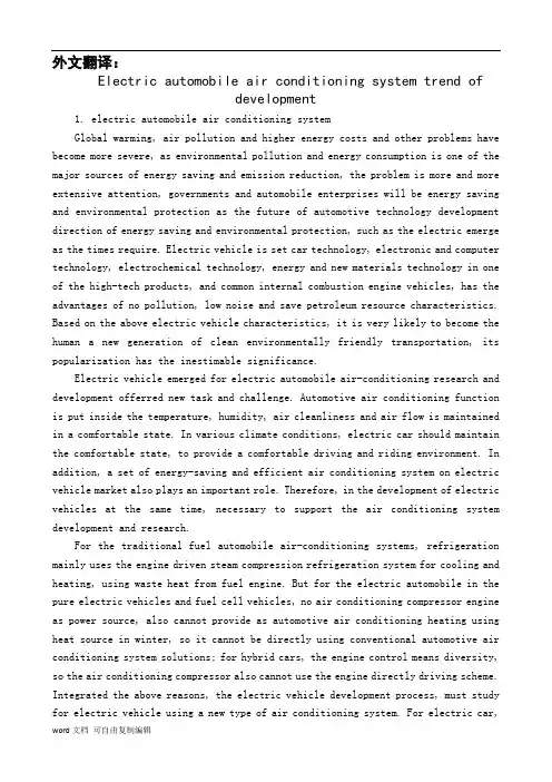
外文翻译:Electric automobile air conditioning system trend ofdevelopment1. electric automobile air conditioning systemGlobal warming, air pollution and higher energy costs and other problems have become more severe, as environmental pollution and energy consumption is one of the major sources of energy saving and emission reduction, the problem is more and more extensive attention, governments and automobile enterprises will be energy saving and environmental protection as the future of automotive technology development direction of energy saving and environmental protection, such as the electric emerge as the times require. Electric vehicle is set car technology, electronic and computer technology, electrochemical technology, energy and new materials technology in one of the high-tech products, and common internal combustion engine vehicles, has the advantages of no pollution, low noise and save petroleum resource characteristics. Based on the above electric vehicle characteristics, it is very likely to become the human a new generation of clean environmentally friendly transportation, its popularization has the inestimable significance.Electric vehicle emerged for electric automobile air-conditioning research and development offerred new task and challenge. Automotive air conditioning function is put inside the temperature, humidity, air cleanliness and air flow is maintained in a comfortable state. In various climate conditions, electric car should maintain the comfortable state, to provide a comfortable driving and riding environment. In addition, a set of energy-saving and efficient air conditioning system on electric vehicle market also plays an important role. Therefore, in the development of electric vehicles at the same time, necessary to support the air conditioning system development and research.For the traditional fuel automobile air-conditioning systems, refrigeration mainly uses the engine driven steam compression refrigeration system for cooling and heating, using waste heat from fuel engine. But for the electric automobile in the pure electric vehicles and fuel cell vehicles, no air conditioning compressor engine as power source, also cannot provide as automotive air conditioning heating using heat source in winter, so it cannot be directly using conventional automotive air conditioning system solutions; for hybrid cars, the engine control means diversity, so the air conditioning compressor also cannot use the engine directly driving scheme. Integrated the above reasons, the electric vehicle development process, must study for electric vehicle using a new type of air conditioning system. For electric car,the car has a high voltage DC power supply, therefore, the use of electric heat pump type air conditioning system, compressor with motor direct drive electric vehicle, become feasible solution.2.the characteristics of electric vehicle air conditioningElectric automobile air conditioner and common air conditioning device, electric vehicle air conditioning device and car environment has the following characteristics:①automotive air conditioning system mounted on a moving vehicle, to withstand the severe and frequent vibration and shock, requirements of electric vehicle air conditioning device structure in the various components should have sufficient resistance to vibration and impact strength and good sealing performance of the system;②electric car mostly short distance walking, riding in a relatively short time, plus electric car occupant space ratio, the heat generated is relatively high, relatively large heat load of air conditioning, refrigeration, heating and has the advantages of fast speed ability;③electric automobile air conditioning is the use of the car battery to provide DC power, the working efficiency of the compressor is high, control of high reliability, convenient maintenance;④automobile body heat insulation layer is thin, and doors and windows, large glass area, insulation performance is poor, electric car is no exception, resulting in serious car heat leakage;⑤ inside the facilities is rugged and seat, air distribution organization is difficult, difficult to achieve uniform airflow distribution.3.domestic and international current situation of the development of electric vehicle air conditioning① domestic electric car air-conditioning development statusThe early domestic electric car due to battery capacity constraints, in order not to affect electric vehicle mileage, most electric cars are not equipped with air conditioning system.With the domestic electric car gradually industrialization, marketization, electric vehicles must be equipped with air conditioning system. Due to the unique effects of electric vehicles to electric vehicles, the pure electric vehicles and fuel cell vehicles, no air conditioning compressor engine as power source, also cannot provide as automotive air conditioning heating using heat source in winter, domestic car manufacturers from the traditional fuel automobile air conditioner based onpartial replacement of design, will fuel the engine to drive the the compressor is replaced by a DC motor direct drive compressors, control corresponding change, to complete the refrigeration function, the replacement design effect to resolve the basic problem of electric automobile air-conditioning refrigeration, but the cooling efficiency to be improved. Due to the lack of fuel to the engine waste heat generated by heating, domestic manufacturers mainly use PTC heating and electric heating pipe, the heating mode can meet the heating effect, but these heating mode is hard on the consumption of electric vehicle battery power, the heating efficiency is relatively low, affect electric vehicle mileage.Air conditioning in the selection of the main parts, the current domestic electric car in addition to the compressor and control mode, the other main parts or the use of fuel automotive air conditioning parts, condensing equipment is mainly used to parallel flow condenser, evaporator is mainly used to laminated evaporator, throttle device is still a thermostatic expansion valve, a refrigerant is still R134a.According to the incomplete understanding, the domestic in developing electric vehicle manufacturers such as Chery, BYD,FAW, SAIC, JAC.the current electric vehicle air conditioning facilities basically similar, is in the development present situation.②current situation of the development of foreign electric vehicle air conditioningForeign electric automobile air conditioner development relative to domestic abroad is relatively mature, there is no lack of electric automobile air conditioner with domestic similar patterns, but in the heat pump electric automobile air conditioning already had certain foundation, Japan Honda pure electric cars use electric driven heat pump type air conditioning system, system has a built-in Reverse Converter Control compression pump. In addition, in very cold areas, some type of customers can be optional a fuel heater heating system.Japan electric ( DENSO ) company a few years earlier developed using R134a refrigerant electric car air-conditioning heat pump system, the heat pump system used in the car inside air condenser and evaporator structure. Electric ( DENSO ) Company in 2003also developed as a result of natural refrigerant COgood thermal physical2properties, Denso Japan company for electric car develops a set of COheat pump air2conditioning system, also used in the air duct system is arranged in the2heat exchanger, and R134a system is different when the system for refrigeration mode when the refrigerant flows through the condenser, and internal and external condenser.In order to reduce the air conditioning on battery power consumption, the UnitedStates of America Amerigon company developed air-conditioning seat, the chair is provided with a thermoelectric heat pump, heat pump action is through the need to regulate the temperature in space outside the water tank to transfer heat, thereby realizing the need to regulate the temperature of space refrigeration or heating. This kind of air conditioning seat in addition to energy saving but also can improve the driving, riding comfort, in electric vehicle supporting the use of suitable.Therefore, the foreign electric automobile air conditioner from energy efficient and practical breakthrough, domestic electric car air-conditioning industry should actively to study overseas advanced technology, draw lessons from, and on the basis of innovation breakthrough.4.the development trend of electric vehicle air conditioningElectric automobile driving energy from the battery, which is different from the traditional fuel automobile, made it to the air conditioning system also differed from the fuel of automobile air conditioner, as a drive source of energy for the limited battery capacity, the energy consumption of air conditioning system on electric vehicle mileage has bigger effect. Compared with cars, car air conditioning system energy saving and high efficiency raised taller requirement. At the same time, the electric car air-conditioning refrigeration, heating to solve two problems. According to the electric car special properties, the electric automobile air conditioner using thermoelectric ( I ) air conditioning system and electric heat pump type air conditioning system.1).a thermoelectric ( I ) electric vehicle air conditioning systemThe technology has many suitable for electric vehicles use characteristics, and with the traditional mechanical compression type air conditioning system compared, thermoelectric air conditioning has the following characteristics:① thermoelectric elements work to DC power supply;②change the direction of the current to generate refrigeration, heating the converse effect;③thermoelectric refrigeration piece of thermal inertia is small, cooling time is very short, the hot end heat well cold end load cases, energized in less than a minute, the refrigeration sheet can achieve the maximum temperature difference;④ component for regulating current size can adjust refrigeration speed and temperature, the temperature control precision can reach 0.001℃, and can easily realize the continuous regulating energy;⑤in the correct design and application conditions, the refrigerationefficiency can reach above 90%, and the heating efficiency is greater than 1;⑥ has the advantages of small volume, light weight, compact structure, reduces the electric vehicle kerb mass; high reliability, long service life and convenient maintenance; no moving components, therefore, no vibration, no friction, no noise and impact resistance.2).the heat pump type air conditioning system for electric automobileThe heat pump type air conditioning system on the original fuel car to be improved, the compressor is composed of permanent magnet brushless DC motor for direct drive, the system and the ordinary heat pump air conditioning system have no essential difference, as in electric vehicles, compressor and other major components has its particularity. And foreign heat pump technology has had certain foundation, the biggest advantage is that the refrigeration, heating efficiency is high, relevant enterprise development of full closed electric scroll compressor, is composed of a DC brushless motor drive, through the refrigerant return air cooling, with low noise, small vibration, compact structure, light weight etc.. In the test conditions for the environmental temperature of 40 degrees Celsius, the temperature inside the car is27℃,50% relative humidity conditions, when the system is stable it to1kW energy2.9kW refrigeration quantity; when the environmental temperature is - l0C, the temperature inside the car to25 DEG C,1kW can get the 2.3kW heating energy consumption. In the - l0℃to 40 ℃ under ambient temperature, both with high efficiency for electric vehicles to provide a comfortable driving environment. If the component technology is improved, the corresponding efficiency can also be improved.Based on the above mentioned, from air conditioning technology is mature and the sources of energy to use efficiency comparison, for thermoelectric ( I ) electric vehicle air conditioning system, the existence of thermoelectric materials, figure of merit is low, performance is not ideal, and the thermopile output by constitute a thermoelectric element element yield limit hoof. Does not have the electric automobile air-conditioning energy efficiency requirements. This makes the electric automobile air conditioner are more inclined to use energy efficient heat pump type air conditioner, the technical scheme for different types of motor vehicle has good commonality, and the vehicle structural change is small, is the future development trend of electric vehicle air conditioning.The heat pump type electric automobile air conditioner biggest weakness is the low temperature heating problems, especially in the northeast region, which is also the future of the industry research problem. In order to make the heat pump type electric automobile air conditioner more energy efficient, can from the followingaspects to solve:① to develop more efficient DC scroll compressor;②development control is more accurate, more energy-efficient silicon electronic expansion valve;③ using an efficient parallel flow condenser;④ improve microchannel evaporator structure, so that the refrigerant evaporates more uniform.In addition, the number of electric car door open and in driving by speed, light, speed and other factors, air conditioning heat load. The compressor and the air conditioning system to adapt to the change of condition factors, so the heat pump type air conditioning system for electric automobile variational design is particularly important.电动汽车空调系统发展趋势一、电动汽车空调系统全球气候变暖、大气污染以及能源成本高涨等问题日趋严峻,汽车作为环境污染和能源消耗的主要来源之一,其节能减排问题受到了越来越广泛的重视,各国政府和汽车企业均将节能环保当作未来汽车技术发展的指导方向,这样节能环保的电动也就应运而生。
Development of Integrated Motor Assist Hybrid System:Development of the ‘Insight’, a Personal Hybrid Coupe Kaoru Aoki, Shigetaka Kuroda, Shigemasa Kajiwara,Hiromitsu Sato and Yoshio YamamotoHonda R&D Co.,Ltd. Copyright ©2000 Society of Automotive Engineers, Inc.ABSTRACTThis paper presents the technical approach used to design and develop the powerplant for the Honda Insight, a new motor assist hybrid vehicle with an overall development objective of just half the fuel consumption of the current Civic over a wide range of driving conditions. Fuel consumption of 35km/L (Japanese 10-15 mode), and 3.4L/100km (98/69/EC) was realized. To achieve this, a new Integrated Motor Assist (IMA) hybrid power plant system was developed, incorporating many new technologies for packaging and integrating the motor assist system and for improving engine thermal efficiency. This was developed in combination with a new lightweight aluminum body with low aerodynamic resistance. Environmental performance goals also included the simultaneous achievement of low emissions (half the Japanese year 2000 standards, and half the EU2000 standards), high efficiency, and recyclability. Fullconsideration was also given to key consumer attributes, including crash safety performance, handling, and driving performance.1.INTRODUCTIONTo reduce the automobile’s impact on society and the environment requires that it be increasingly cleaner and more energy efficient. The issues of energy conservation, ambient air quality, and reduction in CO2 emissions are increasing raised as global environmental concerns. One solution for dealing with these issues is the hybrid automobile. Honda has developed and introduced to several major markets worldwide the Insight, a new generation of vehicle design. The Insight combines a hybrid power train with advanced body technology features to meet an overall goal of achieving the highest fuel economy practical.The hybrid power train is a motor assist parallel configuration, termed IMA for ‘Integrated Motor Assist’. This power train combines a highly efficient electric motor with a new small displacement VTEC engine, a lightweight aluminum body, and improved aerodynamics to realize 3.4L/100km (CO2:80g/km) on 98/69/EC fuel economy. Low emissions performance was also targeted with emission levels achieving the EU2000.In addition to recapturing deceleration energy, the integrated motor provides high torque assist during typical urban driving accelerations. This allows a significant reduction in engine displacement and higherengine efficiency. Sustained hill climbing performance and high speed cruising capability are assured by a power-toweight ratio of approximately 56kW per metric ton. New engine technology includes the application of a new VTEC (Variable valve Timing and valve lift, Electronic Control) cylinder head design promoting high efficiency and fast catalyst activation, and a new lean NOx catalyst system which promotes lean burn combustion and a reduction in emissions. Extensive friction and weight reducing features are also applied.2.DEVELOPMENT TARGETS AND CONCEPTDevelopment was aimed at the achievement of extremely low fuel consumption. We set a target of twice the fuel economy of the current production Civic, Honda’s representative high fuel economy car at 7.0 L/100km (93/116/ EC). As a result, the Insight has the lowest fuel consumption in the world, among gasoline passenger cars.Exhaust emission performance often tends to be sacrificed for the sake of low fuel consumption. However, we also decided to match the low emissions performance achieved by other mass production cars. Consideration was also given to recyclability (another important environmental issue), crash safety performance, and the basic car characteristics including handling and styling.Summarizing the above, our development targets were as follows:The best fuel consumption performance in the world∙Ultra-low exhaust emissions∙Superior recyclability∙The world's highest level of crash safety performance∙Advanced styling∙Practical features and responsive handling∙Comfortable two-seat configuration with personal utility space3.POLICIES FOR FUEL CONSUMPTION REDUCTIONIn order to establish the technical approach for achieving the fuel consumption target, we conducted a detailed analysis of the energy consumption of the base car, a Civic equipped with a 1.5 liter engine. We found that it was useful to divide the targeted efficiency gains roughly into thirds, as shown in Fig. 1, in order to achieve the low fuel consumption and numerous other above-mentioned goals. These divisions are as follows.∙Improvement of the heat efficiency of the engine itself∙Recovery of braking energy and employment of idle stop using a hybrid power plant∙Car body technologies including reduction of weight and reduced aerodynamic and rolling resistance.Figure 1. Target of double the fuel economy of CIVICAiming to establish a benchmark for 21st century automobile power trains, we developed this new Integrated Motor Assist power train. This power train simultaneously achieves both extremely low fuel consumption of 3.4L/100km, and low exhaust gas emission performance, befitting a next-generation car.This paper reports on the newly developed IMA system, including the lean burn engine, electric motor, power control unit, battery technology, and exhaust emission control technology used in the "Honda Insight". 4.AIM OF THE IMA SYSTEMWhile developing this next-generation IMA hybrid system, we incorporated as many currently achievable technologies and techniques as possible, in order to achieve the "world's lowest fuel consumption".The following four system development themes were established in order to meet this target.1.Recovery of deceleration energy2.Improvement of the efficiency of the enginee of idle stop system4.Reduction of power train size and weight5.OVERVIEW OF THE IMA SYSTEM5.1. SYSTEM CONFIGURATION –As shown in Fig. 2, the IMA system uses the engine as the main power source and an electric motor as an auxiliary power source when accelerating. Using a motor as an auxiliary power source simplifies the overall system and makes it possible to use a compact and lightweight motor, battery, and power control unit (PCU).Figure 2. IMA SystemA permanent magnet DC brushless motor is located between the engine and the transmission. When decelerating, the rate of deceleration is calculated for each gear and the PCU controls the motor to generate electricity (recover energy), which charges a nickel-metal hydride battery. When accelerating, the amount of auxiliary power provided (hereaftercalled "assist") is calculated from the throttle opening, engine parameters, and battery state of charge. The PCU controls the amount of current flowing from the battery to the drive motor5.2.RECOVERY OF DECELERATION ENERGY –Recoveringdeceleration energy through regeneration makes it possible tosupplement the engine’s output during acceleration and reduce theamount of fuel consumed. Reducing resistance due to runninglosses, including engine frictional losses, increases the availableenergy for regeneration. In particular, minimizing the enginedisplacement is an effective means of reducing friction. Enginedisplacement reduction also has several other benefits, such asweight reduction and increased thermal efficiency. The IMAsystem effectively increases the amount of regeneration duringdeceleration by optimizing the engine and transmissionspecifications.5.3.REDUCTION OF ENGINE DISPLACEMENT –Reducingengine displacement is a very important factor in improving fueleconomy of a hybrid drive train. However, modern automobileshave to perform over a wide dynamic range. Reducing thedisplacement is equivalent to lowering the basic performancecharacteristics of the car. As shown in the output characteristicsgraph in Fig. 3, the IMA system assists the engine in the low rpmrange by utilizing the hightorque performance characteristic of electric motors. The motor can increase overall toruque by over 50% in the lower rpm range used in normal driving. Output in the high rpm range is increased by using a Variable valve Timing and valve lift Electronic Control (VTEC) engine. Thus sufficient peak power is assured and makes it possible to use a new, small displacement 1.0 liter engine.Figure 3.Engine speed (rpm) Output performance of IMA SYSTEM Assist from the electric motor while accelerating is a very efficient means of reducing the amount of fuel consumed.5.4.ACHIEVING LEAN BURN ENGINE OPERATION –Assistfrom the electric motor, based upon the throttle opening, creates quite linear torque characteristics. This, in turn, improves driveability. In addition, motor assist is also provided undermoderate load conditions to broaden the lean-burn operating range, bringing out the full potential of the newly developed lean burn engine.5.5.IDLE STOP SYSTEM – Stopping the engine rather than idling atstops is also an effective means for reducing fuel consumption. In order to restart the engine with the minimum amount of fuel consumption, the engine is quickly cranked to 600 rpm or more by the hightorque integrated motor before ignition occurs, as shown in Fig. 4. This makes it possible to minimize the amount of fuel consumed, in addition to the fuel saved by not running the engine at idle.There are many issues to be considered when performing idle stop. These include judging the driver's intent to stop, preparing for the restart, providing a smooth feeling of deceleration, and minimizing vibration of the car body when the engine stops.Figure 4.Time (sec) The number of cranking in the engine startThis IMA system results in the achievement of both very quick restarts and exceptionally smooth starts.6.MOTOR ASSIST MECHANISM6.1. DEVELOPMENT OBJECTIVES –By limiting the IMA motor functions to assistance and regeneration, development themes were established to achieve the following two points.1.A simple and compact structure2.A system weight of 10% (80 kg) or less of the completed car weight 6.2. THIN PROFILE DC BRUSHLESS MOTOR – A thin and compact DC brushless motor with engine assist and energy regeneration functions was coupled to the engine crank-shaft (Fig. 5).Figure 5. Section view of MotorThis is a high efficiency, compact, and lightweight permanent magnet-type three-phase synchronous electric motor with a maximum output of 10 kW. In addition to developing technologies to reduce the weight and increase efficiency, we also aimed to make the motor as thinas possible in order to achieve a compact power train. Lost wax precision casting process was used for the rotor, rotating by bending coupled to the crankshaft. This achieves high strength and lighter weight (approximately -20%) compared with normal cast products. For the rotor magnets, further improvements were made to the neodymium-sintered magnets used in the HONDA EV PLUS, realizing approximately 8% greater torque density and improved heat resistance. This design also results in a motor structure that does not require a cooling system. A split stator structure with salient pole centralized windings was developed and used to reduce the motor axial width. A split stator was adopted to drive the rotor. This makes it possible to use the salient pole centralized windings, which are both more compact and efficient than the conventional coil wave winding method, as shown in Fig. 6. In addition, centralized distribution bus rings (Fig. 7) formed from copper sheets were used for the harness that supplies electricity to the coils on both sides of the stator. This results in an extremely compact and simple structure. These improvements achieve an extremely thin motor with a width of only 60 mm. This represents a 40% reduction in width compared to conventional technology.Wave winding Salient pole windingFigure 6. Compare of windingFigure 7. Cut view of Motor6.3. NICKEL-METAL HYDRIDE (NI-MH) BATTERY – A nickel-metal hydride battery is used to store and provide electrical energy for the motor assist. This is an advanced battery which has already achieved proven results in the high specific energy version used for the HONDA EV PLUS electric vehicle. The hybrid vehicle battery features stable output characteristics, regardless of the state-of-chargestatus. It is also extremely durable in this application. The battery pack has an integrated structure consisting of 20 modules, each having sixD-size cells connected in series, arranged in a lattice formation. These 120 1.2 V cells are all connected in series for a total battery pack voltage of 144 V.6.4. POWER CONTROL UNIT (PCU) –The PCU performs precise control of motor assist/regeneration and supplies power to the 12 V power source. It has built-in cooling functions, which give it a lightweight, efficient and compact structure. Significant weight reduction was achieved by integrating an air cooling system using highly efficient cooling fins and a magnesium heat sink case.The inverter for the drive motor, which is the most important component within the PCU, has switching elements integrated into a single module for generating the three-phase AC current. These were separate components on the EV PLUS. The drive circuit has been miniaturized and converted to an IC using high density integration. These improvements have resulted not only in significant weight reduction, but have also improved the power conversion efficiency. Further, using phase control to drive the motor at very high efficiencies reduces the amount of heat produced and makes it possible to use a lightweight and simple air-cooling system. (Fig. 8)Figure 8.Inverter Cut view of PCU Heat Sink case7.ENGINE7.1. DEVELOPMENT OBJECTIVES – The following four points were set as development themes in order to achieve low fuel consumption over a wide range of operating conditions.1.Improvement of thermal efficiency2.Reduction of mechanical losses (-10% compared with conventionaldesigns )3.Reduction of size and weight (lightest weight in its class)4. Achievement of half the EU2000 standards7.2.ENGINE OVERVIEW AND SPECIFICATIONS –The enginespecifications are shown in Table 1 and the main new features and their purposes are shown in Table 2.First, a displacement of approximately 1000 cm3 was considered optimal for this vehicle with the IMA system, so a 3-cylinder engine was selected to minimize combustion chamber surface-to-volume ratio andmechanical losses. (Fig. 9)7.3.FUEL CONSUMPTION – Engine displacement could be reduceconsiderably in the motor assist powertrain because of the motor assist enhancement of low rpm torque, and also VTEC for sufficient peak power output from the engine. A key feature of this engine is the significant improvement in combustion efficiency through lean burn technology. Technologies adopted to make this possible include new intake swirl ports, which enhance the swirl (mixture formation) inside the cylinders. A compact combustion chamber and a high compression ratio also help by improving the indicated heat efficiency. This result in significantly shorter combustion times compared to conventional lean burn engines, allowing combustion in a leaner range with a higher air-fuel ratio. This significantly improves the fuel consumption.The new high swirl ports and compact combustion chamber are evolutions based on conventional VTEC lean burn technology. In the conventional VTEC engine, swirl is produced by keeping one intake valve closed in low speed operating conditions. However, in this engine the intake valves and intake ports are arranged more vertically to produce strong eddies in the mixture flowing into the cylinders.The conventional VTEC configuration has the inlet and exhaust rocker arms each supported by a separate rocker shaft. The new VTEC mechanism shown in Fig.10 combines these into a single rocker shaft, thus realizing a significant reduction in size. In addition, it narrows the valve included angle from 46° to 30°, allowing a high swirl port shape and a very compact combustion chamber.Figure 9. Cutaway view of engineFigure 10. Section view of cylinder7.4.REDUCTION OF MECHANICAL LOSS –In addition toimprovement of the indicated heat efficiency, reduction of mechanical loss is also important to improve fuel economy. To achieve this, the following the low friction technologies were used.∙Roller coaxial VTEC mechanism∙Piston micro-dimple treatment∙Offset cylinder structure∙Low tension piston rings∙Carburized connecting rodsThe roller coaxial VTEC structure (Fig. 11) is an adaptation of technology used in the Honda S2000 (high output sportscar engine) to a single-cam VTEC mechanism. The camshaft drive loss was reduced by 70% using a needle roller bearing in the area where the rocker arm slides on the camshaft. In addition, simultaneous reduction in both weight and size were achieved by incorporating the VTEC switching piston into the roller bearing inner shaft.Piston micro-dimple treatment consists of treating the surface of the piston skirt to create a micro-dimple surface. This increases the oil film retention performance and can reduce friction by approximately 30% when lowfriction oil is used.Figure 11. Section view of Roller VTECThese effects resulted in the development of a 0W-20 grade low viscosity oil that complies with ILSAC standards. The friction reducing effects of super-low viscosity oil were measured by engine motoring. These measurement results are shown in Fig. 12. In the current technology engine, the HTHS viscosity at the limit friction value was approximately 2.5 mPas. Being used together with the advanced low friction engine, the limit value was lower than the current technology engineThese low friction technologies have vastly reduced the overall engine friction, as shown in Fig. 13. In total, they have realized a reduction in friction of 10% or more compared to a conventional 1.0 liter engine design .Figure 12. Limit in friction reductionFigure 13. Engine friction7.5.WEIGHT REDUCTION – The structure and materials of almostall parts in this engine have been reviewed with the aim of creating the lightest engine in the world in the 1.0 liter class. This weight reduction extends even to the "skeleton structure technology" and "materials technology" fields carburized connecting rods as used on the S2000 (high output sportscar engine). Carburization strength enhancement technology contributes greatly to increasing engine operational speed. We applied this strength enhancement technology to create a slim connecting rod design for the IMA engine. This resulted in a weight reduction of approximately 30% compared to conventional connecting rods.Most oil pans are made of steel plate or aluminum alloy. Conventionalmagnesium materials have had problems withstanding the high temperatures of engine oil. In contrast to conventional materials, which experience a significant drop in creep strength at 120°C or higher, we have developed a new magnesium oil pan (Fig. 14) which ensures sufficient creep strength up to 150°C.Figure 14. Magnesium Oil PanThis oil pan is fastened using steel bolts with aluminum washers to prevent galvanic corrosion. The oil pan weight is 35% lighter than an aluminum oil pan, for a reduction in weight that is comparable to the ratio between the specific masses of the two metals.In order to expand the application of plastic parts, plastic materials were adopted for the intake manifold, cylinder head cover, water pump pulley, and intake system parts. These changes brought the discrete dry weight of the engine to less than 60 kg, which is the lightest weight in the world for the 1.0 liter class.7.6.EXHAUST EMISSION PERFORMANCE –Technology forsimultaneously achieving both lean burn and low exhaust emissions was adopted in this engine, achieving a notable reduction in NOx emissions.Combustion was improved by putting the exhaust system to the rear of the engine (Fig. 15). In addition, the exhaust manifold was integrated with the cylinder head and a NOx adsorption catalyst which reduces NOx emissions during lean burn operation was also newly developed.Figure 15. Section view of emission system7.6.1. Integrated Exhaust Manifold and Cylinder Head – Conventional cylinder heads have independent exhaust ports for each cylinder and a separate exhaust manifold acts to converge these exhaust ports into a single port is then mounted to the head. However, the new head on the Insight has a structure which converges the exhaust ports into a single port inside the head, as shown in Fig. 16. This greatly reduces the weight. In addition, the small heat radiating surface area reduces the exhaust gas heat loss, thus enabling early catalyst activation.Figure 16. View of Head7.6.2. Lean NOx Catalyst – The catalyst system on the Insight combinesa conventional three-way catalyst with NOx adsorbing materials. The NOx conversion mechanism of the newly developed catalyst is shown in Fig. 17. The NOx in the exhaust gas is adsorbed and separated by the NOx adsorption action of the catalyst during lean engine operating conditions. Conventional three-way catalyst operation reduces part of the NOx to nitrogen and oxidizes most of the HC and CO to CO2 and H2O during lean operation. However, since the exhaust gas contains large amounts of oxygen, there is relatively little NOx reduction with the three-way catalyst and most of the NOx is stored on the surface of the adsorbing material. When the exhaust is held at the theoretical air fuel ratio (stoichiometry) or richer air-fuel ratio, the adsorbed NOx is reduced to nitrogen using HC and CO as reducing agents. The adsorbent is regenerated at the same time. Thus, NOx, HC and CO are effectively converted using the three-way catalytic action of the catalyst combined with the NOx adsorber.This type of catalyst exhibits superior conversion performance during both lean operation and stoichiometric operation by switching betweenlean and stoichiometry operating conditions. It is essential to create a regenerative atmosphere before the NOx adsorption capacity becomes overloaded. This catalyst directly adsorbs NOx during lean burn engine operation and the adsorbed NOx is then reduced and exhausted as harmless nitrogen (N2) during stoichiometric operation.Figure 17. Exhaust gas purification mechanismThis catalyst is characterized by the direct adsorption of NOx to the catalyst surface during lean operation. Adsorption on the catalyst surface, instead of absorption as a compound inside the surface, facilitates conversion during reduction and also provides superior durability at high temperatures. This adsorptive type catalyst reduces NOx emissions during lean burn operation to 1/10 the level of the conventional three-way catalyst. It should be noted that the adsorption and conversion performance of this type of catalyst is sensitive to sulfur levels in the fuel, as sulfur can compete for the active NOx adsorbing sites. As a conventional three-way catalyst has virtually no NOx reduction during lean-operation, the lean burn operating range typically has to be reducedto keep NOx emissions down. Use of an adsorptive type catalyst maintains the full lean burn range and improves fuel economy, even while reducing NOx.This vehicle can also satisfy the EU2000 standards, making this a highly efficient lean burn engine that complies with exhaust emissions standards throughout the world.8.CONCLUSIONThis paper presents a general overview of the recently developed motor assist hybrid powertrain, as well as a description of its various components and its output and emission performance. This hybrid power train simultaneously achieves ultra low fuel consumption and low exhaust emissions. It also achieves a compact, lightweight power train layout. We believe this system advances 21st century automotive technology toward regional and global environmental goals. REFERENCES1.Aoki, Kaoru, et al.: "Development an Integrated Motor Assist HybridSystem", JSAE No. 98-99 1612.Yamaguchi, Tetsuro: "CVT Control in the HONDA Hybrid 'IMA'",No. 9908 JSAE SYMPOSIUM, Latest Motive Power Transmission Technologies '99, p.37403.Ohno, Hiroshi, et al.: "Development of a NOx Adsorptive ReactionType Three-Way Catalyst", HONDA R&D Technical Review, V ol. 11No. 2 (October 1999), p.45-504.Fukuo, Koichi, et al.: "Development of the Ultra Low FuelConsumption Hybrid Car 'Insight'", HONDA R&D Technical Review, V ol. 11 No. 2 (October 1999), p.1-85.Hideki Tanaka, et al .: "The Effect of 0W-20 Low Viscosity EngineOil on Fuel Economy”, SAE Paper No.1999-01-3468,Fuels and Lubricants meeting and Exposition, Toronto, Ontario, Canada, October 1999.6.Aoki, Kaoru, et al.: "An Integrated Motor Assist Hybrid System",SAE Paper No.2000-01-2059, Government / Industry Meeting, Washington, D.C., USA。
Mark Steffka, B.S.E., M.S., is with the Electromagnetic Compatibility (EMC) Engineering Group of General Motors (GM) Pow ertrain and is a faculty member of two universities in the Detroit, Michigan, area. He has over 25 years of industry experience in the design, development, and testing of military, aerospace and automotive electronics, including power, control, and radio frequency (RF) systems. Since 2000, he has been an adjunct lecturer at the University of Michigan-Dearborn, in the Electrical and Computer Engineering (ECE) department for the undergraduate and graduate classes on EMC, and was a Co-Principal Investigator for a United States’ National Science Foundation grant which resulted in the establishment of the campus’ EMC laboratory. For the college’s Engineering Professional Development office he is the instructor for engineering continuing education courses on “Automotive EMC” and “Antennas”. He is the recipient of faculty and alumni awards from the University of Michigan – Dearborn, College of Engineering and Computer Science, for his contributions to engineering education and the EMC curriculum. At the University of Detroit –Mercy he is an adjunct professor and teaches an undergraduate and graduate engineering course on EMC. He is a member of Institute of Electrical and Electronics Engineers(IEEE), has served as a session chair for the IEEE EMC Symposium and a technical session organizer for the Society of Automotive Engineers (SAE) World Congress. He has been a speaker at IEEE and SAE conferences held in the United States and international locations.His publications have covered topics on EMC, RFI, and was a co-author of the book“Automotive Electromagnetic Compatibility”. He has held an amateur radio license since 1975, with the call sign WW8MS, is a Life Member of ARRL, the National Association for Amateur Radio, and serves on the ARRL EMC Committee.马克Steffka,疯牛病,硕士,是与电磁兼容性(EMC)工程集团,通用汽车(GM)的动力,是两个在密歇根州底特律地区的大学任教。
On the vehicle sideslip angle estimation through neural networks:Numerical and experimental results .S. Melzi , E. SabbioniMechanical Systems and Signal Processing 25 (2011): 14〜28电脑估计车辆侧滑角的数值和实验结果S.梅尔兹,E.赛博毕宁机械系统和信号处理2011年第25期:14~28将稳定控制系统应用于差动制动内/外轮胎是现在对客车车辆的标准(电子稳定系统ESP、直接偏航力矩控制DYC )。
这些系统假设将两个偏航率(通常是衡量板)和侧滑角作为控制变量。
不幸的是后者的具体数值只有通过非常昂贵却不适合用于普通车辆的设备才可以实现直接被测量,因此只能估计其数值。
几个州的观察家最终将适应参数的参考车辆模型作为开发的目的。
然而侧滑角的估计还是一个悬而未决的问题。
为了避免有关参考模型参数识别/适应的问题,本文提出了分层神经网络方法估算侧滑角。
横向加速度、偏航角速率、速度和引导角,都可以作为普通传感器的输入值。
人脑中的神经网络的设计和定义的策略构成训练集通过数值模拟与七分布式光纤传感器的车辆模型都已经获得了。
在各种路面上神经网络性能和稳定已经通过处理实验数据获得和相应的车辆和提到几个处理演习(一步引导、电源、双车道变化等)得以证实。
结果通常显示估计和测量的侧滑角之间有良好的一致性。
1介绍稳定控制系统可以防止车辆的旋转和漂移。
实际上,在轮胎和道路之间的物理极限的附着力下驾驶汽车是一个极其困难的任务。
通常大部分司机不能处理这种情况和失去控制的车辆。
最近,为了提高车辆安全,稳定控制系统(ESP[1,2]; DYC[3,4])介绍了通过将差动制动/驱动扭矩应用到内/外轮胎来试图控制偏航力矩的方法。
横摆力矩控制系统(DYC )是基于偏航角速率反馈进行控制的。
摘要本文主要研究轻型汽车前独立悬架的设计分析方法以及轮胎磨损与悬架运动、前轮定位参数的关系。
首先对双横臂独立悬架的各主要组成部件如减振器的选型设计、横向稳定杆的设计校核、扭杆弹簧设计以及对双横臂式和麦弗逊式独立悬架的运动进行了分析,提出了相应的计算方法,编制了一套具有一定实用价值的前独立悬架设计分析软件。
并且采用前轮定位仪,进行了实验验证。
论文对双横臂独立悬架参数提出以减小轮胎磨损为优化目标,进行了优化设计。
提出了通过优选、调整悬架初始位置状态,以及优化确定转向横拉杆断开点位置的方法,来减小轮胎磨损。
同时采用正交实验的方法分析了双横臂独立悬架各结构参数和安装参数对悬架性能和轮胎磨损的影响,确定出最大的影响因素及次要因素。
然后从轮胎模型入手分析前轮定位参数同轮胎磨损的关系。
以轮胎磨损能量作为评价指标,选取刷子轮胎模型,对轮胎在稳态纵滑状态下、稳态纵滑侧偏状态下和边界条件下的轮胎磨损进行了分析研究,确定了量化模型。
并以轮胎侧偏角为中间变量,建立了前轮定位参数同轮胎磨损之间关系的数学模型,进行了计算机仿真计算。
从而可对悬架进行进一步的优化设计,以减小对轮胎磨损的影响,提高车辆的行驶性能和使用经济性。
关键词:汽车;独立悬架;轮胎磨损;定位参数悬架系统原理Kaoru Aoki, Shigetaka Kuroda, Shigemasa Kajiwara, Hiromitsu Sato and Yoshio YamamotoHonda R&D Co.,Ltd.悬架系统虽不是汽车运行不可或缺的部件,但有了它人们可以获得更佳的驾驶感受。
简单的说,它是车身与路面之见的桥梁。
悬架的行程涉及到悬浮于车轮之上的车架,传动系的相对位置。
就像横跨于旧金山海湾之上的金门大桥,它连接了海湾两侧。
去掉汽车上的悬架就像是你做一次冷水潜泳通过海湾一样,你可以平安的渡过整个秋天,但会疼痛会持续几周之久。
想想滑板吧!它直接接触路面你可以感受到每一块砖,裂隙及其撞击。
2010China International Automobile Manufacturing and Producing Facility ExpositionPreparation time: October 26-28, 2010Book booth Area: China International Exhibition Center (Old Hall)Theme: Gathering of Finest Facilities Origin of High-quality AutomobilesTotal Exhibition Area: 27,000m2Number of exhibitors: 600 exhibitors come from 30 countries and regions Number of audiences: 12,000 audiences from 60 countries and regionsExhibits Profile:Automotive Manufacturing: metal cutting, stamping casting and forging, welding and cutting,coating technologies and painting, assembly, monitoring and inspection, testing and experiments, automation and drives, logistics and supply chain, information technology, design and development, materials, heat treatment, new products.Parts Machining: Automotive parts and components processing of metal cutting, grinding, milling, drilling, machine tool equipment; stamping, forging, bending technology and equipment; automotive interior parts cutting, cutting, polyurethane foam technology and equipment; engine manufacturing plane equipment, measuring equipment; gear machining and bearing special equipment, laser cutting, marking technology and equipment, numerical control cutting tool, coating technology, metal processing oil.New energy, environmental protection, energy-saving technology equipment and products of automobiles;Schedule:Preparation time: October 24-25, 2010Opening ceremony: 10:00 AM October 26, 2010Opening time: October 26-28, 2010Move-out time: 16:00 PM October 28, 2010Cost of Exhibition:(Pairs of opening booths, plus 10%)Section A: Standard booth ¥16800/9 m2Section B:Standard booth ¥13800/ 9 m2Section C: Standard booth ¥9800/ 9 m2Indoor Ground(36m2 on hair):¥1280/ m2Same time activities: symposia, face-face trade fair,purchase introduction and products introduction.Sponsoring Units:China Council for the Promotion of Intermational Trade Authorization Unit:China International Economic and Technical Cooperation Consultants IncOrganization Unit:China International Economic and Technical Cooperation Consultants IncUndertaken Unit:China International Economic and Technical Cooperation Consultants IncDongdu International Exhibition (Beijing) Co., LtdSupport Unit:China Automotive Industry AssociationChina Society of Automotive EngineeringOfficial media:Automobile Manufacturing and Production Facility Exposition Exposition on-line:Exhibition contact:Room 1002,Floor 10,Nan Li Shi Lu 66, Xicheng District, Beijing, Postal Code100045 Telephone number:Tex number:Contact person:E-mail:Report after China International Automobile Manufacturing and Producing Facility ExpositionOverview of CIAMPFE:2009 China (Beijing) International Automobile Manufacturing and Producing Facility Exposition (CIAMPFE) has succeed in China(Beijing)International Exhibition Center from November the11th to13th. It received a positive response from the community and broad participation.China Automotive Industry Association and China Society of Automotive Engineering authoritative organizations expressed its support. The United States, Japan, Germany,Britain, South Korea, India, Belgium, Poland, Turkey and other countries embassy officials gave a high degree of attention and support, and they will continue to participate in next year's exposition.Scale of CIAMPFE:Influenced by the financial crisis, the first CIAMPFE covers a floor space of about 22000 square meters as planned, but the actual area is 14600 square meters . More than 268 exhibitors, including 39 enterprises are special equipment booth, which cover 6182 square meters, accounting for about 42.34% of the total area of the exhibition area.At the same time,three-days symposia, face-face trade fair,purchase introduction and products introduction meeting were held. It makes exhibitors and visitors got better communication and cooperation.Audiences of CIAMPFE:More than thirty companies were invited to visit: Germany's BMW, Beijing Benz - Daimler-Chrysler, Beijing Automotive Holdings, Beijing Hyundai, Beijing Foton, SAIC, Changchun FAW, Guangzhou Automobile Group, BYD Auto of Shenzhen, Yunnan Hongta, Chery of Anhui, Hebei Great Wall Motor, Tianjin Xiali, Zhejiang Geely Group, Hafei Motor, Zhengzhou Yutong, youth Automotive Group, Dongan Auto, Auman heavy-duty vehicles, Beijing Automotive Research Institute, the China Auto Parts Industry Company,No.1 Group of China Aviation Industry Corporation, China North Vehicle Research Institute, China Shipbuilding Industry, No.1 Group of China Tractor , South Korea Incheon, South Korea Ching Industrial Co., Ltd., Bosch, Denso Corporation, Delphi Corporation, Magna Group, Beijing Automotive Li Er, Dongfeng auto parts, Wuhu Lingyun Industrial, Central power, the United States and Germany auto parts and so on. In addition to the media and some exhibition counterparts, above 98% are professional visitors.Fen Xuehong, Purchasing Manager of BMW Automobile Co., LTD. said, "for the high-quality exhibitors, organizer's invitation is very professional.Such scale of automobile manufacturing industry chain is the first case in the international exhibition. Particularly it has brought new technologies and products for the automobile manufacturing technology and equipment, etc."Mao Dehe, Vice-president of Shenzhen BYD Auto Co., Ltd. Said, "all aspects of the exposition is good. After 3-day visit, I saw the advanced technology and equipment on international and domestic automobile manufacturing field , and the rapid development of domestic automobile manufacturing equipment and technology. On behalf of the industry's highest grade, there are international leading-edge technology and products on the exposition, it gives us China's own brand carmakera great harvest."Exhibitors' Experience:David Wang, the Sales Manager of IPG (Beijing) Fiber Laser Technology Co., Ltd. affirmed the professionalism of the exhibition, and said he will participate the next exposition, and had been booking an exhibition booth .Hao Gepp Ruite, director of Germany Wolf Group Asia District, accept CCTV network reporters said, "Although the exposition affected by the weather, exhibitors and spectators are not too much. The automobile industry for the ordinary people are not closely related, but the industry still come to visit. To enhance the Wolf Group's reputation in the industry, and we will continue to participate in next year's exposition. "Wu Wenzhi, executive director of South Korea's POSCO Specialty Steel Co., Ltd.received a number of media interview and said “CIAMPFE will expand Chinese market as anopportunity.”Li Lei, Sales Manager of Beijing High-tech Electrical and Mechanical Co., Ltd. accept CCTV interview, said: "The purpose of attending the exhibition is promoting products and expanding market share. CIAMPFE has clear conception and very professional. We believe that the organizer has applied good service. I hope the exposition will enlarge the scale and we can participate in next year's exhibition.China Daheng (Group) Co., Ltd.with a low-key appearance standard booths, but still attracted a lot of professional audience. The General Manager Jiang Zhengmin of Laser Engineering Branch contended frankly: Although the scale is not large, there is still a good harvest.Achievement of CIAMPFE:On-site turnover:¥61.78 millionAudiences number:7712Contract value:¥185,000,000Professional of the exhibitors:100%Professional of the audiences:98.68%Media index:0.42%2010年中国国际汽车制造及生产设备展览会准备时间:10月26-28,2010预订展位面积:中国国际展览中心(老馆)主题:最好的设施收集原产地高品质的汽车总展览面积:27,000平方米参展商数量:来自30个国家和地区600家参展商观众人数:12000来自60个国家和地区的观众展品范围:汽车制造:金属切削,冲压铸件和锻造,焊接和切割,涂装技术和涂装,总装,监督和检查,测试和实验,自动化和驱动器,物流及供应链,信息技术,设计和开发,材料,热处理,新产品。
W ORLD T RADE O RGANIZATION WT/DS155/10 31 August 2001 (01-4175)ARGENTINA – MEASURES AFFECTING THE EXPORT OF BOVINE HIDES AND THE IMPORT OF FINISHED LEATHERArbitrationunder Article 21.3(c) of theUnderstanding on Rules and ProceduresGoverning the Settlement of DisputesAward of the ArbitratorFlorentino P. FelicianoWT/DS155/10Page 1I.Introduction1.On 16 February 2001, the Dispute Settlement Body (the "DSB") adopted the Panel Report1 in Argentina –Measures Affecting the Export of Bovine Hides and the Import of Finished Leather ("Argentina – Hides and Leather").2 At the DSB meeting of 12 March 2001, Argentina informed the DSB, pursuant to Article 21.3 of the Understanding on Rules and Procedures Governing the Settlement of Disputes (the "DSU"), that it would implement the recommendations and rulings of the DSB in this dispute and that it would require a "reasonable period of time" to do so, under the terms of Article 21.3 of the DSU.2.In view of its inability to reach an agreement with Argentina on the period of time reasonably required for implementation of those recommendations and rulings, the European Communities requested that such period be determined by binding arbitration pursuant to Article 21.3(c) of the DSU.33.By joint letter of 12 June 2001, Argentina and the European Communities notified the DSB that they had agreed that the duration of the "reasonable period of time" for implementation should be determined through binding arbitration, under the terms of Article 21.3(c) of the DSU, and that I should act as Arbitrator.4 The parties also indicated in that letter that they had agreed to extend the time-period for the arbitration, which shall be completed no later than 90 days after the date of the appointment of the arbitrator.5 Notwithstanding this extension of the time-period, the parties stated that the arbitration award would be deemed to be an award made under Article 21.3(c) of the DSU. My acceptance of this designation as Arbitrator was conveyed to the parties by letter of 12 June 2001.4.Written submissions were received from Argentina and the European Communities on 3 July 2001, and an oral hearing was held on 18 July 2001.II.Arguments of the PartiesA.Argentina5.Argentina requests the arbitrator to fix the "reasonable period of time" at forty-six months and fifteen days, so that that period of time will expire on 31 December 2004.1WT/DS155/R, WT/DS155/R/Corr.1.2WT/DS155/5.3WT/DS155/6.4WT/DS155/8.5Ibid.WT/DS155/10Page 26.Argentina submits that the text of Article 21.3(c) of the DSU makes it clear that the 15-month period provided as a guideline is merely indicative. Article 21.3(c) speaks of the possibility of fixing a period of longer than 15 months for the implementation of the recommendations and rulings of the DSB. According to Argentina, the circumstances in this particular dispute warrant the granting of a period longer than 15 months for the implementation of the DSB recommendations and rulings.7.Since 1992, Argentina has been working on a programme to combat tax evasion and reform its tax system. The cornerstone of this programme is the system of percepciones and retenciones applied to the Impuesto al Valor Agregado (the "IVA") and the Impuesto de Ganancias (the "IG"). This programme ties in, both economically and legally, with the objective of reducing the fiscal deficit. The programme has been explicitly backed by various international financial agencies, in particular, the International Monetary Fund (the "IMF"). The agreements concluded with the IMF set out a number of quantitative targets, notably for the levels of fiscal deficit, primary spending and public debt, that are monitored on a quarterly basis throughout the period covered by the programme. Failure of Argentina to achieve these targets would preclude disbursement of the funds otherwise available under the agreements.8.Argentina stresses that its fiscal position has seriously deteriorated over the past years, essentially as a result of the fall in tax revenue brought about by the economic recession that began in the third quarter of 1998 in the wake of the 1997 "Asian crisis". In this context of economic recession, Argentina sought to reduce the deficit by increasing taxes, and reducing primary spending. These efforts must continue this year and over the next few years.9.Under these circumstances, Argentina argues that legal and fiscal difficulties would result from eliminating the extra financial burden imposed on importers as a result of the advances on the IVA and IG at rates higher than those applied to domestic transactions, through a "downward equalization" of the rates applied to imports.10.Argentina, at the same time, contends that although in theory it would be possible to comply with the findings of the Panel through an "upward equalization" of the rates of the said payments on account, that is, by increasing the rates for domestic transactions, the effects of such a measure on Argentina's current situation, when the country is trying to recover from recession, would make the measures politically and economically unfeasible. Similarly, the introduction of a system of refunding interests to importers, would involve setting up a very complex administrative mechanism to ensure accurate calculation of interest due. Moreover, it would open the door to complaints from the relevant domestic sectors, complicating further the fiscal situation.WT/DS155/10Page 311.Argentina submits that the structure of its tax system justifies the requested time-limit. Under Argentina law, there is a set of regulations governing the conditions and time-limits for action by the national authorities in the domestic sphere. In the external sphere, there is a set of payment obligations and commitments assumed by Argentina that can only be honoured by strict compliance with the laws in force: the National Budget Law No. 25,401 of 12 December 2000 and the Fiscal Solvency Law No. 25,152 of 15 September 1999.12.Argentina describes the process by which its annual budget is enacted as follows. In September of each year, the Executive submits to the Congress of the Nation its draft budget for the following financial year, containing estimated income and expenditure authorizations. First, it is examined by the Budget and Finance Committee of the Chamber of Deputies. Once that Committee has issued its opinion, the draft budget is examined by the Chamber, and upon approval by the Chamber of Deputies, it is passed on to the Budget and Finance Committee of the Senate before final transmission to the Senate. When it has been approved by both Chambers, it is promulgated by the Executive, which has partial veto authority. Once this process has been completed, the National Budget becomes a Law of the Nation, and can be amended only by another national law.13.The text of the law is accompanied, inter alia , by a number of annexed tables providing a breakdown of the budgetary information (income, expenditure, financing, etc.) according to the organization of the national administration and its decentralized bodies. The tax revenue forecast is broken down according to the different taxes (IG, IVA, Personal Property Tax, etc.) and set out in detail in the Executive's annual letter of submission to the National Congress.14.The projected amounts are then incorporated in the final estimate of income that is ultimately approved by Congress. The specification of these amounts, once they are included in the budget, forms part of the Law and make up the estimate of income for the entire financial year; in other words, they can only be amended by another law, since any change would involve a consequential change in the expenditure/income equation and the deficit level already approved.15.Argentina further explains that, at the same time, the tax system is tied to the Law on Fiscal Solvency which provides, inter alia, for the progressive reduction of the national public deficit with a view to balancing the budget by 2005. This Law establishes target deficit levels for each year, and any change in the deficit levels indicated would also require a legislative amendment. Because of the relationship between the Law on Fiscal Solvency and the Budget Law, estimated income and expenditure will have to be adjusted in order to reduce the deficit to attain the target prescribed. The procedure will have to be applied by law in each of the succeeding financial years until the process is completed in 2005.WT/DS155/10Page 416.The Law on Fiscal Solvency also lays down the obligation to include in the letter of submission of the annual budget a multi-year budget covering at least three years. In other words, the Executive must submit to the Congress, together with the budget for the coming year, a multi-year projection containing estimates of income on the basis of existing tax rates which means calculating the advances in the form of retenciones and percepciones needed in order to meet the objectives of the Law on Fiscal Solvency for 31 December 2004.17.As a result, in the view of Argentina, it is not possible to amend the budget currently in force without altering its deficit target as well as the deficit target of the Law on Fiscal Solvency. Nor is it possible, in the current situation, to alter the system of customs levies. That system is not only linked to imports, but is also part of a comprehensive scheme to combat tax evasion which includes levies on purchases in the domestic market and the retenciones regime. The system makes it possible to maintain better monitoring of the obligations of taxpayers while providing them with adequate incentives to declare and regularize their operations.18.Argentina believes that a single and immediate modification of this regime involving a reduction of the rates of levies on imports would clash with the objective of the Law on Fiscal Solvency, since it would involve a significant loss in tax revenue. Moreover, the agreement in force with the IMF provides for reduction in the deficit over the next few years in line with the Law on Fiscal Solvency. This agreement is binding on the Argentine Government, is currently in force, and specifically takes up the deficit reduction commitments contained in the Law on Fiscal Solvency. Any amendment to the IMF agreement would require renegotiation, and the fiscal targets are determined in compliance with the Law on Fiscal Solvency.19.The Argentine public debt structure includes commitments for short, medium and long-term interest and capital payments. Argentina undertook a major debt equity swap in order to ease the burden imposed by the sequence of debt maturities. Having conducted this swap, it is particularly important in view of the rescheduling of maturities, involving a considerable medium-term fiscal cost, to ensure solvency during the stage covered by the Law on Fiscal Solvency extending up to 2005.20.Argentina submits that Article 21.2 of the DSU, which speaks of "interests" of developing countries, ties in with the general provisions of Article 21.3(c). The "particular circumstances" of Argentina in this case are a combination of legal obligations that can only be amended through an act of the National Congress, as in the case of the Budget Law and the Law on Fiscal Solvency, and of international obligations such as the IMF commitments.21.Argentina recalls that according to past arbitral awards, Article 21.2 of the DSU "… enjoins, inter alia, an arbitrator […] to be generally mindful of the great difficulties that a developing countryWT/DS155/10Page 5Member may, in a particular case, face as it proceeds to implement the recommendations and rulings of the DSB."6In the present case, Argentina's economic interests as a developing country and its fiscal solvency are at stake. This is clearly reflected in the capital debt maturity schedule throughout the period requested as a reasonable period of time (up to 2005). Likewise, owing to the size of the debt involved, and in particular to the impact of any failure to comply with the IMF Agreement, Argentina would have great difficulty financing an increase in its budget deficit.22.Argentina maintains that the impact of any change in the rates would be significant. The retenciones and percepciones are a fundamental element in maintaining an adequate tax collection level. Through this mechanism, $1,600 million were collected in 2000, i.e. more than 18 per cent of the total taxes collected in connection with foreign trade. During the same year, IVA and IG collected at customs accounted for more than 7 per cent and 6 per cent respectively of the total amount collected for each tax. To cushion the impact of this loss of revenue, a procedure involving progressive equalization sector by sector is necessary. Argentina's "interest" as a developing country, therefore, consists in avoiding an abrupt implementation without a transition period, in the space of a single financial year, that would jeopardize the objective of reducing the deficit.23.Against the foregoing background, Argentina, requests that consideration be given to its "interest" in being granted a period of time that would enable it to implement the recommendations and rulings of the DSB in this dispute "progressively", (i.e., by instalments, as it were) over a period of three financial years beginning in 2002 and ending on 31 December 2004.B.The European Communities24.The European Communities notes that the measures in dispute are contained in a series of Resoluciones Generales issued by the Dirección General Impositiva (the "DGI"). In 1997 the DGI was merged with the Dirección General de Aduanas in order to create the Administración Federal de Ingresos Público s (the "AFIP"). The AFIP is an "autarchic entity", which operates autonomously, under the general supervision and control of the Minister of Economy. The Chief of the AFIP is empowered to issue new Resoluciones Generales and to amend existing ones.25.The European Communities submits that in order to comply with the recommendations and rulings of the DSB, Argentina must take one of the following actions: equalize the rates applied to imports and to internal sales (including the zero rates); and/or provide for the refund to the importers of the additional costs imposed by the higher rates on imports, or establish a similar compensation6Award of the Arbitrator under Article 21.3(c) of the DSU, Chile –Taxes on Alcoholic Beverages ("Chile – Alcoholic Beverages"), WT/DS87/15, WT/DS110/14, 23 May 2000, para 45.WT/DS155/10Page 6system. The above actions will require, respectively, amending the existing Resoluciones Generales or adopting new ones.26.The European Communities observes that the adoption or amendment of a Resolución General of the AFIP does not have to follow any pre-determined procedural steps, other than the prior consultation (intervención) of two administrative units of the AFIP. Nor are they subject to any deadlines, whether mandatory or voluntary. The Resoluciones Generales can be enacted or amended within a short time frame and, in practice, are issued very frequently.27.The latest amendment of Resolución General No. 3431/91 is contained in Resolución General No. 1021/2001 of 7 June 2001, which lowers the rate of the advance IVA on imports of capital goods to 5 per cent. The reduction of the IVA rate on capital goods was decided for general reasons of economic policy. Nevertheless, according to the European Communities, the ensuing reduction of the advance IVA rate on imports of those products has had the incidental effect of partially removing one of the GATT inconsistent aspects of the measures in dispute. This shows that it is practicable for the AFIP to take the type of measures that would be required for complying with the other DSB's recommendations within an equally short time frame.28.Article 21.1 of the DSU states the general principle that "prompt compliance with recommendations or rulings of the DSB is essential in order to ensure effective resolution of disputes to the benefit of all Members". This obligation is elaborated in Article 21.3 of the DSU, where it is stipulated that "[i]f it is impracticable to comply immediately with the recommendations and rulings, the Member concerned shall have a reasonable period of time in which to do so". Accordingly, Members should aim to comply "immediately" with the recommendations and rulings of the DSB. Only if it is "impracticable" to do so, is the Member concerned entitled to a "reasonable period of time" for implementation.29.The European Communities submits that the 15-month period mentioned in Article 21.3(c) of the DSU is a "guideline" for the arbitrator, and not an average, or usual period. As stated in Australia – Measures Affecting the Importation of Salmon ("Australia – Salmon"), it "does not mean, however, that the Arbitrator is obliged to grant 15 months in all cases."7 According to the award in EC Measures Concerning Meat and Meat Products (Hormones) ("European Communities –Hormones"), the "reasonable period of time" should be "the shortest period possible within the legal system of the Member to implement the recommendations and rulings of the DSB".8 Therefore, the7Award of the Arbitrator under Article 21.3(c) of the DSU, WT/DS18/9, 23 February 1999, para. 30.8Award of the Arbitrator under Article 21.3(c) of the DSU, WT/DS26/15, WT/DS48/13, 29 May 1998, para. 26.WT/DS155/10Page 7"particular circumstances" mentioned in Article 21.3(c) of the DSU are those which can influence what the shortest period possible for implementation may be within the legal system of the implementing Member.30.Referring to the award in Canada –Patent Protection of Pharmaceutical Products ("Canada – Pharmaceutical Patents"), the European Communities contends that such "particular circumstances" may include, for example: whether legislative or administrative measures are needed; the complexity of the measures to be adopted; and whether the procedural steps towards implementation, and their respective duration, are mandated by law or are discretionary.931.The European Communities maintains that the impact of the implementing measures on the domestic industry is not a relevant factor. As noted by the arbitrator in Indonesia –Certain Measures Affecting the Automobile Industry ("Indonesia – Automobile Industry"), "in virtually every case in which a measure has been found to be inconsistent with a Member's obligations under the GATT 1994 or any other covered agreement, and therefore must be brought into conformity with that agreement, some degree of adjustment by the domestic industry of the Member concerned will be necessary […] Structural adjustment to the withdrawal or the modification of an inconsistent measure, therefore, is not a 'particular circumstance' that can be taken into account in determining the reasonable period of time under Article 21.3(c)".1032.Similarly, the mere fact that the required implementing measures may be controversial and likely to raise opposition domestically is also not a relevant factor. As the arbitrator in Canada –Pharmaceutical Patents noted, there is nothing in Article 21.3(c) to indicate that the supposed domestic contentiousness of a measure taken to comply with a WTO ruling should in any way be a factor to be considered in determining a 'reasonable period of time' for implementation.1133.The European Communities argues that though in accordance with Article 21.2 of the DSU, when assessing the "reasonable period of time" the arbitrator must take into account the "interests" of Argentina as a developing country, this does not mean that the arbitrator must take into account "circumstances" which are "qualitatively different" from those that would be relevant for a developed country. Rather, the arbitrator must apply the same kind of criteria to developing as to developed countries, but bearing in mind the greater difficulties which might be encountered by Argentina as a developing country.9Award of the Arbitrator under Article 21.3(c) of the DSU, WT/DS114/13, 18 August 2000.10Award of the Arbitrator under Article 21.3(c) of the DSU, WT/DS54/15, WT/DS55/14, WT/DS59/13, WT/DS64/12, 7 December 1998, para. 23.11Supra, footnote 9.WT/DS155/10Page 834.The European Communities submits that in this case, the implementation of the recommendations and rulings of the DSB does not require any legislative action, but merely administrative measures at the sub-ministerial level, namely the adoption or amendment of Resoluciones Generales of the AFIP. Previous practice shows that it is practicable to adopt or amend a Resolución General of the AFIP within a matter of months, if not weeks or even days.35.The European Communities asserts that the "reasonable period of time" proposed in its submission has been generously estimated so as to take into account the "interests" of Argentina as a developing country. Were Argentina a developed country, the "reasonable period of time" would have to be much shorter in the light of the above considerations.36.The European Communities, therefore, for its part, requests the arbitrator to rule that the reasonable period of time for Argentina to implement the recommendations and rulings of the DSB in this case is eight months from the date of adoption by the DSB of the Panel report.III.Reasonable Period of Time37.My task in this arbitration is to determine the "reasonable period of time", as that term is used in Article 21.3 of the DSU, for the implementation of the recommendations and rulings of the DSB in Argentina – Hides and Leather.38.The DSB, as already noted, adopted the Panel's recommendation in Argentina – Hides and Leather. That recommendation was that Argentina should bring Resolución (ANA) No. 2235/96 and Resoluciones Generales (DGI) Nos. 3431/91 and 3543/92 into conformity with Argentina's obligations under Article X:3(a) of the General Agreement on Tariffs and Trade 1994 ("the GATT 1994"), and under Article III:2, first sentence, of the GATT 1994, respectively. At the DSB meeting of 12 March 2001, Argentina informed the DSB that it would require a "reasonable period of time" to implement the recommendations and rulings of the DSB, with respect to Resoluciones Generales (DGI) Nos. 3431/91 and 3543/92, and, at the same time, advised that it had already complied with the recommendations and rulings in respect of Resolución (ANA) No. 2235/96.12 The request for arbitration by the European Communities, accordingly, did not include12Panel Report, para. 12.7.the measures already taken by Argentina to implement its obligations in respect of Resolución (ANA) No. 2235/96.1339.Thus, the present arbitration relates only to the implementation of the DSB recommendations and rulings in respect of Resoluciones Generales Nos. 3431/91 and 3543/92.40.It is useful to go back to basics and perhaps most basic of all considerations is the nature of the act(s) of compliance or implementation that a WTO Member like Argentina, which has engaged in dispute resolution proceedings, is obliged to carry out. Implementation, in essence, consists of bringing the measure held to be inconsistent with the obligations of the WTO Member concerned under particular provisions of a particular covered agreement, into conformity with those same provisions. Article 3.7 of the DSU stresses that "the first objective of the dispute settlement mechanism is usually to secure withdrawal of the WTO-inconsistent measure". (emphasis added) The DSU goes on to state that compensation may be resorted to only if "the immediate withdrawal of the measure is impracticable and then only as "a temporary measure pending the withdrawal of the WTO-inconsistent measure." (emphasis added) Suspension of concessions or other obligations under the covered agreements is explicitly designated as a "last resort" mode of compliance "subject to authorization by the DSB", but it too remains a "temporary" remedy allowed under Article 22.8 of the DSU only until the non-conforming measure is "removed" or a "mutually satisfactory solution" is achieved. Moreover, and at any rate, Article 22.1 of the DSU cautions that neither compensation nor suspension of concessions or other obligations is to be "preferred to full implementation of a recommendation to bring a measure into conformity with the covered agreements." Clearly, therefore, the non-conforming measure is to be brought into a state of conformity with specified treaty provisions either by withdrawing such measure completely, or by modifying it by excising or correcting the offending portion of the measure involved. Where the non-conforming measure is a statute, a repealing or amendatory statute is commonly needed. Where the measure involved is an administrative regulation, a new statute may or may not be necessary, but a repealing or amendatory regulation is commonly required.1413The European Communities has, however, stated that such exclusion did not mean an admission that the measures already taken by Argentina constituted "adequate implementation" of the DSB recommendations and rulings. The European Communities reserved their right to request recourse to panel proceedings under Article 21.5 of the DSU, should that become necessary. European Communities submission, para. 9.14The non-conforming measure might also assume other forms: e.g., an executive or administrative practice actually carried out but not specifically mandated or authorized by statute or administrative regulation; or a "quasi-judicial" determination by an administrative body. Since the Argentine measures involved in this arbitration are not of these kinds, it is not necessary to examine the requirements of compliance where those other kinds of measures are concerned.41.It thus appears that the concept of compliance or implementation prescribed in the DSU is a technical concept with a specific content: the withdrawal or modification of a measure, or part of a measure, the establishment or application of which by a Member of the WTO constituted the violation of a provision of a covered agreement. Compliance within the meaning of the DSU is distinguishable from the removal or modification of the underlying economic or social or other conditions the existence of which might well have caused or contributed to the enactment or application of the WTO-inconsistent governmental measure in the first place. Those economic or other conditions might, in certain situations, survive the removal or modification of the non-conforming measure; nevertheless, the WTO Member concerned will have complied with the DSB recommendations and rulings and with its obligations under the relevant covered agreement. To my mind, it is inter alia for the above reason that the need for structural adjustment of the industry or industries in respect of which the WTO-inconsistent measure was promulgated and applied, has generally been regarded, in prior arbitrations under Article 21.3(c) of the DSU, as not bearing upon the determination of a "reasonable period of time" for implementation of DSB recommendations and rulings.1542.In the present arbitration, some debate has been generated on the question whether compliance by Argentina with the DSB recommendations and rulings necessitate the enactment of a statute by the federal legislature of Argentina or whether a new Resolución General by the AFIP would be sufficient. The European Communities maintains that all that is needed is the adoption of a new Resolución General modifying the existing Resoluciones Generales (DGI) Nos. 3431/91 and 3543/92 (relating to the advance or withholding payments on IVA and IG on imports), or modifying the present Resoluciones Generales Nos. 3337/91, 18/97 and 2784/84 (relating to the advance or withholding payments on IVA and IG on internal sales). The new Resolución General could "equalize" the advance or withholding payment rates with respect to imports and with respect to internal sales, or provide for the refund to importers of the additional costs entailed by the higher rates on imports or for a similar "compensation" scheme. Whether the curative or remedial action adopted provides for "equalization" of rates or for a refund or "compensation" arrangement, the European Communities states that no new Argentine legislation is required.43.The submissions of Argentina on this point are much more complex. Argentina seems to acknowledge that the Resoluciones Generales found to be WTO-inconsistent can be revoked or amended by another Resolución General that the AFIP is competent to issue, and that a new legislative enactment by the federal legislature is not, as a matter of public or administrative law,15Award of the Arbitrator under Article 21.3(c) of the DSU, Indonesia –Automobile Industry, WT/DS54/15, supra, footnote 10 para. 23; and Award of the Arbitrator under Article 21.3(c) of the DSU, Canada – Pharmaceutical Patents, supra, footnote 9para. 52.。
LEAN REMANUFACTURE OF AN AUTOMOBILE CLUTCH Tony Amezquita*and Bert Bras**Saturn Corporation Systems Realization LaboratorySpring Hill, Tennessee Woodruff School of Mechanical EngineeringGeorgia Institute of TechnologyAtlanta, Georgia 30332-0405AbstractIn the history of manufacturing there have been three production systems, namely, craft production, mass production, and lean production. In many automotive remanufacturing operations, craft production and mass production systems are used as the basis for remanufacturing processes. The lean production system has proven to be more effective in the manufacture of automotive parts and it has allowed manufacturers who use it to produce in much greater varieties, with higher quality levels, and with lower costs. Hence, if used in remanufacturing, it would greatly enhance it. In this paper, a current remanufacturing process of an automobile clutch is analyzed, and a lean remanufacturing process is developed and compared to the as is process. Our findings indicate that the lean remanufacturing process provides a more robust process with lower costs when compared with the current clutch remanufacturing process that utilize craft and mass production practices.*Assistant Professor, corresponding author.**Remanufacturing Engineer.1 Our Frame of Reference – Remanufacture in the Automotive Industry Remanufacturing is the most economically sustainable form of reuse and recycling of manufactured goods, and it can be defined as the industrial process where worn out products referred to as cores, are brought back to original specifications and condition. In some cases, especially in the remanufacture of OEM automotive parts, remanufactured products exceed original specifications. The reason is that the latest engineering design and specifications, coupled with failure mode countermeasures derived from failure analysis, are used instead of the original specifications. The benefits of remanufacturing are many, but the most salient are:1) Remanufacturing salvages the material, energy, capital, labor, and emissions that wentinto the manufacture and material processing of products.2) The resulting production costs can often be lower than manufacturing, allowingremanufacturers to sell their units for 25 to 50% less than manufactured units with equivalent or better quality levels.These two benefits are the result of the fact that parts are reused and the embedded utility in the parts are maintained. Hence the resulting production costs, which should be considerably less than in manufacturing, allow remanufacturers to pass the savings on to consumers. Remanufacturing in the automotive industry can be divided into two groups; independent remanufacturers and Original Equipment Manufacturer (OEM) remanufacturers. Both of these activities in the domain of automotive products constitute the largest remanufacturing consumer market segment in the United States and Europe.In 1978, Kutta and Lund documented a survey capturing some of the issues important to remanufacturers (Kutta and Lund, 1978). However, we discovered in surveys and interviews with remanufacturers that many changes have occurred in the industry since then (Hammond, et al., 1996, Hammond, 1996). Major changes have been the restructuring of automotive companies into platforms and the trend towards mass customization of products. Especially the latter has resulted in what remanufacturers have termed “Parts Proliferation”, which refers to the practice of making many variations of the same product - differing only in one or two minor areas. However, these differences (such as electrical connectors) are distinct enough to prevent interchanging these similar products.The focus in this paper is on independent automotive remanufacturers, because they remanufacture component parts from most of the automobile manufacturers in the world, and for a very large number of model years. This being the case, independent remanufacturers are faced with a parts proliferation problem which cannot be successfully handled with their current production practices, that consist of a mixture of mass production and craft production practices. As described below craft production practices maintain production costs high regardless of volume, and mass production practices are not compatible with large product varieties. Consequently independent parts remanufacturers are loosing market share to aftermarket partsmanufacturers, and in some cases, remanufacturers are being forced out of the market, as in the case of clutch remanufacturing. For example, in 1989 the price difference between remanufactured and manufactured clutches was 50%. In 1994 the difference dropped to 20%, and getting out of clutch remanufacturingIt is our belief that the trends in mass customization and parts proliferation will not decrease and the small to medium sized independent remanufacturers seem to suffer most from these trends. Our surveys also point out the differences and sometimes hard “us versus them” attitude between independent remanufacturers and Original Equipment Manufacturers (OEMs), leading us to believe that the sharing of design information between OEM and remanufacturer is not a feasible solution and/or option in many cases. Hence, the only way we can help increase the remanufacturability of those products is by improving the remanufacturing processes.In this paper, we present some of our findings which, interestingly enough, indicate that the introduction of lean production techniques (which are one of the main causes of part proliferation and product diversity) in the remanufacturing industry, and hence creating lean remanufacturing processes, can lead to significant process improvements andto the current remanufacturing processes which are heavily batch oriented. In this paper, a solution to the parts proliferation problem of independent automobile parts remanufacturers is developed by transforming a current remanufacturing process of an automobile clutch into a lean remanufacturing process. This lean clutch remanufacturing process has been developed in great detail in (Amezquita, 1996). In this paper, we will discuss the as-is process, followed by a discussion on how to convert this process into a lean remanufacturing process. It should be stated up-front that although the proposed lean process offers substantial savings, it has not been implemented by the company who supported this case study. First, however, we will provide the necessary background on craft, mass, and lean production systems.2 Craft, Mass, and Lean ProductionIn the 1800s, automobile manufacturing was the domain of the skilled craftsmen who controlled most of the activities on the manufacturing floor. These skilled craftsmen designed and built customized vehicles by making and fitting each part by filing it down until it mated with the other vehicle parts. Even if craft producers could make 10,000 identical cars, the price per car would not have dropped by much, because each car was essentially a prototype. The biggest benefits of this craft production system in the automotive industry were that:•customers were able to obtain products which specifically met their needs, and•workers were satisfied, proud, and fulfilled, and their goal was to hone and perfect their skills and one day become independent owners.At the turn of the century, Frederick Taylor removed the control of the manufacturing operations from the hands of the skilled craftsmen by creating divisions of labor. This was the first step towards the development of mass production, which was fully implemented by Henry Ford. Taking the developments of Taylor, Ford added the standardization of the production of parts, which led to complete parts interchangeability, which in turn led to the simplification of parts assembly. In 1908, an assembler was spending 514 minutes (8.56 hours) assembling a large portion of the car before moving to the next car (Womack, et al.,To reduce the cycle time of assemblers (period of time spent with each vehicle by each employee), Ford had each assembler perform a single task and move from vehicle to vehicle in the assembly hall. The cycle time per vehicle was reduced from 8.56 hours to 2.3 minutes (Womack, et al., 1991)! Finally, the simplification of assembly tasks allowed Ford to utilize the moving assembly line to bring the cars to the assemblers and eliminate all the walking previously done. In addition, the moving assembly line enforced a faster and even work pace. Ford’s implementation of the moving assembly line, which brought the car past the stationary worker, cut cycle time even further from 2.3 minutes to 1.19 minutes (Womack, et al., 1991).Ford discovered that his new system reduced the amount of human effort needed to assemble a vehicle, and with the same number of people, equipment, etc., the more standardized vehicles he produced, the more the cost per vehicle dropped (economies of scale). By the time Ford reached volumes of two million identical vehicles per year, he had slashed the real cost to the consumer by an additional two thirds from the time he started production of the Model T in 1908. Consequently, a production system which most closely resembles the mass production system can bring substantial savings to a remanufacturer, and is often advocated. However, this system runs aground when confronted with a large variety of parts, which is the current situation many independent automotive remanufacturers are facing. Most automotive parts remanufacturers (and other remanufacturers) still rely on craft production systems to handle the variability in the number of parts to be remanufactured and the variability inherent in refurbishing operations due to wear differences. However, as noted already by Henry Ford, craft production system has two main drawbacks:1) Production costs remain high regardless of volume (economies of scale are not possible,e.g. Ferrari Automobiles).2) Quality, consistency, and reliability are poor due to the lack of standardization.Thus, a different approach to remanufacturing which uses elements of the mass and craft production systems may prove to be more suitable for automotive parts remanufacturing.Lean production takes the best elements of the craft and mass production systems. This system was developed by the Toyota Motors Corporation, and later is was implemented by all Japanese automotive manufacturers. Lean production can be defined as an entire production system with the following fundamental characteristics:1) Economies of scale (from mass production),2) Production of large varieties of products (from craft production),3) Elimination of non-value added resources and activities, and4) Integration of all production system elements and functions to obtain long term functionalrelationships.Compared to the lean production system, the traditional mass production system can be fundamentally defined as having the following characteristics:1) Economies of scale,2) Very limited range of product varieties,3) Non-value added resources and activities are perceived as necessary, and4) Division of all production system elements and functions to obtain specializationresulting in short term strained relationships.Given the fact that the lean production system is most suitable for the production of large varieties of products, and it allows the attainment of economies of scale, it would seem that using this production system as a basis for remanufacturing processes would provide better results than the ones currently obtained, which are forcing independent parts remanufacturers away from remanufacturing. In the remainder of this paper the remanufacturing process of an automobile clutch at one of the largest independent automotive parts remanufacturers is used as a case study.3 Automobile Clutch Remanufacturing at RaylocThe Rayloc Company is a division of the Genuine Parts Company which provides aftermarket replacement parts at 6,500 NAPA Auto Parts stores nationwide. Rayloc is one of the largest automotive parts remanufacturers in the world, and they remanufacture parts such as alternators, starters, drive shafts, brake master cylinders, calipers, wiper motors, window lift motors, rack and pinion units, steering boxes, power steering pumps, brake shoes, disc brakes and clutches. The focus of this paper is placed on the remanufacturing process of clutches.The clutch remanufacturing process at Rayloc was analyzed for six months at one of the remanufacturing plants. The process material flow is represented schematically in Figure 1.Figure 1 - Current Clutch Remanufacturing Process Material Flow With BatchingIn this process cores are supplied by customers, and are accumulated randomly in drums without identification at the NAPA jobbers or retailers. Cores (c1, c2, etc., see Figure 1) are then identified and sorted by part number and manufacturer, and are again accumulated in a core warehouse at the Rayloc plant. Based on a forecast, cores are removed from a core warehouse and processed in a batch. Batches of the same part number are randomly mixed and the reusable components are assembled together with replacement component parts. Non-reusable components are recycled after work has been done on them. The remanufactured cores (rc1, rc2, etc., see Figure 1) are placed in a finished goods warehouse to start the cycle over again after a customer buys the remanufactured clutch. The assumption behind this remanufacturing process is that identical cores can be easily collected into economic batches and together they can be disassembled, cleaned, inspected, refurbished, and reassembled. The process is distinguished by having large enough volumes to obtain some form of economies of scale. The practice of batching in remanufacturing was adopted from mass production, but batching is also done in remanufacturing for the purpose of cannibalizing reusable parts and reduce the need to purchase new manufactured replacement parts. Purchasing manufactured replacement components is for the most part more expensive than cannibalizing cores. In fact, a fundamental principle of economic remanufacturing is the maximization the reused content in finished remanufactured products.After the completion of the study, the clutch remanufacturing process was characterized using the criteria as shown in Table 1. The characteristics of this process reflect the problems and issues independent auto parts remanufacturers face, and are not indicators that Rayloc is poorly run. In fact, Rayloc is one of the most efficient remanufacturers in the U.S.A. with a proven track record exemplified by the fact that Rayloc’s remanufactured clutches are still selling well, in a timewhen other remanufacturer s’ clutches are being phased out from the market.The relatively long processing lead time requires the use of a warehouse to buffer the factory from the market. When product varieties are small, this approach does not require the need to store a large quantity of parts, as was once the case in the 1960s at Rayloc, when remanufactured remanufacturing process (LeCour, But when varieties are large, inventory levels in the warehouse increase considerably, and customer service levels drop.4 Designing a Lean Process for Automobile Clutch RemanufacturingA lean remanufacturing process must have the following elements as stated earlier:1) Economies of scale (from mass production),2) Production of large varieties of products (from craft production),3) Elimination of non-value added resources and activities, and4) Integration of all production system elements and functions to obtain long term functionalrelationships.In the following sections, we present how these elements can be achieved for the Rayloc clutch remanufacturing process.4.1 Obtaining Economies of Scale and the Ability to Handle Large Varieties of Products In order to obtain economies of scale, one must do what Henry Ford did: standardize. However, in traditional remanufacturing processes it is very difficult to standardize because of the(Guide,1996). This argument is applicable in the remanufacturing shop which utilizes a job shop layout and the work is performed in a manner consistent with the craft production system. Thus, the first step in obtaining a lean remanufacturing operation is to move away from craft production or “artisan work” and create a standardized process. This however, cannot be done in the same fashion Ford did. At the beginning of the century, Ford relied on hard automation to standardize the production work, and thus eliminating adjustments, in contrast to craft production where multi-purpose machines require various adjustments which require skilled craftsmen. Ford had standardized all the tooling and tasks so well that he practically eliminated all adjustments. The penalty with this system was that he had no flexibility to switch between models with the same machinery. When Ford redesigned the Model A, he discarded the machinery along with the old model (Womack, et al., 1991). To obtain standardization and eliminate adjustments, but still maintain the flexibility to handle a large variety of parts or models, flexible or programmable automation is needed in a modern process.the following features (Chang, et al.,1) High initial investment2) High complexity3) High programming costsIn this paper, the concept of Lean Machines is developed for the purpose of counteracting the above mentioned drawbacks of programmable automation. The concept of Lean Machines is derived from the Nagara system, which is a recent development of lean production to further reduce lead times and eliminate waste. The biggest accomplishment of this development is the obliteration of boundaries between departments. In other words, this development allows for a comprehensive and coherent one-piece-flow, without the need to transport parts to the paint department, stamping department, the cleaning department, etc. A production example illustrates the concept of the Nagara System.“After machines perform the drilling and tapping on the line, parts are placed in one-meter cubical box that is, in fact, a device for spray-painting parts. Closing the lid of the box trips a switch and sets the operation in motion. Small fittings and wires are attached to the parts in a one-piece flow after they are removed from the box. More than one hundred of these boxes have been integrated into processing and assembly lines. This has eliminated approximately 80 percent of the painting which earlier required moving parts to the painting shop” (Shingo, 1989).Thus, Lean Machines are simple, small, and automatic machines which can be designed and built with a small budget. In order for machines to cycle automatically, they must have some form of controller. Ford’s dedicated machines, were controlled with the use of mec hanical mechanisms such as cams, governors, ways, slides, and pistons (Chang, et al.,modify. The most versatile control is provided with digital controllers, because the control logic is programmed into the controller memory using software. Lean Machines make it possible to standardize the work done with machines, while at the same time process a large variety of part numbers. Thus, Lean Machines differ from Ford’s machi nes in that they allow considerable adjustments, but are similar to Ford’s machines in that the adjustments are standardized or saved in a programmable memory. By being able to capture the knowledge of many craftsmen in the memory of the machines, all the tasks previously performed by craftsmen, including setups, can be stored and recalled as dictated by customer orders. Thus, the “wheel does not need to be reinvented” every time a different part number is remanufactured.An example of a Lean Machine is presented here with the use of the assembly operation shown in Figure 2. With a Lean Machine setup times for this assembly operation can be reduced from an average of 42 minutes to seconds, in big part due to the elimination of adjustments.Figure 2 - Riveting the Diaphragm to the Clutch CoverDuring a setup change, the steps given in Table 2 are performed.Table 2 -To reduce the setup times from 42 minutes to seconds, the first step is to eliminate the use of intuition and skill to adjust the machine (element #6) and “reinvention of the wheel”. The current machine adjustments required during the setup are illustrated in Figure 3.Figure 3 - Adjustments Required to Setup “Riveting Diaphragm to Cover” Operation The adjustment of the punch that presses the rivets down requires that two bolts be loosened, and the punch be placed exactly in middle of one of the nine fixture indentations where the rivets are placed. The fixture indentations provide the operator with an exact location where the rivets must be placed. This punch adjustment must be done by trial and error, because there is no reference point that can be used to guide the adjustment of the punch relative to the fixture. But before the punch can be placed in the correct location, one of the fixture indentations has to be lined up to the punch. Three Allen head screws are used to hold the fixture base in place, and every time the fixture needs to be adjusted, the three screws need to be loosed and tightened again. The most difficult part of the setup for this machine is that as one of the references is moved, such as the punch, the fixture must also be moved. Once an adequate adjustment appears to have been made, tests with rivets must be performed to check the setup. Many times the position of the punch relative to the fixture is not precise, but it takes so much time to position the two elements precisely centered relative to each other, that the operators choose to startprocessing parts and punch rivets off-center. This practice deteriorates the appearance of the cover.A solution to the setup problem is to standardize the settings by storing them in programmable memory and using a modified 3-Jaw Chuck fixture with nine locator pins as shown in Figure 4. Nine pins are used because most automotive clutches use nine rivets to attach the diaphragm to the clutch cover.Figure 4 - Using a 3-Jaw Chuck as the Basis for a Nine Pin Assembly FixtureThis mechanism includes the use of stepper motors, which take the place of the chuck handle, and a digital motion controller system. Motion controller systems usually contain a battery backed Random Access Memory (RAM) that can store various programs when stand-alone. A Remote Panel Operator Interface, which is usually connected via RS-232-C Serial Communication interface, can be used by the operator to enter the part number to be processed each time. Based on the input on the remote panel and the algorithm in the programmed memory, motion controllers, through the stepper motor drivers, send out a series of electrical pulses to the stepper motor which cause the motors to step fractions of revolutions or step angles and place the locator pins at standardized locations. The complete mechanism is shown in Figure 5. This mechanism, which can be placed on a simple hydraulic press, constitutes a Lean Machine.Figure 5 - Mechanism to Standardize Assembly Fixture SettingsElements #3, 4 and 5 of the setup operation depicted in Table 2 are also eliminated with the use of this Lean Machine, since the information pertinent to the part number is stored in memory, and fixtures do not need to be exchanged. To completely reduce the setup time of this operation to seconds, setup elements #1 and 2 can be eliminated by storing replacement component parts, such as rivets and shims at the exact point of use and easily accessible. In addition, workers do not need to gather the core components, because these components arrive at the time needed from up-stream operations. Thus by placing the components at the point of use, and using a lean machine to standardize the machine adjustments needed to process different part numbers, setup times for this operation are reduced to seconds.4.2 Eliminating non-value added resources and activitiesTo remove non-value added resources and activities from a process, we must understand what these are. In lean production there are six non-value added wastes, as shown in Table 3.To eliminate or reduce the waste of overproduction, a remanufacturing operation must only make what has been ordered already in order to eliminate the need to have a finished goods warehouse, and all the storage and handling costs associated with inventory management. This is only possible if the complete remanufacturing process is lean enough to have production lead times measured in minutes.To obtain a process with very short lead times, the parts that enter a remanufacturing process must be kept free of delays or wastes of waiting. Delays in a production system stem from the use of batches or lots. These delays can be referred to as batch delays and process delays. Batch delays are a function of the size of the batch. The larger the batch size, the more a batch must wait for the last part of the batch to be processed before the batch can be moved to the subsequent operation. Process delays are caused by an imbalance in operation cycle times. In remanufacture, large batches are used for the purpose of:a) spreading production costs and setup times, mostly stemming from time consumingsetups, over a large set of parts,b) allowing for cannibalization of component parts, andc) serving as a buffer between unbalanced operations.Over the years, setup times have remained high because in production facilities it is for the most part assumed that substantial reductions in setup times cannot be accomplished,based on the1913 (Spearman and Hopp, However, lean producers have shown that setups times can be brought down from hours to minutes. Using Harris’ model, large batches are mistakenly perceived as large volume production, b ut by reducing setup times, large volume production can be attained with greater varieties and smaller batches. In fact, the use of large batches has a constraining effect on the throughput of a factory. This phenomenon can be explained with the use of L ittle’s Law, which states that as the amount of work in process (batch sizes) increases beyond a critical work in process level, the speed of the process slows down. The ideal work in process level is equal to the number of operations within a of one (Spearman and Hopp,effect that causes highway congestion. When the number of cars in a given highway is higher than the critical number of cars, the speed of the flow of cars slows down. Thus, to obtainshorter lead times, i.e., higher throughput speeds, the batch sizes should be reduced to one. Consequently, fast setups are needed by means of lean machines.However, if batch sizes are reduced to one, cannibalization is no longer possible. Thus, in order obtain batch sizes of one, cannibalization needs to be eliminated. Purchasing replacement parts is the most costly alternative for automotive parts remanufacturers, because they are not readily available, and the varieties of parts to be stocked increase storage costs considerably. Furthermore, “new” replacement parts that are not standard parts are very expensive. Another option is to introduce the use of additive technologies into the remanufacturing process to restore worn components by adding (new) material. Additive technologies allow remanufacturers to salvage component parts which would otherwise have to be replaced. The additive technologies that are used in the lean clutch remanufacturing process are:a) Arc Metal Spraying, currently used in many remanufacturing and manufacturing plants,which is used to refurbish the clutch pressure plate, andb) Fusewelding, developed by the Wal Colmoloy company, which is used to refurbish theclutch diaphragm.As stated before, large badge sizes also commonly serve the purpose of buffers for lengthy processes. In the clutch remanufacturing process, an example of this is the buffer needed for the lengthy process of thermally degreasing batches from the other operations in the process. Thus, to reduce the batch size and allow greater product variety, a degreasing operation that does not require a lengthy cycle is needed. However, at the same time it must be environmentally benign to maintain environmental compliance costs low. The technology proposed in the lean clutch remanufacturing process is known as Hydrohoning. This technology contains a pressured spray of water and media to simultaneously degrease and abrade component parts in a single operation. This technology has a closed loop system and does not use any detergents. With the above mentioned changes in operation technologies, batch sizes can be reduced to one and the waste of waiting can be substantially reduced.With the waiting wastes removed, the lean remanufacturing process flow can now be standardized by generating the appropriate tact time1 for the process based on the daily output of salable clutches. For the specific clutch remanufacture process under consideration, the daily market demand was obtained from average sales in 1995 and the current conditions in the aftermarket clutch sector of the market. Taking 314 as the daily salable quantity of products, and given that a working shift consists of 7.5 hours, the tact time is set at 1.43 minutes. Thus, the machine cycle time and the tending time of the machine for each operation cannot exceed 1.43 minutes. The use of a process tact time is how the “stochastic nature of the amount of work” needed for each worn out part in remanufacturing is absorbed. For example, the wear of a clutch pressure plate varies considerable from core to core, requiring longer metal spraying times for more worn plates. However, with a tact time of 1.43 minutes the metal spraying operation can be designed to take a maximum of 1.43 minutes (including operator tending time) for the worst case 1 Tact time is the uniform time allocated to all operations based on the daily salable quantity. For example, with a process tact time of 1.5 minutes, work in process must be moved to the subsequent operations every 1.5 minutes independent of the machine cycle time. With this tact time, 320 units would be produced in an 8 hour working day.。