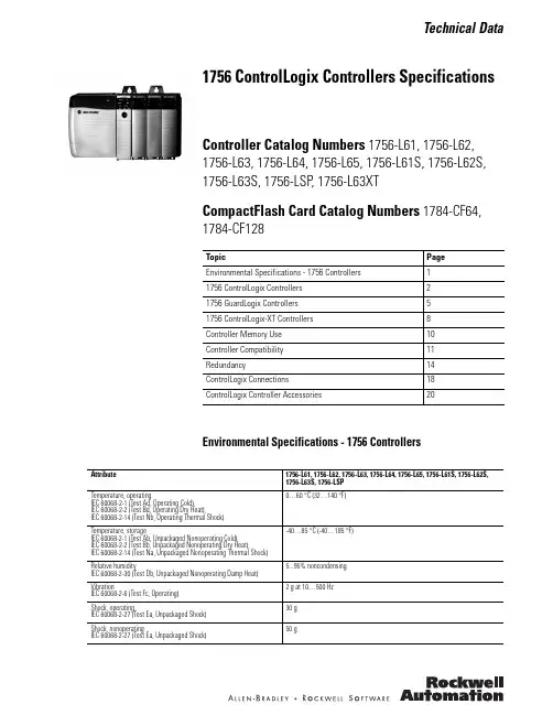
Technical Data1756 ControlLogix Controllers SpecificationsController Catalog Numbers 1756-L61, 1756-L62, 1756-L63, 1756-L64, 1756-L65, 1756-L61S, 1756-L62S, 1756-L63S, 1756-LSP , 1756-L63XTCompactFlash Card Catalog Numbers 1784-CF64, 1784-CF128Environmental Specifications - 1756 ControllersTopicPage Environmental Specifications - 1756 Controllers11756 ControlLogix Controllers 21756 GuardLogix Controllers 51756 ControlLogix-XT Controllers 8Controller Memory Use 10Controller Compatibility 11Redundancy14ControlLogix Connections 18ControlLogix Controller Accessories20Attribute1756-L61, 1756-L62, 1756-L63, 1756-L64, 1756-L65, 1756-L61S, 1756-L62S, 1756-L63S, 1756-LSP Temperature, operatingIEC 60068-2-1 (Test Ad, Operating Cold),IEC 60068-2-2 (Test Bd, Operating Dry Heat),IEC 60068-2-14 (Test Nb, Operating Thermal Shock)0…60 °C (32…140 °F)Temperature, storageIEC 60068-2-1 (Test Ab, Unpackaged Nonoperating Cold),IEC 60068-2-2 (Test Bb, Unpackaged Nonoperating Dry Heat),IEC 60068-2-14 (Test Na, Unpackaged Nonoperating Thermal Shock) -40…85 °C (-40…185 °F)Relative humidityIEC 60068-2-30 (Test Db, Unpackaged Nonoperating Damp Heat) 5...95% noncondensing VibrationIEC 60068-2-6 (Test Fc, Operating) 2 g at 10…500 Hz Shock, operatingIEC 60068-2-27 (Test Ea, Unpackaged Shock) 30 g Shock, nonoperatingIEC 60068-2-27 (Test Ea, Unpackaged Shock)50 g1756 ControlLogix Controllers Specifications1756 ControlLogix Controllers The ControlLogix controller provides a scalable controller solution that is capable of addressing a large amount of I/O points.The ControlLogix controller can be placed into any slot of a ControlLogixI/O chassis and multiple controllers can be installed in the same chassis. Multiple controllers in the same chassis communicate with each other over the backplane (just as controllers can communicate over networks) but operate independently.ControlLogix controllers can monitor and control I/O across the ControlLogix backplane, as well as over I/O links. ControlLogix controllers can communicate over EtherNet/IP, ControlNet, DeviceNet, DH+, Remote I/O, and RS-232-C (DF1/DH-485 protocol) networks and many third party process and device networks. To provide communication for a ControlLogix controller, install the appropriate communication interface module into the chassis.Feature1756-L61, 1756-L62, 1756-L63, 1756-L64, 1756-L65 Controller tasks•32 tasks•100 programs/task•Event tasks: all event triggersBuilt-in communication ports 1 port RS-232 serialCommunication options•EtherNet/IP•ControlNet•DeviceNet •Data Highway Plus•Remote I/O•SynchLink•Third party process and device networksSerial port communication•ASCII•DF1 full/half-duplex•DF1 radio modem •DH-485•Modbus via logicController connections supported, max250Network connections, per network module•100 ControlNet (1756-CN2/A)•40 ControlNet (1756-CNB)•256 EtherNet/IP; 128 TCP (1756-EN2x)•128 EtherNet/IP; 64 TCP (1756-ENBT)Controller redundancy Full supportIntegrated motion SERCOS interface Analog options:•Encoder input•LDT input•SSI inputProgramming languages•Relay ladder•Structured text •Function block •SFC1756 ControlLogix Controllers Specifications Technical Specifications - 1756 ControlLogix ControllersAttribute1756-L611756-L621756-L631756-L641756-L65User memory 2 MB 4 MB8 MB16 MB32 MBI/O memory478 KBOptional flash memory64 MB (cat. no. 1784-CF64)128 MB (cat. no. 1784-CF128)Digital I/O, max128,000Analog I/O, max4000Total I/O, max128,000Replacement battery Series A:1756-BA1,1756-BATM,1756-BATASeries B:1756-BA2Series A:1756-BA1,1756-BATM,1756-BATASeries B:1756-BA2Series A:1756-BA1,1756-BATM,1756-BATASeries B:1756-BA21756-BA2Current draw @ 5V DC1200 mACurrent draw @ 24V DC14 mAPower dissipation 3.5 WThermal dissipation11.9 BTU/hrIsolation voltage30V (continuous), Basic Insulation Type, RS-232 to systemControllers tested to withstand 707V DC for 60 sSerial cables1756-CP3 or 1747-CP3, right angle connector to controller, straight to serial port, 3 mSIL 2Use standard ControlLogix controllersSIL 3Use GuardLogix controllers (1756-L61S, 1756-L62S, 1756-L63S) and the Safety Partner (1756-LSP)Weight, approx.Series A: 0.32 kgSeries B: 0.35 kg(Series A: 0.71 lbSeries B: 0.78 lb)Series A: 0.32 kgSeries B: 0.35 kg(Series A: 0.71 lbSeries B: 0.78 lb)Series A: 0.32 kgSeries B: 0.35 kg(Series A: 0.71 lbSeries B: 0.78 lb)Series A: 0.32 kgSeries B: 0.35 kg(Series A: 0.71 lbSeries B: 0.78 lb)Series A: 0.32 kgSeries B: 0.35 kg(Series A: 0.71 lbSeries B: 0.78 lb)Slot width1Module location Chassis-based, any slotChassis1756-A4, 1756-A7, 1756-A10, 1756-A13, 1756-A17Power supply, standard1756-PA72/C, 1756-PA75/B, 1756-PB72/C, 1756-PB75/B, 1756-PC75/B, 1756-PH75/BPower supply, redundant1756-PA75R, 1756-PB75R, 1756-PSCA2Wire category 2 - on communication ports(1)North American temperature code T4AIEC temperature code T4T4T4T4T4 Enclosure type rating None (open-style)(1)Use this conductor category information for planning conductor routing as described in the system level installation manual. See the Industrial Automation Wiring and Grounding Guidelines, publication 1770-4.1.1756 ControlLogix Controllers SpecificationsCertifications - 1756 ControlLogix ControllersFor Australian Mining certification, use a 1756-BA1 battery. For guidelines, see your local distributor or sales officeCertification (1)1756-L61, 1756-L62, 1756-L63, 1756-L64, 1756-L65c-UL-usUL Listed Industrial Control Equipment, certified for US and Canada. See UL File E65584.UL Listed for Class I, Division 2 Group A,B,C,D Hazardous Locations, certified for U.S. and Canada. See UL File E194810.CSACSA Certified Process Control Equipment. See CSA File LR54689C.CSA Certified Process Control Equipment for Class I, Division 2 Group A,B,C,D Hazardous Locations. See CSA File LR69960C.ATEX European Union 94/9/EC ATEX Directive, compliant with:EN 60079-15; Potentially Explosive Atmospheres, Protection “n” (Zone 2)CEEuropean Union 2004/108/IEC EMC Directive, compliant with:•EN 61326-1; Meas./Control/Lab., Industrial Requirements •EN 61000-6-2; Industrial Immunity •EN 61000-6-4; Industrial Emissions•EN 61131-2; Programmable Controllers (Clause 8, Zone A & B)C-Tick Australian Radiocommunications Act, compliant with:AS/NZS CISPR 11; Industrial EmissionsFM FM Approved Equipment for use in Class I Division 2 Group A,B,C,D Hazardous Locations TÜVTÜV Certified for Functional Safety: up to and including SIL 2(1)When marked. See the Product Certification link at for Declarations of Conformity, Certificates, and other certification details.1756 ControlLogix Controllers Specifications1756 GuardLogix Controllers A GuardLogix controller is a ControlLogix controller that also provides safety control. The GuardLogix system is a dual controller solution — you must use a 1756-L6x S primary controller and a 1756-LSP safety partner to achieve SIL 3/CAT. 4. A major benefit of this system is that it’s still a single project, safetyand standard together. The safety partner controller is a part of the system, isautomatically configured, and requires no user setup.During development, safety and standard have the same rules, multipleprogrammers, online editing, and forcing are all allowed. Once the project istested and ready for final validation, you set the Safety Task to a SIL 3 integritylevel, which is then enforced by the GuardLogix controller. When safetymemory is locked and protected, the safety logic can't be modified and allsafety functions operate with SIL 3 integrity. On the standard side of theGuardLogix controller, all functions operate like a regular Logix controller.Thus online editing, forcing, and other activities are all allowed.With this level of integration, safety memory can be read by standard logic andexternal devices, like HMIs or other controllers, eliminating the need tocondition safety memory for use elsewhere. The result is easy system-wideintegration and the ability to display safety status on displays or marquees. UseGuard I/O modules for field device connectivity on Ethernet or DeviceNetnetworks, and for safety interlocking between GuardLogix controllers useEthernet or ControlNet networks. Multiple GuardLogix controllers can sharesafety data for zone to zone interlocking, or a single GuardLogix controller canuse remote distributed safety I/O between different cells/areas.1756 GuardLogix Controllers FeaturesIn addition to the standard features of a ControlLogix controller, theGuardLogix controller has these safety-related features.Feature1756-L61S, 1756-L62S, 1756-L63S, 1756-LSPSafety communication options Standard and safety•EtherNet/IP•ControlNet•DeviceNetNetwork connections, per network module •100 ControlNet (1756-CN2/A)•40 ControlNet (1756-CNB)•256 EtherNet/IP; 128 TCP (1756-EN2x)•128 EtherNet/IP; 64 TCP (1756-ENBT)Controller redundancy Not supported Programming languages Relay ladder1756 ControlLogix Controllers SpecificationsTechnical Specifications - 1756 GuardLogix ControllersAttribute1756-L61S1756-L62S1756-L63S1756-LSPUser memory 2 MB 4 MB8 MB—Safety memory 1 MB 1 MB 3.75 MB—I/O memory478 KB —Optional flash memory(1)64 MB (cat. no. 1784-CF64)128 MB (cat. no. 1784-CF128)—Digital I/O, max128,000—Analog I/O, max4000—Total I/O, max128,000—Replacement battery1756-BA2Current draw @ 5V DC1200 mACurrent draw @ 24V DC14 mAPower dissipation 3.5 WThermal dissipation11.9 BTU/hrIsolation voltage30V (continuous), Basic Insulation Type, RS-232 to systemControllers tested to withstand 707V DC for 60 sSerial cables1756-CP3 or 1747-CP3, right angle connector to controller, straight to serial port, 3 mSIL 2Use standard ControlLogix controllersSIL 3Use GuardLogix controllers (1756-L61S, 1756-L62S, 1756-L63S) and the Safety Partner(1756-LSP)Weight, approx.0.32 kg(0.70 lb)0.32 kg(0.70 lb)0.32 kg(0.70 lb)0.32 kg(0.70 lb)Slot width1Module location Chassis-based, any slotChassis1756-A4, 1756-A7, 1756-A10, 1756-A13, 1756-A17Power supply, standard1756-PA72/C, 1756-PA75/B, 1756-PB72/C, 1756-PB75/B, 1756-PC75/B, 1756-PH75/B Power supply, redundant1756-PA75R, 1756-PB75R, 1756-PSCA2Wire category 2 - on communication ports(2)North American temperature code T4AEnclosure type rating None (open-style)(1)The GuardLogix controller does not support user program storage or retrieval by using a CompactFlash card.(2)Use this conductor category information for planning conductor routing as described in the system level installation manual. See the Industrial Automation Wiring and Grounding Guidelines, publication 1770-4.1.1756 ControlLogix Controllers Specifications Certifications - 1756 GuardLogix ControllersCertification(1)1756-L61S, 1756-L62S, 1756-L63S, 1756-LSPUL UL Certified for Functional Safety up to and including SIL 3, see UL File E256621.(2)c-UL-us UL Listed Industrial Control Equipment, certified for US and Canada. See UL File E65584.UL Listed for Class I, Division 2 Group A,B,C,D Hazardous Locations, certified for U.S. and Canada. See UL FileE194810.CSA CSA Certified Process Control Equipment. See CSA File LR54689C.CSA Certified Process Control Equipment for Class I, Division 2 Group A,B,C,D Hazardous Locations. See CSA FileLR69960C.CE European Union 2004/108/EC EMC Directive, compliant with:•EN 61000-6-4; Industrial Emissions•EN 61326-1; Meas./Control/Lab., Industrial Requirements•EN 61000-6-2; Industrial Immunity•EN 61131-2; Programmable Controllers (Clause 8, Zone A & B)C-Tick Australian Radiocommunications Act, compliant with: AS/NZS CISPR 11; Industrial EmissionsFM FM Approved Equipment for use in Class I, Division 2 Group A, B, C, D Hazardous LocationsTÜV Functional Safety: SIL 1 to 3, according to IEC 61508; up to PL(e) according to ISO13849-1:2006; Category 1 to 4,according to EN954-1; NFPA79; when used as described in the GuardLogix Controller Systems Safety ReferenceManual, publication 1756-RM093.(1)When marked. See the Product Certification link at for Declarations of Conformity, Certificates, and other certification details.(2)When used with specified software versions.1756 ControlLogix Controllers Specifications1756 ControlLogix-XT Controllers The ControlLogix-XT controllers function in the same way as the traditional ControlLogix controllers. The ControlLogix-XT products include control and communication system components that, when used with FLEX I/O-XT products, provide a complete control system solution that can be used in environments where temperatures range from -20...70 °C (-4...158 °F). When used independently, the ControlLogix-XT system can withstand environments where the temperature ranges from -25...70 °C (-13...158 °F). Environmental Specifications - 1756-L63XT ControllerTechnical Specifications - 1756-L63XT ControllerAttribute ValueTemperature, operatingIEC 60068-2-1 (Test Ad, Operating Cold),IEC 60068-2-2 (Test Bd, Operating Dry Heat),IEC 60068-2-14 (Test Nb, Operating Thermal Shock)-25…70 °C (-13…158 °F)Temperature, storageIEC 60068-2-1 (Test Ab, Unpackaged Nonoperating Cold),IEC 60068-2-2 (Test Bb, Unpackaged Nonoperating Dry Heat),IEC 60068-2-14 (Test Na, Unpackaged Nonoperating Thermal Shock)-40…85 °C (-40…185 °F)Relative humidityIEC 60068-2-30 (Test Db, Unpackaged Nonoperating Damp Heat)5...95% noncondensingVibrationIEC 60068-2-6 (Test Fc, Operating)2 g at 10…500 HzShock, operatingIEC 60068-2-27 (Test Ea, Unpackaged Shock)30 gShock, nonoperatingIEC 60068-2-27 (Test Ea, Unpackaged Shock)50 gAttribute1756-L63XTUser memory8 MBI/O memory478 KBOptional flash memory64 MB (cat. no. 1784-CF64)128 MB (cat. no. 1784-CF128)Digital I/O, max128,000Analog I/O, max4000Total I/O, max128,000Replacement battery1756-BA2Current draw @ 5V DC1200 mACurrent draw @ 24V DC14 mAPower dissipation 3.5 WThermal dissipation11.9 BTU/hrIsolation voltage30V (continuous), Basic Insulation Type, RS-232 to systemControllers tested to withstand 707V DC for 60 s, RS232 to system1756 ControlLogix Controllers SpecificationsCertifications - 1756-L63XT ControllerSerial cables 1756-CP3 or 1747-CP3, right angle connector to controller, straight to serial port, 3 mSIL 2Use standard ControlLogix controllersSIL 3Use GuardLogix controllers (1756-L61S, 1756-L62S, 1756-L63S) and the Safety Partner (1756-LSP)Weight, approx.0.35 kg (0.78 lb)Slot width 1Module location Chassis-based, any slot Chassis1756-A5XT, 1756-A7LXT Power supply, standard 1756-PBXT Power supply, redundant NoneWire category2 - on communication ports (1)North American temperature code T4A IEC temperature code T4Enclosure type ratingNone (open-style)(1)Use this conductor category information for planning conductor routing as described in the system level installation manual. See the Industrial Automation Wiring and Grounding Guidelines, publication 1770-4.1.Attribute 1756-L63XTCertification (1)1756-L63XTc-UL-usUL Listed Industrial Control Equipment, certified for US and Canada. See UL File E65584.UL Listed for Class I, Division 2 Group A,B,C,D Hazardous Locations, certified for U.S. and Canada. See UL File E194810.ATEX European Union 94/9/EC ATEX Directive, compliant with:EN 60079-15; Potentially Explosive Atmospheres, Protection “n” (Zone 2)CEEuropean Union 2004/108/EC EMC Directive, compliant with:•EN 61000-6-4; Industrial Emissions•EN 61326-1; Meas./Control/Lab., Industrial Requirements •EN 61000-6-2; Industrial Immunity•EN 61131-2; Programmable Controllers (Clause 8, Zone A & B)C-TickAustralian Radiocommunications Act, compliant with: AS/NZS CISPR 11; Industrial Emissions(1)When marked. See the Product Certification link at for Declarations of Conformity, Certificates, and other certification details.1756 ControlLogix Controllers SpecificationsController Memory UseThe following equations provide an estimate of the memory needed for a controller. These numbers are rough estimates.For redundant controller systems, double the memory estimate you calculate. For example, if you estimate you need 2 MB of memory, select a controller with 4 MB of memory.Reserve 20...30% of the controller memory to accommodate growth.Controller tasks _____ * 4000 = _____ bytes (minimum 1 task) Digital I/O points _____ * 400 = _____ bytes Analog I/O points _____ * 2600 = _____ bytes DeviceNet modules (1)_____ * 7400 = _____ bytes Other communication modules (2)_____ * 2000 = _____ bytes Motion axis_____ * 8000 = _____ bytesFactoryTalk alarm instruction _____ * 1000 = _____ bytes (per alarm) FactoryTalk subscriber_____ * 10000=_____ bytes(1)The first DeviceNet module is 7400 bytes. Additional DeviceNet modules are 5800 bytes each.(2)Count all the communication modules in the system, not just those in the local chassis. This includes device connection modules, adapter modules, and ports on PanelView terminals.Controller Compatibility Control Distributed I/O ModulesThe controller can control these distributed I/O modules via the I/OConfiguration tree in RSLogix 5000 programming software.I/O Modules EtherNet/IP ControlNet DeviceNet Remote I/OChassis-based I/O1746 SLC I/O No No No Yes1756 ControlLogix I/O Yes Yes No No1769 Compact I/O No No Yes No1771 Universal I/O No Yes No YesIn-Cabinet I/O1734 POINT I/O Yes Yes Yes No1734D POINTBlock I/O No No Yes No1790, 1790D, 1790P CompactBlock LDX I/O No No Yes No1791D, 1791P, 1791R CompactBlock I/O No No Yes No1794 FLEX I/O Yes Yes Yes Yes1797 FLEX Ex I/O No Yes No NoOn-Machine I/O1732 ArmorBlock I/O Yes No Yes No1738 ArmorPoint I/O Yes Yes Yes No1792D ArmorBlock MaXum I/O No No Yes No1799 Embedded I/O No No Yes NoControl Safety I/O ModulesThe GuardLogix controller can control these safety I/O modules in a safetysystem.I/O Modules EtherNet/IP ControlNet DeviceNetIn-Cabinet I/O1791DS CompactBlock Guard I/O No No Yes1791ES CompactBlock Guard I/O Yes No No1734 Point Guard I/O Yes No NoOn-Machine I/O1732DS ArmorBlock Guard I/O No No YesCommunicate with Display DevicesThe controller can communicate with these display devices.Communicate with Other ControllersThe controller can communicate with these programmable controllers.Display Devices EtherNet/IP ControlNet DeviceNet DH+ Remote I/O RS-232 (DF1) DH-485Industrial Computers Rockwell Automation industrial computers (all)(1)Yes Yes Yes Yes Yes Yes YesGraphic TerminalsPanelView Plus and PanelView CE terminalsYes Yes Yes Yes Yes Yes Yes PanelView Standard terminals Yes Yes Yes Yes Yes Yes Yes PanelView “e” terminals NoYesNoYesYesNoNoMessage Displays InView message displaysYes Yes Yes Yes Yes Yes Yes(1)Includes: Rockwell Automation integrated display rotating media (HDD) and solid state (SSD) computers, Rockwell Automation non-display computers, and Rockwell Automation integrated display computers with keypad.ControllerEtherNet/IP ControlNet DeviceNet DH+ RS-232 (DF1) DH-485(1)1756 ControlLogix, 1756 GuardLogixYes Yes Yes Yes Yes Yes 1768, 1769 CompactLogix Yes Yes Yes No Yes Yes 1789 SoftLogix5800 Yes Yes Yes No Yes No 1794 FlexLogixYes Yes Yes No Yes Yes PowerFlex with DriveLogix Yes Yes Yes No Yes Yes 1785 PLC-5 Yes (2) (3)Yes Yes (4)Yes Yes — 1747 SLC Yes (5)Yes Yes (4)Yes Yes Yes 1761 MicroLogix Yes No Yes (4)No Yes Yes 1762 MicroLogix Yes No Yes (4)No Yes Yes 1763 MicroLogix Yes No Yes (4)No Yes Yes 1764 MicroLogix Yes No Yes (4)No Yes Yes 1772 PLC-2 — — — Yes Yes — 1775 PLC-3 — — — Yes Yes — 5250 PLC-5/250——NoYesYes—(1)The 1756-DH485 module supports full DH-485 functionality.(2)The Ethernet PLC-5 controller must be series C, firmware revision N.1 or later; series D, firmware revision E.1 or later; or series E, firmware revision D.1 or later.(3)The 1785-ENET Ethernet communication interface module must be series A, firmware revision D or later.(4)The PLC-5, SLC, and MicroLogix processors appear as I/O points to the Logix controller. Use the appropriate DeviceNet interface for the controller.(5)Use a 1747-L55x controller with OS501 or greater.Communicate with Other Communication DevicesThe controller can communicate with these communication devices. Communication Device EtherNet/IP ControlNet DeviceNet DH+Linking device (ControlLogix controllers only) 1788-EN2DN 1788-CN2DN1788-CN2FF1788-EN2DN1788-CN2DN—PCMCIA card — 1784-PCC 1784-PCD 1784-PCMKPCI card — 1784-PCIC1784-PCICS 1784-PCID1784-PCIDS1784-CPCIDS—Drives SCANport module — 1203-FM11203-FB1(1)— —Communication module — 1203-CN(2)1770-KFC151770-KFCD151747-KFC15 1770-KFD1770-KFG—Communication card — 1784-PKTCS1784-KTCS1784-KTCX15 1784-PKTX1784-PKTXD—USB communication device — 1784-U2CN 1784-U2DN 1784-U2DHP(1)Use a CIP generic MSG instruction to communicate with the 1203-FM1 SCANport module on a DIN rail that is remote to the controller. The remote DIN rail also requires a 1794-ACN15 or 1794ACNR15 ControlNet adapter module.(2)Use the generic module configuration to configure the 1203-CN1 module and a CIP generic MSG instruction to communicate with the module.Redundancy The ControlLogix controller supports controller redundancy. In a redundantcontroller system, you need these components:•Two 1756 chassis each with the same:–number of slots.–modules in the same slots.–redundancy firmware revisions in each module.–Two additional ControlNet nodes outside the redundant chassis pair.You need one of the following redundancy modules:•One 1756-RM module per chassis, which supports:–two 1756-L61, 1756-L62, 1761-L63 controllers or one 1756-L64controller.–maximum of seven communication modules, which can be1756-CN2 series B, 1756-CN2R series B, and 1756-EN2T modules.–one 1756-RMC x cable.•One 1757-SRM module per chassis, which supports:–one 1756-L61, 1756-L62, 1756-L63, 1756-L64 controller–maximum of seven communication modules, which can be1756-CNB series D or E, 1756-CNBR series D or E, 1756-ENBT,and 1756-EWEB modules–one 1757-SRC x cableTechnical Specifications - 1756, 1757 Redundancy ModulesAttribute1756-RM 1757-SRMVoltage, max — 30V AC/DCCurrent, max — 100 mACurrent draw @ 1.2V DC 4 mA —Current draw @ 3.3V DC — 750 mACurrent draw @ 5V DC 1200 mA 1000 mACurrent draw @ 24V DC 120 mA 90 mAPower dissipation 9.0 W 9.6 WThermal dissipation 31 BTU/hr 38.49 BTU/hrConnector cables 1756-RMC1, 1 m (3.28 ft)1756-RMC3, 3 m (9.84 ft)1756-RMC10, 10 m (32.81 ft) 1757-SRC1, 1 m (3.28 ft)1757-SRC3, 3 m (9.84 ft)1757-SRC10, 10 m (32.81 ft) 1757-SRC50, 50 m (164.04 ft) 1757-SRC100, 100 m (328.08 ft)Slot width 1 slot 2 slotModule location Chassis-based, any slot Chassis-based, any slot. Recommended defaults:slots 5-6 in 10-slot and 17-slot chassis, slots 4-5 in7-slot and 13-slot chassisChassis 1756-A4, 1756-A7, 1756-A10, 1756-A13, 1756-A17Certifications - 1756, 1757 Redundancy ModulesPower supply, standard 1756-PA72/C, 1756-PA75/B, 1756-PB72/C, 1756-PB75/B, 1756-PC75/B, 1756-PH75/B Power supply, redundant 1756-PA75R, 1756-PB75R, 1756-PSCA2 Wire size—Relay Terminals:0.3... 2.1 mm 2 (22...14 AWG) solid or stranded shielded copper wire rated at 75 °C (167 °F) or greater 1.2 mm (3/64 in.) insulation max Wire category — 3 - on relay terminals (1)Wire type— Copper North American temperature code T4 T4A IEC temperature code—T4(1)Use this conductor category information for planning conductor routing as described in the system level installation manual. See the Industrial Automation Wiring and Grounding Guidelines, publication 1770-4.1.Attribute1756-RM 1757-SRMCertification (1)1756-RM, 1757-SRMc-UL-usUL Listed Industrial Control Equipment, certified for US and Canada. See UL File E65584.UL Listed for Class I, Division 2 Group A,B,C,D Hazardous Locations, certified for U.S. and Canada. See UL File E194810.CSACSA Certified Process Control Equipment. See CSA File LR54689C.CSA Certified Process Control Equipment for Class I, Division 2 Group A,B,C,D Hazardous Locations. See CSA File LR69960C.ATEX European Union 94/9/EC ATEX Directive, compliant with:EN 60079-15; Potentially Explosive Atmospheres, Protection “n” (Zone 2)CEEuropean Union 2004/108/IEC EMC Directive, compliant with:•EN 61326-1; Meas./Control/Lab., Industrial Requirements •EN 61000-6-2; Industrial Immunity •EN 61000-6-4; Industrial Emissions•EN 61131-2; Programmable Controllers (Clause 8, Zone A & B)C-Tick Australian Radiocommunications Act, compliant with:AS/NZS CISPR 11; Industrial EmissionsFM FM Approved Equipment for use in Class I Division 2 Group A,B,C,D Hazardous Locations TÜVTÜV Certified for Functional Safety: up to and including SIL 2(1)When marked. See the Product Certification link at for Declarations of Conformity, Certificates, and other certification details.Environmental Specifications - 1756-RMXT Redundancy ModuleTechnical Specifications - 1756-RMXT Redundancy ModuleAttribute1756-RMXTTemperature, operatingIEC 60068-2-1 (Test Ad, Operating Cold),IEC 60068-2-2 (Test Bd, Operating Dry Heat),IEC 60068-2-14 (Test Nb, Operating Thermal Shock)-25…70 °C (-13…158 °F)Temperature, storageIEC 60068-2-1 (Test Ab, Unpackaged Nonoperating Cold),IEC 60068-2-2 (Test Bb, Unpackaged Nonoperating Dry Heat),IEC 60068-2-14 (Test Na, Unpackaged Nonoperating Thermal Shock) -40…85 °C (-40…185 °F)Relative humidityIEC 60068-2-30 (Test Db, Unpackaged Nonoperating Damp Heat) 5...95% noncondensing VibrationIEC 60068-2-6 (Test Fc, Operating) 2 g at 10…500 Hz Shock, operatingIEC 60068-2-27 (Test Ea, Unpackaged Shock) 30 g Shock, nonoperatingIEC 60068-2-27 (Test Ea, Unpackaged Shock)50 gAttribute1756-RMXT Current draw @ 1.2V DC 4 mA Current draw @ 5.1V DC 1.2 A Current draw @ 24V DC 120 mA Power dissipation 9.0 W Thermal dissipation 31 BTU/hrConnector cables1756-RMC1, 1 m (3.28 ft)1756-RMC3, 3 m (9.84 ft)1756-RMC10, 10 m (32.81 ft) Slot width 1 slotModule location Chassis-based, any slot Chassis1756-A5XT, 1756-A7LXT Power supply, standard 1756-PBXT Power supply, redundant None North American temperature codeT4Certifications - 1756-RMXT Redundancy ModuleCertification(1)1756-RMXTc-UL-us UL Listed Industrial Control Equipment, certified for US and Canada. See UL File E65584.UL Listed for Class I, Division 2 Group A,B,C,D Hazardous Locations, certified for U.S. and Canada. See UL FileE194810.CSA CSA Certified Process Control Equipment. See CSA File LR54689C.CSA Certified Process Control Equipment for Class I, Division 2 Group A,B,C,D Hazardous Locations. See CSA FileLR69960C.CE European Union 2004/108/IEC EMC Directive, compliant with:•EN 61326-1; Meas./Control/Lab., Industrial Requirements•EN 61000-6-2; Industrial Immunity•EN 61000-6-4; Industrial Emissions•EN 61131-2; Programmable Controllers (Clause 8, Zone A & B)C-Tick Australian Radiocommunications Act, compliant with:AS/NZS CISPR 11; Industrial EmissionsFM FM Approved Equipment for use in Class I Division 2 Group A,B,C,D Hazardous Locations(1)When marked. See the Product Certification link at for Declarations of Conformity, Certificates, and other certification details.。