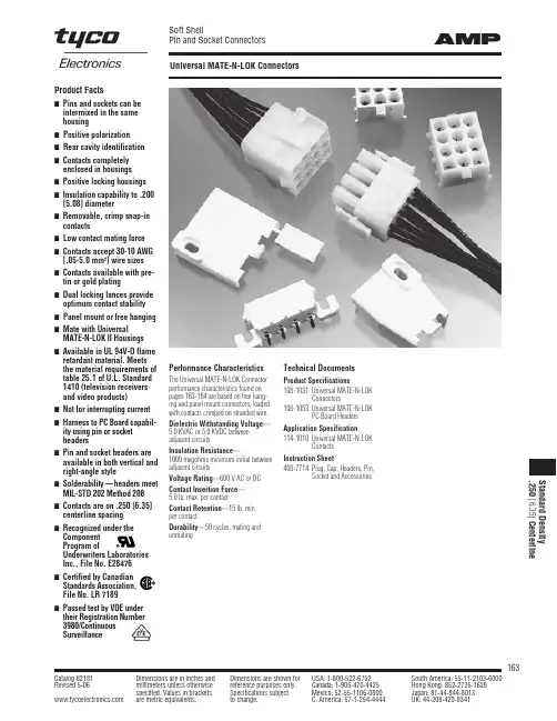
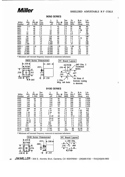
9109中文资料
- 格式:pdf
- 大小:128.29 KB
- 文档页数:1

AOD609中文资料Symbol DeviceTyp Max Units n-ch 17.425°C/W n-ch 5060°C/W R θJC n-ch 4 5.5°C/W p-ch 16.725°C/W p-ch 5060°C/W R θJCp-ch3.55°C/WMaximum Junction-to-Lead CSteady-State ParameterMaximum Junction-to-Ambient A,Dt ≤ 10s R θJA Maximum Junction-to-Ambient A,DR θJA Maximum Junction-to-AmbientA,DSteady-State Steady-State Thermal Characteristics: n-channel and p-channel Maximum Junction-to-Lead C Steady-State Maximum Junction-to-Ambient A,Dt ≤ 10s AOD609SymbolMin TypMaxUnits BV DSS 40V 1T J =55°C5I GSS ±100nAV GS(th) 1.7 2.5 3 VI D(ON)30A2430T J =125°C37463140g FS 25S V SD 0.761V I S2A C iss 516650pF C oss 82pF C rss 43pF R g4.6 6.9?Q g (10V)8.310.8nC Q gs 2.3nC Q gd 1.6nC t D(on) 6.4ns t r 3.6ns t D(off)16.2ns t f 6.6ns t rr 1824ns Q rr10nC THIS PRODUCT HAS BEEN DESIGNED AND QUALIFIED FOR THE CONSUMER MARKET. APPLICATIONS OR USES AS CRITICAL COMPONENTS IN LIFE SUPPORT DEVICES OR SYSTEMS ARE NOT AUTHORIZED. AOS DOES NOT ASSUME ANY LIABILITY ARISING OUT OF SUCH APPLICATIONS OR USES OF ITS PRODUCTS. AOS RESERVES THE RIGHT TO IMPROVE PRODUCT DESIGN,FUNCTIONS AND RELIABILITY WITHOUT NOTICE.Input Capacitance V GS =0V, V DS =0V, f=1MHzSWITCHING PARAMETERS Reverse Transfer Capacitance Gate resistanceI S =1A,V GS =0V V GS =10V, I D =12ADiode Forward Voltage V GS =10V, V DS =20V, R L =1.4?, R GEN =3?Gate Source Charge Gate Drain Charge Turn-On DelayTime Turn-On Rise Time Total Gate Charge V GS =10V, V DS =20V,I D =12AR DS(ON)Static Drain-Source On-ResistanceForward TransconductanceV GS =4.5V, I D =8AV DS =5V, I D =12Am ?Gate Threshold Voltage V DS =V GS I D =250μA On state drain currentV GS =10V, V DS =5V μAGate-Body leakage current V DS =0V, V GS = ±20V N Channel Electrical Characteristics (T J =25°C unless otherwise noted)ParameterConditions STATIC PARAMETERS Drain-Source Breakdown Voltage I D =250μA, V GS =0V I DSS Zero Gate Voltage Drain Current V DS =40V, V GS =0VMaximum Body-Diode Continuous CurrentDYNAMIC PARAMETERS Body Diode Reverse Recovery ChargeI F =12A, dI/dt=100A/μsTurn-Off DelayTime Turn-Off Fall TimeBody Diode Reverse Recovery Time I F =12A, dI/dt=100A/μs V GS =0V, V DS =20V, f=1MHz Output Capacitance A: The value of R θJA is meas ured with the device in a still air environment with T A =25°C. The power dissipation P DSM and current rating I DSM are based on T J(MAX)=150°C, using the steady state junction-to-ambient thermal resistance.B. The power dissipation P D is based on T J(MA X)=175°C, using junction-to-case thermal resistance, and is more useful in setting the upper dissipation limit for cases where additional heatsinking is used.C: Repetitive rating, pulse width limited by junction temperature T J(MAX)=175°C.D. The R θJA is the sum of the thermal impedence from junction to case R θJC and case to ambient.E. The static characteristics in Figures 1 to 6 are obtainedusing <300 μs pulses, duty cycle 0.5% max.F. These curves are based on the junction-to-case thermal impedence which is measured with the device mounted to a large heatsink, assuming a maximum junction temperature of T J(MAX)=175°C. The SOA curve provides a single pulse rating.G. These tests are performed with the device mounted on 1 in 2FR-4 board with 2oz. Copper, in a still air environment with T A =25°C. H. The maximum current rating is limited by bond-wires. Rev0: Nov 2007SymbolMin TypMaxUnits BV DSS -40V -1T J =55°C-5I GSS ±100nA V GS(th)-1.7-2 -3 VI D(ON)-30A3645T J =125°C52655166g FS 22S V SD -0.76-1V I S-2A C iss 9001125pF C oss 97pF C rss 68pF R g14?Q g (-10V)16.221nC Q g (-4.5V)7.29.4nC Q gs 3.8nC Q gd 3.5nC t D(on) 6.2 ns t r 8.4ns t D(off)44.8ns t f 41.2ns t rr 2127ns Q rr14nC THIS PRODUCT HAS BEEN DESIGNED AND QUALIFIED FOR THE CONSUMER MARKET. APPLICATIONS OR USES AS CRITICAL COMPONENTS IN LIFE SUPPORT DEVICES OR SYSTEMS ARE NOT AUTHORIZED. AOS DOES NOT ASSUME ANY LIABILITY ARISING OUT OF SUCH APPLICATIONS OR USES OF ITS PRODUCTS. AOS RESERVES THE RIGHT TO IMPROVE PRODUCT DESIGN,FUNCTIONS AND RELIABILITY WITHOUT NOTICE.P-Channel Electrical Characteristics (T J =25°C unless otherwise noted)ParameterConditionsSTATIC PARAMETERS Drain-Source Breakdown Voltage I D = -250μA, V GS =0V I DSS Zero Gate Voltage Drain Current V DS = -40V, V GS =0VμA Gate-Body leakage current V DS =0V, V GS = ±20V Gate Threshold Voltage V DS =V GS I D = -250μA On state drain currentV GS = -10V, V DS = -5V m ?V DS = -5V, I D = -12AR DS(ON)Static Drain-Source On-ResistanceForward TransconductanceV GS = -10V, I D = -12AV GS = -4.5V, I D = -8ADiode Forward Voltage I S = -1A,V GS =0V Maximum Body-Diode Continuous CurrentReverse Transfer Capacitance DYNAMIC PARAMETERS Input Capacitance V GS =0V, V DS = -20V, f=1MHz Gate resistance Output Capacitance V GS =0V, V DS =0V, f=1MHzSWITCHING PARAMETERS Total Gate Charge V GS = -10V, V DS = -20V, I D = -12AV GS = -10V, V DS = -20V, R L =1.4?, R GEN =3?Turn-On Rise Time Turn-Off DelayTime Turn-Off Fall TimeGate Source Charge Gate Drain Charge Turn-On DelayTime Total Gate Charge Body Diode Reverse Recovery TimeI F = -12A, dI/dt=100A/μsBody Diode Reverse Recovery Charge I F = -12A, dI/dt=100A/μsA: The value of R θJA is measured with the device in a still air environment with T A =25°C. The power dissipation P D SM and current rating I DSM are based on T J(MAX)=150°C, using t ≤ 10s junction-to-ambient thermal resistance.B. The power dissipation P D is based on T J(MAX)=175°C, using junction-to-case thermal resistance, and is more useful in setting the upper dissipation limit for cases where additional heatsinking is used. C: Repetitive rating, pulse width limited by junction temperature T J(MAX)=175°C.D. The R θJA is the sum of the thermal impedence from junction to case R θJC and case to ambient.E. The static characteristics in Figures 1 to 6 are obtained using <300 μs pulses, duty cycle 0.5% max.F. These curves are based on the junction-to-case thermal impedence which is measured with the device mounted to a large heatsink, assuming a maximum junction temperature of T J(MAX)=175°C. The SOA curve provides a single pulse rating.G. These tests are performed with the device mounted on 1 in 2FR-4 board with 2oz. Copper, in a still air environment with T A =25°C. H. The maximum current rating is limited by bond-wires. Rev0:Nov 2007。


This document was generated on 08/07/2012PLEASE CHECK FOR LATEST PART INFORMATIONPart Number:91716-1012Status:ActiveOverview:RAST 2.5 Connector SystemDescription:2.50mm Appli-Mate RAST 2.5 IDT Housing, Direct/Indirect, Female, 5 Circuits,Removed Position Key BDocuments:3D ModelApplication Specification AS-99033-0008 (PDF)Drawing (PDF)Packaging Specification PK-90871-001 (PDF)Product Specification PS-99020-0040 (PDF)RoHS Certificate of Compliance (PDF)Agency CertificationCSA LR19980ULE29179GeneralProduct Family IDT and Solder Connectors Series91716Crimp Quality Equipment YesOverviewRAST 2.5 Connector System Product Name RAST 2.5UPC 822348490202Use WithRAST standard interface PhysicalCircuits (Loaded)4Circuits (maximum)4Color - ResinNatural (White)Durability (mating cycles max)10Flammability 94V-0GenderFemale Glow-Wire Compliant No Lock to Mating Part NoneMaterial - MetalPhosphor Bronze Material - Plating MatingTin Material - Plating Termination Tin Material - Resin Nylon Net Weight1.248/g Number of Rows 1Packaging Type Tray Panel MountNoPitch - Mating Interface2.50mm Pitch - Termination Interface 2.50mm Plating min - Mating1.016µm Plating min - Termination 1.016µm Polarized to Mating Part No StackableNoTemperature Range - Operating -20°C to +85°C Termination Interface: Style IDT or Pierce Wire Size AWG22, 24ElectricalCurrent - Maximum per Contact 2A, 4A Voltage - Maximum32V ACMaterial InfoSeriesimage - Reference onlyEU RoHSChina RoHSELV and RoHS Compliant REACH SVHCContains SVHC: No Low-Halogen Status Not ReviewedNeed more information on product environmental compliance?Email productcompliance@For a multiple part number RoHS Certificate of Compliance, click herePlease visit the Contact Us section for any non-product compliance questions.Search Parts in this Series 91716SeriesMates WithAppli-Mate RAST 2.5 Header 90861 , 90860Application Tooling | FAQTooling specifications and manuals are found by selecting the products below.Crimp Height Specifications are then contained in the Application Tooling Specification document.GlobalDescription Product #RAST 2.5 Semi-AutomaticTerminator Machine0623006200Reference - Drawing NumbersApplication Specification AS-99033-0008Packaging Specification PK-90871-001Product Specification PS-99020-0040Sales Drawing SD-91716-001This document was generated on 08/07/2012PLEASE CHECK FOR LATEST PART INFORMATION分销商库存信息: MOLEX 0917161012。