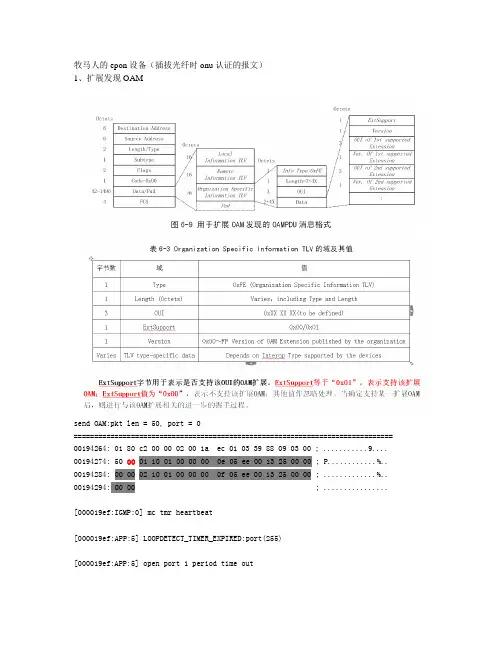
ASAM_XCP_Part3-Transport-Layer-Specification_XCPonSxI_V1-1-0
- 格式:pdf
- 大小:102.30 KB
- 文档页数:26
XCPVersion 1.1Part 3- Transport Layer SpecificationXCP on SxIPart 3 – XCP on SxI – Transport Layer SpecificationA ssociation for S tandardisation ofA utomation and M easuring SystemsDated:31-03-2008©ASAM e. V.Part 3- Transport Layer Specification XCP on SxI2 XCP Version 1.1 ReleaseStatus of DocumentDate: 31-03-2008Authors:Roel Schuermans, Vector Informatik GmbH Andreas Zeiser, Vector Informatik GmbH Oliver Kitt, Vector Informatik GmbHHans-Georg Kunz, VDO Automotive AG Hendirk Amsbeck, dSPACE GmbH Bastian Kellers, dSPACE GmbH Boris Ruoff, ETAS GmbHReiner Motz, Robert Bosch GmbH Dirk Forwick, Robert Bosch GmbH Version: Version 1.1 Doc-ID:Status: Release TypePart 3- Transport Layer Specification XCP on SxIXCP Version 1.1 Release3Revision HistoryThis revision history shows only major modifications between release versions.Date Author Filename Comments2008-03-31 R.SchuermansReleased documentPart 3- Transport Layer Specification XCP on SxI4 XCP Version 1.1 ReleasePart 3- Transport Layer Specification XCP on SxIXCP Version 1.1 Release5Table of contents0 Introduction70.1 The X CP Protocol Family 7 0.2 Documentation Overview 8 0.3 Definitions and Abbreviations9 0.4 Mapping between XCP Data Types and ASAM Data Types101 The X CP Transport Layer for SxI (SPI and SCI)111.1 Addressing11 1.2 Communication Model 12 1.3 Header and Tail 13 1.3.1 Header13 1.3.1.1 Length 13 1.3.1.2 Counter 13 1.3.2 Tail14 1.3.2.1 Fill Bytes 14 1.3.2.2 Checksum14 1.4 The Limits of performance 15 1.5 Communication Modes16 1.5.1 Asynchronous communication mode (SCI)16 1.5.1.1 Asynchronous communication mode with framing 16 1.5.2 Synchronous communication mode (SPI)17 1.5.2.1 Full duplex mode 17 1.5.2.2 Master/Slave mode182 Specific commands for X CP on SxI 193 Specific events for X CP on SxI203.1 Dummy packet214 Interface to ASAM MCD 2MC description file224.1 ASAM MCD 2MC AML for X CP on SxI 22 4.2 IF_DATA example for X CP on SxI 24Part 3- Transport Layer Specification XCP on SxI6 XCP Version 1.1 ReleaseTable of diagrams:Diagram 1 : Header and Tail for X CP on SxI 13 Diagram 2 : Header Types for X CP on SxI 13 Diagram 3 : Fill bytes in Tail for X CP on SxI 14 Diagram 4 : Checksum in Tail for X CP on SxI 14 Diagram 5 : framing for XCP on SCI 16Part 3- Transport Layer Specification XCP on SxIXCP Version 1.1 Release70 I NTRODUCTION0.1 T HE X CP P ROTOCOL F AMILYThis document is based on experiences with the C AN C alibration P rotocol (CCP) version 2.1 as described in feedback from the companies Accurate Technologies Inc., Compact Dynamics GmbH, DaimlerChrysler AG, dSPACE GmbH, ETAS GmbH, Kleinknecht Automotive GmbH, Robert Bosch GmbH, Siemens VDO Automotive AG and Vector Informatik GmbH.The X CP Specification documents describe an improved and generalized version of CCP.The generalized protocol definition serves as standard for a protocol family and is called “X CP” (Universal Measurement and C alibration P rotocol).The “X ” generalizes the “various” transportation layers that are used by the members of the protocol family e.g “X CP on CAN”, “X CP on TCP/IP”, “X CP on UDP/IP”, “X CP on USB” and so on.Part 3- Transport Layer Specification XCP on SxI8 XCP Version 1.1 Release0.2 D OCUMENTATION O VERVIEWThe X CP specification consists of 5 parts. Each part is a separate document and has the following contents:Part 1 “Overview” gives an overview over the X CP protocol family, the X CP features and the fundamental protocol definitions.Part 2 “Protocol Layer Specification” defines the generic protocol, which is independent from the transportation layer used.Part 3 “Transport Layer Specification” defines the way how the X CP protocol is transported by a particular transportation layer like CAN, TCP/IP and UDP/IP.This document describes the way how the X CP protocol is transported on SxI interfaces.Part 4 “Interface Specification” defines the interfaces from an X CP master to an ASAM MCD 2MC description file and for calculating Seed & Key algorithms and checksums.Part 5 “Example Communication Sequences” gives example sequences for typical actions performed with X CP.Everything not explicitly mentioned in this document, should be considered as implementation specific.Part 3- Transport Layer Specification XCP on SxIXCP Version 1.1 Release90.3 D EFINITIONS AND A BBREVIATIONSThe following table gives an overview about the most commonly used definitions and abbreviations throughout this document.Abbreviation Description A2L File Extension for an A SAM 2MC L anguage File AML A SAM 2 M eta L anguageASAM A ssociation for S tandardization of A utomation and M easuring Systems BYP BYP assing CAL CAL ibrationCAN C ontroller A rea N etwork CCP C an C alibration P rotocol CMD C o M man D CS C heck S umCTO C ommand T ransfer O bject CTR C oun T e RDAQ D ata A c Q uisition, D ata A c Q uisition Packet DTO D ata T ransfer O bject ECU E lectronic C ontrol U nit ERR ERR or Packet EV EV ent Packet LEN LEN gthMCD M easurement C alibration and D iagnostics MTA M emory T ransfer A ddress ODT O bject D escriptor T able PAG PAG ingPGM P ro G ra M ming PID P acket ID entifierRES command RES ponse packet SERV SERV ice request packet SPI S erial P eripheral I nterface STD ST an D ardSTIM Data STIM ulation packetTCP/IP T ransfer C ontrol P rotocol / I nternet P rotocol TST ime StampUDP/IP U nified D ata P rotocol / I nternet P rotocol USB U niversal S erial B usXCP Universal C alibration P rotocolTable 1: Definitions and AbbreviationsPart 3- Transport Layer Specification XCP on SxI10 XCP Version 1.1 Release0.4 M APPING BETWEEN XCP D ATA T YPES AND ASAM D ATA T YPESThe following table defines the mapping between data types used in this specification and ASAM data types defined by the Project Data Harmonization Version 2.0 (ref. ).XCP Data Type ASAM Data Type BYTE A_UINT8 WORD A_UINT16 DWORD A_UINT32 DLONG A_UINT641 T HE X CP T RANSPORT L AYER FOR S X I(SPI AND SCI) 1.1 A DDRESSINGIn general SPI and SCI (SxI) are no bus interfaces, they are used as a point to pointconnection. Therefore an addressing feature is not part of the transport layer.1.2 C OMMUNICATION M ODELX CP on SxI makes use of the standard communication model.The block transfer communication is optional.The interleaved communication model is optional.1.3 H EADER AND T AILDiagram 1 : Header and Tail for X CP on SxI1.3.1H EADERThe X CP packet header for SxI consists of a Control Field containing a LEN gth (LEN) and an optional C oun T e R (CTR). 1.3.1.1 L ENGTHLEN is the number of bytes in the original X CP Packet. LEN can be BYTE or WORD (Intel format). 1.3.1.2 C OUNTERThe CTR value in the X CP Header allows to detect missing Packets.The master has to generate a CTR value when sending a CMD or STIM message. The CTR value must be incremented for each new packet sent from master to the slave.The slave has to generate a (second, independent) CTR value when sending RES, ERR_EV, SRM or DAQ messages. The CTR value must be incremented for each new packet sent from slave to the master.If available, CTR always has the same size as LEN.Diagram 2 : Header Types for X CP on SxI1.3.2T AIL1.3.2.1 F ILL B YTESDepending on the alignment (when using the SPI in WORD or DWORD mode) and the minimum packet size (when Master/Slave SPI mode is used), LEN_FILL (= MAX_CTO(DTO)–LEN) optional fill bytes can be added at the end of the X CP Message.Diagram 3 : Fill bytes in Tail for X CP on SxI1.3.2.2 C HECKSUMThe X CP Tail may contain an optional BYTE or WORD size checksum.For a BYTE checksum the calculation must be done byte-wise, for a WORD checksum the calculation must be done word-wise. The checksum is calculated by adding the bytes of the X CP Header, the bytes of the X CP Packet and the Fill bytes of the X CP Tail into a BYTE or WORD checksum, ignoring overflows.Diagram 4 : Checksum in Tail for X CP on SxI1.4 T HE L IMITS OF PERFORMANCEThere are no additional restrictions of MAX_CTO and MAX_DTO for X CP on SxI.Name Type Representation Range of valueMAX_CTO Parameter BYTE 0x08 – 0xFFMAX_DTO Parameter WORD 0x0008 – 0xFFFF1.5 C OMMUNICATION M ODES1.5.1 A SYNCHRONOUS COMMUNICATION MODE (SCI)In asynchronous (SCI) full duplex mode each direction is fully independent of the other and there are no restrictions regarding the protocol.1.5.1.1 A SYNCHRONOUS COMMUNICATION MODE WITH FRAMINGDiagram 5 : framing for XCP on SCIFor improving frame detection capabilities, a framing mechanism can be used.The framing protocol defines two special characters: SYNC and ESC. If framing is used, every XCP on SCI Message is preceded by a SYNC character. If Inside the XCP on SCI Message a data byte occurs that is the same as SYNC, it is replaced by the two-byte sequence ESC+ESC_SYNC. If inside the XCP on SCI Message a data byte occurs that is the same as ESC, it is replaced by the two-byte sequence ESC+ESC_ESC.With the FRAMING block in the ASAM MCD 2MC description file the slave can inform the master that it has to use the framing mechanism.SYNC and ESC are configurable, ESC_SYNC = 0x01, ESC_ESC = 0x00.1.5.2 S YNCHRONOUS COMMUNICATION MODE (SPI)1.5.2.1 F ULL DUPLEX MODEIn synchronous (SPI) full duplex mode each direction has its own clock line.Both directions are fully independent of each other and there are no restrictions regarding the protocol.This mode is available for BYTE, WORD and DWORD SPI interfaces.When using a WORD or DWORD SPI interface, alignment requirements must be met.In this case the Identification_Field_Type for DAQ packets must be 0x01 or 0x03. Also the timestamp size must be 2 or 4 byte.For X CP messages with odd length, a fill byte must be added in the X CP Tail.Example:LEN CTR ODT DAQ Timestamp Data9 0 X X 3 1 T_l T_h D[0] D[1] D[2] D[3] D[4] 0DAQ message : WORD LEN, WORD CTR, WORD SPI, no CS, 1 fill byte1.5.2.2 M ASTER/S LAVE MODEIn synchronous (SPI) master/slave mode, one clock line is used for both directions.The device which supplies the clock is called the SPI master.In this case the SPI slave can only send a message, if the SPI master sends a message in parallel, because the clock is required from SPI master. The SPI slave must ensure, that the message to be transmitted starts synchronously to the message to be received.For DAQ purposes the X CP slave should be the SPI master to ensure that it is able to transmit a DAQ packets with low latency.During configuration time, when no DAQ is running, the X CP slave must transmit dummy packets in order to enable the X CP master to send command packets for configuration. This needs to be done frequently.The dummy packet is defined as an event packet with the event code EV_TRANSPORT. All other bytes of this event packet must be zero to be compatible with future extensions.Example:LEN CTR PID EV Fill bytes2 0 X X 0xFD 0xFF 0 0 0 0 0 0Dummy message with WORD LEN and CTR:The minimum length for all packets sent by the X CP slave must be at least MAX_CTO.This is to ensure that all kind of command packets could be sent by the X CP master.This mode is available for BYTE, WORD and DWORD SPI interfaces.When using a WORD or DWORD SPI interface, the same alignment requirements as for Full Duplex Mode must be met2 S PECIFIC COMMANDS FOR X CP ON S X IThere are no specific commands for X CP on SxI at the moment.3 S PECIFIC EVENTS FOR X CP ON S X I Table of Event Codes:Event Code RemarkEV_DUMMY 0xFF Optional3.1 D UMMY PACKETCategory SPI Master/Slave mode only, optionalMnemonic EV_DUMMYPosition Type Description0 BYTE Event Packet = 0xFD1 BYTE EV_TRANSPORT = 0xFFThe DUMMY packet is used for SPI applications when the SPI is used in Master/Slave mode.In this case an event packet must be sent by the X CP slave (which is the SPI master) frequently to keep the communication alive.If DAQ is running, no DUMMY packets are required.Note:The minimum message size must be at least MAX_CTO bytes, plus the size of the X CP Header, plus the size of the Checksum in the X CP Tail.Therefore additional fill bytes must be added in the Tail of the event message.4 I NTERFACE TO ASAM MCD2MC DESCRIPTION FILEThe following chapter describes the parameters that are specific for X CP on SxI. 4.1 ASAM MCD2MC AML FOR X CP ON S X I/************************************************************************************//* *//* ASAP2 meta language for XCP on SxI V1.0 *//* *//* 2007-08-07 *//* *//* Vector Informatik, Schuermans *//* *//* Datatypes: *//* *//* A2ML ASAP2 Windows description *//* --------------------------------------------------------------------------------------------*//* uchar UBYTE BYTE unsigned 8 Bit *//* char SBYTE char signed 8 Bit *//* uint UWORD WORD unsigned integer 16 Bit *//* int SWORD int signed integer 16 Bit *//* ulong ULONG DWORD unsigned integer 32 Bit *//* long SLONG LONG signed integer 32 Bit *//* float FLOAT32_IEEE float 32 Bit *//* *//**************************************************************************************//************************** start of SxI ************************************/struct SxI_Parameters { /* At MODULE */uint; /* XCP on SxI version *//* e.g. "1.0" = 0x0100 */ulong; /* BAUDRATE [Hz] */taggedstruct { /* exclusive tags */"ASYNCH_FULL_DUPLEX_MODE” struct {enum {"PARITY_NONE" = 0,"PARITY_ODD" = 1,"PARITY_EVEN" = 2};enum {"ONE_STOP_BIT" = 1,"TWO_STOP_BITS" = 2};taggedstruct {block “FRAMING” struct {uchar; /* SYNC */uchar; /* ESC */};};"SYNCH_FULL_DUPLEX_MODE_BYTE”;"SYNCH_FULL_DUPLEX_MODE_WORD”;"SYNCH_FULL_DUPLEX_MODE_DWORD”;"SYNCH_MASTER_SLAVE_MODE_BYTE”;"SYNCH_MASTER_SLAVE_MODE_WORD”;"SYNCH_MASTER_SLAVE_MODE_DWORD”;};enum {"HEADER_LEN_BYTE" = 0,"HEADER_LEN_CTR_BYTE" = 1,"HEADER_LEN_FILL_BYTE” = 2,"HEADER_LEN_WORD" = 3,"HEADER_LEN_CTR_WORD" = 4,"HEADER_LEN_FILL_WORD" = 5};enum {"NO_CHECKSUM" = 0,"CHECKSUM_BYTE" = 1,"CHECKSUM_WORD" = 2};};/*************************** end of SxI ***********************************//begin XCP_ON_SxI0x0100 /* XCP on SxI version */25000 /* BAUDRATE */ASYNCH_FULL_DUPLEX_MODEPARITY_ODDTWO_STOP_BITS/begin FRAMING0x9A /* SYNC */0x9B /* ESC *//end FRAMINGHEADER_LEN_CTR_WORDNO_CHECKSUM/end XCP_ON_SxIASAM e.V.Arnikastraße 2D-85635 HöhenkirchenGermanyTel.: (+49) 08102 / 8953 17 Fax.: (+49) 08102 / 8953 10 E-mail: info@ Internet: 。