产品使用说明书模板
- 格式:doc
- 大小:7.80 MB
- 文档页数:2


USER MANUAL OF RETROFIT KITS Installation by “L bracket ”:
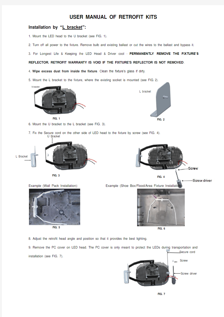
1. Mount the LED head to the U bracket (see FIG. 1).
2. Turn off all power to the fixture. Remove bulb and existing ballast or cut the wires to the ballast and bypass it.
3. For Longest Life & Keeping the LED Head & Driver cool - PERMANENTLY REMOVE THE FIXTURE’S
REFLECTOR. RETROFIT WARRANTY IS VOID IF THE FIXTURE'S REFLECTOR IS NOT REMOVED.
4. Wipe excess dust from inside the fixture. Clean the fixture’s glass if dirty.
5. Mount the L bracket to the fixture, where the existing socket is mounted (see FIG. 2).
6. Mount the U bracket to the L bracket (see FIG. 3).
7. Fix the Secure cord on the other side of LED head to the fixture by screw (see FIG. 4).
Example (Wall Pack Installation):Example (Shoe Box/Flood/Area Fixture Installation):
8. Adjust the retrofit head angle and position so that it provides the best lighting.
9. Remove the PC cover on LED head. The PC cover is only meant to protect the LEDs during transportation and
installation (see FIG. 7).
FIG. 1FIG. 2
FIG. 3FIG. 4
FIG. 5FIG. 6
L bracket
Secure cord
Screw
Screw driver
FIG. 7
U Bracket
L Bracket
MODEL _________ WATTS_______ VOLTS ________ AMPS ________ 10. BE SURE THAT NOTHING WILL TOUCH OR FALL INTO THE FAN BLADES AFTER THE FIXTURE IS MOUNTED.
Installation by “
Flat mounting plate ”:
A “flat mounting plate ”
is also provided. The “flat mounting plate ” could be used instead of the “L bracket ” above and this follows the same basic mounting steps. See (see FIG. 8 & 9).
Example (High Bay and High Mast Installation):
Wirings:
1. Install the LED driver in place of the ballast. Wire the input source to the LED driver. The proper AC input connections to the driver are marked on the driver. There is a Ground, ACN (Neutral) and ACL (Line)
2. Attach the driver output to the input wires of the LED Head: Connect Red Wire to Red Wire of the LED light, and Black Wire to Black Wire of the light.
3. Re-assemble remaining parts of the fixture and restore power.
4. Never dim a non-dimmable LED driver. Not intended for use with emergency exits.
FIG. 8 FIG. 9
FIG. 10