SKF轴承密封件解释说明
- 格式:doc
- 大小:62.50 KB
- 文档页数:2
1、SKF轴承型号的含义SKF公司的滚动轴承,滚动轴承部件及附件的完整代号由基本代号和补充代号组成。
基本代号由轴承类型代号,尺寸系列代号和内径代号构成。
表示轴承的基本类型,结构和尺寸,是轴承代号的基础。
补充代号是轴承结构形状,尺寸,公差,技术要求有改变时在基本代号左右添加的代号。
在基本代号左边添加的代号为前置代号,用以识别轴承部件,在基本代号右边添加的代号为后置代号,用以表示与原设计有区别或与现行生产的标准有差异的设计问题。
1)前置代号GS——推力圆柱滚子,推力滚针轴承座圈。
例:GS81107-推力圆柱滚子轴承81107的座圈。
K——推力滚子和保持架的组合件里。
例:K81170。
K-——符合AFBMA标准系列英制圆锥滚子轴承带滚子和保持架组件的内圈(内锥体)或外圈(锥环)。
例:K-09067——系列为09000的圆锥滚子轴承的内锥体。
L——分离型轴承的单一内圈或外圈。
例:LNU207——圆柱滚子轴承NU207的内圈。
L30207——圆锥滚子轴承30207的外圈。
R——除去单一内圈或外圈的分离型轴承。
例:RNU207——圆柱滚子轴承NU207带滚子和保持架组合件的外圈。
R30207——圆锥滚子轴承和保持架组件的内圈。
WS——推力圆柱滚子,推力滚针轴圈。
例:WS81107——推力圆柱滚子轴承81107的轴圈。
2.后置代号如果轴承代号中有数个后置代号,则这些后置代号按以下顺序分组排列:(1)内部设计,(2)外部设计,(3)保持架,(4)其他特点。
(1)(2)(3)组中的后置代号与基本代号之间留出半个汉字距;(2)组中的防尘盖和密封圈的后置代号则是例外,在后置代号前面置一个连字符“-”;(4)组中的后置代号前面置一斜线。
斜线也用来隔离下列两种情况下的两个(4)组后置代号:a. 第一个后置代号以数字结尾和第二个后置代号以数字开头时。
例:6205/P53/223316。
B. 表示压缩和(/或)移动游隙范围的后置代号后再跟一表示润滑脂类型的后置代号,若省略斜线会引起混淆时。
常见SKF轴承后缀含义SKF单列角接触球轴承后缀解释:A30°接触角AC 25°接触角B 40°接触角CA任意配对安装的轴承(通用轴承);安装前背对背配对或面对面配对时,轴向内部游隙小于普通组(CB)CB 任意配对安装的轴承(通用轴承);安装前背对背配对或面对面配对时,轴向内部游隙等于普通组CC 任意配对安装的轴承(通用轴承);安装前背对背配对或面对面配对时,轴向内部游隙大于普通组(CB)DB 两个轴承背对背配对DF 两个轴承面对面配对DT 两个轴承串联配对E 内部优化设计F 经机械加工窗型铜保持架、滚动体引导G 任意配对安装的轴承(通用轴承);背对背配对或面对面配对时,有轴向内部游隙GA任意配对安装的轴承;背对背配对或面对面配对时,安装前有较轻的预负荷GB 任意配对安装的轴承;背对背配对或面对面配对时,安装前有中等的预负荷GC 任意配对安装的轴承;背对背配对或面对面配对时,安装前有较重的预负荷J 窗型冲压钢保持架,滚动体引导M 经机械加工窗型铜保持架、滚动体引导,不同设计以一个数字区别,如:M1MB 机加工铜保持架,内圈引导N1 外圈带一个定位槽N2 外圈侧面带两个定位槽,间隔180°配置P 注模玻璃纤维增强尼龙6,6保持架,滚动体引导PH 窗型注模聚醚酮醚(PEEK)保持架,滚动体引导P5 尺寸和运行精度符合ISO公差5级标准P6 尺寸和运行精度符合ISO公差6级标准W64 固体润滑油填充Y冲压窗型铜保持架,以滚球定心SKF球面滚子轴承后缀解释:C2 径向内部游隙小于普通级C3 径向内部游隙大于普通级C4 径向内部游隙大于C3C5 径向内部游隙大于C4C08 经提高的运行精度符合ISO公差5级标准C083 C08 + C3C084 C08 + C42CS 轴承两侧带钢骨架丁腈橡胶(NBR)接触密封件。
外圈带环形槽和三个润滑孔,有聚合物带覆盖。
根据表,以极限压力油脂润滑。

看懂SKF轴承上面的型号、安装SKF轴承,这一条搞全了!江南泵阀--专业氟塑料泵--值得信赖有氟密管阀- 非金属阀门专业制造商优质弯头法兰弯管三通等管件生产企业本文章分三部分,阅读和看完视频需要近20分钟!第一部分:轴承安装视频第二部分:SKF轴承的符号解读第三部分:轴承安装规则与注意事项各种轴承的内部结构和安装要求先来了解一下SKF轴承的命名规则基本代号为22206是代表一个球面滚子轴承,宽度系列为2,外径系列也是2,内径为30mm。
SKF轴承型号前缀:IR-23232AR:球与保持架组件或滚子与保持架组件IR:径向轴承的内圈K:圆柱滚子与保持架推力组件K-:符合ABMA标准系列英制圆锥滚子轴承带滚子与保持架组件的内圈(圆锥内圈)或外圈(圆锥外圈)L:分离型轴承的内圈或外圈OR-:径向轴承的外圈R:除去内圈或外圈的分离轴承W:不锈钢深沟球轴承WF:外圈带法兰的不锈钢深沟球轴承WS:圆柱滚子推力轴承的轴圈GS——推力圆柱滚子,推力滚针轴承座圈。
L30207——圆锥滚子轴承30207的外圈。
WS——推力圆柱滚子,推力滚针轴圈。
例: WS81107——推力圆柱滚子轴承81107的轴圈。
SKF轴承型号后缀:3204-ATN9A:内部设计2RS1:外部设计TN9:保持架设计WT:变型SKF轴承型号后缀——内部设计:轴承后缀为A、B、C、D、E或其它以这些字母为字首的代号表示内部设计有差异或经改良。
基本尺寸保持不变,但一般的规定为不同的字母用于某些既定的轴承类型或系列,而其意义也不同。
例:4210A:双列深沟球轴承,不带装球缺口22314E:球面滚子轴承,经优化内部设计。
7306B:单列角接触球轴承,接触角为40度。
7205B:单列角接触球轴承,接触角40度和优化的内部设计。
SKF轴承型号后缀——外部设计:外部设计表示经改良的结构如在外圈加工凹槽以安装密封、防尘盖或止动环等。
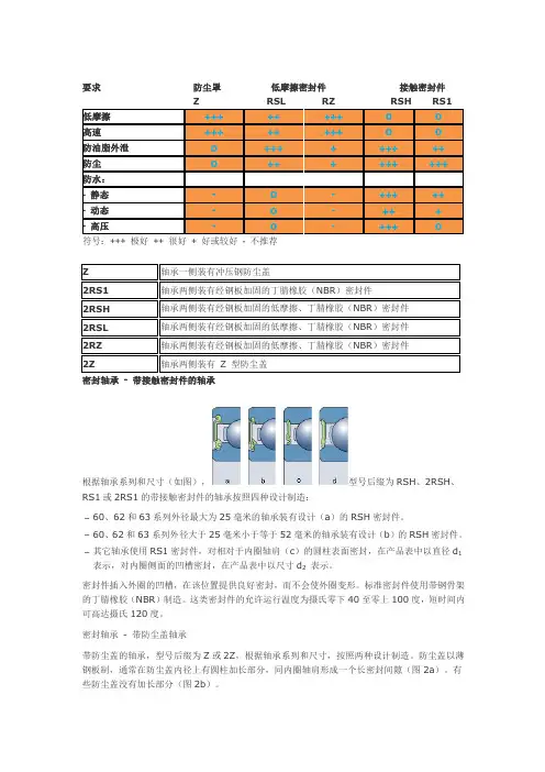
RS1或2RS1表示轴承一侧或两侧带附着冲压钢片的丙烯腈丁二烯橡胶密封。
SKF进口轴承公司概述SKF的全称是“Svenska Kullager-Fabriken”中文音译名称为“斯凯孚”;公司总部所在地:瑞典哥德堡;SKF集团总部设立于瑞典哥特堡,是轴承科技与制造的领导者。
Sven Wingquist在1905年发明了双列自动对心滚珠轴承,随即于1907年创立Svenska Kullargerfabriken瑞典滚珠轴承制造公司,简称SKF。
公司之业务即以这种机械工程史上划时代的发明为起点而蒸蒸日上。
时至今年已届满一百周年,SKF仍秉持既定宗旨,不断发展,服务世界。
SKF执世界滚动轴承业之牛耳,经营的触角已遍及全球,业务遍及世界130个国家,每年生产五亿多个轴承,销售网遍布全球。
目前拥有200家分公司、80家制造厂、41000位员工和8000家代理商和经销商。
SKF亦生产及销售轴承钢及其他高品质特殊钢。
此外,SKF集团亦持续致力于轴承工业的研究与发展,平均每两天就有一项新的专利问世。
SKF集团也是第一家通过ISO14001环保认证的轴承公司,此项认证涵盖17个国家共60多个制造单位。
1989年元月31日投审会通过SKF集团旗下的台湾子公司─斯凯孚股份有限公司的投资案,同年2月18日取得营利事业登记证,随即在台北、台中和高雄设立分公司以及成立位在三重的中心仓库,负责货物配销。
本公司销售系统整合于总部设计、规划之电脑系统中,以提供迅速、正确之服务。
我们在台湾销售由SKF原厂所生产之轴承、油封及相关产品,提供客户全面满意的产品与服务为目标。
SKF斯凯孚公司多年来深耕本地市场,营业规模稳定成长,提供客户全方位的服务。
由于SKF对于产品品质及服务水准之要求,使我们成为轴承界的领导者,其最终目标为透过品质系统运作,不断提升与进步,以永续保持市场领袖的地位,并提供客户无忧运转的服务系统。
我们主要客户群来自钢铁业、造纸、水泥、塑胶及各类OEM之制造厂商。
此外,SKF 台湾亦提供下列各项技术予客户:技术咨询与轴承选择、轴承维修、轴承配组/加工、技术训练。
SKF轴承知识大全SKF轴承简介,SKF轴承型号的含义,NSK 公司概述,SKF轴承故障排除and so on.1:SKF轴承简介:SKF的全称是“Svenska Kullager-Fabriken”中文音译名称为“斯凯孚”;SKF集团总部设立于瑞典哥特堡,是轴承科技与制造的领导者。
Sven Wingquist在1905年发明了双列自动对心滚珠轴承,随即于1907年创立Svenska Kullargerfabriken瑞典滚珠轴承制造公司,简称SKF,生产企业:105家;员工人数:约38,748人;公司数量:约150家;2007年全年净销售额为585.59亿瑞典克朗;总裁兼首席执行官CEO:汤母·强斯顿Tom Johnstone公司之业务即以这种机械工程史上划时代的发明为起点而蒸蒸日上。
时至今年已届满一百周年,SKF仍秉持既定宗旨,不断发展,服务世界。
SKF执世界滚动轴承业之牛耳,经营的触角已遍及全球,业务遍及世界130个国家,每年生产五亿多个轴承,销售网遍布全球。
目前拥有200家分公司、80家制造厂、41000位员工和8000家代理商和经销商。
SKF亦生产及销售轴承钢及其他高品质特殊钢。
此外,SKF集团亦持续致力于轴承工业的研究与发展,平均每两天就有一项新的专利问世。
SKF集团也是第一家通过ISO14001环保认证的轴承公司,此项认证涵盖17个国家共60多个制造单位。
2:SKF轴承型号的含义SKF公司的滚动轴承,滚动轴承部件及附件的完整代号由基本代号和补充代号组成。
基本代号由轴承类型代号,尺寸系列代号和内径代号构成。
表示轴承的基本类型,结构和尺寸,是轴承代号的基础。
补充代号是轴承结构形状,尺寸,公差,技术要求有改变时在基本代号左右添加的代号。
在基本代号左边添加的代号为前置代号,用以识别轴承部件,在基本代号右边添加的代号为后置代号,用以表示与原设计有区别或与现行生产的标准有差异的设计问题。
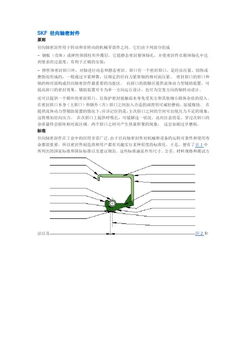
SKF 径向轴密封件原则径向轴密封件用于转动和非转动的机械零部件之间。
它们由下列部分组成–钢板(壳体)或弹性体圆柱形外覆层,它能静态密封箱体轴孔,并使密封件在箱体轴孔中达到要求的过盈度,有利于正确的安装;–弹性体密封唇口环,对轴进行动态和静态密封。
唇口有一个密封唇口,是经由压紧、切削或磨削而形成的,一般通过卡紧弹簧,以规定的径向力紧靠轴的相对面压紧。
密封唇口的唇口和轴的相对面构成径向轴密封件最重要的功能区。
向唇口的接触区提供流体动力型辅助装置,可提高唇口的密封效果。
辅助装置可专为单一方向运行设计,也可为交变方向的轴转动设计。
还可以提供一个额外的密封唇口,以保护密封接触面本身免受灰尘和其他细小固体杂质的侵入。
在密封唇口本身(主唇口)和额外(次)唇口之间加入合适的润滑剂可减轻磨损,延缓腐蚀。
在提供流体动力型辅助装置的情况下,应该记住的是,主次唇口之间的空间可出现压力不足的现象,这将增加径向压力。
在次唇口上提供呼吸孔,可缓解这一状况。
还应注意的是,穿过次唇口的杂质最终会损坏相对面区域。
两个唇口之间可产生热量积聚的现象;这会加剧过早磨损。
标准径向轴密封件在工业中的应用非常广泛。
由于径向轴密封件对机械和设备的运转可靠性和使用寿命都很重要,所以密封件制造商和用户都有兴趣实行某种程度的标准化。
于是,便有了表1中所列出的国家标准和国际标准以及建议规范。
这些标准涵盖外形尺寸、公差、材料规格和测试方法以及图2和图3中列出的专用术语,还有图4中列出的六种最常用的径向轴密封件形状。
应该注意的是,SKF出版物中和此处所用的术语与ISO的标准化术语不尽相同。
SKF和本型录中使用的术语,凡与ISO不相同的,均在图2和图3中以粗体字列于相关ISO术语之后型号体系公制径向轴密封件SKF制造的所有公制径向轴密封件的型号均以字母CR为前缀,后面是以毫米为单位的大小尺寸(未编码)和表示密封件类型与设计以及唇环材料的后缀。
英制径向轴密封件英制SKF径向轴密封件以图纸编号标识,图纸编号由四位到七位数组成。
SKF轴承型号说明前缀:GS——圆柱滚子推力轴承的座圈K——圆柱滚子-保持架推力组件K-——ABMA标准系列的英制圆锥滚子轴承内圈连滚子-保持架组件(CONE)或外圈(CUP)L——分离型轴承的内圈或外圈R——分离型轴承的内圈或外圈连滚子-保持架组件W——不锈钢深沟球轴承WS——圆柱滚子推力轴承的轴圈ZE——用于电控法安装的轴承后缀:A——经过改进或稍作改变的内部设计。
外形尺寸相同,通常对不同类型或系列的轴承有不同的意义。
例如:4210A-不带装球缺口的双列深沟球轴承;3220A-接触角为30°的双列角接触球轴承AC——接触角为25°的单列角接触球轴承ADA——外圈上的止动槽经过改进,剖分的内圈由一个固定环固定B——经过改进或稍作改变的内部设计。
外形尺寸相同,通常对不同类型或系列的轴承有不同的意义。
例如:7224B-接触角为40°的单列角接触球轴承;32210B-接触角较大的圆锥滚子轴承Bxx(x)——B与一个两位或三位数组合,用来表示一些没有合适后缀的变型。
如B20-缩窄的宽度公差C——经过改进或稍作改变的内部设计。
外形尺寸相同,通常对不同类型或系列的轴承有不同的意义。
例如:21306C-球面滚子轴承,带两个窗式冲压钢保持架、内圈无挡边和带一个由内圈引导的导圈CA——1.C型球面滚子轴承,带叉型机加工黄铜保持架、内圈两侧有挡边和带一个由内圈引导的导圈2.通用配组轴承,在背对背或面对面配置时,轴向游隙小于普通组(CB)CAC——CA型球面滚子轴承,滚子的引导经过改进CB——1. 通用配组轴承,在背对背或面对面配置时,轴向游隙为普通组2.双列角接触球轴承,特定的轴向游隙CC——1. C型球面滚子轴承,滚子的引导经过改进2. 通用配组轴承,在背对背或面对面配置时,轴向游隙大于普通组(CB)CLN——圆缀滚子轴承,缩窄套圈宽度和总宽度的公差带,符合ISO公差等级6XCL0——精度符合ANSI/ABMA19.2:1994标准公差等级0,用于英制圆锥滚子轴承CL00——精度符合ANSI/ABMA19.2:1994标准公差等级00,用于英制圆锥滚子轴承CL3——精度符合ANSI/ABMA19.2:1994标准公差等级3,用于英制圆锥滚子轴承CL7C——用于圆锥滚子轴承,有特殊的摩擦特性和更高的旋转精度CN——普通组径向游隙,通常仅用于与以下字母组合来表示较窄或偏移的游隙范围CNH-缩窄的游隙范围,相当于普通组游隙范围的上半部分CNM-缩窄的游隙范围,相当于普通组游隙范围的一半CNL-缩窄的游隙范围,相当于普通组游隙范围的下半部分CNP-偏移的游隙范围,相当于普通组游隙范围的上半部分和C3游隙范围的下半部分的组成CNR-具有符合DIN 620-4:1982的普通组游隙的圆柱滚子轴承以上的字母H、M、L和P,同时适用于以下的游隙组别合成对应的意义:C2、C3、C4和C5,如C2HCV——改进内部设计,满装圆柱滚子轴承CS——轴承一侧带具钢骨架的丁腈橡胶(NBR)接触式密封圈CS2——轴承一侧带具钢骨架的氟橡胶(FPM)接触式密封圈CS5——轴承一侧带具钢骨架的氢化丁腈橡胶(HNBR)接触式密封圈2CS——轴承两侧带具钢骨架的丁腈橡胶(NBR)接触式密封圈2CS2——轴承两侧带具钢骨架的氟橡胶(FPM)接触式密封圈2CS5——轴承两侧带具钢骨架的氢化丁腈橡胶(HNBR)接触式密封圈C1——径向游隙小于C2C2——径向游隙小于普通组(CN)C3——径向游隙大于普通组(CN)C4——径向游隙大于C3C5——径向游隙大于C4C02——缩窄的内圈旋转精度公差C04——缩窄的外圈旋转精度公差C08——C02+C04C083——C02+C04+C3C10——缩窄的内径和外径公差D——经过改进或稍作改变的内部设计。
SKF 轴承参数说明SKF 轴承常用后缀及参数说明常用后缀:CN:一般组径向游隙;通常仅用于与以下字母组合来表示较窄或偏移的游隙范围H:缩窄的游隙范围,相当于原来游隙范围的上半局部L:缩窄的游隙范围,相当于原来游隙范围的下半局部P:偏移的游隙范围,相当于原来游隙范围的上半局部和下一组游隙范围的下半局部的组成以上字母同时适用于与以下的游隙组别组合成对应的意义:C2、C3、C4、和 C5,例如 C2 C2:径向游隙小于一般组 C3:径向游隙大于一般组 C4:径向游隙大于 C3 C5:径向游隙大于 C4参数说明(1)内部设计 ACD——接触角为 25 度。
B——接触角为 40 度。
CC——接触角为 12 度。
CD——接触角为 15 度。
BE——接触角为 40 度的 BE 型轴承,钢球加大,以玻璃纤维增加尼龙 6.6 保持架。
双列角接触球轴承A——外径小于等于 90 毫米轴承的标准设计,没有装球缺口,承受玻璃纤维增加尼龙 6.6 保持架。
E——轴承一侧有装球口,可装较多钢球,因此具有较高的径向及轴向承载力量。
调心滚子轴承CAC,ECAC,CA,ECA——这些设计用于大尺寸的轴承,滚子呈对称型。
CC,C,EC——这类轴承滚子呈对称型,内圈无挡边。
E——是 SKF 公司承受最标准设计。
E 型轴承外圈带有油槽及三个油孔,则后置代号中须加W,以示区分。
圆柱滚子轴承B——轴承承受外表经处理的滚子〔满装滚子轴承〕。
B4——轴承套圈外表及滚子外表均经处理〔满装滚子轴承〕。
EC——轴承内部几何外形经改进,有较高的承载力量,挡边和滚子端面具有良好的接触和润滑条件,能承受较高的轴向载荷。
(2)外部设计CA,CB,CC——通用配对型单列角接触球轴承,可任意〔串联,面对面或背靠背〕配对安装。
背靠背或面对面排列时,轴向安装前内部间隙与正常值比:小〔CA〕,正常〔CB〕,较大〔CC〕。
-2F——外球面球轴承两侧带甩尘挡圈。
-2FF——外球面球轴承两侧带组合甩尘挡圈。
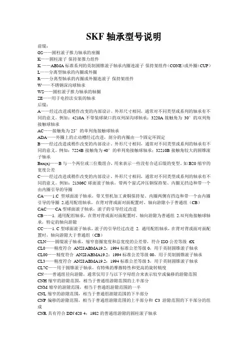
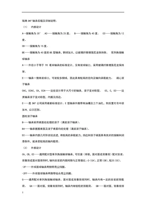
密封轴承- 带接触密封件的轴承
根据轴承系列和尺寸(如图),型号后缀为RSH、2RSH、RS1或2RS1的带接触密封件的轴承按照四种设计制造:
–60、62和63系列外径最大为25毫米的轴承装有设计(a)的RSH密封件。
–60、62和63系列外径大于25毫米小于等于52毫米的轴承装有设计(b)的RSH密封件。
–其它轴承使用RS1密封件,对相对于内圈轴肩(c)的圆柱表面密封,在产品表中以直径d1表示,对内圈侧面的凹槽密封,在产品表中以尺寸d2表示。
密封件插入外圈的凹槽,在该位置提供良好密封,而不会使外圈变形。
标准密封件使用带钢骨架的丁腈橡胶(NBR)制造。
这类密封件的允许运行温度为摄氏零下40至零上100度,短时间内可高达摄氏120度。
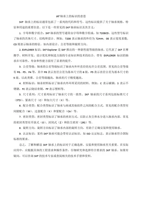
密封轴承- 带防尘盖轴承
带防尘盖的轴承,型号后缀为Z或2Z,根据轴承系列和尺寸,按照两种设计制造。
防尘盖以薄钢板制,通常在防尘盖内径上有圆柱加长部分,同内圈轴肩形成一个长密封间隙(图2a)。
有些防尘盖没有加长部分(图2b)。
带防尘盖轴承主要用于内圈旋转的应用。
如果外圈旋转,在高速应用条件下有漏脂的危险。
图2a
图2b。
瑞典SKF轴承后缀及详细说明:(1)内部设计A--接触角为30° .AC——接触角为25度。
B——接触角为40度。
CC——接触角为12度。
CD——接触角为15度。
BE——接触角为40度的BE型轴承,钢球加大,以玻璃纤维增强尼龙保持架。
双列角接触球轴承A——外径小于等于90毫米轴承的标准设计,没有装球缺口,采用玻璃纤维增强尼龙保持架。
E——轴承一侧有装球口,可装较多钢球,因此具有较高的径向及轴向承载能力。
调心滚子轴承CAC,ECAC,CA,ECA——这些设计用于大尺寸的轴承,滚子呈对称型。
CC,C,EC——这类轴承滚子呈对称型,内圈无挡边。
E——是SKF公司采用最新标准设计。
E型轴承外圈带有油槽及三个油孔,则后置代号中须加W,以示区别。
圆柱滚子轴承B——轴承采用表面经处理的滚子(满装滚子轴承)。
B4——轴承套圈表面及滚子表面均经处理(满装滚子轴承)。
EC——轴承内部几何形状经改进,有较高的承载能力,挡边和滚子端面具有良好的接触和润滑条件,能承受较高的轴向载荷。
(2)外部设计CA,CB,CC——通用配对型单列角接触球轴承,可任意(串联,面对面或背靠背)配对安装。
背靠背或面对面排列时,轴向安装前内部间隙与正常值比:小(CA),正常(CB),较大(CC)。
-2F——外球面球轴承两侧带甩尘挡圈。
-2FF——外球面球轴承两侧带组合甩尘挡圈。
G——通用配对单列角接触球轴承。
面对面或背靠背排列时,轴承内有一定的安装前预载荷。
GA——面对面,背靠背排列时,轴承内有较轻的预载荷。
GB——面对面,背靠背排列时,轴承内有中等预载荷。
GC——面对面,背靠背排列时,轴承内有较重的预载荷。
K ——圆锥孔,锥度1:12。
K30——圆锥孔,锥度1:30。
-LS——轴承一面具有接触式密封,内圈无密封凹槽。
-2LS——轴承两面具有LS密封。
N ——轴承外圈上有止动槽。
NR——轴承外圈上有止动槽并有止动环。
N2——外圈倒角上有两个直径方向上相对的槽口。
skf轴承上的标识的意思SKF轴承上的标识通常包括了一系列的代码和符号,这些标识提供了关于轴承规格、特征和用途的重要信息。
以下是一些常见的SKF轴承标识及其含义:1. 字母和数字组合:SKF轴承的型号通常由字母和数字组成,如7208CD。
这些型号标识了轴承的具体尺寸、结构和设计。
例如,7208表示轴承的外径为72mm,08表示宽度系数,CD则表示轴承的特征,如内部设计、公差等级和旋转方向。
2. EXPLORER标识:SKF Explorer是SKF推出的一种新性能等级的轴承,它代表了SKF在摩擦学、材料开发、设计优化和制造方面的专业知识和技术的结合。
带有EXPLORER标识的轴承在可靠性、寿命和性能方面有了显著的提升。
3. 公差等级:轴承的公差等级标识了轴承内外环直径的允许公差范围。
常见的公差等级有P6、P5、P4等,其中P6表示直径公差为基本尺寸的6级,P5表示直径公差为基本尺寸的5级,以此类推。
公差等级越高,轴承的尺寸精度越高。
4. 材料标识:轴承材料标识了轴承内外环所采用的材料。
例如,C表示碳钢,S表示不锈钢,FC表示烧结青铜,FP表示塑料等。
5. 尺寸系列:尺寸系列标识了轴承尺寸的一致性。
SKF轴承的尺寸系列包括标准尺寸(STD)、紧凑尺寸(C)和加大尺寸(X)等。
6. 配合类型:配合类型标识了轴承与座或其他组件之间的配合方式。
常见的配合类型有间隙配合(M)、过盈配合(K)和紧配合(CA)等。
7. 密封类型:密封类型标识了轴承的密封方式,以防止灰尘和水分进入轴承内部。
常见的密封类型有开放式(O)、封闭式(Z)和防尘密封(2RS)等。
8. 旋转方向:旋转方向标识了轴承内部的旋转方向,有助于正确安装和使用轴承。
9. 认证标识:某些SKF轴承可能会带有认证标识,如ISO认证标志,表示轴承符合国际标准的要求。
总之,了解和解读SKF轴承上的标识对于正确选择、安装和使用轴承至关重要。
在实际应用中,应根据具体的工程需求和操作条件,仔细研究和选择符合要求的SKF轴承。
Bearing basicsSpecial Notes for iPad UsersFor iPad users, this course plays in the “Articulate mobile player app”, available free from the App store.The app offers a download option for offline learning, but please note that:1. An on-line connection is required to use the links on the “resources” tab2. If you wish to be able to print your course completion certificate then you need to be on-line when you take the end-of-course testTo continue, you can click the Home icon on the screen to return to the Welcome page of the course.WelcomeWelcome to the Basic introduction to rolling bearings course. This course will give you an introduction to SKF bearings and consists of three sections: Functions and parts,Applications and bearing types,and Designations.Module 1: Functions and partsWhy bearings?Bearings are an essential component of almost all machinery. They transmit loads between, support, guide and locate, machine elements that are required to move relative to each other with a minimum of friction, e.g.a rotating or oscillating shaft, pivot or wheel.Friction: Page 1Friction counteracts the movement between two surfaces. It is essential for the success of many operations, such as a car tyre gripping a road. In most machines however, friction is undesirable since it causes power loss, heat generation, wear and noise. SKF bearings help reduce friction.Friction: Page 2The earliest bearings were mostly made of wood and consisted of a shaft rotating in a hole in a housing, or a wheel rotating on a stationary shaft. Because the components were sliding over each other, friction was relatively high and wear rather rapid.This type of bearing is called a plain bearing and, made of modern materials, is still used in some applications today where speeds and loads are relatively low.Friction: Page 3The introduction of rolling elements between the shaft and the housing greatly reduces friction.Friction: Page 4Today, typical SKF rolling bearings combine maximum load capacity with minimum friction, using hardened steel or ceramic rolling elements, hardened steel inner and outer rings and a cage to guide and separate the rolling elements.Loads: Page 1A bearing can be under radial load, perpendicular to the shaft, or under axial load, acting in the direction along the shaft, or a combination of both radial and axial load, a combined load.Loads: Page 2Large bearings support heavier loads than small bearings can support, and roller bearings support heavier loads than ball bearings can support. Raceway contactThe basic difference between ball bearings and roller bearings is in the contacts between the rolling elements and the raceways. Balls have point contact; rollers have linear contact with relatively larger area.Bearing partsA typical rolling bearing consists of an inner ring, an outer ring and rolling elements contained by a cage. The most common type of rolling bearing is the deep groove ball bearing. These bearings can, as shown here, be supplied with integral seals to retain the lubricant and resist the ingress of contamination.Selection factorsThere are many factors, which will affect the choice of a bearing. These are: Available space, load, required service life, misalignment, speed, stiffness, axial displacement and clearance.Selection factors: SpaceSpace can be an important factor in bearing selection. Where radial space is limited a bearing with small diameter rolling elements, such as a needle roller bearing, may be needed.Selection factors: LoadWhen selecting a bearing, it is important to consider the direction of the load, and the amount of load the bearing will have to carry. A bearing can be under radial load, axial load, or a combination of both.Selection factors: Required service lifeThe life of a bearing can be expressed in terms of: the number of revolutions before failure, the number of operating hours before failure, or the distance covered (for cars and trucks). A bearing is considered to have failed when it shows the first sign of fatigue in a rolling element or raceway, or damage to other parts such as the cage or the seals. Service life is the real life that an individual bearing achieves in a particular application before it has to be replaced. It depends on a variety of influencing factors, including lubrication, the degree of contamination, misalignment, proper installation, and environmental conditions.Because service life cannot be calculated or predicted, bearings are selected using calculated rating life. SKF rating life L10m, a reference value calculated according to statistical methods, using modification factors for lubrication conditions and degree of contamination, and applying the same concept of a fatigue load limit as used in ISO 281, to estimate the life, with 90% reliability, that a sufficiently large population of apparently identical bearings might achieve when all are operating in an identical application.Selection factors: MisalignmentWhere a bearing is likely to be subject to angular misalignment, for example the shaft might bend due to operating loads, appropriate bearings need to be selected. Self-aligning bearings can accept a degree of operational misalignment and can also compensate for limited initial alignment errors in mounting.Selection factors: SpeedThe maximum speed that a bearing can be run in an application is limited by the maximum operating temperature for the materials used in its manufacture, or the lubricant. For high-speed applications minimum possible friction is important, so ball bearings are generally used. Selection factors: StiffnessElastic deformation occurs under load. Usually this deformation is very small and can be ignored. However, in some applications, stiffness is an important factor. Roller bearings have higher stiffness than ball bearings due to the larger area of the line contact.Selection factors: Axial displacementSome applications require bearings that allow the shaft to move axially relative to the bearing. This is called axial displacement. Most often, a shaft is supported by a locating bearing and a non-locating bearing. The locating bearing does not allow axial displacement and keeps the shaft in position. The non-locating bearing supports the shaft and allows displacement to prevent the bearings from being stressed. Cylindrical and CARB toroidalroller bearings can accommodate a limited degree of axial internal displacement.Selection factors: ClearanceThe amount of initial internal radial clearance required in a bearing depends mainly on the fits and temperature gradient between the inner and outer rings of the bearing in the particular application. Operational internal radial clearance is almost always less than initial internal clearance. SKF manufactures bearings with the following ranges of radial internal clearances:•C1 radial internal clearance less than C2•C2 radial internal clearance less than Normal•-- Normal radial internal clearance•C3 radial internal clearance greater than Normal•C4 radial internal clearance greater than C3SummaryIn this lesson, you have learnt about the functions of a bearing. These are: reducing friction, transmitting loads, locating and guiding moving parts. You have also been introduced to the different parts of a bearing: outer and inner rings, rolling elements, cage, and seals and their respective functionalities.Finally, you have also explored the different selection factors, which will affect your choice of bearing: available space, load, required service life, misalignment, speed, stiffness, axial displacement and clearance.Module 2: ApplicationsIntroductionIn this section you will be introduced to the most common bearing types offered by SKF.Electrical motors can be found almost anywhere there is mechanical movement.Motor: Page 2In this drawing you can see that the shaft is supported by two different bearings.Motor: Page 3Cylindrical roller bearings are simply bearings with cylindrical rollers. They can usually accommodate heavy radial loads and can operate at relatively high speeds.Motor: Page 4It is now time to choose the right side bearing.Motor: Page 5Deep groove ball bearings have deep uninterrupted raceways and close osculation between balls and raceways. This enables them to take axial loads in both directions.Pump: Page 1A pump is a device for lifting, transferring or moving fluids by suction or pressure from one position to another. This picture shows a medium-duty process pump, which is often used in refineries.Pump: Page 2In this drawing you can see that the shaft, which is running the impeller, is supported by one deep groove ball bearing to the right, and another bearing or bearings to the left.Single row angular contact ball bearings are widely used in medium and heavy-duty centrifugal pumps. They have raceways arranged at an angle to the bearing axis.Pump: Page 4Single row angular contact ball bearings can only take axial load in one direction. Therefore they are nearly always mounted as pairs in back to back or face to face arrangement at either end of a shaft, or as shown here, universally matchable bearings mounted immediately adjacent to each other.Fan: Page 1This is an industrial fan, in which SKF bearings are commonly used. Industrial fans can either be designed for light loads and high speeds, or for heavy loads and moderate speeds.Fan: Page2A fan is designed with two bearings along its shaft, placed between the fan and the motor. Both bearings carry radial loads and the bearing closest to the fan (on the left hand side here) also needs to be a locating bearing, keeping the shaft and the fan in a fixed position.Fan: Page 3Spherical roller bearings have two rows of rollers with a common raceway in the outer ring. The two inner ring raceways are inclined at an angle to the bearing axis.Fan: Page 4Returning to the fan application again, you now know which bearing is suitable as the locating bearing and here you have to make a guess concerning the non-locating bearing.CARB [ka:b] is a single row toroidal roller bearing with long, slightly crowned, rollers and concave raceways in both the inner and outer rings. Fan: Page 6The complete application looks like this with one spherical roller bearing and one CARB toroidal roller bearing.Separator: Page 1Alfa Laval, a Swedish company, has developed a range of machines specifically designed for rigorous oil processing duties. An example of this would be separators.Separator: Page 2The separation process creates imbalance due to the mud, which is distributed unevenly inside the separator and this makes the spindle bend. Separator: Page 3Self-aligning ball bearings have two rows of balls and a common concave sphered raceway in the outer ring. This makes the bearing insensitive to angular misalignments of the shaft relative to the housing. Self-aligning ball bearings accommodate high speeds due to the point contact between balls and raceways.Refiner: Page 1SKF bearings can be used in refiners in the production of mechanical pulp and other high-yield pulps.Refiner: Page 2In the process wood chips are ground at high mechanical pressure between a stationary disc and a rotating disc, which is powered by an electrical motor. The shaft between the motor and the grinding discs is supported by three bearings.Refiner: Page 3The high production capacity of the refiners is directly related to the demands on the bearing arrangement. The bearings have to provide high stability, operate at high speed, carry high thrust loads and handle deflections of the shaft.Refiner: Page 4The spherical roller thrust bearing incorporates a large number of asymmetrical, spherical rollers and has specially designed raceways. The load is transmitted from one raceway to the other at an angle to the bearing axis and the bearing can carry heavy axial load in one direction and some simultaneously applied radial load as well.Refiner: Page 5This is how the spherical roller thrust bearings are situated in the refiner application.Screw conveyor: Page 1Machines used in the agricultural industry often require bearings that can easily be changed and that can handle misalignments.Screw conveyor: Page 2This is a drawing of a screw conveyor attached to an agricultural machine. The bearings are the only contact between the screw conveyor and the machine.Screw conveyor: Page 3A Y-bearing unit consists of two parts: a housing and a bearing. The bearing is based on the deep groove ball bearing and can carry light radial and axial loads. It has a convex-sphered outside diameter, which allows the bearing to take up misalignment between the shaft and housing at the assembly stage. They are available with a wide range of highly effective,integral seals and a range of different methods for easy mounting to the shaft.Screw conveyor: Page 4This is what the Y-bearing unit looks like in the screw conveyor.Front wheel: Page 1SKF bearings are used in front wheels of commercial vehicles. These applications require bearings that can handle very heavy loads.Front wheel: Page 2This drawing shows how a truck front wheel arrangement is designed and where its bearings are situated. The bearings must carry a large part of the weight of the vehicle and the induced forces when driving, which means that they have to handle heavy loads in both radial and axial directions.Front wheel: Page 3Tapered roller bearings have tapered rollers running in tapered inner and outer ring raceways. This design makes them suitable for handling heavy combined loads.A tapered roller bearing can only carry axial loads in one direction and, for this reason, they are generally fitted in pairs.Front wheel: Page 4See how the tapered roller bearings are mounted in the front wheel of a commercial vehicle.SummaryIn this lesson, you have studied the most common SKF bearing types. Now click on each bearing picture to repeat the most important characteristics of each type. If you want to read more about SKF bearings, enter the SKF Interactive Engineering Catalogue on line at .Module 3: DesignationsIntroductionSKF bearing designations describe a bearing’s or component’s type, design, and variants. The designation can be found both on the box and on the bearing itself.Basic designations: Page 1A bearing designation for metric size bearings can either consist of a basic designation alone or a basic designation plus one or more supplementary designations, called prefixes and suffixes.The basic designation identifies the product type and size, while the supplementary designations identify design, special variants and bearing components.Basic designations: Page 2Each SKF bearing of standard metric design is given a basic designation, which normally consists of three, four or five figures.Basic designations: Page 3For example, the basic designation 22206 denotes a spherical roller bearing with the width series 2, diameter series 2 and a bore diameter of 30 mm.Supplementary designations: Page 1The supplementary designations consist of both prefixes and suffixes. Supplementary designations: Page 2Prefixes are used to identify component parts of a bearing and are usually followed by the designation of the complete bearing.Supplementary designations: Page 3Suffixes are used to identify designs, which differ in some way from the original design. The suffixes are divided into four main groups: Internal design, external design, cage design and variants, all of which are added to the basic designation in this order.End of course testNow it’s time to see what you learned.If you pass the test on-line then you’ll be able to print your course completion certificate.。
skf轴承讲解SKF轴承是世界著名的轴承品牌,具有优质的设计、制造和服务能力。
本文将从SKF轴承的背景介绍、产品特点和应用领域等方面进行详细讲解。
一、SKF轴承的背景介绍SKF是瑞典SKF集团的注册商标,成立于1907年。
SKF集团是全球领先的轴承和密封制造商,拥有全球超过130个生产基地和销售公司,遍布全球140多个国家。
SKF轴承以其高质量、高性能和长寿命而享誉全球,被广泛应用于机械设备、汽车、航空航天等领域。
二、SKF轴承的产品特点1. 高质量材料:SKF轴承采用优质钢材制造,具有出色的耐磨、耐腐蚀和耐高温性能。
2. 精确制造工艺:SKF轴承采用先进的制造工艺,确保产品的精度和可靠性。
3. 高速旋转能力:SKF轴承采用优化的设计,能够在高速旋转时保持较低的摩擦和振动。
4. 长寿命:SKF轴承采用特殊的润滑技术和密封设计,延长了轴承的使用寿命。
5. 轴承型号齐全:SKF轴承提供各种类型和规格的轴承,满足不同应用领域的需求。
三、SKF轴承的应用领域1. 机械设备:SKF轴承广泛应用于各类机械设备,如电动机、风力发电机、水泵、机床等。
其高质量和可靠性能确保了机械设备的正常运行和长寿命。
2. 汽车工业:SKF轴承在汽车发动机、变速器、悬挂系统等部位得到广泛应用。
其高速旋转能力和长寿命特点使汽车在高速行驶时具有更好的稳定性和可靠性。
3. 航空航天:SKF轴承在航空航天领域的应用也非常广泛。
其轻量化、高速旋转和耐高温等特点使得飞机、卫星等航空器具有更高的性能和可靠性。
4. 钢铁工业:SKF轴承在钢铁工业中的连铸机、轧机等设备中得到广泛应用。
其高负荷能力和耐磨性能保证了设备的正常运行和高效生产。
SKF轴承作为全球著名的轴承品牌,凭借其高质量、高性能和长寿命的特点,在机械设备、汽车、航空航天等领域得到广泛应用。
无论是在普通家用电器中还是在高速列车、飞机等高强度工程设备中,SKF轴承都发挥着重要作用,为各行各业的发展提供了可靠的支持。
美国SKF轴承-CR油封的产品尺寸表及简介CR是世界领先的密封件供应商,其密封件用于卡车CR油封〔Q:2297-44253307〕、汽车、农业机械和加工工具等工业的流体密封设施。
CR也制造用于航空领域、建筑机械、家用电器和各类泵、液压系统、电机和相关配件的密封产品。
CR可以提供超过3000种单独设计的密封,有超过25000种不同唇口的原料以及规格从3.2mm到4572mm(0.125inch到180inch)的品种.这些根本的品种包括金属包覆、全橡胶和装配式的设计。
CR不断致力于密封技术的研究。
以提高产品的工作表现和可靠性。
自1990年,CR成为SKF集团的一局部。
SKF是在滚动轴承技术领域享有领导声誉的跨国公司, 这种轴承与密封有机的结合为公司在创新设计和开拓市场方面打下了坚实的根底。
例如CR Scotseal 密封和SKF轴承结合在一起时,就是CR ScotsealHubcap,组成了CR轮毂系统。
此外其他一些密封件公司也参加了集团,如意大利RFT公司,德国CR Elastomere GmbH公司。
自1928年取得第一个汽车轮毂密封专利以来,CR今天已开展成为在广阔的工程领域内的世界性技术基地。
CR的创新技术和重点围绕客户的需求,将为客户提供更加合理的进一步密封解决方案。
SKF机械密封件包含两个一样的密封件圈和两个相似的丁腈橡胶Belleville垫圈。
密封环用耐磨损和耐腐蚀和钢制成,具有精细光洁度的滑动和密封外表。
甚至能对稀油进展密封,如SAE 10W40油。
丁腈橡胶的Belleville垫圈(杯形弹簧) 在内孔和外径之间提供必要的均匀面加载和良好的密封。
垫圈的外径与随其所安装的内孔的形状而变,对外表光洁度没有特别的要求。
SKF机械密封件是作为可现成安装的密封套组件提供应用户。
一个特殊的固定环将密封环的外表靠在一起。
这不仅方便了安装,而且保护密封件不致受损坏。
固定环在安装后保存在位,在初始操作阶段为滑动外表提供附加的保护。
SKF轴承孔密封的结构及作用SKF轴承KF的全称是“Svenska Kullager-Fabriken”中文音译名称为“斯凯孚”;SKF集团总部设立于瑞典哥特堡,是轴承科技与制造的领导者。
Sven Wingquist在1905年发明了双列自动对心滚珠轴承,随即于1907年创立Svenska Kullargerfabriken瑞典滚珠轴承制造公司,简称SKF,不断发展,服务世界。
SKF执世界滚动轴承业之牛耳,经营的触角已遍及全球,业务遍及世界130个国家,每年生产五亿多个轴承,销售网遍布全球。
此外,SKF集团亦持续致力于轴承工业的研究与发展,平均每两天就有一项新的专利问世。
1989年元月31日投审会通过SKF集团旗下的台湾子公司─斯凯孚股份有限公司的投资案,同年2月18日取得营利事业登记证,随即在台北、台中和高雄设立分公司以及成立位在三重的中心仓库,负责货物配销。
本公司销售系统整合于总部设计、规划之电脑系统中,以提供迅速、正确之服务。
我们在台湾销售由SKF原厂所生产之轴承、油封及相关产品,提供客户全面满意的产品与服务为目标。
斯凯孚公司主要客户群来自钢铁业、造纸、水泥、塑胶及各类OEM之制造厂商。
此外,SKF 台湾亦提供下列各项技术予客户:技术咨询与轴承选择、轴承维修、轴承配组/加工、技术训练。
对于公司未来展望,将由原本轴承供应商,转变成结合直线滑轨、油封、润滑油品及远端侦测、系统维护等多元化公司,并已陆续为国内多家业者,成功设计开发各式轴心,从设计开发、制造组装到运转量测或维修设备,都能为客户提供完整服务。
此外,为了创造客户的价值及提供台湾市场客户的服务水准并树立轴承服务的典范,施行全系列的服务,更是让客户机械运转高枕无忧。
将其训练有素的技术服务群分配在北中南,提供轴承的应用工程知识与技术讲习,带给客户最先进的轴承选用软体、装拆保养工具、监测设备与技术咨询、线上动平衡、雷射对心,乃至于降低全厂设备停机损失的整厂维护解决对策。
Bearing Handbook for Electric MotorsContentsBearing Installation Tips ................................................................... 2, 3 Speed Ratings ......................................................................................4, 5 6200 and 6300 Series ............................................................ 6, 7 N, NJ, NU 200 EC and 300 EC Series .................................. 8, 9 Shaft and Housing Diameters6200 Series (10)6300 Series (11)N, NJ, NU 200 EC Series (12)N, NJ, NU 300 EC Series (13)Shaft Shoulder Dimensions6200 Series (14)6300 Series (15)Minimum Radial LoadN, NJ, NU 200 EC Series (16)N, NJ, NU 300 EC Series (17)Grease Relube Recommendations6200 Series (18)6300 Series (19)N, NJ, NU 200 EC Series (20)N, NJ, NU 300 EC Series (21)Vibration Frequencies6200 Series (22)6300 Series (23)N, NJ, NU 200 EC Series (24)N, NJ, NU 300 EC Series (25)ABMA-SKF Product Comparison ................................................26, 2721. Handle with care. Never pound directly on a bearing or ring. If a bearing is dropped, it is best not to install it. Store bearings horizontally in a dry place in their original unopened package and never place bearings on a dirty surface; periodically turn over sealed and shielded bearings to prevent grease from settling to one side.2. Inspect the shaft and housing. Check for size and damage; remove nicks and burrs with emery paper, and wipe clean with a soft cloth. Replace or repair shafts and housings showing obvious signs of wear or damage. A shaft placed in a vise for mounting should be protected from vise jaws with a sheet of soft metal.3. Avoid overheating. During heat-mounting operations, never bring a flame in direct contact with the bearing and never heat beyond 230° F. Also, immediately hold a heat-mounted bearing in place against the shaft shoulder until it cools and locks in place. Otherwise, the bearing may creep away from the proper position.4. Use identical replacement bearings. Replacement bearings should be identical to the bearings they replace. Contact an SKF Authorized Distributor or SKF for interchange information.5. Use the right tool for the job. Induction heaters, oil injection kits, and hydraulic nuts are among the specialized tools available for mounting and dismounting bearings over 4 in. O.D. Their use lowers the possibility of damaging bearings and speeds the process.6. Pay attention to the bearing’s press fit. For bearings with an O.D. less than 4 inches, cold mounting with a press or appropriate mounting tool is acceptable. Pressure should be applied to the ring with the inter-ference fit, or both the inner ring and outer ring simultaneously to avoid Brinelling the raceways. Applying pressure to the ring with the loose fit only will Brinell the raceways and result in noise and potentially premature failure.Installation tips forreliable bearing operation7. The contact between the bearing ring and a properly machined and dimensioned bearing seat should not require the use of bonding agents to prevent movement or turning.8. Don’t wash new bearings. Bearing manufacturers take great care to package and ship bearings that are dirt-free and ready for lubrication. There’s usually no need to wash them or remove the protective slushing compound.9. Proper lubrication is critical. Bearing manufacturers evaluate several factors before determining the type of lubricant required for specific bearings. Be sure to follow their recommendations. Temperature and contamination conditions will influence the frequency of lubrication changes.10. Rotate idle bearings. Bearings installed in equipment that is subject to vibration while the shafts are stationary may incur false brinel-ling damage, which also occurs when equipment is not properly protected during shipment. It can appear as bright, polished depressions on the inner and/or outer races, as well as on the rolling elements.11. Look for danger signs. Keep alert for three sure signs of improper bearing operation: excessive noise and increases in vibration and tem-perature. Troubleshooting instruments like hand-held vibration pens, digital thermometers, and electronic stethoscopes help spot bearingsin poor operating conditions.12. Find the cause of bearing failures. Bearings are built to last, so frequent failures may point to an installation or lubrication problem. SKF bearing analysis experts can identify the cause of bearing failure and help you prevent it in the future.3Speed ratingsThere is a speed limit to which rolling bearings can be operated. Generally, it is the operating temperature that can be permitted with respect to the lubricant being used or to the material of the bearing components that sets the limit. The speed at which this limiting bearing temperature is reached depends on the frictional heat generated in the bearing (including any exter-nally applied heat) and the amount of heat that can be transported away from the bearing. Bearing type and size, internal design, load, lubrication and cooling conditions as well as cage design, accuracy and internal clearance all play a part in determining speed capability. In the accompanying tables two speeds are listed: (Thermal) Reference Speed and (Kinematic) Limiting Speed. Warning: The new Reference and Limiting Speeds are not to be used as a direct substitution for the previous Oil and Grease speed ratings. Consult SKF to determine the actual reference speed limit for your operating conditions. Reference speedsThe reference speed for a given bearing represents the permissible operating speed of said bearing when subjected to the specific operating conditions of load, lubrication type and method as outlined in ISO 15312. This standard has been established for oil lubrication but is also valid for grease and uses the following reference conditions:• A temperature increase of 90° F (50° C) above an ambient temperature of 68° F (20° C), (thus a bearing temperature of 158° F (70° C), measured on the bearing stationary outer ring or housing washer.• R adial bearing: a constant radial load, being 5% of the basic static load rating C o.•T hrust bearing: a constant axial load, being 2% of the basic static load rating C o.• O pen bearings with Normal clearance.For oil lubricated bearings:• L ubricant: mineral oil without EP-additives having a kinematic viscosity at 158° F (70° C) of: v = 12 mm2/s (ISO VG32) for radial bearings, and v = 24 mm2/s (ISO VG68) for thrust roller bearings• O il bath with the oil reaching up to the middle of the rolling elementin the lowest position.For grease lubricated bearings:• R egular lithium soap grease with mineral base oil having a viscosityof 100 to 200 mm2/s at 104° F (40° C) (e.g. ISO VG 150).• F illing approximately 30% of the free space in the bearing.The reference temperature will be reached after 10 to 20 hours running time. Under these specific conditions the reference speed for oil and grease lubrication will be equal.4Speeds above the reference speedIt is possible to operate bearings at speeds above the reference speed if the friction within the bearing can be reduced, for example by lubrication systems with small, accurately measured quantities of lubricant or when heat can be removed from the bearing by circulating oil lubrication with cooling of the oil, by cooling ribs on the housing, or by directed cooling air streams.Any increase in speed above the reference speed without taking any of these precautions would only cause bearing temperature to rise exces-sively. An increase of bearing temperature means that lubricant viscosity is lowered and film formation is made more difficult, leading to even higher friction and further temperature increases. If, at the same time, the operational clearance in the bearing is reduced because of increased inner ring temperature, the final consequence would be bearing seizure. Limiting speedsThe speed limit is determined by criteria that include: the stability and or strength of the cage, lubrication of cage guiding surfaces, centrifugal and gyratory forces acting on the rolling elements, and other speed-limiting factors. Experience gained from laboratory tests and practical applications indicates that there are maximum speeds that should not be exceeded for technical reasons or because of the very high costs involved.Limiting Speeds shown in the tables are based on the demands of high speed running applications and are valid only for the specific design and cage design shown in the tables. It is possible to run bearings faster than the limiting speeds, but several factors must be reviewed and improved such as the running accuracy, cage material, lubrication, heat dissipa-tion and design of the bearing. It is therefore advisable to contact SKF Applications Engineering for advice. For enclosed and open bearings using grease lubrication, additional parameters have to be considered such as lubrication of cage guiding surfaces and the shear strength of the lubri-cant, which is determined by the base oil and thickener.Open ball bearings with low friction typically have Reference Speeds greater than the Limiting Speed. In these cases the permissible speed must be calculated from the operating conditions and the lower value between the permissible and Limiting speed used.5620017,00028,00034,00056,000620115,00026,00032,00050,000620213,00022,00028,00043,000620312,00019,00024,00038,000620410,00017,00020,00032,00062058,50014,00018,00028,00062067,50012,00015,00024,00062076,30010,00013,00020,00062085,6009,00011,00018,00062095,0008,50011,00017,00062104,8008,00010,00015,00062114,3007,0009,00014,00062124,0006,3008,00013,00062133,6006,0007,50012,00062143,4005,6007,00011,00062153,2005,3006,70010,00062163,0004,8006,0009,50062172,8004,5005,6009,00062182,6004,3005,3008,50062192,4004,0005,0008,00062202,4003,8004,8007,50062212,2003,6004,5007,0006222 –3,4004,3006,7006224 –3,2004,0006,3006226 –3,0003,6005,6006228 – –3,4005,3006230 – –3,2005,0006232 – –3,0004,5006234 – –3,8004,3006236 ––3,6004,0006238 – –3,4003,8006240––3,2003,6006Warning: The new reference and limiting speeds are not to be used as a direct substitution for the previous oil and grease speed ratings. See page 4/5 or contact SKF Applications Engineering.630015,00026,00032,000 50,000630114,00022,00028,000 45,000630212,00019,00024,000 38,000630311,00017,00022,000 34,00063049,50015,00019,000 30,00063057,50013,00016,000 24,00063066,30011,00013,000 20,00063076,0009,50012,000 19,00063085,0008,50011,000 17,00063094,5007,5009,500 15,00063104,3006,7008,500 13,00063113,8006,3008,000 12,00063123,4005,6007,000 11,00063133,2005,3006,700 10,00063143,0005,0006,300 9,50063152,8004,5005,600 9,00063162,6004,3005,300 8,50063172,4004,0005,000 8,00063182,4003,8004,800 7,50063192,2003,6004,500 7,0006320 –3,4004,300 6,7006321 –3,2004,000 6,3006322 – –3,800 6,0006324 –3,400 5,6006326– –3,200 5,000 –6328 – –4,300 4,8006330 – –4,000 4,3006332 – –3,800 4,0006334 –3,400 3,8006336– –3,200 3,600 –6338––3,0003,4007Note: Low-friction seals (2RZ, 2RSL) and double shielded (2Z) bearings use same speed ratings. Single enclosure (Z, RSL, RZ) and open bearings use the same speed ratings. reference limiting speed speed Bearing r/min r/min 202 EC22,00026,000 203 EC19,00022,000 204 EC16,00019,000 205 EC14,00016,000 206 EC13,00014,000 207 EC11,00012,000 208 EC9,50011,000 209 EC9,0009,500 210 EC8,5009,000 211 EC7,5008,000 212 EC6,7007,500 213 EC6,3006,700 214 EC6,0006,300 215 EC5,6006,000 216 EC5,3005,600 217 EC4,8005,300 218 EC4,5005,000 219 EC4,3004,800 220 EC4,0004,500 221 EC3,8004,300 222 EC3,6004,000 224 EC3,4003,600 226 EC3,2003,400 228 EC2,8003,200 230 EC2,6002,800 232 EC2,4002,600 234 EC2,2002,400 236 ECMA2,2003,200 238 ECMA2,0003,000 240 ECMA1,9002,800Warning: The new reference and limiting speeds are not to be used as a direct substitution for the previous oil and grease speed ratings. See page 4/5 or contact SKF Applications Engineering.8 reference limiting speed speed Bearing r/min r/min 303 EC 15,00020,000 304 EC 15,00018,000 305 EC 12,00015,000 306 EC 11,00012,000 307 EC 9,50011,000 308 EC 8,0009,500 309 EC 7,5008,500 310 EC 6,7008,000 311 EC 6,0007,000 312 EC 5,6006,700 313 EC 5,3006,000 314 EC 4,8005,600 315 EC 4,5005,300 316 EC 4,3005,000 317 EC 4,0004,800 318 EC 3,8004,500 319 EC 3,6004,300 320 EC 3,2003,800 321 EC 3,2003,800 322 EC 3,0003,400 324 EC 2,8003,200 326 EC 2,4003,000 328 EC 2,4002,800 330 EC 2,2002,600 332 EC 2,0002,400 334 EC 1,7002,200 336 EC 1,6002,200 338 EC 1,5002,000 340 ECMA1,4002,400Speed ratings (RPM) Cylindrical roller bearings N, NJ, NU 300 EC seriesBearing brg. bore dia.shaft dia. (in.)ISO toler- ancebrg. outside dia.housing dia. (in.) (ISO tolerance H6) (mm)max.min.(mm)max.min.6200100.39390.3936j530 1.1816 1.1811 6201120.47260.4723j532 1.2604 1.2598 6202150.59080.5905j535 1.3786 1.3780 6203170.66950.6692j540 1.5754 1.5748 6204200.78780.7875k547 1.8510 1.8504 6205250.98470.9844k552 2.0479 2.0472 620630 1.1815 1.1812k562 2.4416 2.4409 620735 1.3785 1.3781k572 2.8353 2.8346 620840 1.5753 1.5749k580 3.1503 3.1496 620945 1.7722 1.7718k585 3.3474 3.3465 621050 1.9690 1.9686k590 3.5442 3.5433 621155 2.1660 2.1655k5100 3.9379 3.9370 621260 2.3628 2.3623k5110 4.3316 4.3307 621365 2.5597 2.5592k5120 4.7253 4.7244 621470 2.7565 2.7560k5125 4.9223 4.9213 621575 2.9534 2.9529k5130 5.1191 5.1181 621680 3.1502 3.1497k5140 5.5128 5.5118 621785 3.3472 3.3466k5150 5.9065 5.9055 621890 3.5440 3.5434k5160 6.3002 6.2992 621995 3.7409 3.7403k5170 6.6939 6.6929 6220100 3.9377 3.9371k51807.08767.0866 6221105 4.1350 4.1344m51907.48147.4803 6222110 4.3318 4.3312m52007.87517.8740 6224120 4.7255 4.7249m52158.46578.4646 6226130 5.1194 5.1187m52309.05629.0551 ******* 5.5131 5.5124m52509.84369.8425 6230150 5.9071 5.9061m627010.631210.6299 6232160 6.3008 6.2998m629011.418611.4173 6234170 6.6945 6.6935m631012.206012.2047 62361807.08827.0872m632012.599812.5984 62381907.48217.4810m634013.387213.3858 62402007.87587.8747m636014.174614.1732Note: Diameters shown are based on normal loads, operating temperatures, and currentBearing brg. bore dia.shaft dia. (in.)ISO toler- ancebrg. outside dia.housing dia. (in.) (ISO tolerance H6) (mm)max.min.(mm)max.min.6300100.39390.3936j535 1.3786 1.3780 6301120.47260.4723j537 1.4573 1.4567 6302150.59080.5905j542 1.6541 1.6535 6303170.66950.6692j547 1.8510 1.8504 6304200.78780.7875k552 2.0479 2.0472 *******.98470.9844k562 2.4416 2.4409 630630 1.1815 1.1812k572 2.8353 2.8346 630735 1.3785 1.3781k580 3.1503 3.1496 630840 1.5753 1.5749k590 3.5442 3.5433 630945 1.7722 1.7718k5100 3.9379 3.9370 631050 1.9690 1.9686k5110 4.3316 4.3307 631155 2.1660 2.1655k5120 4.7253 4.7244 631260 2.3628 2.3623k5130 5.1191 5.1181 631365 2.5597 2.5592k5140 5.5128 5.5118 631470 2.7565 2.7560k5150 5.9065 5.9055 631575 2.9534 2.9529k5160 6.3002 6.2992 631680 3.1502 3.1497k5170 6.6939 6.6929 631785 3.3472 3.3466k51807.08767.0866 631890 3.5440 3.5434k51907.48147.4803 631995 3.7409 3.7403k52007.87517.8740 6320100 3.9377 3.9371k52158.46578.4646 6321105 4.1350 4.1344m52258.85948.8583 6322110 4.3318 4.3312m52409.44999.4488 6324120 4.7255 4.7249m526010.237510.2362 6326130 5.1194 5.1187m528011.024911.0236 6328140 5.5131 5.5124m530011.812311.8110 6330150 5.9071 5.9061m632012.599812.5984 6332160 6.3008 6.2998m634013.387213.3858 6334170 6.6945 6.6935m636014.174614.1732 63361807.08827.0872m638014.962014.9606 63381907.48217.4810m640015.749415.7480 63402007.87587.8747m642016.537016.5354Note: Diameters shown are based on normal loads, operating temperatures, and current202 150.59110.5906k6 35 1.3786 1.3780203 170.66980.6693k6 40 1.5754 1.5748204 200.78800.7875k6 47 1.8510 1.8504205 250.98490.9844k6 52 2.0479 2.0472206 30 1.1817 1.1812k6 62 2.4416 2.4409207 35 1.3788 1.3784m5 72 2.8353 2.8346208 40 1.5756 1.5752m5 80 3.1503 3.1496209 45 1.7725 1.7721m5 85 3.3474 3.3465210 50 1.9693 1.9689m5 90 3.5442 3.5433211 55 2.1667 2.1662n5 100 3.9379 3.9370212 60 2.3635 2.3630n5 110 4.3316 4.3307213 65 2.5604 2.5599n5 120 4.7253 4.7244214 70 2.7574 2.7567n6 125 4.9223 4.9213215 75 2.9543 2.9536n6 130 5.1191 5.1181216803.1511 3.1504n6 140 5.5128 5.5118217 85 3.3483 3.3474n6 150 5.9065 5.9055218 90 3.5451 3.5442n6 160 6.3002 6.2992219 95 3.7420 3.7411n6 170 6.6939 6.6929220 100 3.9388 3.9379n6 1807.08767.0866221 1054.1362 4.1354p6 1907.48147.4803222 110 4.3330 4.3322p6 2007.87517.8740224 120 4.7267 4.7259p6 2158.46578.4646226 130 5.1208 5.1198p6 2309.05629.0551228 140 5.5145 5.5135p6 2509.84369.8425230 150 5.9082 5.9072p6 27010.631210.6299232 160 6.3019 6.3009p6 29011.418611.4173234 170 6.6956 6.6946p6 31012.206012.2047236 1807.08937.0883p6 32012.599812.5984238 1907.48347.4823p6 34013.387213.38582402007.87717.8760p636014.174614.1732Bearingbore dia.shaft dia. (in.)ISO toler- anceoutside dia.housing dia. (in.) (ISO tolerance H6)(mm)max.min.(mm)max.min.Note: Diameters shown are based on normal loads, operating temperatures, and current303170.66980.6693k647 1.8510 1.8504304200.78800.7875k652 2.0479 2.0472305250.98490.9844k662 2.4416 2.440930630 1.1817 1.1812k672 2.8353 2.834630735 1.3788 1.3784m580 3.1503 3.149630840 1.5756 1.5752m590 3.5442 3.543330945 1.7725 1.7721m5100 3.9379 3.937031050 1.9693 1.9689m5110 4.3316 4.330731155 2.1667 2.1662n5120 4.7253 4.724431260 2.3635 2.3630n5130 5.1191 5.118131365 2.5604 2.5599n5140 5.5128 5.511831470 2.7574 2.7567n6150 5.9065 5.905531575 2.9543 2.9536n6160 6.3002 6.299231680 3.1511 3.1504n6170 6.6939 6.692931785 3.3483 3.3474n61807.08767.086631890 3.5451 3.5442n61907.48147.480331995 3.7420 3.7411n62007.87517.8740320100 3.9388 3.9379n62158.46578.4646321105 4.1362 4.1354p62258.85948.8583322110 4.3330 4.3322p62409.44999.4488324120 4.7267 4.7259p626010.237510.2362326130 5.1208 5.1198p628011.024911.023******* 5.5145 5.5135p630011.812311.8110330150 5.9082 5.9072p632012.599812.5984332160 6.3019 6.3009p634013.387213.3858334170 6.6956 6.6946p636014.174614.173********.08937.0883p638014.962014.96063381907.48347.4823p640015.749415.74803402007.87717.8760p642016.537016.5354Bearing bore dia.shaft dia. (in.)ISO toler- anceoutside dia.housing dia. (in.) (ISO tolerance H6)(mm)max.min.(mm)max.min.Note: Diameters shown are based on normal loads, operating temperatures, and current6200100.55910.590630 1.01570.97570.023********.63780.649632 1.0945 1.05450.023********.75590.763835 1.2136 1.17360.023********.83460.866140 1.4094 1.36940.023******* 1.0079 1.023647 1.6299 1.58990.0394620525 1.2047 1.240252 1.8268 1.78680.0394620630 1.4016 1.421662 2.2205 2.18050.0394620735 1.6535 1.673572 2.5591 2.51910.0394620840 1.8504 1.870480 2.8740 2.83400.0394620945 2.0470 2.067085 3.0709 3.03090.0394621050 2.2441 2.264190 3.2677 3.22770.0394621155 2.5197 2.5397100 3.5827 3.54270.0591621260 2.7165 2.7365110 3.9764 3.93640.0591621365 2.9134 2.9334120 4.3701 4.33010.0591621470 3.1102 3.1302125 4.5669 4.52690.0591621575 3.0710 3.0910130 4.7638 4.72380.0591621680 3.5827 3.6027140 5.0787 5.03870.0787621785 3.7795 3.7995150 5.4724 5.43240.0787621890 3.9764 4.1339160 5.8661 5.82610.0787621995 4.2126 4.3701170 6.2205 6.18050.07876220100 4.4094 4.6063180 6.6142 6.53420.07876221105 4.6063 4.88191907.0079 6.92790.07876222110 4.8031 4.84312007.40167.32160.07876224120 5.1969 5.23692157.99217.91210.07876226130 5.6693 5.70932308.50398.42390.09846228140 6.0630 6.10302509.29139.21130.09846230150 6.4567 6.496727010.07879.99870.09846232160 6.8504 6.890429010.866110.78610.098462341707.36227.402231011.535411.45540.118162361807.75597.795932011.929111.84910.118162381908.14968.189634012.716512.63650.118162402008.54338.583336013.503913.42390.1181shaft & housing shaft shoulder housing shoulder corner d d a d a D D a D a min. max. max. min max. Bearing mm in in mm in in in6300100.55910.610235 1.2126 1.17260.023********.69290.712937 1.2362 1.19620.0394*******.81100.826842 1.4331 1.39310.0394*******.88980.925247 1.6299 1.58990.0394630420 1.0630 1.083052 1.7717 1.73170.0394630525 1.2598 1.279862 2.1654 2.12540.0394630630 1.4567 1.476772 2.5591 2.51910.0394630735 1.7323 1.752380 2.7953 2.75530.0591630840 1.9291 1.949190 3.1890 3.14900.0591630945 2.1260 2.1460100 3.5827 3.54270.0591631050 2.3228 2.3428110 3.9764 3.93640.0787631155 2.5984 2.6184120 4.2913 4.25130.0787631260 2.8346 2.8546130 4.6457 4.60570.0787631365 3.0315 3.0515140 5.0394 4.99940.0787631470 3.2283 3.2483150 5.4331 5.39310.0787631575 3.4252 3.4452160 5.8268 5.78680.0787631680 3.6220 3.6420170 6.2205 6.18050.0787631785 3.8976 3.9176180 6.5354 6.45540.0984631890 4.0945 4.1145190 6.9291 6.84910.0984631995 4.2913 4.72442007.32287.24280.09846320100 4.4882 4.52822157.91347.83340.09846321105 4.6850 4.72502258.30718.22710.09846322110 4.8819 4.92192408.89768.81760.09846324120 5.2756 5.31562609.68509.60500.09846326130 5.7874 5.827428010.354310.27430.11816328140 6.1811 6.221130011.141711.06170.11816330150 6.5748 6.614832011.929111.84910.11816332160 6.96857.008534012.716512.63650.118163341707.36227.402236013.503913.42390.118163361807.75597.795938014.291314.21130.118163381908.26778.307740014.960614.88060.1575shaft & housing shaft shoulder housing shoulder corner d d a d a D D a D a min. max. max. min max. Bearing mm in in mm in in inNote: Minimum radial loads are necessary for satisfactory rolling bearing operation. This is particularly true for roller bearings running at high speeds, where inertia forces and friction from the lubricant may cause damaging sliding –rather than 20213 lb.13 lb.13 lb.203 1818182042325272053232362064547522076166702087781932099397108210106113128211131142160212160174198213189207239214212232270215237259304216273302356217315349419218358401486219405455554220457515634221511581718222567648810224668769969226778902228936111023010981304232128215362341457175023616101954238184922712402087258630322 lb.22 lb.25 lb.304273032305414345306575966307727784308939911130911512414031014215317631117118721631220322326131323726130831427730636731531735343031636040549331741046156931845952264831951358773332059669188032165575896532274586832488910443261064127532812261469330142517263321645202433419232429336218127663382467317034027883620Note: Minimum radial loads are necessary for satisfactory rolling bearing operation. This is particularly true for roller bearings running at high speeds, where inertia forces and friction from the lubricant may cause damaging sliding –rather thanGrease relube recommendation Deep groove ball bearings 6200 seriesBearing quantity interval @ 900 rpm 1800 rpm 3600 rpmNote: The relubrication intervals shown are based on a good quality lithium based grease at a maximum temperature of 160° F, and a c /p =15. Reduce the interval by half for each 27° F above 160° F, or for vertical applications. (High temperature greases, like polyurea, can operate for longer periods of time than those listed above.) Lubricate more often in applications where there is a risk of heavy solid and chemical contamination. Consult manufacturer or SKF Application Engineering for details.LGHP 2 ball and roller bearing greaseLGHP 2 is a polyurea-based grease designed for use in electric motors. Unlike many polyurea-based greases, which are inherently noisy during operation, LGHP 2 meets strict SKF noise requirements. Each batch is blend-ed and selected for consistency and adherence to quietness standards. The grease is also recommended for applications where long life is required.With LGHP 2, users can often avoid compatibility problems when relu-bricating bearings. LGHP 2 is the factory fill grease used in SKF bearings 62000.04 oz.25,900 hr 23,400 hr 19,100 hr 62010.07 oz.25,60022,90018,40062020.07 oz.25,20022,20017,30062030.07 oz.24,80021,50016,10062040.10 oz.24,20020,40014,50062050.12 oz.23,60019,40013,10062060.15 oz.22,70018,00011,30062070.19 oz.21,90016,7009,70062080.23 oz.21,10015,6008,51062090.25 oz.20,60014,8007,69062100.28 oz.20,10014,1006,95062110.33 oz 19,40013,1005,97062120.38 oz.18,60012,1005,13062130.43 oz.17,90011,2004,41062140.47 oz.17,50010,7003,98062150.50 oz.17,10010,2003,60062160.55 oz.16,4009,4003,09062170.65 oz.15,8008,7302,66062180.74 oz.15,2008,0902,28062190.84 oz.14,7007,5001,96062200.95 oz.14,1006,95063000.07 oz.25,600 hr 22,800 hr 18,200 hr 63010.07 oz.25,30022,400 17,40063020.11 oz.24,80021,50016,10063030.11 oz.24,40020,70015,00063040.12 oz.23,90019,90013,80063050.16 oz.23,00018,40011,90063060.21 oz.22,10017,10010,20063070.26 oz.21,40016,0008,95063080.32 oz.20,60014,8007,69063090.39 oz.19,90013,8006,61063100.46 oz.19,10012,8005,68063110.54 oz.18,40011,8004,88063120.63 oz.17,70011,0004,19063130.72 oz.17,10010,2003,60063140.81 oz.16,4009,4103,09063150.92 oz.15,8008,7302,6606316 1.03 oz.15,2008,0902,2806317 1.14 oz.14,7007,5001,9606318 1.26 oz.14,1006,9506319 1.40 oz.13,6006,4406320 1.57 oz.12,9005,820Grease relube recommendation Deep groove ball bearings 6300 seriesBearing quantity interval @ 900 rpm 1800 rpm 3600 rpmNote: The relubrication intervals shown are based on a good quality lithium based grease at a maximum temperature of 160° F, and a c /p =15. Reduce the interval by half for each 27° F above 160° F, or for vertical applications. (High temperature greases, like polyurea, can operate for longer periods of time than those listed above.)2020.07 oz.23,700 hr 19,600 hr 13,400 hr 2030.07 oz.23,10018,60012,1002040.10 oz.22,20017,20010,4002050.12 oz.21,40016,0008,9002060.15 oz.20,20014,3007,0902070.19 oz.19,10012,7005,6502080.23 oz.18,20011,5004,6402090.25 oz.17,50010,7003,9802100.28 oz.16,8009,9003,4202110.33 oz.15,9008,8402,7302120.38 oz.15,0007,8902,1702130.43 oz.14,2007,0401,7302140.47 oz.13,7006,5201,4902150.50 oz.13,2006,0501,2802160.55 oz.12,4005,4001,0202170.65 oz.11,7004,8208102180.74 oz.11,1004,3006402190.84 oz.10,5003,8402200.95 oz.9,9003,420Bearing quantity interval @ 900 rpm 1800 rpm 3600 rpmNote: The relubrication intervals shown are based on a good quality lithium based grease at a maximum temperature of 160° F, and a c /p =15. Reduce the interval by half for each 27° F above 160° F, or for vertical applications. (High temperature greases, can operate for longer periods of time than those listed above.) Lubricate3030.07 oz.22,500 hr 17,600 hr 10,800 hr 3040.12 oz.21,80016,6009,6103050.16 oz.20,60014,8007,6503060.21 oz.19,50013,2006,0903070.26 oz.18,50012,0005,0003080.32 oz.17,50010,7003,9803090.39 oz.16,5009,5303,1703100.46 oz.15,6008,5102,5303110.54 oz.14,7007,5902,0103120.63 oz.13,9006,7801,6003130.72 oz.13,2006,0501,2803140.81 oz.12,4005,4001,0203150.92 oz.11,7004,820810316 1.03 oz.11,1004,300640317 1.14 oz.10,5003,840318 1.26 oz.9,9003,420319 1.40 oz.9,3503,0603201.57 oz.8,6702,630Bearing quantity interval @ 900 rpm 1800 rpm 3600 rpmNote: The relubrication intervals shown are based on a good quality lithium based grease at a maximum temperature of 160° F, and a c /p =15. Reduce the interval by half for each 27° F above 160° F, or for vertical applications. (High temperature greases, can operate for longer periods of time than those listed above.) Lubricate。
密封轴承- 带接触密封件的轴承
根据轴承系列和尺寸(如图),型号后缀为RSH、2RSH、RS1或2RS1的带接触密封件的轴承按照四种设计制造:
–60、62和63系列外径最大为25毫米的轴承装有设计(a)的RSH密封件。
–60、62和63系列外径大于25毫米小于等于52毫米的轴承装有设计(b)的RSH密封件。
–其它轴承使用RS1密封件,对相对于内圈轴肩(c)的圆柱表面密封,在产品表中以直径d1表示,对内圈侧面的凹槽密封,在产品表中以尺寸d2表示。
密封件插入外圈的凹槽,在该位置提供良好密封,而不会使外圈变形。
标准密封件使用带钢骨架的丁腈橡胶(NBR)制造。
这类密封件的允许运行温度为摄氏零下40至零上100度,短时间内可高达摄氏120度。
密封轴承- 带防尘盖轴承
带防尘盖的轴承,型号后缀为Z或2Z,根据轴承系列和尺寸,按照两种设计制造。
防尘盖以薄钢板制,通常在防尘盖内径上有圆柱加长部分,同内圈轴肩形成一个长密封间隙(图2a)。
有些防尘盖没有加长部分(图2b)。
带防尘盖轴承主要用于内圈旋转的应用。
如果外圈旋转,在高速应用条件下有漏脂的危险。
图2a
图2b。