
拆卸说明
- 格式:docx
- 大小:11.37 KB
- 文档页数:1
井子架拆卸安全说明
由浙江宝晟建设有限公司承建的小沙街道职工宿舍楼解危工程
项目,施工升降机设备编号为:浙LD-W-00212于2016年10月24
日拆卸,拆卸单位为浙江宝晟建设有限公司,施工升降机已于10月
24日当天退出施工现场,在拆卸过程中未发生安全事故!
特此证明!
监理单位: 施工单位:
职工宿舍楼解危工程项目部
2016年10月25日
井子架拆卸安全说明
由浙江宝晟建设有限公司承建的小沙街道职工宿舍楼解危工程
项目,施工升降机设备编号为:浙LD-W-00212于2016年10月24
日拆卸,拆卸单位为浙江宝晟建设有限公司,施工升降机已于10月
24日当天退出施工现场,在拆卸过程中未发生安全事故!
特此证明!
监理单位: 施工单位:
职工宿舍楼解危工程项目部
2016年10月25日
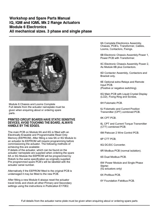
6A Complete Electronics Assembly, Chassis, PCB’s, Transformer, Cables, Looms, Contactors, Fixings.6B Electronic Chassis Assembly Power 1, Power PCB with Transformer.6C Electronic Chassis Assembly Power 2, As Module 6B plus Contactors.6D Contactor Assembly, Contactors and Bracket only.6E Optional extra Relays and Remote Input PCB.(Positive or negative switching).6G Main PCB with Liquid Crystal Display (LCD), Fixing Ring and Screws.6H Folomatic PCB.6J Folomatic and Current Position Transmitter (CPT) combined PCB.6K CPT PCB.6L CPT and Current Torque Transmitter (CTT) combined PCB.6M Pakscan 2 Wire Control PCB.6P CTT PCB.6Q DC/DC Converter.6R Modbus PCB (normal isolation).6S Dual Modbus PCB.6W Power Module and Single Phase Starter.(IQ actuators only)6X Profibus PCB.6Y Foundation Fieldbus PCB.Module 6 Chassis and Looms CompleteFull details from the actuator nameplate must be given when enquiring about or ordering spare parts.Full details from the actuator name plate must be given when enquiring about or ordering spare partsWorkshop and Spare Parts ManualIQ, IQM and IQML Mk 2 Range Actuators Module 6 ElectronicsAll mechanical sizes. 3 phase and single phasePRINTED CIRCUIT BOARDS HAVE STATIC SENSITIVE DEVICES, AVOID TOUCHING THE BOARD, ALWAYS HANDLE BY THE EDGES.The main PCB on Module 6A and 6G is fitted with an Electrically Erasable and Programmable Read OnlyMemory (EEPROM). After fitting a new 6A or 6G Module to an actuator its EEPROM will require programming before commissioning the actuator. The following methods of achieving this are available:If details of the actuator, which can be found on theactuator nameplate are supplied when ordering the spare 6A or 6G Module the EEPROM will be programmed by Rotork to the same specification as originally supplied. Pre programmed spare PCB’s will be labelled with the actuator serial number.Alternatively if the EEPROM fitted to the original PCB is undamaged it may be fitted to the new PCB.After fitting a new Module 6 always reset the actuator travel limits and check all other Primary and Secondary settings using the instructions in Publication E170E2.Pic 71Module 6A Electronics Assembly CompleteThe actuator may remain in situ on the valve if required when changing out this module.First isolate the actuator from all electrical supplies.Contactor Actuator Type SizeA.B.B V.B.C. 10,12,18, 20,25,35. CE15C 40,70 CE15E 90,91,95Disconnect all cables from the main PCB and any option cards fitted to it, note their positions for ease of reassembly.123 4 87652Remove Electronics CoverUsing a 6mm allen key (hex wrench) remove the four cap head screws securing the electronics cover, fit two of these screws into the threaded holes in the cover to jack it out.Care must be taken inremoving this cover as there is an electrical cable between it and the main PCB. Disconnect the plug and socket. Retain this cover and ‘O’ ring seal for refitting.Remove Main PCBRemove the main PCB together with its mounting ring from the four chassis legs. Note itsposition relative to the gearcase to ensure corrwect alignment when refitting replacement module.Move the four chassis legs outboard towards the casting. There is no need to remove them at this stage. Take note of cable routing so that it can be refitted in exactly the same position on reassembly.Remove Optional Relay Board, if fittedTake note of plug and socket positions so that the PCB can be refitted in the same position.Disconnect Power ModuleDisconnect all cables going onto the contactors taking note of their positions:-3 Phase Power marked 1-2-3. 3 Phase Motor marked U-V-W. Coils marked C1-C2-CC.Pic 71Pic 19Pic 81Pic 82Pic 83Pic 198Pic 226Pic 199Module 6A Electronics Assembly CompleteDisconnect plugs from sockets SK1-SK3 and SK10.This sketch gives the position ofall cable looms when powermodule is being secured to thegearcase, ensure that no cablesare trapped when tightening thefour screws. Tighten down to6.8nm (5lb/ft).9101112 161514133Remove Power Module Before removing power module take note of the cable routing so that it can be replicated when fitting replacement. Remove the four power module fixing screws.Click the four chassis legs into position. Reconnect motor cables marked U,V,W onto marked terminals on right hand contactor, connect 3 phase supply cables marked 2,3,1 to marked terminals on left hand contactor. Connect plug to socket 3 also plugs to SK1 and SK10 if used.Ensure that all heavy current power connections on the contactors are angled towards the centre of the chassis and Tyraped together.Refit Optional Relay PCB (if supplied)Position relay PCB in front of the contactors with sockets SK1 and SK4 to top left, reconnect plugs that are used. Position the four chassis legs so that the PCB is secured at its corners.Fit Replacement Power ModuleFirst check that the voltage tapping on the new item is set correctly, refer to tapping position on original item. Pic 201Pic 200Pic 201Pic 203Sketch 1Doc 584-1Pic 199Sketch 2Doc 537/01Pic 226Fitting Replacement Main PCBFirst check that replacement PCB is correctly labelled with the same serial number as that on the actuator name plate, if so then it was pre-programmed in the Rotork factory and can be fitted.If the replacement board was not ordered for a particular actuator or has been taken from another actuator then the EEPROM component on the main PCB must be transferred from the original board to its replacement.With the LCD (indication display) positioned as on original PCB, locate the four PCB clips onto the four chassis legs, these are a push and click fit.171819 232221204Using the correct tool asshown pull the EEPROM from its socket.When replacing the EEPROM ensure that the notches align on both EEPROM and socket, do not use exessive force when fitting as pins can get distorted.Reconnect PCBsReconnect all cables to main PCB and option card if fitted.Final Cable Routing CheckThe following four photographs will assist in the final check of cable routing and securing before fitting electronics cover.Top left view.Top right view.Lower left view.Pic 113Pic 114Pic 83Pic 196Pic 222Pic 223Pic 224View from above.Ensure that no cables will be damaged when the electronics cover is finally fitted.The battery is situated in its owncompartment located in thegearcase. Using an 8mm allenkey (hex wrench) remove theaccess plug.242526273029285Reconnect Electronics CoverEnsure that spigotted joint between cover and gearcase is clean, lightly greased and that the ‘O’ ring seal is serviceable. Reconnect the cable in cover onto the front of the main PCB. Refit cover locating the window over the display. Tighten down screws to 16.5nm (12lb/ft).Replace batteryWhilst the actuator is down for maintenance it is recommended that its battery be changed.The battery as fitted by Rotork is PP3 9 volt Ultralife Lithium cell, this exact type of battery MUST be fitted to all explosionproof units CENELEC/ FM/CSA.Disconnect the existing batteryand using the strap providedpull out of its plastic holder. Fitnew battery into strap and pushinto its holder, reconnect.Refit and tighten threaded plugafter lightly greasing thread andchecking sealing ‘O’ ring isserviceable.Recommission the actuatorusing Publication E170E2 andthe Rotork Infra Red SettingTool.Pic 225Pic 81Pic 19Pic 115Pic 25Pic 76Pic 28Module 6B Power PCB with transformer and chassis components (Re-using original contactor) 3 phase units onlyThe actuator may remain in situ on the valve if required when changing out this module.First isolate the actuator from all electrical supplies.Contactor Actuator Type SizeA.B.B V.B.C. 10,12,18, 20,25,35. CE15C 40,70 CE15E 90,91,95Disconnect all cables from the main PCB and any option cards fitted to it, note their positions for ease of reassembly. Retain this item.303233 34 383736356Remove Electronics CoverUsing a 6mm allen key (hex wrench) remove the four cap head screws securing the electronics cover, fit two of these screws into the threaded holes in the cover to jack it out.Care must be taken inremoving this cover as there is an electrical cable between it and the main PCB. Disconnect the plug and socket. Retain this cover and ‘O’ ring seal for refitting.Remove Main PCBRemove the main PCB together with its mounting ring from the four chassis legs. Note itsposition relative to the gearcase to ensure correct alignment when refitting.Move the four chassis legs outboard towards the casting,there is no need to removethem at this stage. Take note of cable routing so that it can be refitted in exactly the same position on reassembly. Retain this item.Remove Optional Relay Board if fittedTake note of plug and socket positions so that the PCB can be refitted in the same position. Retain this item.Disconnect Power ModuleDisconnect all cables going onto the contactors taking note of their positions:-3 phase power marked 1-2-3 3 phase motor marked U-V-W Coils marked C1-C2-CC.Pic 203Pic 19Pic 81Pic82Pic 83Pic 198Pic 226Pic 199Module 6B Power PCB with transformer and chassis components (Re-using original contactor) 3 phase units onlyDisconnect plugs from sockets SK1-SK3-SK10.Click the four chassis legs intoposition.39404142 464544437Remove Power Module Before removing power module take note of the cable routing so that it can be replicated when fitting replacement. Remove the four power module fixing screws.Remove Contactors from original Power Module and fit replacement unitUsing a 5mm allen key (hex wrench) remove the two screws securing the contactor mounting rail onto the plastic chassis. Remove the contactors complete with rail. Refit to new item. Tighten down rail fixing screws to3.4Nm (2.5lb/ft).Fit replacement Power ModuleFirst check that the voltage tapping on the new item is set correctly, refer to tapping position on original item.This sketch gives the position ofall cable looms when powermodule is being secured to thegearcase, ensure that no cablesare trapped when tightening thefour screws. Tighten down to6.8Nm (5lb/ft).Reconnect motor cables markedU,V,W onto marked terminals onright hand contactor. Connect 3phase supply cables marked2,3,1 to marked terminals on lefthand contactor. Connect plug tosocket 3 also plugs to SK1 andSK10 if used.Ensure that all heavy currentpower connections on thecontactors are angled towardsthe centre of the chassis andTyraped together.Pic 201Sketch 2Doc 537/01 Pic 200Pic 243Sketch 1Doc 548-1Pic 199 Pic 201Pic 203Module 6B Power PCB with transformer and chassis components (Re-using original contactor) 3 phase units onlyRefit optional Relay PCB (if supplied)Position relay PCB in front of the contactors with sockets SK1 and SK4 to top left,reconnect plugs that are used. Position the four chassis legs so that the PCB is secured at its corners.Top right view.47484950 545352518Reconnect Main PCBEnsure that all looms are connected to the main PCB and any option cards fitted to it.With the LCD (indication display) positioned as on original PCB, locate the four PCB clips onto the fourchassis legs, these are a push and click fit.Final Cable routing checkThe following four photographs will assist in the final check of cable routing and securing before fitting electronics cover.Top left view.Lower left view.View from above.Ensure that no cables will be damaged when the electronics cover is finally fitted.Reconnect Electronics CoverEnsure that spigotted jointbetween cover and gearcase is clean, lightly greased and that ‘O’ ring seal is serviceable. Reconnect the cable in cover onto the front of the main PCB.Pic 226Pic 197 Pic 196Pic 222Pic 223Pic 224Pic 225Pic 81Module 6B Power PCB with transformer and chassis components (Re-using original contactor) 3 phase units onlyRefit cover locating the window over the display. Tighten down screws to 16.5Nm (12lb/ft).Recommission the actuatorusing Rotork PublicationE170E2 and Rotork Infra RedSetting Tool.55565758599Replace BatteryWhilst the actuator is down for maintenance it is recommended that its battery be changed. The battery as fitted by Rotork isPP3 9volt Ultralife Lithium Cell. This exact type of battery MUST be fitted to all explosionproof units CENELEC/FM/CSA.The battery is situated in its own compartment located in the gearcase. Using an 8mm allen key (hex wrench) remove the access plug.Disconnect the existing battery and using the strap provided pull out of its plastic holder. Fit new battery into strap and push into its holder, reconnect. Refit and tighten threaded plug after lightly greasing and checking sealing ‘O’ ring is serviceable. Pic 19Pic 115Pic 25Pic 76Pic 28Module 6C Power PCB with contactors, transformer and chassis components 3 phase units onlyThe actuator may remain in situ on the valve if required when changing out this module.First isolate the actuator from all electrical supplies.Contactor Actuator Type SizeA.B.B V.B.C. 10,12,18, 20,25,35. CE15C 40,70 CE15E 90,91,95Disconnect all cables from the main PCB and any option cards fitted to it, note their positions for ease of reassembly. Retain this item.60616263 6766656410Remove Electronics CoverUsing a 6mm allen key (hex wrench) remove the four cap head screws securing the electronics cover, fit two of these screws into the threaded holes in the cover to jack it out.Care must be taken inremoving this cover as there is an electrical cable between it and the main PCB. Disconnect the plug and socket. Retain this cover and ‘O’ ring seal for refitting.Remove Main PCBRemove the main PCB together with its mounting ring from the four chassis legs. Note itsposition relative to the gearcase to ensure corrwect alignment when refitting replacement module.Move the four chassis legs outboard towards the casting,there is no need to removethem at this stage. Take note of cable routing so that it can be refitted in exactly the same position on reassembly. Retain this item.Remove optional Relay Board (if fitted)Take note of plug and socket positions so that the PCB can be refitted in the same position. Retain this item.Disconnect Power ModuleDisconnect all cables going onto the contactors taking note of their positions:-3 phase power marked 1-2-3 3 phase motor marked U-V-W Coils marked C1-C2-CC.Pic 203Pic 19Pic 81Pic 82Pic 83Pic 198Pic 226Pic 199Module 6C Power PCB with contactors, transformer and chassis components 3 phase units onlyDisconnect plugs from sockets SK1-SK3-SK10.This sketch gives the position ofall cable looms when powermodule is being secured to thegearcase, ensure that no cablesare trapped when tightening thefour screws. Tighten down to6.8Nm (5lb/ft).68697071 7574737211Remove Power Module Before removing power module take note of the cable routing so that it can be replicated when fitting replacement. Remove the four power module fixing screws.Fit replacement Power ModuleFirst check that the voltage tapping on the new item is set correctly, refer to tapping position on original item.Click the four chassis legs into position.Reconnect motor cablesmarked U,V,W onto markedterminals on right handcontactor. Connect 3 phasesupply cables marked 2,3,1 tomarked terminals on left handcontactor. Connect plug tosocket 3 also plugs to SK1 andSK10 if used.Ensure that all heavy currentpower connections on thecontactors are angled towardsthe centre of the chassis andTyraped together.Refit optional RelayPCB (if supplied)Position relay PCB in front ofthe contactors with sockets SK1and SK4 to top left, reconnectplugs that are used. Position thefour chassis legs so that thePCB is secured at its corners.Pic 201Pic 200Pic 201Pic 203Sketch 1Doc 548-1Pic 199Sketch 2Doc 537/01Pic 226Module 6C Power PCB with contactors, transformer and chassis components 3 phase units onlyReconnect Main PCBEnsure that all looms are connected to the main PCB and any option cards fitted to it.Lower left view.76777879 8382818012With the LCD (indication display) positioned as on original PCB, locate the four PCB clips onto the four chassis legs, these are a push and click fit.Final Cable routing checkThe following four photographs will assist in the final check of cable routing and securing before fitting electronics cover.Top left view.Top right view.View from above.Ensure that no cables will be damaged when the electronics cover is finally fitted.Reconnect Electronics CoverEnsure that spigotted jointbetween cover and gearcase is clean, lightly greased and that ‘O’ ring seal is serviceable. Reconnect the cable in cover onto the front of the main PCB.Refit cover locating the window over the display. Tighten down screws to 16.5Nm (12lb/ft).Pic 197 Pic 196Pic 222Pic 223Pic 224Pic 225Pic 81Pic 19Module 6C Power PCB with contactors, transformer and chassis components 3 phase units onlyReplace BatteryWhilst the actuator is down for maintenance it isrecommended that its battery be changed. The battery as fitted by Rotork isPP3 9volt Ultralife Lithium Cell. Thisexact type of battery MUST be fitted to all explosionproof units CENELEC/FM/CSA.8485868713The battery is situated in its own compartment located in the gearcase. Using an 8mm allen key (hex wrench) remove the access plug.Disconnect the existing battery and using the strap provided pull out of its plastic holder. Fit new battery into strap andpush into its holder, reconnect. Refit and tighten threaded plug after lightly greasing and checking sealing ‘O’ ring is serviceable.Recommission the actuator using Rotork PublicationE170E2 and Rotork Infra Red Setting Tool.Pic 115Pic 25Pic 76Pic 28Module 6D Contactor Assembly, Contactors and Brackets only, 3 phase units onlyThe actuator may remain in situ on the valve if required when changing out this module.First isolate the actuator from all electrical supplies.Contactor Actuator Type SizeA.B.B V.B.C. 10,12,18, 20,25,35. CE15C 40,70 CE15E 90,91,95Disconnect all cables from the main PCB and any option cards fitted to it, note their positions for ease of reassembly. Retain this item.888990 91 9594939214Remove Electronics CoverUsing a 6mm allen key (hex wrench) remove the four cap head screws securing the electronics cover, fit two of these screws into the threaded holes in the cover to jack it out.Care must be taken inremoving this cover as there is an electrical cable between it and the main PCB. Disconnect the plug and socket. Retain this cover and ‘O’ ring seal for refitting.Remove Main PCBRemove the main PCB together with its mounting ring from the four chassis legs. Note itsposition relative to the gearcase to ensure corrwect alignment when refitting replacement module.Move the four chassis legs outboard towards the casting,there is no need to removethem at this stage. Take note of cable routing so that it can be refitted in exactly the same position on reassembly.Remove Optional Relay Board (if fitted)Take note of plug and socket positions so that the PCB can be refitted in the same position.Remove and replace ContactorsDisconnect all cables going onto the contactors taking note of their positions:-3 phase power marked 1-2-3 3 phase motor marked U-V-W Coils marked C1-C2-CC.Pic 210Pic 19 Pic 81Pic 82Pic 83Pic 198Pic 226Pic 199Module 6D Contactor Assembly, Contactors and Brackets only, 3 phase units onlyUsing a 5mm allen key (hex wrench) remove the two screws securing the contactor mounting rail onto the plastic chassis. Remove the contactors complete with rail. Replace with new item, tighten down rail fixing screws to3.4Nm (2.5lb/ft).lRefit optional RelayPCB (if supplied)Position relay PCB in front ofthe contactors with sockets SK1and SK4 to top left, reconnectplugs that are used. Positionthe four chassis legs so that thePCB is secured at its corners.96979899 10310210110015Reconnect all cables to replacement contactors ensuring that connections are on the correct terminals and screws are tight.If the four chassis legs were removed earlier then click them back into position. Ensure that all heavy current power connections on the contactors are angled towards the centre of the chassis and Tyraped together.Reconnect Main PCBEnsure that all looms areconnected to the main PCB andany option cards fitted to it.With the LCD (indication display)positioned as on original PCB,locate the four PCB clips ontothe four chassis legs, these area push and click fit.Final Cable routingcheckThe following four photographswill assist in the final check ofcable routing and securingbefore fitting electronics coverTop left view.Pic 200Pic 199Pic 202Sketch 2Doc 537/01Pic 226Pic 197Pic 196Pic 222Module 6D Contactor Assembly, Contactors and Brackets only, 3 phase units onlyTop right view.Refit cover locating the window over the display. Tighten down screws to 16.5Nm (12lb/ft).104105106107 11111010910816Lower left view.View from above.Ensure that no cables will be damaged when the electronics cover is finally fitted.Reconnect Electronics CoverEnsure that spigotted jointbetween cover and gearcase is clean, lightly greased and that ‘O’ ring seal is serviceable. Reconnect the cable in cover onto the front of the main PCB.Replace BatteryWhilst the actuator is down for maintenance it is recommended that its battery be changed. The battery as fitted by Rotork isPP3 9volt Ultralife Lithium Cell. This exact type of battery MUST be fitted to allexplosionproof units CENELEC/FM/CSA.The battery is situated in its own compartment located in the gearcase. Using an 8mm allen key (hex wrench) remove the access plug.Disconnect the existing battery and using the strap provided pull out of its plastic holder. Fit new battery into strap and push into its holder, reconnect. Refit and tighten threaded plug after lightly greasing and checking sealing ‘O’ ring is serviceable.Pic 223Pic 224Pic 225 Pic 81Pic 19Pic 115Pic 25Pic 76Module 6D Contactor Assembly, Contactorsand Brackets only, 3 phase units onlyRecommission the actuatorusing Rotork PublicationE170E2 and Rotork Infra RedSetting Tool.Pic 2811217Module 6E Optional extra Relays and Remote Input PCB Positive or negative switchingThe actuator may remain in situ on the valve if required when changing out this module.First isolate the actuator from all electrical supplies.Disconnect all cables from the main PCB and any option cards fitted to it, note their positions for ease of reassembly.113 114115 116 12011911811718Remove Electronics CoverUsing a 6mm allen key (hex wrench) remove the four cap head screws securing the electronics cover, fit two of these screws into the threaded holes in the cover to jack it out.Care must be taken inremoving this cover as there is an electrical cable between it and the main PCB. Disconnect the plug and socket. Retain this cover and ‘O’ ring seal for refitting.Remove Main PCBRemove the main PCB together with its mounting ring from the four chassis legs. Note itsposition relative to the gearcase to ensure corrwect alignment when refitting replacement module.Move the four chassis legs outboard towards the casting,there is no need to removethem at this stage. Take note of cable routing so that it can be refitted in exactly the same position on reassembly.Removal of Optional Relay Board Module 6ETake note of plug and socket positions so that the PCB can be refitted in the same position.Replace Optional Relay PCB with new itemPosition relay PCB in front of the contactors with sockets SK1 and SK4 to top left, reconnect plugs that are used. Position the four chassis legs so that the PCB is secured at its corners.Pic 70Pic 19Pic 81Pic 82Pic 83Pic 198Pic 226Pic 226Positive or negative switchingReconnect Main PCBEnsure that all looms are connected to the main PCB and any option cards fitted to it.Lower left view.121122123124 12812712612519With the LCD (indication display) positioned as on original PCB, locate the four PCB clips onto the four chassis legs, these are a push and click fit.Final Cable routing checkThe following four photographs will assist in the final check of cable routing and securing before fitting electronics cover.Top left view.Top right viewView from above.Reconnect Electronics CoverEnsure that spigotted jointbetween cover and gearcase is clean, lightly greased and that the ‘O’ ring seal is serviceable. Reconnect the cable in cover onto the front of the main PCB.Refit cover locating the window over the display. Tighten down screws to 16.5Nm (12lb/ft).Pic 197Pic 196Pic 222Pic 223Pic 224Pic 225Pic 81Pic 19Positive or negative switchingReplace BatteryWhilst the actuator is down for maintenance it isrecommended that its battery be changed. The battery as fitted by Rotork isPP3 9volt Ultralife Lithium Cell. Thisexact type of battery MUST be fitted to all explosionproof units CENELEC/FM/CSA.12913013113220The battery is situated in its own compartment located in the gearcase. Using an 8mm allen key (hex wrench) remove the access plug.Disconnect the existing battery and using the strap provided pull out of its plastic holder. Fit new battery into strap andpush into its holder, reconnect. Refit and tighten threaded plug after lightly greasing and checking sealing ‘O’ ring is serviceable.Recommission the actuator using Rotork PublicationE170E2 and Rotork Infra Red Setting Tool.Pic 115Pic 25Pic 76Pic 28Module 6G Main PCB with Liquid Crystal Display (LCD) and fixing ringThe actuator may remain in situ on the valve if required when changing out this module.First isolate the actuator from all electrical supplies.Disconnect all cables from themain PCB and any option cardsfitted to it, note their positionsfor ease of reassembly.133134135136 13913813721Remove Electronics CoverUsing a 6mm allen key (hex wrench) remove the four cap head screws securing the electronics cover, fit two of these screws into the threaded holes in the cover to jack it out. Care must be taken in removing this cover as there is an electrical cable between it and the main PCB. Disconnect the plug and socket. Retainthis cover and ‘O’ ring seal for refitting.Remove Main PCB Remove the main PCB together with its mounting ring from the four chassis legs. Note its position relative to the gearcase to ensure corrwect alignment when refitting replacement module.Remove Option Card iffittedDisconnect all cables from theoption card noting theirpositions, remove the fixingscrews securing option card tomain PCB and unplug card.Transfer this option card ontothe replacement PCB.Fitting replacementMain PCBFirst check that replacementPCB is correctly labelled withthe same serial number as thaton the actuator name plate, if sothen it was pre-programmed inthe Rotork factory and can befitted.If the replacement board wasnot ordered for a particularactuator or has been taken fromanother actuator then theEEPROM component on themain PCB must be transferredfrom the original board to itsreplacement.Using the correct tool as shownpull the EEPROM from itssocket.Pic 65Pic 19Pic 81Pic 82Pic 83Pic 112Pic 113。

动力蓄电池拆解信息表汽车企业名称金华青年汽车制造有限公司注册地址浙江省金华市婺城区工业园区M-09地块车辆类型乘用车及客车车辆型号JNP6123BEV3N、JNP6123BEV3ND联系人黄红良职务主任联系电话E-mail动力蓄电池拆解信息信息分类信息要求信息说明L240C01动力蓄电池基本信息PD 动力蓄电池包规格/型号011动力蓄电池制造商宁德时代新能源科技股份有限公司电池类型磷酸铁锂尺寸大小L240C01电箱:1060.00*630.00*240.00(mm)单体外形方形额定容量240.00Ah标称电压115.2V电池包质量212.00kg正极材料磷酸铁锂负极材料石墨隔膜类型高分子材料电解液类型液态所含模块的数量NA所含单体的数量36模块串并联方式NA单体串并联方式1P36S其他信息无L240B01动力蓄电池基本信息PD 动力蓄电池包规格/型号010动力蓄电池制造商宁德时代新能源科技股份有限公司电池类型磷酸铁锂尺寸大小L240B01电箱:820.00*630.00*240.00(mm)单体外形方形额定容量240.00Ah标称电压76.8 V电池包质量147.00kg正极材料磷酸铁锂负极材料石墨隔膜类型高分子材料电解液类型液态所含模块的数量NA所含单体的数量24模块串并联方式NA单体串并联方式1P24S其他信息无动力蓄电池拆解总体要求MSD 拆解条件MSD拆解企业应具备资质,如经营范围包括废旧电池类的经营许可证、国家规定的相关目录企业等;对拆解人员需要有相关职业资格证书等。
电池包绝缘阻值>100Ω/V,箱体内温度<65℃(红外测温仪),无热失控现象(冒烟、起火等)。
装备要求MSD起重设备、放电设备、加热设备(烘烤炉)、红外测温仪、相关扭力扳手及套筒,劳保安全用品等场地要求足够操作空间,无易燃易爆物品,周围有充足的灭火、防爆等安全设施。
其他拆解产物分类要求、有毒有害物质处理要求,操作人员有电工证等上岗证明、有防护设备。


刀片锂电池带外壳的拆卸方法解释说明以及概述1. 引言1.1 概述本篇长文旨在介绍刀片锂电池带外壳的拆卸方法,以便读者了解如何正确高效地进行该操作。
刀片锂电池是一种常见的电池类型,在许多电子设备中被广泛应用,但其外壳的拆卸可能会存在一定难度。
因此,本文将详细介绍拆卸的原理、所需工具和具体步骤。
1.2 文章结构文章将分为四个主要部分。
首先是引言部分,概述文章的目的和结构。
第二部分将深入介绍刀片锂电池带外壳的拆卸方法,包括原理介绍、工具准备和拆卸步骤。
接下来,第三部分将对为何需要拆卸刀片锂电池外壳进行解释说明,并探讨外壳对电池性能的影响以及在选择拆卸方法时需要考虑的因素。
最后,在第四部分中总结拆卸方法和要点,并展望未来刀片锂电池拆卸方法发展与建议。
1.3 目的本文的目标旨在提供一个清晰详尽的指南,帮助读者了解刀片锂电池带外壳的拆卸方法。
通过本文,读者将能够理解拆卸原理、熟悉所需工具和掌握正确的操作步骤。
此外,本文还将解释为何需要进行刀片锂电池外壳的拆卸,以及外壳对电池性能的影响和在选择拆卸方法时应注意的因素。
最终,希望读者能够掌握对刀片锂电池带外壳进行拆卸的技能,并且在实际操作中能够准确、安全地完成该任务。
2. 刀片锂电池带外壳的拆卸方法2.1 原理介绍:刀片锂电池作为一种常见的电池类型,其外壳通常由塑料或金属材料制成。
在某些情况下,我们需要拆卸刀片锂电池的外壳,例如进行维修、更换损坏部件或对电池进行重组。
拆卸刀片锂电池的外壳是一个技术活,需要正确的操作步骤和正确使用的工具。
2.2 工具准备:在开始拆卸刀片锂电池之前,我们需要准备以下工具:- 一把小型螺丝刀:用于拧紧和解开外壳上的螺丝。
- 扁嘴钳:用于握住和稳定电池以防止滑动。
- 塑料手柄棒:用于轻轻撬开电池外壳,并避免损坏内部组件。
- 夹子或夹子台:用于固定电池以方便进行维修和更换。
2.3 拆卸步骤:以下是一般情况下拆卸带外壳的刀片锂电池的步骤:步骤1: 安全措施在拆卸刀片锂电池之前,确保你已经断开电源并处于安全的工作环境中。