一种噪声优化的900MHz低噪声放大器设计
- 格式:pdf
- 大小:809.42 KB
- 文档页数:4
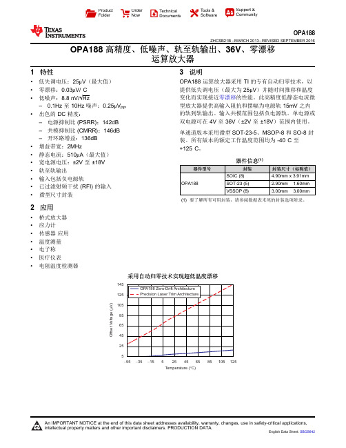
145125105856545255O f f s e t V o l t a g e (V )m -55-15525125Temperature (C)°-35456585105ProductFolder Order NowTechnical Documents Tools &SoftwareSupport &CommunityOPA188ZHCSB21B –MARCH 2013–REVISED SEPTEMBER 2016OPA188高精度、低噪声、轨至轨输出、36V 、零漂移运算放大器1特性•低失调电压:25μV (最大值)•零漂移:0.03μV/°C •低噪声:8.8nV/√Hz–0.1Hz 至10Hz 噪声:0.25μV PP •出色的DC 精度:–电源抑制比(PSRR);142dB –共模抑制比(CMRR):146dB –开环路增益:136dB •增益带宽:2MHz•静态电流:510μA (最大值)•宽电源电压:±2V 至±18V •轨至轨输出•输入包括负电源轨•已过滤射频干扰(RFI)的输入•微型尺寸封装2应用•桥式放大器•应力计•传感器应用•温度测量•电子称•医疗仪表•电阻温度检测器3说明OPA188运算放大器采用TI 的专有自动归零技术,以提供低失调电压(最大为25μV )并随时间推移和温度变化而实现接近零漂移的性能。
此高精度低静态电流微型放大器提供高输入阻抗和摆幅为电源轨15mV 之内的轨到轨输出。
输入共模范围包括负电源轨。
单电源或双电源可在4V 至36V (±2V 至±18V )范围内使用。
单通道版本采用微型SOT-23-5、MSOP-8和SO-8封装。
所有版本的额定工作温度范围均为-40°C 至+125°C 。
器件信息(1)器件型号封装封装尺寸(标称值)OPA188SOIC (8) 4.90mm x 3.91mm SOT-23(5) 2.90mm ×1.60mm VSSOP (8)3.00mm ×3.00mm(1)要了解所有可用封装,请参阅数据表末尾的封装选项附录。
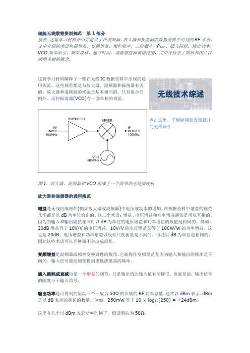
理解无线数据资料规范—第1部分摘要:这篇学习材料介绍并定义了在混频器、放大器和振荡器的数据资料中用到的RF术语。
文中介绍的术语包括增益、变频增益、相位噪声、三阶截点、P1dB、插入损耗、输出功率、VCO频率牵引、频率漂移、建立时间、调谐增益和调谐范围,文中还给出了图形和图片以阐明关键的概念。
这篇学习材料解释了一些在无线IC数据资料中出现的通用规范。
这些规范都是与放大器、混频器和振荡器有关的。
放大器和混频器的规范是基本相同的,只有很少的例外。
压控振荡器(VCO)有一套单独的规范。
点击这里,了解射频收发器设计的无线器件图1. 放大器、混频器和VCO组成了一个简单的无线接收机放大器和混频器的通用规范增益是无线组成部件(例如放大器或混频器)中电压或功率的增加。
在数据资料中增益的规范几乎都是以dB为单位给出的。
这三个术语:增益、电压增益和功率增益通常是可以互换的。
因为当输入和输出阻抗相同时以dB为单位的电压增益和功率增益的数值是相同的。
例如,20dB增益等于10V/V的电压增益,10V/V的电压增益又等于100W/W的功率增益,这也是20dB。
电压增益和功率增益以线性尺度衡量是不同的,但是以dB为单位是相同的,因此这些术语可以互换而不会造成混乱。
变频增益是混频器或频率变换器件的规范。
它被称作变频增益是因为输入和输出的频率是不同的。
输入信号被混频变换到更低或更高的频率。
插入损耗或衰减也是一个增益的规范,只是输出值比输入值有所降低。
也就是说,输出信号的幅度小于输入信号。
输出功率是可得到的驱动一个一般为50Ω的负载的RF功率总量。
通常以dBm表示。
dBm 是以dB表示的毫瓦的数量。
例如,250mW等于10 × log10(250) = +24dBm。
这里有几个以dBm表示功率的例子,假设阻抗为50Ω:+30dBm = 1W = 7.1V RMS0dBm = 1mW = 0.225V RMS-100dBm = 0.1pW = 2.25µV RMS1dB压缩点(P1dB)是输出功率的性能参数。

手机的构造及其工作原理手机包括四个系统:音频逻辑系统:完成音频数字信号的处理以及手机音频控制各部分的逻辑。
射频系统:完成信号的接收和传输,是手机与基站之间信息交换的桥梁。
人机接口系统:实现人机之间的沟通交流,供用户查看运行结果。
电源系统:手机及其所需的各种电压来源于由手机电池,手机内部的电池电压需转换为多种不同的电压,以供手机的不同部件使用。
1、音频逻辑系统逻辑控制可分为音频逻辑和音频信号处理两部分。
它是完整的数字信号处理和手机工作的管理和控制。
1.1逻辑电路部分手机逻辑电路主要由CPU和存储器组成。
在手机程序存储器中,存储主程序、主存储芯片手机机身码(俗称串号)和一些检测程序、如电池检测、电压显示检测程序等的主要工作是字体(版本)。
CPU与存储器组通过总线和控制线连接。
所谓总线,是由4到20根功能性质一样的数据传输线组成。
所谓控制线,是指获得各项操作指令的CPU存储器通道,例如芯片选择信号、复位信号、监视信号和读写信号等。
在存储器的支持下,CPU才能发挥其复杂多样的功能。
如果没有存储器或其中某些部分出错,手机就会出现软件故障。
CPU 对音频部分和射频部分的控制处理也是通过控制线完成的,这些控制信号一般包括静音(MUTE)、显示屏使能(LCDEN)、发光控制(LIGHT)、充电控制(CHARGE)、接收使能(RXON/RXEN)、发送使能(TXON/TXEN)、频率合成器使能(SYNEN)、频率合成器时钟(SYNCLK)等。
这些从CPU部分、射频部分和电源部分发出的控制信号扩展到音频信号,以完成手机复杂的控制工作。
所有工作电路都需要设置时间,即前面所说的13MHz。
部分机型为26MHz或19.5MHz,使用前需在机内进行分频。
还有一块实时时钟晶体,其特殊频率为32.768kHz。
主要功能为,为显示屏提供正确的时间显示及让手机处于睡眠状态。
早期机型无该晶体,所以没有时间显示和睡眠功能。
1.2音频电路1.2.1接收音频处理电路接收机通过解调得到的接收机基带信号被送到逻辑音频电路进行处理。

TP2411/TP2412/TP2414描述:TP2411,TP2412和TP2414是低成本,单路,双路和四路轨到轨输出,单电源放大器,具有低失调和输入电压,低电流噪声和宽信号带宽。
低失调,低噪声,非常低的输入偏置电流和高速的结合使这些放大器可用于各种应用。
滤波器,积分器,光电二极管放大器和高阻抗传感器都受益于这种功能组合。
音频和其他交流应用受益于这些设备的宽带宽和低失真。
这些放大器的应用包括功率放大器(PA)控制,激光二极管控制环路,便携式和环路供电的仪器,便携式设备的音频放大以及ASIC输入和输出放大器。
TP2411/TP2412/TP2414特点:增益带宽积:10 MHz低噪声:8.2 nV /√Hz(f = 1kHz)摆率:7 V /μs失调电压:1 mV(最大)EMIRR IN +:88 dB(在2.4GHz下)低THD + N:0.0005%电源范围:2.2 V至5.5 V电源电流:1.4 mA / ch低输入偏置电流:0.3pA(典型值)轨到轨I / O高输出电流:70 mA(1.0V压降)–40°C至125°C的工作范围Features Description增益带宽积:10 MHz低噪声:8.2 nV /√Hz(f = 1kHz)摆率:7 V /μs失调电压:1 mV(最大) EMIRR IN +:88 dB(在2.4GHz下)TP2411,TP2412和TP2414是低成本,单,双和四轨至轨输出,单电源放大器,具有低失调和输入电压,低电流噪声和宽信号带宽。
低失调,低噪声,非常低的输入偏置电流和高速的结合使这些放大器可用于多种应用。
滤波器,积分器,光电二极管放大器和高阻抗传感器都受益于这种功能组合。
音频和交流应用受益于这些设备的宽带宽和低失真。
低THD + N:0.0005%电源范围:2.2 V至5.5 V 电源电流:1.4 mA / ch 低输入偏置电流:0.3pA (典型值)轨到轨I / OTP2411,TP2412和TP2414是低成本,单,双和四轨至轨输出,单电源放大器,具有低失调和输入电压,低电流噪声和宽信号带宽。
室内分布系统简介室内分布系统是将信号源信号均匀地分布在建筑物内部的每个地方,以实现室内覆盖。
这种方式可以彻底解决室内覆盖的问题,但设计较复杂,而且采用的结构不同成本亦不同。
按传输介质分为:电分布系统和光纤分布系统耦合器:是一种非等功率分配的功率分配器件信源:宏蜂窝基站(含BBU+RRU)、微蜂窝基站、直放站等。
计算方法:方向性=隔离度-耦合度(例如6dB的隔离度是38dB,耦合度实测是.5dB,则方向性=隔离度-耦合度=38-.5=35dB。
馈线:测量主机上行噪声电平P NO,根据RX,基站发射功率P C(CDMA:33dBm,GSM:40dBm),基站天线增益一般取14dBi,因从基站到施主天线之间的上、下行空间损耗L P基本相同,即L P=(P C+14)-RX,由此计算到达基站端的噪声L NT=P NO-L P,为使得到达基站端的噪声不高于-120dBm。
干扰基站的原因:上行输出噪声干扰,.放大器线性不好,下行交调产物串入上行干扰基站,收发天线隔离不够,系统自激GSM中跳频可分为基带跳频和射频跳频两种。
其采取跳频的原因是因为它可以起到(频率分集)和(抗干扰)的作用●对于WCDMA系统,话音业务的比特速率为12Kbps,则其处理增益为。
(25dB)●WCDMA采用的多址接入方式为。
(DS-CDMA)●WCDMA系统是(干扰)受限系统●WCDMA系统中,下行扩频因子的取值范围为__4-512___。
●WCDMA下行方向共有多少个主扰码?(,512)●WCDMA系统,下行扰码共有8192个,其中可以分为_512___个的扰码集,每个扰码集中包括1个主扰码和_15___个的从扰码;这些扰码集又可以分成_64___个扰码组,每个扰码组中有_8___个主扰码。
●重发天线与施主天线间的隔离度:15dB●光纤直放站的下行输入值范围为:(10dBm~-10dBm)●光纤直放站的增益可调范围是(0dB~26dB)●干线放大器的增益可调范围是:(0dB~22dB)●光纤直放站的光收功率范围为:(0dBm~-10dBm)●无线直放站的下行输入值范围是:(-45dBm~-60dBm)●在光纤直放站系统中,上下行增益分别是由:(上行低噪放控制、下行功放控制)●干线放大器的下行输入值范围是:(5dBm~-10dBm)●在开通CDMA无线直放站时,基站接收到的上行底噪要求小于(-120dBm)●WCDMA系统的空中接口带宽为(5MHz)直放站的带内平坦度(峰峰值)小于3db、100mW等于20dbm●直放站三阶互调指标的测试,在2f1-f2处测量和在2f2-f1处测量●1/2普通馈线100米线损为:7dB●在GSM900工作频段中,1/2的馈线每米损耗值为(0.07dbm) 0.04●1/2“普通阻燃馈线的静态弯曲半径为70mm。
TP5591、TP5592、TP5594放大器是单,双和四斩波稳定的零漂移运算放大器,针对1.8V至5.5V或±0.9V至±2.75V的单电源或双电源供电进行了优化。
TP559x运算放大器具有非常低的输入失调电压和低噪声,且1 / f噪声角低至0.1Hz。
TP559x放大器设计为具有低失调电压和失调温度漂移,宽增益带宽以及轨至轨输入和输出摆幅,同时将功耗降至最低。
TP559x运算放大器可提供低失调电压(最大20μV)和接近具有出色的CMRR和PSRR,可在时间和温度范围内实现零漂移.TP5591(单个版本)采用SC70-5,SOT23-5和SO-8封装。
TP5592(双版本)以MSOP-8,SO-8封装提供。
TP5594(四版本)以TSSOP-14和SO-14封装提供。
所有版本的额定工作温度范围均为-40°C至125°C。
特点:低失调电压:20μV(最大值)零漂:0.01 µV /°C超低噪声:-输入噪声电压:1 kHz时为17 nV /√Hz-0.1Hz至10Hz噪声电压:370 nVPP-1 / f噪声角低至0.1Hz3.3 MHz带宽,2.5 V /μs压摆率低电源电流:每个放大器470μA单电源工作电压低至+ 1.8V低输入偏置电流:60 pA高增益,127 dB高CMRR和PSRR过载恢复时间:35 µs轨到轨输入和输出摆幅–40°C至125°C的工作范围应用:医疗仪器温度测量精密电流感应精密低漂移,低频ADC驱动器过程控制系统精密基准电压缓冲器Pin Configuration (Top View)Order InformationModel Name Order Number Package Transport Media, QuantityMarking InformationTP5591-TR SOT23-5 Tape and Reel, 3,000 E91T TP5591 TP5591-CR SC70-5 Tape and Reel, 3,000 91C TP5591-SR SOIC-8 Tape and Reel, 4,000 TP5591TP5591U TP5591U-CR SC70-5 Tape and Reel, 3,000 91V TP5591U-TR SOT23-5 Tape and Reel, 3,000 E91UTP5592 TP5592-SR SOIC-8 Tape and Reel, 4,000 TP5592 TP5592-VR MSOP-8 Tape and Reel, 3,000 TP5592TP5594 TP5594-SR SOIC-14 Tape and Reel, 2,500 TP5594 TP5594-TR TSSOP-14 Tape and Reel, 3,000 TP5594Absolute Maximum RatingsNote 1Supply Voltage: .....................................................6V Current at Supply Pins……………............... ±50mAInput Voltage: ....................... ……V–– 0.1 to V+ + 0.1 Operating Temperature Range.......–40°C to 125°CInput Current: +IN, –IN Note2........................... ±20mA Maximum Junction Temperature................... 150°C Output Current: OUT...................................... ±60mA Storage Temperature Range.......... –65°C to 150°COutput Short-Circuit Duration Note3…....... Indefinite Lead Temperature (Soldering, 10 sec) ......... 260°CNote 1: Stresses beyond those listed under Absolute Maximum Ratings may cause permanent damage to the device. Exposure toany Absolute Maximum Rating condition for extended periods may affect device reliability and lifetime.Note 2: The inputs are protected by ESD protection diodes to each power supply. If the input extends more than 500mV beyond the power supply, the input current should be limited to less than 10mA.Note 3: A heat sink may be required to keep the junction temperature below the absolute maximum. This depends on the power supply voltage and how many amplifiers are shorted. Thermal resistance varies with the amount of PC board metal connected tothe package. The specified values are for short traces connected to the leads.ESD, Electrostatic Discharge ProtectionSymbol Parameter Condition Minimum Level Unit HBM Human Body Model ESD ANSI/ESDA/JEDEC JS-001 7 kV CDM Charged Device Model ESD ANSI/ESDA/JEDEC JS-002 2Electrical CharacteristicsAt T A = 27°C, V S = 5V, R L = 10kΩ, V CM = V DD/2, unless otherwise noted.SYMBOL PARAMETER CONDITIONS MIN TYP MAX UNITS V S Supply voltage range 1.8 5.5 VI Q Quiescent current per amplifier TP5591 1200 1400 μA TP5592/4 550 950 μAV OS Input offset voltage V CM = 0.05V to 4.95V ±5 ±20 μV V S = 1.8V, V CM = 0.9V ±5 ±20 μVdV OS/dT vs. Temperature 0.01 μV/°C PSRR vs power supply Vs = 3V to 5V 95 130 dBV n Input voltage noise, f=0.01Hz to 1Hz 0.1 μV pp Input voltage noise, f=0.1Hz to 10Hz 0.37 μV ppe n Input voltage noise density, f=1kHz 17 nV/√HzC IN Input capacitor differential 3 pF Input capacitor common-mode 2 pFI B Input current ±60 ±200 pA Over temperature ±800 pAI OS Input offset current ±100 ±400 pAV CM Common-mode voltage range (V-)-0.1 (V+)+0.1 V CMRR Common-mode rejection ratio V CM = 0.5V to 4.5V 110 127 dB Output voltage swing from rail R L=10kΩ 5 25 mV I SC Short-circuit current ±60 mA GBWP Unity gain bandwidth C L=100pF 3.3 MHz SR Slew rate G=+1, C L=100pF 2.5 V/μs t OR Overload recovery time G=-10 35 μs t S Settling time to 0.01% C L=100pF 20 μsA VOL Open-loop voltage gain (V-)+100mV<V O<(V+)-100mV,R L = 100kΩ100 130 dB SOT23-5 200MSOP-8 210θJA Thermal resistance junction toambientSO-8 158SC70-5 250SO-14 83°C/WTSSOP-14 100Typical Performance CharacteristicsQuiesent C urrent v s TemperatureVoltage Noise Spectral Density vs Frequency 100010090080070060010500400300200100-50 -25 0 25 50 75 100 125 150 10.01 0.1 1 10 100 1k 10kTemperature(°C)Frequency (Hz)CMRR vs FREQUENCY OPEN-LOOPGAIN vs FREQUENCY120 100 140100908012080 70 1006060508040406020 30 40201020-20 010 100 1k 10k 100k 1M 10MFrequency(Hz) 1 10 100 1k 10k 100k 1MFrequency(Hz) Small-Scale Step Response Positive Over-Voltage RecoveryG=+1R L=10KΩInputOutputTime (5μs/div) Time (50μs/div)Negative Over-Voltage Recovery Large-Scale Step ResponseG=+1R L=10KΩInputOutputTime (50μs/div)Time (10μs/div)Offset Voltage Distribution18161412108642Offset Voltage (μV)Typical ApplicationsSingle Supply, High Gain Amplifier, A V = 10,000 V/V-TP5591+Thermistor Measurement-TP5591+Pin Functions-IN:放大器的反相输入。
微蜂窝(Microcell)发射功率小(一般最大2兆/载波)天线位置底(解决微小区,微微小区的覆盖)安装简便(室内室外壁挂式安装)易于频率规划(微小区不易产生频率干扰)它是解决移动通信在高话务量区的最佳选择,广泛用于机场,车站。
交易会,宾馆,地下商场的覆盖。
技术指标:频率上行890-915Mhz下行935-960Mhz载波带宽200K hz信道数8个全速率信道/载波调制方式GMSK最小频率间隔400 K hz最大发射功率33dbm/载波接收灵敏度-107 dbm室内覆盖应考虑的因素:隔墙的阻挡(5-20db)楼房的阻挡(20db以上)家具等其他障碍物的阻挡(2-15db)多路径衰减高层建筑物(20)或以上“孤岛效应”—无信号覆盖“乒乓效应”—信号强度理想,通话困难。
解决室内覆盖的基本方法:通过天馈系统的分布,将信号送达建筑物内部的各个区域,以得到尽善尽美的信号覆盖效果。
天馈分布系统:采用8D-SFAE软馈线,便于室内布线。
专为室内覆盖设计的吸顶式和壁挂式天线。
配以功分/合路器,将微蜂窝的信号均匀的分布到各楼层。
天馈分布系统的相关材料:日本关西8D—SFAE软馈线,900MHZ频段衰减11.3DB/100米二功分/合路器衰减3.5 DB三功分/合路器衰减5 DB四功分/合路器衰减7 DB壁挂式和吸顶式增益2—4 DB天馈延伸系统;天线分布适合于一个微蜂窝覆盖8层楼左右,建筑面积约5000平方米。
若更大的建筑,一般无源天馈系统很难满足覆盖需要。
对于较大型的建筑覆盖,需增加放大器,以补偿信号在传输过程中的衰耗。
延伸放大系统.延伸放大器:增益10—20db可调输出功率:18dbm具有ALC(自动电平控制)采用DC15V芯线馈电供电器:将AC220交流电变换成15V直流电,经馈线送至延伸放大器。
光纤信号分布系统:同轴电缆——布线困难,损耗小,不适于长距离传输信号。
对于大型写字楼,高层酒店,地下隧道的覆盖需使用布线方便损耗小的传输方式——光纤传输距离远,(>3公里),使用非金属光纤,布线方便。
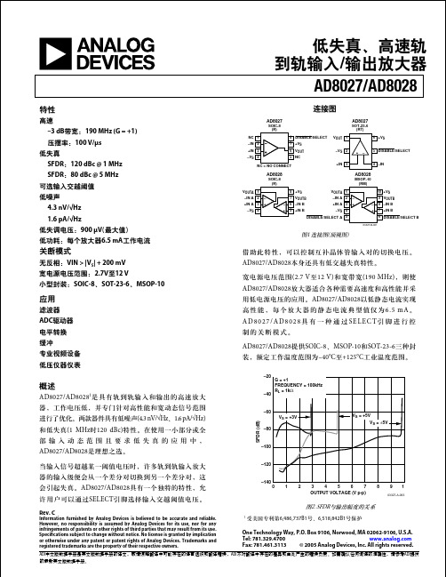
LTC6087CMS8#PBF160878fdFor more information /LTC6087FEATURESAPPLICATIONSDESCRIPTIONRail-to-Rail CMOS AmplifiersThe L TC ®6087/LTC6088 are dual/quad, low noise, low offset, rail-to-rail input/output, unity-gain stable CMOS operational amplifiers that feature 1pA of input bias current. A 14MHz gain bandwidth and 7.2V/µs slew rate, combined with low noise (10nV/√Hz ) and a low 0.75mV offset, make the LTC6087/LTC6088 useful in a variety of applications. The 1.05mA supply current and the shutdown mode are ideal for signal processing applications which demand performance with minimal power.The LTC6087/LTC6088 has an output stage which swings within 30mV of either supply rail to maximize signal dy-namic range in low supply applications. The input common mode range includes the entire supply voltage. These op amps are specified on power supply voltages of 3V and 5V from –40°C to 125°C.The dual amplifier LTC6087 is available in 8-lead MSOP and 10-lead DFN packages. The quad amplifier LTC6088 is available in 16-lead SSOP and DFN packages.Single Supply Shock/Vibration Sensor AmplifiernLow Offset Voltage: 750µV Maximum n Low Offset Drift: 5µV/°C Maximum n Input Bias Current: 1pA (Typical at 25°C) 15pA (Typical at 85°C)n Rail-to-Rail Inputs and Outputs n Gain Bandwidth Product: 14MHz n CMRR: 70dB Minimum n PSRR: 93dB Minimumn Input Noise Voltage Density: 12nV/√Hz n Supply Current: 1.05mA per Amp n Shutdown Current: 2.3µA per Amp n 2.7V to 5.5V Operation Voltagen Available in 8-Lead MSOP and 10-Lead DFN Packages (LTC6087), 16-Lead SSOP and DFN Packages (LTC6088)nPortable Test Equipment n Medical Equipment n Audion Data AcquisitionnHigh Impedance T ransducer AmplifierLTC6087 Input Bias Currentvs TemperatureTYPICAL APPLICATIONMURATA SHOCKOUT = 2.7V TO 5.5VTEMPERATURE (°C)I N P U T B I A S C U R R E N T (p A )10100100060878 TA01b1L , L T, L TC, L TM, Linear Technology and the Linear logo are registered trademarks of Analog Devices, Inc. All other trademarks are the property of their respective owners.LTC6087/LTC6088260878fdFor more information /LTC6087ABSOLUTE MAXIMUM RATINGSTotal Supply Voltage (V + to V –) ...................................6V Input Voltage ......................................................V – to V +Input Current ........................................................±10mA SHDNA /SHDNB Voltage .....................................V – to V +Output Short-Circuit Duration (Note 2) ............Indefinite Operating Temperature Range (Note 3)LTC6087C/LTC6088C ..........................–40°C to 85°C LTC6087H/LTC6088H ........................–40°C to 125°C(Note 1)Specified Temperature Range (Note 4)LTC6087C/LTC6088C ..............................0°C to 70°C LTC6087H/LTC6088H ........................–40°C to 125°C Junction Temperature ...........................................150°C Storage Temperature Range ..................–65°C to 150°C Lead Temperature (Soldering, 10 sec)MS8, GN16 Only ...............................................300°CPIN CONFIGURATIONLTC6087/LTC6088360878fdFor more information /LTC6087ORDER INFORMATIONThe l denotes the specifications which apply over the full specifiedtemperature range, otherwise specifications are at T A = 25°C. Test conditions are V + = 3V, V – = 0V, V CM = 0.5V unless otherwise noted.SYMBOL PARAMETER CONDITIONSC SUFFIXH SUFFIXUNITS MIN TYPMAXMINTYPMAXV OSOffset Voltage (Note 5)LTC6087MS8, LTC6088GN LTC6087DD, LTC6088DHC LTC6087MS8, LTC6088GN LTC6087DD, LTC6088DHC l l ±330 ±330±750 ±1100±900 ±1350±330 ±330±750 ±1100±1100 ±1600µVµV µV µV ∆V OS /∆T Input Offset Voltage Drift (Note 6)LTC6087MS8, LTC6088GN LTC6087DD, LTC6088DHC l l ±2 ±2±5 ±5±2 ±2±5 ±5µV/°C µV/°C I B Input Bias Current (Notes 5, 7)Guaranteed by 5V Test l 1 401 500pA pA I OS Input Offset Current (Notes 5, 7)Guaranteed by 5V Test l0.5 300.5 150pA pA e nInput Noise Voltage Density f = 1kHz f = 10kHz 12 1012 10nV/√Hz nV/√Hz Input Noise Voltage0.1Hz to 10Hz 2.5 2.5µV P-P i n Input Noise Current Density (Note 8) f = 1Hz0.560.56fA/√Hz Input Common Mode Range l V –V +V –V +V C IN Input Capacitance Differential Mode Common Modef = 100kHz2.7 4.22.7 4.2pF pF CMRR Common Mode Rejection Ratio 0V ≤ V CM ≤ 3V l 64 638064 6180dB dB PSRR Power Supply Rejection Ratio V S = 2.7V to 5.5V l 93 9011593 85115dB dB V OUTOutput Voltage, High (Referred to V +)No LoadI SOURCE = 1mA I SOURCE = 5mA l l l 5 25 12015 50 210 5 25 12020 50 230mV mV mV Output Voltage, Low (Referred to V –)No Load I SINK = 1mA I SINK = 5mAl l l5 25 12025 50 2105 25 12030 60 240mV mV mVLEAD FREE FINISH TAPE AND REEL PART MARKING*PACKAGE DESCRIPTIONTEMPERATURE RANGE LTC6087CDD#PBF LTC6087CDD#TRPBF LCTX 10-Lead (3mm × 3mm) Plastic DFN –40°C to 85°C LTC6087HDD#PBF LTC6087HDD#TRPBF LCTX 10-Lead (3mm × 3mm) Plastic DFN –40°C to 125°C LTC6087CMS8#PBF LTC6087CMS8#TRPBF L TCTY 8-Lead Plastic MSOP –40°C to 85°C LTC6087HMS8#PBF LTC6087HMS8#TRPBF L TCTY 8-Lead Plastic MSOP–40°C to 125°C LTC6088CDHC#PBF LTC6088CDHC#TRPBF 608816-Lead (5mm × 3mm) Plastic DFN –40°C to 85°C LTC6088HDHC#PBF LTC6088HDHC#TRPBF 608816-Lead (5mm × 3mm) Plastic DFN –40°C to 125°C LTC6088CGN#PBF LTC6088CGN#TRPBF 608816-Lead Plastic SSOP –40°C to 85°C LTC6088HGN#PBFLTC6088HGN#TRPBF6088H16-Lead Plastic SSOP–40°C to 125°CConsult L TC Marketing for parts specified with wider operating temperature ranges. *The temperature grade is identified by a label on the shipping container.For more information on lead free part marking, go to: /leadfree/For more information on tape and reel specifications, go to: /tapeandreel/. Some packages are available in 500 unit reels through designated sales channels with #TRMPBF suffix.ELECTRICAL CHARACTERISTICS(/product/LTC6087-X#orderinfo )LTC6087/LTC6088460878fdFor more information /LTC6087ELECTRICAL CHARACTERISTICSThe l denotes the specifications which apply over the full specifiedtemperature range, otherwise specifications are at T A = 25°C. Test conditions are V + = 3V, V – = 0V, V CM = 0.5V unless otherwise noted.SYMBOL PARAMETER CONDITIONSC SUFFIXH SUFFIXUNITS MIN TYP MAXMIN TYP MAXA VOL Large-Signal Voltage Gain R LOAD = 10k, 0.5V ≤ V OUT ≤ 2.5V l 500 3003000500 303000V/mV V/mV I SC Output Short-Circuit Current Source and Sink l25 213525 1835mA mA SR Slew RateA V = 17.27.2V/µs GBW Gain Bandwidth Product (f TEST = 20kHz)R LOAD = 50k, V CM = 1.5V l 10 91410 814MHz MHz F 0Phase Margin R L = 10k, C L = 5pF, A V = 1, V CM = V S /24545Deg t S Settling Time 0.1%V STEP = 2V, A V = –1, R L = 1k 11µs I SSupply Current (per Amplifier)No Loadl 1.05 1.05 1.20 1.25 1.05 1.05 1.20 1.35mA mA Shutdown Current (per Amplifier)Shutdown, V SHDNx ≤ 0.8V l 0.210.21µA V SSupply Voltage Range Guaranteed by the PSRR Test l2.75.52.75.5V Channel Separation f S = 10kHz –120–120dB Shutdown LogicSHDNx High SHDNx Low l l20.820.8V V t ON Turn-On Time V SHDNx = 0.8V to 2V 66µs t OFFTurn-Off Time V SHDNx = 2V to 0.8V 22µs Leakage of SHDN PinV SHDNx = 0Vl 0.10.50.10.5µAThe l denotes the specifications which apply over the full specified temperature range, otherwise specifications are at T A = 25°C. Test conditions are V + = 5V, V – = 0V, V CM = 0.5V unless otherwise noted.SYMBOL PARAMETER CONDITIONSC SUFFIXH SUFFIXUNITS MIN TYPMAXMINTYPMAXV OSOffset Voltage (Note 5)LTC6087MS8, LTC6088GN LTC6087DD, LTC6088DHC LTC6087MS8, LTC6088GN LTC6087DD, LTC6088DHC l l ±330 ±330±750 ±1100±900 ±1350±330 ±330±750 ±1100±1100 ±1600µV µV µV µV ∆V OS /∆T Input Offset Voltage Drift (Note 6)LTC6087MS8, LTC6088GN LTC6087DD, LTC6088DHCl l ±2 ±2±5 ±5±2 ±2±5 ±5µV/°C µV/°C I B Input Bias Current (Notes 5, 7) l 1 401 500pA pA I OS Input Offset Current (Notes 5, 7) l0.5 300.5 150pA pA e nInput Noise Voltage Density f = 1kHz f = 10kHz 12 1012 10nV/√Hz nV/√Hz Input Noise Voltage0.1Hz to 10Hz 2.5 2.5µV P-P i n Input Noise Current Density (Note 8) f = 1Hz0.560.56fA/√Hz Input Common Mode Range lV –V +V –V +V C INInput Capacitance Differential Mode Common Modef = 100kHz2.7 4.22.7 4.2pF pFLTC6087/LTC6088560878fdFor more information /LTC6087ELECTRICAL CHARACTERISTICSThe l denotes the specifications which apply over the full specifiedtemperature range, otherwise specifications are at T A = 25°C. Test conditions are V + = 5V, V – = 0V, V CM = 0.5V unless otherwise noted.SYMBOL PARAMETER CONDITIONS C SUFFIXH SUFFIXUNITS MIN TYP MAXMIN TYP MAXCMRR Common Mode Rejection Ratio 0V ≤ V CM ≤ 5V l 70 688470 6684dB dB PSRR Power Supply Rejection Ratio V S = 2.7V to 5.5V l 93 9011593 85115dB dB V OUTOutput Voltage, High (Referred to V +)No LoadI SOURCE = 1mA I SOURCE = 5mA l l l 5 20 11015 50 190 5 20 11020 50 210mV mV mV Output Voltage, Low (Referred to V –)No Load I SINK = 1mA I SINK = 5mAl l l 5 20 11025 50 2005 20 11030 60 220mV mV mV A VOL Large-Signal Voltage Gain R LOAD = 10k, 0.5V ≤ V OUT ≤ 4.5V l 1000 50060001000 506000V/mV V/mV I SC Output Short-Circuit Current Source and Sink l28 254528 2245mA mA SR Slew RateA V = 17.27.2V/µs GBW Gain Bandwidth Product (f TEST = 20kHz)R LOAD = 50k, V CM = 2.5V l 10 91410 814MHz MHz F 0Phase Margin R L = 10k, C L = 5pF, A V = 1, V CM = V S /24747Deg t S Settling Time 0.1%V STEP = 2V, A V = –1, R L = 1k 0.80.8µs I SSupply Current (per Amplifier)No Loadl 1.05 1.05 1.25 1.30 1.05 1.05 1.25 1.40mA mA Shutdown Current (per Amplifier)Shutdown, V SHDNx ≤ 1.2V l 2.35 2.35µA V SSupply Voltage Range Guaranteed by the PSRR Test l2.75.52.75.5V Channel Separation f S = 10kHz –120–120dB Shutdown LogicSHDNx High SHDNx Low l l3.51.23.51.2V V t ON Turn-On Time V SHDNx = 1.2V to 3.5V 66µs t OFFTurn-Off Time V SHDNx = 3.5V to 1.2V 22µs Leakage of SHDN PinV SHDNx = 0Vl 0.410.41µANote 1: Stresses beyond those listed under Absolute Maximum Ratings may cause permanent damage to the device. Exposure to any Absolute Maximum Rating condition for extended periods may affect device reliability and lifetime.Note 2: A heat sink may be required to keep the junction temperature below the absolute maximum. This depends on the power supply voltage and the total output current.Note 3: The LTC6087C/LTC6088C are guaranteed functional over the operating temperature range of –40°C to 85°C. The LTC6087H/LTC6088H are guaranteed functional over the operating temperature range of –40°C to 125°C.Note 4: The LTC6087C/LTC6088C are guaranteed to meet specified performance from 0°C to 70°C. The LTC6087C/LTC6088C are designed, characterized and expected to meet specified performance from –40°C to 125ºC but are not tested or QA sampled at these temperatures.The LTC6087H/LTC6088H are guaranteed to meet specified performance from –40°C to 125°C.Note 5: ESD (electrostatic discharge) sensitive device. ESD protection devices are used extensively internal to the LTC6087/LTC6088; however, high electrostatic discharge can damage or degrade the device. Use proper ESD handling precautions.Note 6: This parameter is not 100% tested.Note 7: This specification is limited by high speed automated test capability. See Typical Performance Characteristic curves for actual performance.Note 8: Current noise is calculated from: i n = √2qI B ,where q = 1.6 • 10–19 coulombs.LTC6087/LTC6088660878fdFor more information /LTC6087TYPICAL PERFORMANCE CHARACTERISTICSV OS DistributionV OS vs V CMV OS Drift DistributionInput Bias Current vs Common Mode VoltageInput Noise Voltage vs Frequency0.1Hz to 10Hz Output Voltage NoiseOutput Voltage Swing vs Load CurrentSupply Current vs Supply VoltageInput Noise Current vs FrequencyV OS (mV)–1P E R C E N T A G E O F U N I T S (%)246812–0.7–0.4–0.10.20.560878 G010.810V CM (V)V O S (m V )0.20.61.060878 G02–0.2–0.600.40.8–0.4–0.8–1.0DISTRIBUTION (µV/°C)P E R C E N T O F U N I T S (%)141618202260878 G03810122460COMMON MODE VOL TAGE (V)0.5I N P U T B I A S C U R R E N T (p A )0.1110100 1.5 2.5 3.51234 4.5560878 G050.01100010000V S = 5VT A = 125°CT A = 85°C T A = 25°CFREQUENCY (Hz)309010020108050706040101k 10k 100k60878 G06100I N P U T N O I S E V O L T A G E (n V /√H z )TIME (1s/DIV)I N P U T N O I S E V O L T A G E (1µV /D I V )60878 G07V S = 5V V CM = 2.5VFREQUENCY (Hz)100N O I S E C U R R E N T (f A /√H z )2003004005001100100010000060878 G041010000LOAD CURRENT (mA)2.0O U T P U T V O L T A G E S W I N G (V )2.53.03.54.060878 G081.51.00.504.55.0SUPPLY VOLTAGE (V)S U P P L Y C U R R E N T (m A )0.40.81.20.20.61.0123469878 G095.50.50 1.5 2.5 3.5 4.55PER AMPLIFIER V CM = 0.5V T A = 25°CLTC6087/LTC6088760878fdFor more information /LTC6087TYPICAL PERFORMANCE CHARACTERISTICSSupply Current vs TemperatureOpen-Loop Gain vs FrequencyCMRR vs FrequencyPSRR vs FrequencyOutput Impedance vs FrequencySmall-Signal ResponseSmall-Signal Response Large-Signal Response Large-Signal ResponseTEMPERATURE (°C)S U P P L Y C U R R E N T (m A )1.11.31.560878 G100.90.71.01.21.40.80.60.5FREQUENCY (Hz)10G A I N (d B )PHASE (DEG)70800–10603050402060878 G11–20–20100120–40–60802060400–80FREQUENCY (Hz)1020C M R R (d B )3040507060100908010k1M 10M 100M60878 G12–100100k110FREQUENCY (Hz)1k40P S RR (d B )5060708010k100k 1M 10M100M60878 G133020100–1090100FREQUENCY (Hz)10k 100k 0.001O U T P U T I M P E D A N C E (Ω)110001M10M 100M60878 G140.10.0110100200ns/DIVV S = 5V A V = 1R L = ∞60878 G15100m V /D I V200ns/DIVV S = 5V A V = 1R L = ∞C L = 33pF100m V /D I V60878 G162µs/DIVV S = 5V A V = 1R L = ∞1V /D I V60878 G171µs/DIVV S = 5V A V = –1R L = 1k1V /D I V60878 G18LTC6087/LTC6088860878fdFor more information /LTC6087TYPICAL PERFORMANCE CHARACTERISTICSOvershoot vs Capacitive LoadChannel Separation vs FrequencyTotal Harmonic Distortion + Noise vs Load ResistanceTotal Harmonic Distortion + Noise vs FrequencyTotal Harmonic Distortion + Noise vs Output VoltageDisabled Output Impedance vs FrequencyOvershoot vs Capacitive LoadTotal Harmonic Distortion + Noise vs FrequencyFREQUENCY (Hz)10O U T P U T I M P E D A N C E (k Ω)1001000100000100000010010k 100k 10M60878 G2011k1M100000.1CAPACITIVE LOAD (pF)0O V E R S H O O T (%)5040302010608060878 G2170CAPACITIVE LOAD (pF)O V E R S H O O T (%)252015105304060878 G2235FREQUENCY (MHz)–120C H A N N E L S E P A R A T O N (d B )–110–105–95–900.0111010060878 G23–1300.1–100–115–125FREQUENCY (kHz)0.01T H D + N O I S E (%)0.10.0111010060878 G240.0010.11FREQUENCY (kHz)0.010.001T H D + N O I SE (%)0.010.110.11010060878 G25OUTPUT VOL TAGE (V P-P )00.512 2.534 4.50.0001T H D + N O I S E (%)0.010.11.5 3.5560878 G260.001LOAD RESISTANCE TO GROUND (kΩ)0.10.0001T H D + N O I S E (%)0.0010.010.111010060878 G27LTC6087/LTC6088960878fdFor more information /LTC6087PIN FUNCTIONSOUT: Amplifier Output. –IN: Inverting Input. +IN: Noninverting Input. V +: Positive Supply. V–: Negative Supply.SHDNA : Shutdown Pin of Amplifier A, active low and only available with the L TC 6087DD. An internal current source pulls the pin to V + when floating.SHDNB : Shutdown Pin of Amplifier B, active low and only available with the L TC 6087DD. An internal current source pulls the pin to V + when floating.NC: Not internally connected Exposed Pad: Connected to V –.Rail-to-Rail InputThe input stage of LTC6087/LTC6088 combines both PMOS and NMOS differential pairs, extending its input common mode voltage to both positive and negative supply voltages. At high input common mode range, the NMOS pair is on. At low common mode range, the PMOS pair is on. The transition happens when the common voltage is between 1.3V and 0.9V below the positive supply. Achieving Low Input Bias CurrentThe DD and DHC packages are leadless and make contact to the PCB beneath the package. Solder flux used during the attachment of the part to the PCB can create leakage current paths and can degrade the input bias current per-formance of the part. All inputs are susceptible because the backside paddle is connected to V – internally. As the input voltage or V – changes, a leakage path can be formed and alter the observed input bias current. For lowest bias current use the LTC6087/LTC6088 in the leaded MSOP/GN package. With fine PCB design rules, you can also provide a guard ring around the inputs.For example, in high source impedance applications such as pH probes, photo diodes, strain gauges, et cetera, the low input bias current of these parts requires a clean board layout to minimize additional leakage current into a high impedance signal node. A mere 100GΩ of PC board resistance between a 5V supply trace and input trace near ground potential adds 50pA of leakage current. This leak-age is far greater than the bias current of the operational amplifier. A guard ring around the high impedance input traces driven by a low impedance source equal to the input voltage prevents such leakage problems. The guard ring should extend as far as necessary to shield the high impedance signal from any and all leakage paths. Figure 1 shows the use of a guard ring in a unity-gain configura-tion. In this case the guard ring is connected to the output and is shielding the high impedance noninverting input from V –. Figure 2 shows the inverting gain configuration.Figure 1. Sample Layout. Unity-Gain Configuration. Using Guard Ring to Shield High Impedance Input from Board Leakage Figure 2. Sample Layout. Inverting Gain Configuration. Using Guard Ring to Shield High Impedance Input from Board LeakageAPPLICATIONS INFORMATIONV INLTC6087/LTC60881060878fdFor more information /LTC6087APPLICATIONS INFORMATIONRail-to-Rail OutputThe output stage of the LTC6087/LTC6088 swings within 30mV of the supply rails when driving high impedance loads, in other words when no DC load current is present. See the Typical Performance Characteristics for curves of output swing versus load current. The class AB design of the output stage enables the op amp to supply load cur-rents which are much greater than the quiescent supply current. For example, the room temperature short circuit current is typically 45mA.Capacitive LoadLTC6087/LTC6088 can drive capacitive load up to 100pF in unity gain. The capacitive load driving capability increases as the amplifier is used in higher gain configurations. A small series resistance between the output and the load further increases the amount of capacitance the amplifier can drive.SHDN PinsPins 5 and 6 are used for power shutdown when the LTC6087 is in the DD package. If they are floating, internal current sources pull Pins 5 and 6 to V + and the amplifiers operate normally. In shutdown the amplifier output is high impedance and each amplifier draws less than 5µA current. This feature allows the part to be used in muxed output applications as shown in Figure 3. ESDThe LTC6087/LTC6088 has reverse-biased ESD protection diodes on all inputs and outputs as shown in the Simplified Schematic. If these pins are forced beyond either supply, unlimited current will flow through these diodes. If the current is transient and limited to one hundred milliamps or less, no damage to the device will occur.The amplifier input bias current is the leakage current of these ESD diodes. This leakage is a function of the tem-perature and common mode voltage of the amplifier, as shown in the Typical Performance Characteristics.NoiseIn the frequency region above 1kHz, the LTC6087/LTC6088 shows good noise voltage performance. In this region, noise can be dominated by the total source resistance of the particular application. Specifically, these amplifiers exhibit the noise of a 10k resistor, meaning it is desirable to keep the source and feedback resistance at or below this value, i.e., R S + R G ||R FB ≤ 10k. Above this total source impedance, the noise voltage is dominated by the resistor.At low frequency, noise current can be estimated from the expression in = √2qI B , where q = 1.6 • 10–19 coulombs. Equating √4kTR ∆f and R√2qI B ∆f shows that for source resistor below 50GΩ the amplifier noise is dominated by the source resistance. Noise current rises with frequency. See the curve Noise Current vs Frequency in the Typical Performance Characteristics section.Figure 3. Inverting Amplifier with Muxed OutputL TC6087, OUT = –INA , OUT = –1NBEQUIVALENT60878 F03LTC6087/LTC60881160878fdFor more information /LTC6087SIMPLIFIED SCHEMATICOUTPACKAGE DESCRIPTIONPlease refer to /product/LTC6087#packaging for the most recent package drawings.NOTE:1. DIMENSIONS IN MILLIMETER/(INCH)2. DRAWING NOT TO SCALE3. DIMENSION DOES NOT INCLUDE MOLD FLASH, PROTRUSIONS OR GATE BURRS. MOLD FLASH, PROTRUSIONS OR GATE BURRS SHALL NOT EXCEED 0.152mm (.006") PER SIDE4. DIMENSION DOES NOT INCLUDE INTERLEAD FLASH OR PROTRUSIONS.INTERLEAD FLASH OR PROTRUSIONS SHALL NOT EXCEED 0.152mm (.006") PER SIDE 5. LEAD COPLANARITY (BOTTOM OF LEADS AFTER FORMING) SHALL BE 0.102mm (.004") MAX1.10(.043)0.86(.034)BSCDETAIL “A”GAUGE PLANE5.10(.201) 3.20 – 3.45(.126 – .136)0.889 ±0.127(.035 ±.005)RECOMMENDED SOLDER PAD LAYOUTTYP BSCMS8 Package 8-Lead Plastic MSOP(Reference LTC DWG # 05-08-1660 Rev G)LTC6087/LTC60881260878fdFor more information /LTC6087PACKAGE DESCRIPTIONPlease refer to /product/LTC6087#packaging for the most recent package drawings.NOTE:1. DRAWING TO BE MADE A JEDEC PACKAGE OUTLINE M0-229 VARIATION OF (WEED-2).CHECK THE LTC WEBSITE DATA SHEET FOR CURRENT STATUS OF VARIATION ASSIGNMENT 2. DRAWING NOT TO SCALE3. ALL DIMENSIONS ARE IN MILLIMETERS4. DIMENSIONS OF EXPOSED PAD ON BOTTOM OF PACKAGE DO NOT INCLUDEMOLD FLASH. MOLD FLASH, IF PRESENT, SHALL NOT EXCEED 0.15mm ON ANY SIDE 5. EXPOSED PAD SHALL BE SOLDER PLATED6. SHADED AREA IS ONLY A REFERENCE FOR PIN 1 LOCATION ON THE TOP AND BOTTOM OF PACKAGEBOTTOM VIEW—EXPOSED PADRECOMMENDED SOLDER PAD PITCH AND DIMENSIONSDD Package10-Lead Plastic DFN (3mm × 3mm)(Reference LTC DWG # 05-08-1699 Rev C)× 45°LTC6087/LTC60881360878fdFor more information /LTC6087PACKAGE DESCRIPTIONPlease refer to /product/LTC6087#packaging for the most recent package drawings.45°.0532 – .0688(1.35 – 1.75)TYP .004 – .0098(0.102 – 0.249)BSCRECOMMENDED SOLDER PAD LAYOUT* D IMENSION DOES NOT INCLUDE MOLD FLASH. MOLD FLASH S HALL NOT EXCEED 0.006" (0.152mm) PER SIDE ** D IMENSION DOES NOT INCLUDE INTERLEAD FLASH. INTERLEAD FLASH SHALL NOT EXCEED 0.010" (0.254mm) PER SIDEINCHES(MILLIMETERS)NOTE:1. CONTROLLING DIMENSION: INCHES2. DIMENSIONS ARE IN3. DRAWING NOT TO SCALE4. PIN 1 CAN BE BEVEL EDGE OR A DIMPLEGN Package16-Lead Plastic SSOP (Narrow .150 Inch)(Reference LTC DWG # 05-08-1641 Rev B)LTC6087/LTC60881460878fdFor more information /LTC6087PACKAGE DESCRIPTIONPlease refer to /product/LTC6087#packaging for the most recent package drawings.NOTE:1. DRAWING PROPOSED TO BE MADE VARIATION OF VERSION (WJED-1) IN JEDEC PACKAGE OUTLINE MO-2292. DRAWING NOT TO SCALE3. ALL DIMENSIONS ARE IN MILLIMETERS4. DIMENSIONS OF EXPOSED PAD ON BOTTOM OF PACKAGE DO NOT INCLUDEMOLD FLASH. MOLD FLASH, IF PRESENT, SHALL NOT EXCEED 0.15mm ON ANY SIDE 5. EXPOSED PAD SHALL BE SOLDER PLATED6. SHADED AREA IS ONLY A REFERENCE FOR PIN 1 LOCATION ON THETOP AND BOTTOM OF PACKAGEBOTTOM VIEW—EXPOSED PADRECOMMENDED SOLDER PAD PITCH AND DIMENSIONSDHC Package16-Lead Plastic DFN (5mm × 3mm)(Reference LTC DWG # 05-08-1706 Rev Ø)LTC6087/LTC60881560878fdFor more information /LTC6087Information furnished by Linear Technology Corporation is believed to be accurate and reliable. However, no responsibility is assumed for its use. Linear Technology Corporation makes no representa-tion that the interconnection of its circuits as described herein will not infringe on existing patent rights.REVISION HISTORYREV DATE DESCRIPTIONPAGE NUMBERC 7/12Corrected Supply Current value.Provided V CM condition for GBW specification.14, 5D6/17Provided V CM condition for Phase Margin specification.4, 5(Revision history begins at Rev C)PART NUMBER DESCRIPTION COMMENTSLTC2051/LTC2052Dual/Quad Zero-Drift Op Amps3µV V OS(MAX), 30nV/°C V OS Drift (MAX)LTC6078/LTC6079Dual/Quad Micropower Precision Rail-to-Rail Op Amps25µV V OS(MAX), 0.7µV/°C V OS Drift (MAX), 1pA I BIAS(MAX) LTC6240Single Low Noise Rail-to-Rail Output Op Amp7nV/√Hz Noise, 1pA I BIAS(MAX), 10V/µs Slew RateLTC6241/LTC6242Dual/Quad Low Noise Rail-to-Rail Output Op Amps7nV/√Hz Noise, 0.2pA I BIAS, 18MHz Gain Bandwidth LTC6244Dual 50MHz Rail-to-Rail Op Amps100µV V OS(MAX), 1pA I BIAS, 40V/µs Slew RateNegative-Going and Positive-Going Photodiode TIAs on ±5V SuppliesAlmost Rail-to-Rail (0.3V to V CCOUTPD • R FC F2pFOUTPD • R FNOT THE SAME LLOADV SENSERELATED PARTSLTC6087CMS8#PBF。