IMO动力定位系统规范介绍
- 格式:pdf
- 大小:195.47 KB
- 文档页数:5
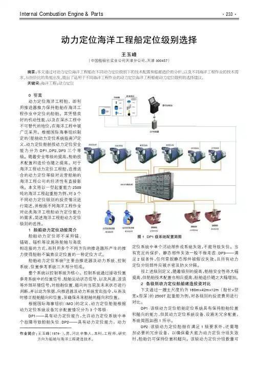
北京先略投资咨询有限公司船用动力定位DP系统概述(最新版报告请登陆我司官方网站联系) 公司网址: 目录船用动力定位DP系统概述 (3)第一节船用动力定位DP系统的定义和分类 (3)一、动力定位DP0系统 (3)二、动力定位DP1系统 (3)三、动力定位DP2系统 (3)四、动力定位DP3系统 (3)第二节船用动力定位DP系统的市场情况 (4)一、动力定位DP1系统的市场情况 (4)1、全球 (4)2、中国 (5)二、动力定位DP2系统的市场情况 (8)1、全球 (8)2、中国 (8)三、动力定位DP3系统的市场情况 (10)1、全球 (10)2、中国 (11)船用动力定位DP系统概述第一节船用动力定位DP系统的定义和分类国际海事组织和国际海洋工程承包商协会将DP定义为动力定位船舶需要装备的全部设备,包括动力系统、推进器系统和动力定位控制系统。
由于海上作业船舶对动力定位系统的可靠性要求越来越高,IMO和各国船级社都对DP提出了严格要求,制定了三个等级标准。
设备等级一(DP1):在单故障的情况下可能发生定位失常。
设备等级二(DP2):有源组件或发电机、推进器、配电盘遥控阀门等系统单故障时不会发生定位失常,但当电缆、管道、手控阀等静态元件发生故障时可能会发生定位失常。
设备等级三(DP3):任何但故障都不会导致定位失常。
DP的分级主要考虑设备的可靠性和冗余度,目的是对动力定位系统的设计标准、必须安装的设备、操作要求和试验程序等作出规定,保证DP安全可靠运行,并避免在DP作业时对人员、船舶、其他设备造成损害。
一、动力定位DP0系统DP0船舶装备一套集控手动操作系统和航向自动保持的动力定位系统(DPS),能在最大环境条件下,使船舶的位置和航向保持在限定范围内。
二、动力定位DP1系统DP1船舶装备具有自动定位和航向自动保持的动力定位系统(DPS),另外,还有一套独立的集控手动操作系统和航向自动保持的动力定位系统,能在最大环境条件下,使船舶的位置和航向保持在限定范围内。
第21卷第4期 中国惯性技术学报 V ol.21 No.4 2013年8月 Journal of Chinese Inertial Technology Aug. 2013 收稿日期:2013-01-24;修回日期:2013-06-21 基金项目:国家863计划重点项目(2011AA110201)作者简介:郑荣才(1973—),男,工学博士,高级工程师,研究方向为综合导航和多传感器数据融合技术。
E-mail :zrc618@文章编号:1005-6734(2013)04-0495-05船舶动力定位系统郑荣才,宋健力,黎 琼,吴园园,窦玉宝(天津航海仪器研究所,天津 300131)摘要:随着深海技术的不断发展,动力定位系统的在海洋工程上得到广泛应用。
动力定位系统通过其控制系统驱动船舶推进器来抵消风、浪、流等作用于船上的环境外力, 从而使船舶保持在确定的位置上或沿预期的航迹航行。
本文在分析了国际海事组织和国际海洋工程承包商协会对动力定位系统定义及分级要求的基础上,阐述了国外船舶动力定位系统的发展及其应用状况,分析了动力定位系统的组成和工作原理,研究了动力定位系统的各种约束、控制策略、控制技术、推力分配等关键技术,指出动力定位系统精度取决于控制系统和测量系统性能,并提出了发展国产动力定位系统应采用的途径。
关 键 词:动力定位系统;推力分配;测量系统;控制系统 中图分类号:U666.1文献标志码:ADynamic positioning system of shipZHENG Rong-cai, SONG Jian-li, LI Qiong, WU Yuan-yuan, DOU Yu-bao (Tianjin Navigation Instrument Research Institute, Tianjin 300131, China)Abstract: With the developments of deep-sea technologies, the dynamic positioning system(DPS) has been widely applied in offshore project. The dynamically positioned system of a vessel is designed to accurately maintain the vessel’s position and heading at a fixed location or a predetermined track for marine operation purposes by exclusively using active thrusters. In this paper, the development and application of the dynamic positioning(DP) system were investigated. The principle how the DP works was analyzed. The typical configurations of the foreign famous DPS were studied. The system restrictions, control strategy, control technology ,and thrust allocation of DP were analyzed. It was pointed that the accuracy of dynamic positioning system depends on dynamic positioning control and measurement equipment. Based on the researches above, an approach to develop our own dynamic positioning system was presented. Key words: dynamic positioning system; thrust allocation; measurement systems; control systems船舶动力定位(dynamic positioning ,DP) 系统是一种闭环控制系统,它通过控制系统驱动船舶推进器来抵消风、浪、流等作用于船上的环境外力, 从而使船舶保持在海平面某要求的位置上。
MSC/Circ.6456June1994IMOGUIDELINES FOR VESSELS WITH DYNAMIC POSITIONING SYSTEMS1The Maritime Safety Committee at its sixty-third session(16to25May1994), approved the Guidelines for Vessels with Dynamic Positioning Systems,set out atannex to the present circular,as prepared by the Sub-Committee on Ship Design and Equipment at its thirty-seventh session.2Member Governments are invited to bring the Guidelines to the attention of all bodies concerned,and apply the Guidelines to new vessels with dynamic positioning systems constructed on or after1July1994,in conjunction with implementation of the provisions of paragraph 4.12of the1989MODU Code as amended by resolution MSC.38(63).3Member Governments are also invited to use the proposed model form of flag State verification and acceptance document set out in the appendix to the Guidelines.ANNEXGUIDELINES FOR VESSELS WITH DYNAMIC POSITIONING SYSTEMSContentspage Preamble3 1General1.1Purpose and responsibility41.2Application41.3Definitions41.4Exemptions51.5Equivalents5 2Equipment classes6 3Functional requirements3.1General73.2Power system73.3Thruster system83.4DP-control system83.4.1General83.4.2Computers93.4.3Position reference systems103.4.4Vessel sensors103.5Cable and piping systems113.6Requirements for essential non-DP-systems11 4Operational requirements11 5Surveys,testing and the Flag State Verification12 and Acceptance Document(FSVAD)5.1Surveys and testing125.2Flag State Verification and Acceptance Document(FSVAD)13 Appendix:Model form of FSVAD14 PREAMBLE1These Guidelines for vessels with dynamic positioning systems have been developed to provide an international standard for dynamic positioning systems on all types of new vessel.2Taking into account that dynamically positioned vessels are moved and operated internationally and recognizing that the design and operating criteria require special consideration,the Guidelines have been developed to facilitate international operation without having to document the dynamic positioning system in detail for every new area of operation.3The Guidelines are not intended to prohibit the use of any existing vessel because its dynamic positioning system does not comply with these Guidelines.Many existing units have operated successfully and safely for extended periods of time and their operating history should be considered in evaluating their suitability to conduct dynamically positioned operations.4Compliance with the Guidelines will be documented by a Flag State Verification and Acceptance Document(FSVAD)for the dynamic positioning system.The purpose of a FSVAD is to ensure that the vessel is operated,surveyed and tested according to vessel specific procedures and that the results are properly recorded.5A coastal State may permit any vessel whose dynamic positioning system is designed to a different standard than that of these Guidelines to engage in operations.1GENERAL1.1Purpose and responsibility1.1.1The purpose of these Guidelines is to recommend design criteria,necessary equipment,operating requirements,and a test and documentation system for dynamic positioning systems to reduce the risk to personnel,the vessel,other vessels or structures, sub-sea installations and the environment while performing operations under dynamic positioning control.1.1.2The responsibility for ensuring that the provisions of the Guidelines are complied with rests with the owner of the DP-vessel.1.2ApplicationThe Guidelines apply to dynamically positioned units or vessels,the keel of which is laid or which is at a similar stage of construction on or after1July1994.1.3DefinitionsIn addition to the definitions in the MODU Code1989the following definitions are necessary for the guidelines:1.3.1"Dynamically positioned vessel(DP-vessel)"means a unit or a vessel which automatically maintains its position(fixed location or predetermined track)exclusively by means of thruster force.1.3.2"Dynamic positioning system(DP-system)"means the complete installation necessary for dynamically positioning a vessel comprising the following sub-systems:.1power system,.2thruster system,and.3DP-control system.1.3.3"Position keeping"means maintaining a desired position within the normal excursions of the control system and the environmental conditions.1.3.4"Power system"means all components and systems necessary to supply the DP-system with power.The power system includes:.1prime movers with necessary auxiliary systems including piping,.2generators,.3switchboards,and.4distributing system(cabling and cable routeing).1.3.5"Thruster system"means all components and systems necessary to supply the DP-system with thrust force and direction.The thruster system includes:.1thrusters with drive units and necessary auxiliary systems including piping,.2main propellers and rudders if these are under the control of the DP-system,.3thruster control electronics,.4manual thruster controls,and.5associated cabling and cable routeing.1.3.6"DP-control system"means all control components and systems,hardware andsoftware necessary to dynamically position the vessel.The DP-control system consists of the following:.1computer system/joystick system,.2sensor system,.3display system(operator panels),.4position reference system,and.5associated cabling and cable routeing.1.3.7"Computer system"means a system consisting of one or several computers including software and their interfaces.1.3.8"Redundancy"means ability of a component or system to maintain or restore its function,when a single failure has occurred.Redundancy can be achieved for instance by installation of multiple components,systems or alternative means of performing a function.1.3.9"Flag State Verification and Acceptance Document(FSVAD)"means the document issued by the Administration to a DP-vessel complying with these Guidelines.(See Appendix for model form.)1.4ExemptionsAn Administration may exempt any vessel which embodies features of a novel kind from any provisions of the guidelines the application of which might impede research into the development of such features.Any such vessels should,however,comply with safety requirements which,in the opinion of the Administration,are adequate for the service intended and are such as to ensure the overall safety of the vessel.The Administration which allows any such exemptions should list the exemptions on the Flag State Verification and Acceptance Document(FSVAD)and communicate to the Organization the particulars,together with the reason therefor,so that the Organization may circulate the same to other Governments for the information of their officers.1.5Equivalents1.5.1Where the Guidelines require that a particular fitting,material,appliance,apparatus, item of equipment or type thereof should be fitted or carried out in a vessel,or that any particular provision should be made,or any procedure or arrangement should be complied with,the Administration may allow other fitting,material,appliance,apparatus,item of equipment or type thereof to be fitted or carried,or any other provision,procedure or arrangement to be made in that vessel,if it is satisfied by trial thereof or otherwise that such fitting,material,appliance,apparatus,item of equipment or type thereof or that any particular provision,procedure or arrangement is at least as effective as that required by the Guidelines.1.5.2When an Administration so allows any fitting,material,appliance,apparatus,item of equipment or type thereof,or provision,procedure,arrangement,novel design or application to be substituted,it should communicate to the Organization the particulars thereof,together with a report on the evidence submitted,so that the Organization may circulate the same to other Governments for information of their officers.2EQUIPMENT CLASSES2.1A DP-system consists of components and systems acting together to achieve sufficiently reliable position keeping capability.The necessary reliability is determined by the consequence of a loss of position keeping capability.The larger the consequence,the more reliable the DP-system should be.To achieve this philosophy the requirements have been grouped into three equipment classes.For each equipment class the associated worst case failure should be defined as in2.2below.The equipment class of the vessel required for a particular operation should be agreed between the owner of the vessel and the customer based on a risk analysis of the consequence of a loss of position.Else,the Administration or coastal State may decide the equipment class for the particular operation.2.2The equipment classes are defined by their worst case failure modes as follows:.1For equipment class1,loss of position may occur in the event of a single fault..2For equipment class2,a loss of position is not to occur in the event of a single fault in any active component or system.Normally static components will not be considered to fail where adequate protection from damage is demonstrated,and reliability is to the satisfaction of the Administration.Single failure criteria include:.1Any active component or system(generators,thrusters,switchboards,remote controlled valves,etc.)..2Any normally static component(cables,pipes,manual valves,etc.)which is not properly documented with respect to protection and reliability..For equipment class3,a single failure includes:.1Items listed above for class2,and any normally static component is assumed to fail..2All components in any one watertight compartment,from fire or flooding..3All components in any one fire sub-division,from fire or flooding(for cables, see also3.5.1).2.3For equipment classes2and3,a single inadvertent act should be considered as a single fault if such an act is reasonably probable.2.4Based on the single failure definitions in 2.2the worst case failure should be determined and used as the criterion for the consequence analysis(see3.4.2.4).2.5The Administration should assign the relevant equipment class to a DP-vessel based on the criteria in 2.2and state it in the Flag State Verification and Acceptance Document (FSVAD)(see5.2).2.6When a DP-vessel is assigned an equipment class this means that the DP-vessel is suitable for all types of DP-operations within the assigned and lower equipment classes.2.7It is a provision of the guidelines that the DP-vessel is operated in such a way that the worst case failure,as determined in 2.2,can occur at any time without causing a significant loss of position.3FUNCTIONAL REQUIREMENTS3.1General3.1.1In so far as is practicable all components in a DP-system should be designed, constructed and tested in accordance with international standards recognized by the Administration.3.1.2In order to meet the single failure criteria given in 2.2,redundancy of components will normally be necessary as follows:.1for equipment class2,redundancy of all active components;.2for equipment class3,redundancy of all components and physical separation of the components.3.1.3For equipment class3,full redundancy may not always be possible(e.g.,there may be a need for a single change-over system from the main computer system to the back-up computer system).Non-redundant connections between otherwise redundant and separated systems may be accepted provided that it is documented to give clear safety advantages, and that their reliability can be demonstrated and documented to the satisfaction of the Administration.Such connections should be kept to the absolute minimum and made to fail to the safest condition.Failure in one system should in no case be transferred to the other redundant system.3.1.4Redundant components and systems should be immediately available and with such capacity that the DP-operation can be continued for such a period that the work in progress can be terminated safely.The transfer to redundant component or system should be automatic as far as possible,and operator intervention should be kept to a minimum. The transfer should be smooth and within acceptable limitations of the operation.3.2Power system3.2.1The power system should have an adequate response time to power demand changes.3.2.2For equipment class1the power system need not be redundant.3.2.3For equipment class2,the power system should be divisible into two or more systems such that in the event of failure of one system at least one other system will remain in operation.The power system may be run as one system during operation,but should be arranged by bus-tie breakers to separate automatically upon failures which could be transferred from one system to another,including overloading and short-circuits.3.2.4For equipment class3,the power system should be divisible into two or more systems such that in the event of failure of one system,at least one other system will remain in operation.The divided power system should be located in different spaces separated by A.60class division.Where the power systems are located below the operational waterline,the separation should also be watertight.Bus-tie breakers should be open during equipment class3operations unless equivalent integrity of power operation can be accepted according to3.1.3.3.2.5For equipment classes2and3,the power available for position keeping should be sufficient to maintain the vessel in position after worst case failure according to2.2.3.2.6If a power management system is installed,adequate redundancy or reliability to thesatisfaction of the Administration should be demonstrated.3.3Thruster system3.3.1The thruster system should provide adequate thrust in longitudinal and lateral directions,and provide yawing moment for heading control.3.3.2For equipment classes2and3,the thruster system should be connected to the power system in such a way that 3.3.1can be complied with even after failure of one of the constituent power systems and the thrusters connected to that system.3.3.3The values of thruster force used in the consequence analysis(see3.4.2.4)should be corrected for interference between thrusters and other effects which would reduce the effective force.3.3.4Failure of thruster system including pitch,azimuth or speed control,should not make the thruster rotate or go to uncontrolled full pitch and speed.3.4DP-control system3.4.1General.1In general the DP-control system should be arranged in a DP-control station where the operator has a good view of the vessel's exterior limits and the surrounding area..2The DP-control station should display information from the power system,thruster system,and DP-control system to ensure that these systems are functioning rmation necessary to operate the DP-system safely should be visible at all times.Other information should be available upon operator request..3Display systems and the DP-control station in particular,should be based on sound ergonometric principles.The DP-control system should provide for easy selection of control mode,i.e.manual,joystick,or computer control of thrusters, and the active mode should be clearly displayed..4For equipment classes2and3,operator controls should be designed so that no single inadvertent act on the operators'panel can lead to a critical condition..5Alarms and warnings for failures in systems interfaced to and/or controlled by the DP-control system are to be audible and visual.A permanent record of their occurrence and of status changes should be provided together with any necessary explanations..6The DP-control system should prevent failures being transferred from one system to another.The redundant components should be so arranged that a failure of one component should be isolated,and the other component activated..7It should be possible to control the thrusters manually,by individual joysticks and by a common joystick,in the event of failure of the DP-control system..8The software should be produced in accordance with an appropriate international quality standard recognized by the Administration.3.4.2Computers.1For equipment class1,the DP-control system need not be redundant..2For equipment class2,the DP-control system should consist of at least two independent computer mon facilities such as self-checking routines, data transfer arrangements,and plant interfaces should not be capable of causingthe failure of both/all systems..3For equipment class3,the DP-control system should consist of at least two independent computer systems with self-checking and alignment facilities.Common facilities such as self-checking routines,data transfer arrangements and plant interfaces should not be capable of causing failure at both/all systems.In addition,one back-up DP-control system should be arranged,see 3.4.2.6.An alarm should be initiated if any computer fails or is not ready to take control..4For equipment classes2and3,the DP-control system should include a software function,normally known as'consequence analysis',which continuously verifies that the vessel will remain in position even if the worst case failure occurs.This analysis should verify that the thrusters remaining in operation after the worst case failure can generate the same resultant thruster force and moment as required before the failure.The consequence analysis should provide an alarm if the occurrence of a worst case failure would lead to a loss of position due to insufficient thrust for the prevailing environmental conditions.For operations which will take a long time to safely terminate,the consequence analysis should include a function which simulates the thrust and power remaining after the worse case failure,based on manual input of weather trend..5Redundant computer systems should be arranged with automatic transfer of control after a detected failure in one of the computer systems.The automatic transfer of control from one computer system to another should be smooth,and within the acceptable limitations of the operation..6For equipment class3,the back-up DP-control system should be in a room separated by A.60class division from the main DP-control station.During DP-operation this back-up control system should be continuously updated by input from the sensors,position reference system,thruster feedback,etc.,and be ready to take over control.The switch-over of control to the back-up system should be manual,situated on the back-up computer and should not be affected by failure of the main DP-control system..7An uninterruptible power supply(UPS)should be provided for each DP-computer system to ensure that any power failure will not affect more than one computer.UPS battery capacity should provide a minimum of30minutes operation following a mains supply failure.3.4.3Position reference systems.1Position reference systems should be selected with due consideration to operational requirements,both with regard to restrictions caused by the manner of deployment and expected performance in working situation..2For equipment classes2and3,at least three position reference systems should be installed and simultaneously available to the DP-control system during operation..3When two or more position reference systems are required,they should not all be of the same type,but based on different principles and suitable for the operating conditions..4The position reference systems should produce data with adequate accuracy for the intended DP-operation..5The performance of position reference systems should be monitored and warnings provided when the signals from the position reference systems are either incorrect or substantially degraded..6For equipment class3,at least one of the position reference systems should be connected directly to the back-up control system and separated by A.60class division from the other position reference systems.3.4.4Vessel sensors.1Vessel sensors should at least measure vessel leading,vessel motions,and wind speed and direction..2When an equipment class2or3DP-control system is fully dependent on correct signals from vessel sensors,then these signals should be based on three systems serving the same purpose(i.e.this will result in at least three gyro compasses being installed)..3Sensors for the same purpose,connected to redundant systems should be arranged independently so that failure of one will not affect the others..4For equipment class3,one of each type of sensors should be connected directly to the back-up control system and separated by A.60class division from the other sensors.3.5Cables and piping systems3.5.1For equipment class3,cables for redundant equipment or systems should not be routed together through the same compartments.Where this is unavoidable such cables could run together in cable ducts of A-60class,the termination of the ducts included, which are effectively protected from all fire hazards,except that represented by the cables themselves.Cable connection boxes are not allowed in such ducts.3.5.2For equipment class2,piping systems for fuel,lubrication,hydraulic oil,cooling water and cables should be located with due regard to fire hazards and mechanical damage.3.5.3For equipment class3,redundant piping system(i.e.piping for fuel,cooling water, lubrication oil,hydraulic oil,etc.)should not be routed together through the same compartments.Where this in unavoidable,such pipes could run together in ducts of A-60 class,the termination of the ducts included,which are effectively protected from all fire hazards,except that represented by the pipes themselves.3.6Requirements for essential non-DP-systemsFor equipment classes2and3,systems not directly part of the DP-system but which in the event of failure could cause failure of the DP-system,(e.g.,common fire suppression systems,engine ventilation systems,shut-down systems,etc.),should also comply with relevant requirements of these Guidelines.4OPERATIONAL REQUIREMENTS4.1Before every DP-operation,the DP-system should be checked according to a vessel specific"location"check list to make sure that the DP-system is functioning correctly and that the system has been set up for the appropriate equipment class.4.2During DP-operations,the system should be checked at regular intervals according toa vessel specific watchkeeping checklist.4.3DP operations necessitating equipment class2or3should be terminated when the environmental conditions are such that the DP-vessel will no longer be able to keep position if the single failure criterion applicable to the equipment class should occur.In this context deterioration of environmental conditions and the necessary time to safely terminate the operation should also be taken into consideration.This should be checked by way of environmental envelopes if operating in equipment class1and by way of an automatic consequence analysis if operating in equipment class2or 3.The necessary operating instructions,etc.,should be on board.4.4The following checklists,test procedures and instructions should be incorporated into the DP operating manuals for the vessel:.1Location checklist(see4.1)..2Watchkeeping checklist(see4.2)..3DP-operation instructions(see4.3)..4Annual tests and procedures(see5.1.1.3)..5Initial and periodical(5-year)tests and procedures(see5.1.1.1and5.1.1.2)..6Example of tests and procedures after modifications and non-conformities(see5.1.1.4).5SURVEYS,TESTING AND THE FLAG STATE VERIFICATION AND ACCEPTANCE DOCUMENT(FSVAD)5.1Surveys and testing5.1.1Each DP-vessel which is required to comply with the Guidelines is subject to the surveys and testing specified below:.1Initial survey which should include a complete survey of the DP-system to ensure full compliance with the applicable parts of the guidelines.Further it includes a complete test of all systems and components and the ability to keep position after single failures associated with the assigned equipment class.The type of test carried out and results should be documented in the Flag State Verification and Acceptance Document(FSVAD),see5.2..2Periodical survey at intervals not exceeding five years to ensure full compliance with the applicable parts of the guidelines.A complete test should be carried out as required in 5.1.1.1.The type of test carried out and the results should be documented in the FSVAD,see5.2..3Annual survey should be carried out within three months before or after each anniversary date of the initial survey.The annual survey should ensure that the DP-system has been maintained in accordance with applicable parts of the guidelines and is in good working order.Further an annual test of all important systems and components should be carried out to document the ability of the DP-vessel to keep position after single failures associated with the assigned equipment class.The type of test carried out and results should be documented in the FSVAD,see5.2..4A survey either general or partial according to circumstances should be made every time a defect is discovered and corrected or an accident occurs which affects the safety of the DP-vessel,or whenever any significant repairs or alterations are made.After such a survey,necessary tests should be carried out to demonstrate full compliance with the applicable provisions of the Guidelines.The type of tests carried out and results should be recorded and kept on board.5.1.2These surveys and tests should be witnessed by officers of the Administration.The Administration may,however,entrust the surveys and testing either to surveyors nominated for the purpose or to organizations recognized by it.In every case the Administration concerned should fully guarantee the completeness and efficiency of the surveys and testing.The Administration may entrust the owner of the vessel to carry out annual and minor repair surveys according to a test programme accepted by the Administration.5.1.3After any survey and testing has been completed,no significant change should be made to the DP-system without the sanction of the Administration,except the direct replacement of equipment and fittings for the purpose of repair or maintenance.5.2Flag State Verification and Acceptance Document(FSVAD)5.2.1A Flag State Verification and Acceptance Document(FSVAD)should be issued,after survey and testing in accordance with these Guidelines,either by officers of the Administration or by an organization duly authorized by it.In every case the Administration assumes full responsibility for the FSVAD.5.2.2The FSVAD should be drawn up in the official language of the issuing country and be that of the model given in the appendix to the Guidelines.If the language used is neither English nor French,the text should include a translation into one of these languages.5.2.3The FSVAD is issued for an unlimited period,or for a period specified by the Administration.5.2.4An FSVAD should cease to be valid if significant alterations have been made in the DP-system equipment,fittings,arrangements,etc.,specified in the Guidelines without the sanction of the Administration,except the direct replacement of such equipment or fittings for the purpose of repair or maintenance.5.2.5An FSVAD issued to a DP-vessel should cease to be valid upon transfer of such a vessel to the flag of another country.5.2.6The privileges of the FSVAD may not be claimed in favour of any DP-vessel unless the FSVAD is valid.5.2.7Control of a DP-vessel holding a valid FSVAD should be carried out according to the principles of1.7in the MODU Code1989.5.2.8Results of the FSVAD tests should be readily available on board for reference.。
imo 目标型船舶建造标准
IMO(国际海事组织)是负责制定国际船舶建造标准的主要组织
之一。
IMO的目标型船舶建造标准涉及许多方面,包括船舶结构、
材料、设备、系统和操作规程等。
以下是 IMO 目标型船舶建造标准
的一些方面:
1. 结构标准,IMO制定了船舶结构的设计和建造标准,以确保
船舶在各种海况下具有足够的强度和稳定性。
这包括船体的设计、
各部件的材料和连接方式等。
2. 材料标准,IMO规定了船舶建造所使用的材料的标准和规范,以确保其符合船舶建造的要求,具有足够的强度和耐久性,同时也
要考虑材料的环保性能。
3. 设备标准,IMO对船舶上安装的设备,如引擎、舵机、通信
设备等,制定了相应的标准和要求,以确保其符合国际安全要求和
操作规程。
4. 系统标准,IMO要求船舶建造符合一系列系统标准,包括动
力系统、电气系统、排水系统、消防系统等,以确保船舶在各种情
况下都能正常运行和应对突发事件。
5. 操作规程,除了船舶的设计和建造标准外,IMO还规定了船舶的操作规程,包括船员的培训要求、航行规则、安全程序等,以确保船舶的安全运行。
总的来说,IMO目标型船舶建造标准涵盖了船舶建造的方方面面,旨在确保船舶的设计、建造和操作都符合国际标准,以保障航行安全和环境保护。
这些标准对于船舶制造商、船东、船员和相关监管部门都具有重要意义。
![[冗余,动力,系统]DP―3动力定位冗余系统设计与分析](https://uimg.taocdn.com/e039b9d9ba1aa8114531d9c7.webp)
DP―3动力定位冗余系统设计与分析摘要:介绍国际海事组织对DP-3动力定位冗余系统的基本要求,分析目前主流的设计与系统布置上的要求。
通过实际的工程实例,对比分析两种不同的设计思路以及两种冗余系统FMEA的接受标准,可作为工程设计的参考。
关键词:动力定位;冗余;DP-3随着海洋钻探从浅海向深水及超深水区域发展,传统的锚泊定位系统锚链长度和强度都要增加,进而船舶重量增加,钻井甲板上的可变载荷减小,设备布置困难等缺点随之出现。
同时,锚泊定位系统也有自身的缺点,其较低的弹性和流体动力阻尼等使船舶一直暴露在风浪流的影响下,操作性和安全性都受到影响。
因此,发展高性能的动力定位系统(Dynamic Positioning System)成为深水海洋钻探的趋势。
自上个世纪60年代起,伴随着北海区域以及墨西哥湾海上油气田的开发,几大船级社、当地行业组织以及国际行业协会等对动力定位系统规范进行了大量的研究,并出台了众多的规范。
1994年国际海事组织出台了MSC Circ.645《GUIDELINES FOR VESSELS WITH DYNAMIC POSITIONING SYSTEMS》作为目前对动力定位系统的一个统一的法定要求。
随后,以DNV、ABS、LR、CCS等船级社为代表,以MSC Circ.645为基本准则,相继发展了自己的最新规范。
1.DP-3动力定位系统冗余理念的发展虽然从20世纪早期已经有很多国外公司研究生产船舶、海洋平台的动力定位系统,但是从真正意义上的自动动力定位系统起源于1961年,当时采用了四点系泊加四台手动可调螺旋桨,另外艏艉各配备一台360度全回转推进器,1971年自动动力定位系统第一次应用于航海钻井。
随着技术的发展,1980年,全球卫星定位系统(GPS)被引入,大大提升了系统的定位精度。
直到现在,DP-3动力定位系统的设计与物理双冗余的高冗余度概念以及闭环电网技术的采用,大大提升了系统的可靠性,并且降低了系统能耗。
动力定位船舶的FMEA介绍
沈锦康
【期刊名称】《江苏船舶》
【年(卷),期】2010(027)003
【摘要】围绕DP2和DP3动力定位船舶的设计、建造、检验及运营管理, 介绍了FMEA在整个周期中所起的重要作用,结合各船级社和 IMO规范要求,详述了FMEA 的概念,分析和试验的方法、步骤和流程,并对单点故障、冗余等相关概念作了具体描述;最后简述了船舶DP操作手册的基本概念.
【总页数】5页(P26-29,32)
【作者】沈锦康
【作者单位】中国石化集团上海海洋石油局,上海,201206
【正文语种】中文
【中图分类】U674.38
【相关文献】
1.FMEA 在动力定位钻井平台中的广泛应用 [J], 孙玮
2.基于模糊评价和灰色关联度的动力定位系统FMEA方法 [J], 何祖军;戴三淞;杨奕飞
3.FMEA和FCE方法在动力定位控制系统中的应用 [J], 付明玉;宁继鹏;魏玉石;刘杨
4.某船动力定位系统配置及FMEA试验研究 [J], 陈明
5.船舶动力定位系统与锚泊辅助动力定位系统的时域模拟比较 [J], 周利; 王磊
因版权原因,仅展示原文概要,查看原文内容请购买。
IMO动力定位系统规范介绍IMO动力定位系统规范(动力位置标准)是由国际海事组织(IMO)制定的一套关于船舶动力定位系统的国际标准。
该规范旨在确保船舶动力定位系统在执行定位任务时的安全性、可靠性和效率。
下面将介绍IMO动力定位系统规范的主要内容和意义。
IMO动力定位系统规范针对的是可用于航海和海洋工程等领域的动力定位系统(DPS),该系统通过控制船舶的动力系统来保持船舶在指定位置或轨迹上的运动。
在许多应用中,船舶需要固定在一个特定的位置上进行工作,如海洋钻探、海底管线安装等。
动力定位系统可以提供准确的位置和运动控制,使船舶能够在恶劣的环境条件下保持稳定运动,并帮助船舶进行需要高度精确度的操作。
1.动力定位系统的分类:根据不同的应用和特点,动力定位系统可以分为不同的等级。
规范对各个等级的动力定位系统的要求进行了详细说明,包括系统的设备、控制和操作要求等。
2.设备要求:规范详细描述了动力定位系统的各个关键设备的规格和要求,包括定位传感器、船舶动力装置、控制系统等。
这些设备需要符合一定的标准,以确保系统的可靠性和安全性。
3.系统架构:规范规定了动力定位系统的整体架构,包括系统的组成部分和各个部件之间的连接关系。
系统的可靠性和完整性取决于合理的架构设计和可靠的通信和控制连接。
4.操作要求:规范对动力定位系统的操作人员提出了一系列要求。
操作人员需要经过专门的培训和资质认证,熟悉系统的操作流程和操作要点,能够及时有效地响应各种工作条件和应急情况。
5.安全要求:规范关注船舶动力定位系统在遭遇各种异常情况时的安全性问题。
例如,如果发生系统故障、定位传感器失效或动力装置故障等情况,系统应该能够自动切换到备用方案或发出警报来保证船舶的安全。
IMO动力定位系统规范对船舶动力定位系统的设计、制造、安装和操作均提出了严格要求,以确保系统在实际应用中的可靠性和安全性。
这些规范为动力定位系统的生产商、供应商和用户提供了参考标准,为航海和海洋工程提供了有力的技术支持。
给定的最严峻环境条件给定的最严峻环境条件系指船舶作业区域内的最大风速﹑流速与浪高。
根据不同工况要求和操作要求,调整DP等级,以降低能耗和对周边环境的影响。
主要DP控制系统供应商“绿色DP” 控制系统控制器全回转推进器硬线或网络侧推推进用推进器一般的位置测量设备•扇形波束测位仪(激光技术)Fan Beam (Laser Technique)•张紧索(测垂向倾角);Taut Wire (Vertical Angle)•差分式全球卫星定位系统DGPS (借助卫星)•水下声学定位系统HPR (有长﹑短基线等方法,需水下声学应答器,水下声学技术);HPR(Long &Short Base, Hydro‐acoustic, Transponders)•Atriums (无线电波,需要岸上参考目标,适用于特定位置)Atriums (Radio Wave, Landmark, SpecificSite)•其他设备Others联合操纵杆零级定位DPS‐0适用于安装有动力定位系统的船舶,它具有集中手动位置控制和自动艏向控制,在给定的最严峻环境条件下,能保持船舶的位置和艏向。
For vessels which are fitted with a dynamicpositioning system with centralized manual positioncontrol and automatic heading control to maintain the position and heading under the specifiedmaximum environmental conditions.一个典型的DPS‐2系统内部构成A Typical DPS‐2 Configuration双操作站双控制器三级定位DPS‐3适用于安装有动力定位系统的船舶,在给定的最严峻环境条件下,包括发生任何单一故障(包括由于火灾或水灾而失去整个舱室),能自动保持船舶的位置和艏向在给定的运行范围内。
动力定位操作规程动力定位操作规程是指在船舶进行动力定位作业时,根据相关规定和操作要求,制定的具体操作指导规范。
下面将从前期准备、操作流程、应急措施等方面介绍动力定位操作规程。
一、前期准备1. 确保船舶设备完好:检查动力定位系统、舵系统、主机系统等设备的工作状态和运行情况,确保设备正常工作。
2. 制定动力定位作业计划:根据实际情况制定动力定位作业计划,包括作业区域的选择、动力定位系统参数的设置、作业时间安排等。
3. 确定作业区域:根据实际情况确定作业区域,并在地图上标注出重要的地标点和障碍物。
4. 完善作业记录和报告:明确通讯和记录作业进程的方式,确保作业记录准确完整。
二、操作流程1. 启动船舶设备:按照设备启动顺序,启动动力定位系统、舵系统及主机系统等设备。
2. 系泊固定船舶:利用锚或系泊装置,将船舶固定在作业区域内。
3. 设置动力定位系统参数:根据作业实际需要,设置动力定位系统的参数,包括定位方式、定位精度等。
4. 启动动力定位系统:根据设备使用说明书操作,启动动力定位系统。
5. 控制船舶位置:通过舵机和主机控制系统,控制船舶的位置和移动方向,确保船舶在指定区域内保持合适的位置。
6. 监测和调整:通过监测设备数据和船舶位置,根据实际情况进行调整,确保船舶位置控制在合适范围内。
7. 完成作业并停止设备:完成作业任务后,按照设备停止顺序,依次停止动力定位系统、舵系统及主机系统等设备。
三、应急措施1. 突发情况处理:在遇到突发情况时,操作人员应立即采取措施,如停止设备、调整船舶位置等,确保船舶安全。
2. 紧急停止设备:在遇到突发情况或出现设备故障时,应立即停止设备,同时及时向相关人员报告情况并寻求支持和协助。
3. 报警和通讯:在遇到危险情况时,应及时通过设备报警系统向岸上报警,并与相关人员保持通讯,确保及时应对突发情况。
4. 疏散和求救:在危险情况无法控制时,按照应急预案和安全操作规程,组织船员疏散和求救。
“大洋一号”船的动力定位系统随着人类越来越多地涉足于海上,对船舶与海洋平台系泊方式的研究也变得日益重视。
由于通常的锚泊方式在深海的应用受到很大限制,因此,不借助于锚泊系统的动力定位系统便应运而生。
船舶动力定位系统在20世纪60年代开始初现雏形,在20世纪70年代后期随着计算机技术的发展以及西欧北海油田的需求而获得了长足进步与飞跃发展,至20世纪末期已进入成熟阶段。
船舶动力定位系统近年在国外发展十分迅猛,在军民用特种船舶上获得了广泛应用。
据不完全统计,在20世纪70年代末期,全世界装备动力定位系统的船舶与海上平台不超过30艘;到2000年底突破了1000艘;到2002年底超过了1200艘。
自1977年挪威船级社首先发布了船舶动力定位规范后,在20世纪90年代中后期,国外各大船级社均先后规定了相应规范。
动力定位就是船舶或海上平台不借助于锚泊系统的作用,而是利用自身装备的各类传感器测出船舶的运动状态与位置变化,以及外界风力、波浪、海流等扰动力的大小与方向,利用计算机进行复杂的实时计算,控制船舶主副推力装置产生适当的推力与力矩,以抵消扰动力,使船舶尽可能保持目标船位与艏向。
随着动力定位技术的发展,动力定位的概念也在扩大。
采用动力定位技术,还可以使船舶与其他船只保持相对位置不变、使船舶按预定轨迹移位、按预定计划航线以预定航速航行、实现船舶自动驾驶、对水下目标进行自动跟踪等功能。
动力定位系统首先应用于海上石油钻探船、有缆遥控水下潜器(ROV)母船、消防船等需要深海定点作业的特种船舶。
从20世纪80年代开始,动力定位系统已广泛应用于海洋考察船、钻探船、打捞船、采矿船、布缆船、敷管船、挖泥船、消防船、起重船、潜水支持船、浮式采储油系统(FPSO)、海上供应船、特种工作船、高级游船、穿梭油轮等特种船舶,在军事方面也应用于布雷舰、扫雷舰、侦察船、航海保障调查船、潜艇母船、救助船、海上补给船等舰船。
◎ 何崇德(中船重工集团公司第七○一研究所 “大洋一号”船副总设计师兼主任设计师)动力定位系统原理船舶在海上除了受到本身推进器的推力以外,还受到风力、波浪与海流的外界作用力,从而产生6个自由度的运动,即纵荡、横荡、升沉、纵摇、横摇与艏摇。