虚拟路由冗余协议(vrrp)简介
- 格式:doc
- 大小:36.50 KB
- 文档页数:4
HSRP和VRRP的区别- -1.在功能上,VRRP和HSRP非常相似,但是就安全而言,VRRP对HSRP的一个主要优势:它允许参与VR RP组的设备间建立认证机制.并且,不像HSRP那样要求虚拟路由器不能是其中一个路由器的ip地址,但是V RRP允许这种情况发生(如果”拥有”虚拟路由器地址的路由器被建立并且正在运行,那么应该总是由这个虚拟路由器管理—等价于HSRP中的活动路由器),但是为了确保万一失效发生的时候终端主机不必重新学习MAC地址,它指定使用的MAC地址00-00-5e-00-01-VRID,这里的VRID是虚拟路由器的ID(等价于一个HS RP的组标识符).2.另外一个不同是VRRP不使用HSRP中的政变或者一个等价消息,VRRP的状态机比HSRP的要简单, HSRP有6个状态(初始(Initial)状态,学习(Learn)状态,监听(Listen)状态,对话(Speak)状态,备份(Stand by)状态,活动(Active)状态)和8个事件, VRRP只有3个状态(初始状态(Initialize)、主状态(Master)、备份状态(Backup))和5个事件.3. HSRP有三种报文,而且有三种状态可以发送报文呼叫(Hello)报文,告辞(Resign)报文,突变(Coup)报文VRRP有一种报文VRRP广播报文:由主路由器定时发出来通告它的存在,使用这些报文可以检测虚拟路由器各种参数,还可以用于主路由器的选举。
4. HSRP将报文承载在UDP报文上,而VRRP承载在TCP报文上(HSRP 使用UDP 1985端口,向组播地址224.0.0.2 发送hello消息。
)5.VRRP的安全:VRRP协议包括三种主要的认证方式:无认证,简单的明文密码和使用MD5 HMAC ip 认证的强认证.强认证方法使用IP认证头(AH)协议.AH是与用在IPSEC中相同的协议,AH为认证VRRP分组中的内容和分组头提供了一个方法. MD5 HMAC 的使用表明使用一个共享的密钥用于产生hash值.路由器发送一个VRRP分组产生MD5 hash值,并将它置于要发送的通告中,在接收时,接受方使用相同的密钥和MD5值,重新计算分组内容和分组头的hash值,如果结果相同,这个消息就是真正来自于一个可信赖的主机,如果不相同,它必须丢弃,这可以防止攻击者通过访问LAN而发出能影响选择过程的通告消息或者其他一些方法中断网络.另外,VRRP包括一个保护VRRP分组不会被另外一个远程网络添加内容的机制(设置TTL值=255,并在接受时检查),这限制了可以进行本地攻击的大部分缺陷.而另一方面,HSRP在它的消息中使用的TTL值是1.6.VRRP的崩溃间隔时间:3*通告间隔+时滞时间(skew-time)虚拟路由器冗余协议虚拟路由器冗余协议(VRRP:Virtual Router Redundancy Protocol)虚拟路由器冗余协议(VRRP)是一种选择协议,它可以把一个虚拟路由器的责任动态分配到局域网上的VRRP 路由器中的一台。
VRRP配置及多备份VRRP配置实例中兴通讯数据用服部钱月玫1 VRRP概念介绍VRRP全称是虚拟路由器冗余协议(Virtual Router Redundancy Protocol)。
为了理解VRRP,首先需要确定下列术语:●VRRP路由器:运行VRRP协议的路由器。
该路由器可以是一个或多个虚拟路由器。
●虚拟路由器:一个由VRRP协议管理的抽象对象,作为一个共享LAN内主机的缺省路由器。
它由一个虚拟路由器标识符(VRID)和同一LAN中一组关联IP地址组成。
一个VRRP路由器可以备份一个或多个虚拟路由器。
●IP地址所有者:将局域网的接口地址作为虚拟路由器的IP地址的路由器。
当运行时,该路由器将响应寻址到该IP地址的数据包。
●主虚拟路由器:该VRRP路由器将承担下列任务:转发那些寻址到与虚拟路由器关联的IP地址的数据包,应答对该IP地址的ARP请求。
注意,如果存在IP地址所有者,那么该所有者总是主虚拟路由器。
●备份虚拟路由器:一组可用的VRRP路由器,当主虚拟路由器失效后将承担主虚拟路由器的转发功能。
2 VRRP的工作机制VRRP把在同一个广播域中的多个路由器接口编为一组,形成一个虚拟路由器,并为其分配一个IP地址,作为虚拟路由器的接口地址。
虚拟路由器的接口地址既可以是其中一个路由器接口的地址,也可以是第三方地址。
如果使用路由器的接口地址作为VRRP虚拟地址,则拥有这个IP地址的路由器作为主用路由器,其他路由器作为备份。
如果采用第三方地址,则优先级高的路由器成为主用路由器;如果两路由器优先级相同,则谁先发VRRP 报文,谁就成为主用。
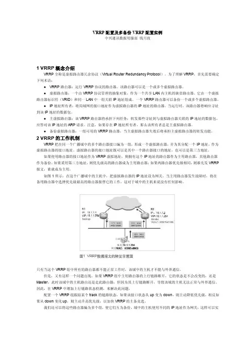
如图1所示,在这个广播域中的主机中,把虚拟路由器的IP地址设为网关。
当主用路由器发生故障时,将在备用路由器中选择优先级最高的路由器接替它的工作,这对于域中的主机来说没有任何影响。
只有当这个VRRP组中所有的路由器都不能正常工作时,该域中的主机才不能与外界通信。
但是,又有这样一个问题出现,如果VRRP组中主用路由器的上行链路断开,它的状态是不会改变的,还是Master,此时该域中的主机路由还是走此路由器,但因为其上行链路断开,导致该域的主机无法正常与外界通信。
VRRP的原理和运用虚拟路由器冗余协议(VRRP)是一种用于提高网络中设备冗余性和可靠性的协议。
本文将介绍VRRP的原理和运用。
VRRP的原理VRRP将多个路由器组成一个虚拟路由器组(VRG),VRG中有一个设备被指定为虚拟路由器(Virtual Router,VR),其余设备为备份路由器(Backup Router,BR)。
VR和BR均被赋予一个虚拟IP地址,VR会监视虚拟IP地址状态,当其无法提供服务时,备份路由器将自动接管虚拟IP地址提供服务,从而保证网络的连通性。
VRRP运行流程1.一个Virtual Router ID(VRID)被定义并分配给VRG,其值为0~255,同一VRG内的VR和BR共享同一个VRID。
2.VR和BR通过互相发送VRRP报文,确定VR和BR所在的VRG,并协商谁扮演VR的角色。
3.当VR和BR成功协商后,VR将发送一个VRRP组播报文,其中包含VR的MAC地址和虚拟IP地址。
4.路由表中指向VR的所有路由器都将被通知使用VR的MAC地址。
5.备份路由器会定期发送VRRP报文,以检查VR的状态,当VR无法回应时,备份路由器会接管虚拟IP地址,成为新的主机。
VRRP的优点使用VRRP的好处包括:1.提高网络的可靠性和冗余性,当VR无法提供服务时,备份路由器将自动接管虚拟IP地址提供服务,避免了单点故障。
2.自动故障检测和恢复,当VR故障或离线时,备份路由器会自动接管虚拟IP地址,从而避免了手动干预和网络中断的风险。
VRRP的运用VRRP可以应用于各种场景,比如:提高路由器可用性在一个企业网络中,路由器是网络核心设备,其可用性非常关键。
使用VRRP可以提高路由器的可用性和冗余性,从而避免了单点故障的风险。
提高服务器可用性在一个大型网站或应用程序中,服务器是承载业务的关键设备。
如果服务器出现故障,将导致用户无法访问网站或应用程序,从而对用户造成损失。
使用VRRP 可以将多个服务器组成一个虚拟服务器集群,提高服务器的可用性和冗余性。
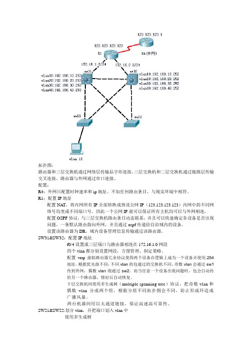
拓扑图:路由器和三层交换机通过网络层传输品字形连接,三层交换机和二层交换机通过链路层传输交叉连接。
路由器与外网通过串口连接。
配置:R4:外网只配置时钟速率和ip地址。
不加任何路由条目,与现实环境中相符。
R1:配置IP地址配置NAT,将内网所有IP全部转换成预设公网IP(123.123.123.123)内网中的不同网络号均变成不同端口号,因此一个公网IP就可以保证所有主机均可以与外网相连。
配置OSPF协议,与三层交换机路由条目动态联系,并且可以快速确定各设备是否出现问题。
一条默认路由指向外网,并且通过ospf传递给自治域内的设备。
设置该路由器为DR,域内设备管理信息传输通过该路由器。
SW31&SW32:配置IP地址f0/4设置成三层端口与路由器相连在172.16.1.0网段四个vlan都分别设置网段,方便管理、制定策略。
配置vrrp虚拟路由器冗余协议使得两个设备在逻辑上成为一个设备并使用.254地址。
根据优先级不同,不同vlan的包通过的交换机不同,奇数vlan会通过sw1传到外网,偶数vlan则通过sw2。
而当任意一个设备出现问题时,包会自动传给另一个路由器,修好后自动恢复。
下层交换机间使用多生成树(multiple spanning tree)协议,把奇数vlan和偶数vlan分成两个组,根据分组不同拓扑图会不同,防止形成环造成广播风暴。
两台机器间用以太通道链接,保证高速高可靠性。
SW21&SW22:划分vlan,并把端口划入vlan中使用多生成树功能介绍:这个拓扑中比较复杂的技术为:vrrp,MST,NA T。
1.VRRP功能介绍:虚拟路由器冗余协议(VRRP)是一种选择协议,它可以把一个虚拟路由器的责任动态分配到局域网上的VRRP 路由器中的一台。
控制虚拟路由器IP 地址的VRRP 路由器称为主路由器,它负责转发数据包到这些虚拟IP 地址。
一旦主路由器不可用,这种选择过程就提供了动态的故障转移机制,这就允许虚拟路由器的IP 地址可以作为终端主机的默认第一跳路由器。
vrrp6工作原理
VRRP6(Virtual Router Redundancy Protocol version 6)是一种网络协议,用于实现多个路由器之间的冗余和故障恢复。
它是VRRP协议的IPv6版本。
VRRP6的工作原理如下:
1. VRRP6使用一个虚拟路由器ID(VRID)来标识一个VRRP6组。
同一个组内的路由器共享同一个VRID。
2. 在VRRP6组中,一个路由器被选举为主路由器(Master),其他路由器则作为备份路由器(Backup)。
3. 主路由器负责处理组内的所有流量,而备份路由器则处于待命状态,不处理流量。
4. 主路由器通过发送VRRP6通告消息来宣告自己的存在,并通知其他路由器它是主路由器。
5. 备份路由器定期发送VRRP6请求消息来询问主路由器是否正常工作。
6. 如果主路由器无法正常工作,备份路由器中的一个将被选举为新的主路由器,并接管组内的流量处理。
7. 当主路由器恢复正常工作时,它将重新成为主路由器,备份路由
器则返回待命状态。
通过VRRP6,网络中的设备可以实现冗余和故障恢复,提高网络的可靠性和可用性。
当主路由器出现问题时,备份路由器能够自动接管流量处理,确保网络的正常运行。
vrrp实验报告原理
VRRP实验报告原理
一、实验目的
本实验旨在通过实际操作,加深对VRRP(虚拟路由冗余协议)原理的理解,掌握VRRP协议的配置和使用方法,以及实现路由器冗余备份的功能。
二、实验原理
VRRP是一种用于提高路由器可靠性和可用性的协议,它允许多台路由器共享同一个虚拟IP地址和虚拟MAC地址,其中一台路由器作为主路由器,其他路由
器作为备份路由器。
主路由器负责转发数据流量,备份路由器则处于待命状态,一旦主路由器出现故障,备份路由器会立即接管主路由器的工作,实现无缝切换,确保网络的连续性和稳定性。
三、实验步骤
1. 配置VRRP组:在路由器上创建VRRP组,指定虚拟IP地址和优先级。
2. 配置VRRP路由器:设置主备份路由器,指定VRRP组的角色和优先级。
3. 验证VRRP功能:检查VRRP路由器的状态和切换情况,验证VRRP协议是否正常工作。
四、实验结果
通过实验操作,我们成功配置了VRRP组,并设置了主备份路由器,指定了虚
拟IP地址和优先级。
在验证过程中,我们模拟了主路由器故障的情况,观察到
备份路由器能够迅速接管主路由器的工作,实现了路由器冗余备份的功能,确
保了网络的连续性和稳定性。
五、实验总结
VRRP协议是一种有效的路由器冗余备份解决方案,通过实验我们深入了解了VRRP协议的原理和工作机制,掌握了VRRP协议的配置和使用方法。
在实际网络中,合理使用VRRP协议能够提高网络的可靠性和可用性,确保网络的正常运行。
希望通过本次实验,能够加深对VRRP协议的理解,为今后的网络管理和维护工作提供参考。
Application Note 31 Virtual Router Redundancy Protocol (VRRP) andVRRP+September 20161Introduction (3)1.1Outline (3)1.2VRRP Concepts (3)1.3VRRP Definitions (4)1.4VRRP Operation (4)1.5VRRP Interoperability (4)1.6Assumptions (5)1.7Corrections (5)1.8Version and Revision History (5)2VRRP Implementation (6)2.1Using a Single VRRP IP Address (6)2.2Using a Dedicated VRRP IP Address (Hub mode or single eth port) (6)2.3Using a Dedicated VRRP IP Address (VLAN mode on multi-port) (7)3VRRP Configuration (8)3.1Configuring a Single VRRP Address (8)3.2Configuring a Dedicated VRRP IP Address (10)4VRRP+ Implementation (11)4.1Using VRRP+ (11)5VRRP+ Configuration (13)5.1Configuring the Primary (DSL) Router (13)5.2Configuring the Secondary Router (15)5.3Note about VRRP and IPsec SAs (20)6Testing (21)6.1VRRP Testing (21)6.2VRRP+ Testing (21)7Configuration Files (23)7.1Digi TransPort Configuration Files (23)7.2Digi TransPort Firmware Versions (23)1.1OutlineThis document contains information about using VRRP to achieve physical redundancy, and VRRP+ to achieve logical redundancy, with Digi TransPort Devices.1.2VRRP Concepts1.2.1VRRPVRRP is an internet standard defined by RFC2338 (/rfcs/rfc2338.html) and to quote the RFC:“VRRP specifies an election protocol that dynamically assigns responsibil ity for a virtual router to one of the VRRP routers on a LAN. The VRRP router controlling the IP address(es) associated witha virtual router is called the Master, and forwards packets sent to these IP addresses. The electionprocess provides dynamic fail over in the forwarding responsibility should the Master becomeunavailable. This allows any of the virtual router IP addresses on the LAN to be used as the default first hop router by end-hosts. The advantage gained from using VRRP is a higher availability default path without requiring configuration of dynamic routing or router discovery protocols on every end-host.”To paraphrase, VRRP works by setting up a Virtual Router - a 'floating' IP Address that clients can use as their default gateway/next hop which transparently swaps between devices in case of failure.In this case, ‘failure’ refers to the loss of the complete unit i.e. physical redundancy; it does not take into account the status of the connections behind the router.1.2.2VRRP+VRRP+ is an extension to VRRP developed by Sarian Systems Ltd before becoming part of Digi International. It allows other devices to be monitored and alter the priorities of the VRRP routers. For example, if a host becomes unreachable on the far end of a network link then the default router can be changed by adjusting the VRRP priority of the router connected to that failing link.In this case we are able to achieve logical redundancy in addition to the physical redundancy provided by basic VRRP and fail over based on the status of connections behind the router.1.3VRRP DefinitionsAs defined in RFC2338:Digi TransPort Parameters:For a full explanation of the VRRP and VRRP+ parameters please refer to the Digi TransPort Reference Manual.1.4VRRP OperationVRRP routers are organised into groups which are identified with a Group ID, all VRRP routers within the group should be able to provide the same routing and hence act as fallbacks to each other.In VRRP, routers do not communicate with each other – they only need to be aware of failures in the virtual master router. To achieve this, the virtual master router sends out multicast 'I am alive' announcements which are listened to by the virtual router backup devices in the same VRRP group.If an announcement is not received by the virtual router backup within an allotted time (usually 1 second) then it will assume control and start announcing itself as the virtual master router. If there are multiple virtual router backups then the one with the highest priority will take over.VRRP routers have a priority of which the highest number will become the virtual master router. This ranges from 1 to 255 and usual settings are to use 255 for the highest priority and 100 for the backup priority. If the current virtual master router receives an announcement from a group member with a higher priority then it will pre-empt that device and become the virtual master router.1.5VRRP InteroperabilityThe Digi TransPort VRRP implementation is fully RFC complaint and will work with other vendors’ VRRP implementations providing they are also RFC compliant.1.6AssumptionsThis guide has been written for use by technically competent personnel with a good understanding of the communications technologies used in the product, and of the requirements for their specific application. This application note applies to;Models shown: Digi TransPort WR21 (primary router) and WR44 (secondary router)Other Compatible Models: All Digi TransPort productsFirmware versions: 5.123 or later.1.7CorrectionsRequests for corrections or amendments to this application note are welcome and should be addressed to: *********************Requests for new application notes can be sent to the same address.1.8Version and Revision HistoryYou can implement VRRP on the Digi TransPort units in a number of different ways depending on requirements.2.1Using a Single VRRP IP AddressHere is an example of using a single Virtual IP address shared between two units.This will mean that the IP Address 10.1.4.254 is not assigned to any one unit, but floats between them depending on which is the VRRP master router. If both ETH0 interfaces are connected to a hub/switch along with a client, then the client will be able to always see a router at the 10.1.4.254 address.Unit_1 has a priority of 110 so should become the VRRP master router over Unit_2 which has a lower priority of 100.This is the simplest configuration but it is not generally adopted, as it means that you can only connect to the unit that is the VRRP master at any one time, which is no good for administration and monitoring of both the units.2.2Using a Dedicated VRRP IP Address (Hub mode or single eth port)A more common solution would be to have an IP address for each unit and then a third address for VRRP. Depending on the Digi TransPort model, VRRP can be implemented in different ways. If the unit has a single LAN port (e.g. WR21) then use ETH0 and ETH1 in this configuration.So as before the 10.1.4.254 VRRP address floats between the two routers on ETH1 and can be used by the clients as a default gateway, but the routers can also be reached on their own IP addresses on ETH0.If the unit has multiple ports (e.g. WR44) and is in ‘Hub m ode’ then the same applies.2.3Using a Dedicated VRRP IP Address (VLAN mode on multi-port)If a multi-port unit in ‘VLAN mode’ is used, a second uplink cable for the VRRP-addressed port will be required:NOTE:Do not try this configuration in ‘Hub mo de’ otherwise a network loop will form with undesirable consequences.This may not be practical, so an alternative solution would be to keep the unit in Hub mode and use the Group feature to make each port a member of a different hub group, but have the ETH0 and ETH1 ports in the same group for VRRP. This would require 1 uplink cable for the VRRP group.3.1Configuring a Single VRRP AddressThis section shows a single VRRP address configuration from section 2.1.For the Primary router, under Configuration - Network > Interfaces > Ethernet > ETH 0 enter the IP address and Mask to be used for VRRP.Click the Apply button.Under the VRRP sub-menu, tick ‘Enable VRRP on this interface’ and enter the VRRP Group ID and VRRP Priority.Click the Apply button and then Save.CLI commands to achieve the above:eth 0 ipaddr 10.1.41.254eth 0 mask 255.255.0.0eth 0 vrrpid 1eth 0 vrrpprio 110For the Secondary router, enter the same parameters as above, but change the VRRP Priority to 100.Go to Management - Event Log to observe VRRP starting.For example, on the Primary router you will see the following as it becomes the Virtual Router Master:15:19:53, 19 Oct 2011,ETH 0 Available,Ethernet15:19:53, 19 Oct 2011,ETH 0 VRRP BACKUP -> MASTERThe Secondary router will come up as a Virtual Router Backup:15:19:47, 19 Oct 2011,ETH 0 Out Of Service,Ethernet15:19:47, 19 Oct 2011,ETH 0 VRRP INIT -> BACKUP3.2Configuring a Dedicated VRRP IP AddressThis section shows a dedicated VRRP IP address configuration from section 2.2.Configure the same VRRP IP address and VRRP parameters as above on each unit, but for ETH1 rather than ETH0, leaving each unit’s ETH0 IP address unique to itself.NOTE: Both the ETH0 IP addresses and the ETH1 VRRP IP address should be members of the same subnet.Also, in both routers, go to Configuration - Network > Interfaces > Ethernet > ETH 0 > Advanced Make sure the device is in Port Isolate mode (click the Switch to Port Isolate if in Hub Mode).Click the Apply button and then Save.See section 6.1 for testing this setup.4.1Using VRRP+VRRP+ was developed by Sarian Systems Ltd before becoming part of Digi International. It allows VRRP to be extended to provide intelligent fail over scenarios.For example, if you have two routers that connect to the internet, a DSL router and a cellular or ISDN router that you want to use as backup.In addition to the backup router taking over if the DSL router fails completely, it is also desirable to swap over if the DSL line fails or the DSL ISP has some kind of fault which prevents access to the hosted services. To achieve this the Digi TransPort backup router is set to use VRRP+ probing to send ICMP (ping) packets to the network monitoring server.In the event of a failure of a ping, the VRRP Priority on the Digi TransPort backup router will be incremented by 20, giving it a VRRP priority of 120. This makes it higher than the priority of the primary virtual router and will cause the backup virtual router to become the VRRP Master Router and take all the traffic bound for the internet.Whilst the DSL router is unable to route traffic, the backup router will still try to ping the network monitoring server to detect when the main route becomes available again. When the VRRP+ probing routerreceives ICMP replies from the network monitoring server, the VRRP priority on the backup router is decreased by 20 returning it to 100. Network traffic then uses the main DSL router as its gateway.If the network monitoring server is behind a firewall and cannot be configured to respond to ICMP (ping) requests, this can be overcome by setting the router to probe an alternative port such as 80 (HTTP/Web) on a web server instead.In the event of VRRP+ detecting a routing failure, the traffic flow should be altered as shown:This shows the VRRP+ configuration from section 4.1. This example shows the configuration of the VRRP+ operation and does not cover the configuration of the DSL/GPRS/ISDN portion.5.1Configuring the Primary (DSL) RouterGo to Configuration - Network > Interfaces > Ethernet > ETH 0Enter the IP address and Mask to be used for Primary Router address.NOTE: There are no VRRP parameters for this interface.Click the Apply button.Go to Configuration - Network > Interfaces > Ethernet > ETH 0 > AdvancedMake sure the device is in Port Isolate mode (click the Switch to Port Isolate if in Hub Mode).Click the Apply button.Go to Configuration - Network > Interfaces > Ethernet > ETH 1 Enter the IP address and Mask to be used for VRRP:Click the Apply button.Under the VRRP sub-menu, tick ‘Enable VRRP on this interface’ and enter the VRRP Group ID and VRRP Priority, then click Apply.Click the Apply button and then save.CLI commands to achieve the above:eth 0 ipaddr 10.1.41.1eth 0 mask 255.255.0.0eth 1 ipaddr 10.1.41.254eth 1 mask 255.255.0.0eth 1 vrrpid 1eth 1 vrrpprio 1105.2Configuring the Secondary RouterGo to Configuration - Network > Interfaces > Ethernet > ETH 0Enter the IP address and Mask to be used for Primary Router address.NOTE: There are no VRRP parameters for this interface.Click the Apply button.Make sure the device is in Port Isolate mode (click the Switch to Port Isolate if in Hub Mode).Click the Apply button.Go to Configuration - Network > Interfaces > Ethernet > ETH 1Enter the IP address and Mask to be used for VRRP:Click the Apply button.Under the VRRP sub-menu, tick ‘Enable VRRP on this interface’ and enter the VRRP Group ID and VRRP Priority.Tick ‘Enable VRRP+ Probing’ and enter the following details for the ETH 1 VRRP Probe.CLI commands to achieve the above: eth 0 ipaddr 10.1.41.2eth 0 mask 255.255.0.0eth 1 ipaddr 10.1.41.254eth 1 mask 255.255.0.0eth 1 vrrpid 1eth 1 vrrpprio 100eth 1 vprobemode icmpeth 1 vprobeip 166.241.38.77 eth 1 vprobebackint 1eth 1 vprobemastint 1eth 1 vprobefailcnt 3eth 1 vprobesuccesscnt 1eth 1 vprobeadj 20eth 1 vprobeadjup ONeth 1 vprobeent eth** This should ideally be an IP address that you own and have control of. The IP address is usually a WAN address at the Head Office network.Go to Configuration - Network > IP Routing/Forwarding > Static Routes > Routes 0 - 9 > Route 0 Enter a static route to the VRRP+ probed IP address, this is required so the probing does not follow the default route.Finally, click Apply then save the configuration as power up profile 0.CLI commands to achieve the above:route 0 IPaddr 166.241.38.77route 0 mask 255.255.255.255route 0 gateway 10.1.41.1route 0 ll_ent ethSee section 6.2 for testing this setup.5.3Note about VRRP and IPsec SAsIt is quite common that the secondary router will use IPsec to create a secure tunnel into the head office network when the primary route (the red path shown above) is out of service.When the primary route is working correctly, the left router will become VRRP master again. When this happens, it is usually desirable to drop the IPsec VPN on the backup router (right) and remove the SAs associated with that tunnel.To configure removal of IPsec SAs (on the backup router) when the backup router is not VRRP master, browse to Configuration - Network > Virtual Private Networking (VPN) > IPsec > IPsec Tunnels > IPsec 0 > Advanced and put a tick in the box as shown (but for the relevant IPsec VPN):Click the Apply button and save.6.1VRRP TestingThe testing of VRRP is very simple. Start a ping going to the VRRP IP address and then disconnect the Ethernet cable from the primary router. This will cause the backup router to become the master. The following will be shown in the eventlog of the backup router (Management - Event Log):15:38:41, 19 Oct 2011,ETH 1 Available,Ethernet15:38:41, 19 Oct 2011,ETH 1 VRRP BACKUP -> MASTERWhen you reconnect the Ethernet cable back to the primary router, the backup router demotes back to being the backup and puts eth 1 out of service:15:38:56, 19 Oct 2011,ETH 1 Out Of Service,Ethernet15:38:56, 19 Oct 2011,ETH 1 VRRP MASTER -> BACKUP6.2VRRP+ TestingVRRP+ testing is a little more complicated, in this example a WR21 with an ADSL connection is the primary link and a WR44 with cellular as the backup link. Once the units are configured as above the primary router becomes the VRRP master:15:50:30, 19 Oct 2011,ETH 1 Available,Ethernet15:50:30, 19 Oct 2011,ETH 1 VRRP BACKUP -> MASTERAnd the backup router becomes the VRRP backup:15:50:32, 19 Oct 2011,ETH 1 Out Of Service,Ethernet15:50:32, 19 Oct 2011,ETH 1 VRRP MASTER -> BACKUPIn this state all internet traffic is routed to the VRRP gateway (the WR21); as with VRRP if the WR21 should fail then the WR44 becomes the VRRP master:15:52:09, 19 Oct 2011,ETH 1 Available,Ethernet15:52:09, 19 Oct 2011,ETH 1 VRRP BACKUP -> MASTERVRRP+ also tests the link to the internet; in this example ICMP is used to test the connection to a known public IP address. VRRP+ can be tested by removing the ADSL cable from the WR21 to simulate ADSL failure.WR21:15:53:37, 19 Oct 2011,PPP 1 Out Of Service,Activation15:53:37, 19 Oct 2011,PPP 1 down,LL disconnect15:53:37, 19 Oct 2011,ATM PVC 0 down,Lower layer down15:53:37, 19 Oct 2011,ADSL 0 down15:53:37, 19 Oct 2011,ADSL line: Idle15:53:37, 19 Oct 2011,ETH 1 Out Of Service,Ethernet15:53:37, 19 Oct 2011,ETH 1 VRRP MASTER -> BACKUPWR44:15:53:39, 19 Oct 2011,ETH 1 Available,Ethernet15:53:39, 19 Oct 2011,ETH 1 VRRP BACKUP -> MASTERAs you can see from this from this example as soon as VRRP Probing detects that that the known public IP address is no longer available via the WR21 it promotes the WR44 to VRRP Master and demotes the WR21 to VRRP backup. The WR44 then routes all internet traffic. As soon as the ADSL line is available and VRRP Probing can reach the public IP address it demotes the WR44 back to backup and the WR21 is master again:WR21:15:56:23, 19 Oct 2011,ETH 1 Available,Ethernet15:56:23, 19 Oct 2011,ETH 1 VRRP BACKUP -> MASTER15:56:14, 19 Oct 2011,Default Route 0 Available,Activation15:56:14, 19 Oct 2011,PPP 1 Available,Activation15:56:14, 19 Oct 2011,PPP 1 up7.1Digi TransPort Configuration FilesThis is the configuration file from the primary router – WR21:eth 0 IPaddr "10.1.41.1"eth 0 mask "255.255.0.0"eth 1 IPaddr "10.1.41.254"eth 1 mask "255.255.0.0"eth 1 vrrpid 1eth 1 vrrpprio 110def_route 0 ll_ent "ppp"def_route 0 ll_add 1This is the configuration file from the secondary router – WR44:eth 0 IPaddr "10.1.41.2"eth 0 mask "255.255.0.0"eth 1 IPaddr "10.1.41.254"eth 1 mask "255.255.0.0"eth 1 vrrpid 1eth 1 vrrpprio 100eth 1 vprobemode "ICMP"eth 1 vprobeip "166.241.38.77"eth 1 vprobebackint 1eth 1 vprobemastint 1eth 1 vprobefailcnt 1eth 1 vprobesuccesscnt 1eth 1 vprobeadj 20eth 1 vprobeadjup ONeth 1 vprobeent "ETH"route 0 IPaddr "192.32.42.133"route 0 mask "255.255.255.255"route 0 gateway "10.1.41.1"route 0 ll_ent "ETH"def_route 0 ll_ent "ppp"def_route 0 ll_add 17.2Digi TransPort Firmware VersionsThis is the firmware / hardware information from the primary router – WR21: Digi TransPort WR21-L52A-DE1-XX Ser#:293824 HW Revision: 1201a Software Build Ver5.2.15.6. Aug 17 2016 17:42:08 WWARM Bios Ver 7.56u v43 454MHz B987-M995-F80-O0,0 MAC:00042d047bc0 Power Up Profile: 0Async Driver Revision: 1.19 Int clkWi-Fi Revision: 2.0Ethernet Port Isolate Driver Revision: 1.11Firewall Revision: 1.0EventEdit Revision: 1.0Timer Module Revision: 1.1AAL Revision: 1.0ADSL Revision: 1.0(B)USBHOST Revision: 1.0L2TP Revision: 1.10PPTP Revision: 1.00TACPLUS Revision: 1.00PAD Revision: 1.4X25 Switch Revision: 1.7V120 Revision: 1.16TPAD Interface Revision: 1.12SCRIBATSK Revision: 1.0BASTSK Revision: 1.0ARM Sync Driver Revision: 1.18TCP (HASH mode) Revision: 1.14TCP Utils Revision: 1.13PPP Revision: 1.19WEB Revision: 1.5SMTP Revision: 1.1FTP Client Revision: 1.5FTP Revision: 1.4IKE Revision: 1.0PollANS Revision: 1.2PPPOE Revision: 1.0BRIDGE Revision: 1.1MODEM CC (Siemens MC75) Revision: 1.4FLASH Write Revision: 1.2Command Interpreter Revision: 1.38SSLCLI Revision: 1.0OSPF Revision: 1.0BGP Revision: 1.0QOS Revision: 1.0RADIUS Client Revision: 1.0SSH Server Revision: 1.0SCP Revision: 1.0CERT Revision: 1.0LowPrio Revision: 1.0Tunnel Revision: 1.2OVPN Revision: 1.2TEMPLOG Revision: 1.0iDigi Revision: 2.0OKThis is the firmware / hardware information from the secondary router – WR44: Digi TransPort WR44-HXT1-WE1-XX Ser#:160601 HW Revision: 7902a Software Build Ver5.2.15.6. Aug 17 2016 17:42:08 SWARM Bios Ver 6.32 v39 400MHz B512-M512-F80-O0,0 MAC:00042d027359 Power Up Profile: 0Async Driver Revision: 1.19 Int clkWi-Fi Revision: 2.0IX Revision: 1.0Ethernet Port Isolate Driver Revision: 1.11Firewall Revision: 1.0EventEdit Revision: 1.0Timer Module Revision: 1.1(B)USBHOST Revision: 1.0L2TP Revision: 1.10PPTP Revision: 1.00TACPLUS Revision: 1.00MODBUS Revision: 0.00MySQL Revision: 0.01PAD Revision: 1.4 X25 Switch Revision: 1.7 V120 Revision: 1.16 TPAD Interface Revision: 1.12 GPS Revision: 1.0 SCRIBATSK Revision: 1.0 BASTSK Revision: 1.0 PYTHON Revision: 1.0 ARM Sync Driver Revision: 1.18 TCP (HASH mode) Revision: 1.14 TCP Utils Revision: 1.13 PPP Revision: 1.19 WEB Revision: 1.5 SMTP Revision: 1.1 FTP Client Revision: 1.5 FTP Revision: 1.4 IKE Revision: 1.0 PollANS Revision: 1.2 PPPOE Revision: 1.0 BRIDGE Revision: 1.1 MODEM CC (Ericsson 3G) Revision: 1.4 FLASH Write Revision: 1.2 Command Interpreter Revision: 1.38 SSLCLI Revision: 1.0 OSPF Revision: 1.0 BGP Revision: 1.0 QOS Revision: 1.0 RADIUS Client Revision: 1.0 SSH Server Revision: 1.0 SCP Revision: 1.0 CERT Revision: 1.0 LowPrio Revision: 1.0 Tunnel Revision: 1.2 OVPN Revision: 1.2 QDL Revision: 1.0 WiMax Revision: 1.0 iDigi Revision: 2.0 OK。
VRRP配置实验一、基础知识:虚拟路由冗余协议(VRRP)与热备份路由协议(HSRP)都是一种默认网关冗余方法,它们都是让一组路由器构成一台虚拟路由器。
和HSRP不同的是,VRRP是开发的协议,而HSRP是思科专属的。
使用VRRP创建的虚拟路由器被称为VRRP组,它代表一组路由器。
在VRRP组中是通过优先级来决定主虚拟路由器的。
优先级范围:1—255。
如果优先级设置为0,那么主路由器和任何路由器将不再是VRRP组中的路由器。
(通过将优先级设置为0来让主路由器自动辞职。
)二、VRRP的配置与验证:配置主要命令:1.定义VRRP组Vrrp group-number ip virtual-ip-address2.配置指定VRRP路由器的优先级:Vrrp group-number priority priority-value3.允许主虚拟路由器失效的情况下切换到备用虚拟路由器:Vrrp group-number preempt验证命令:1.查看VRRP详细配置信息:Show vrrp all2.查看VRRP简要配置信息:Show vrrp brief3.查看VRRP接口配置信息:Show vrrp interface FastEthernet*/*三、实验:拓扑图:四、RIP路由的配置,参考:R1(config)#router ripR1(config)#ver 2R1(config)#no auto-summary地址段不连续的情况而且相隔路由设备的话最好不要开启R1(config)#network 192.168.20.0R1(config)#network 192.168.10.0五、VRRP配置主要命令:R1(config-if)#int f0/0R1(config-if)#vrrp 1 ip 192.168.10.1 //虚拟路由器ip地址R1(config-if)#VRRP 1 priority 200 //优先级200R1(config-if)#vrrp 1 preempt //是否抢占R1(config-if)#exit六、最后测试1. 将pc1的网卡设置为真机2.Tracert命令检测3.断开R1的F0/0的端口号4. 再测试。
防火墙VRRP协议安全性测试浅析VRRP(Virtual Router Redundancy Protocol,虚拟路由冗余协议)是一种容错协议,它通过把几台路由设备联合组成一台虚拟的路由设备,并通过一定的机制来保证当主机的下一跳设备(默认网关)出现故障时,可以及时将业务切换到备用设备,从而保持通讯的连续性和可靠性。
而VRRP协议自身的安全性则直接关系到系统的健壮性,本文将以我司防火墙产品为例,对VRRP协议的实现进行多维度全方位的安全性测试验证。
1. VRRP协议基础知识VRRP报文的目的是和所有VRRP路由器通告与虚拟路由器ID相关联的主路由器的优先级和状态。
VRRP包被封装在IP包中发送,它们被发送到分配给VRRP的IPv4组播地址。
1.1 MAC层字段描述DMAC:目的MAC地址,IANA为VRRP分配的目的MAC地址为01:00:5e:00:12。
SMAC:源MAC地址,VRRP使用源MAC地址为00-00-5E-00-01-{VRID}。
1.2 IP层字段描述Time to Live:TTL必须设置为255,接收TTL不等于255的数据包的VRRP路由器必须丢弃该数据包。
Source Address:使用接口的主IP地址发送数据包。
Destination Address:IANA为VRRP分配的IP组播地址为:224.0.0.18;这是一个链接本地范围组播地址,无论其TTL是多少,路由器都不能转发具有此目标地址的报文。
1.3 VRRP层字段描述1.3.1 VRRP报文格式表1-1 VRRP报文格式0 4 7 15 23 311.3.2 VRRP字段描述表1-2 VRRP字段描述1.3.3 VRRP报文示例图1-1 VRRP报文示例2. 如何进行安全性测试通过前面的讲解,可以看到对于VRRP协议每个字段都有着明确的合规性要求,但是具体到产品功能实现上是否进行了全面的校验呢?这就需要我们测试人员实际地去逐一分析测试验证。
mstp+vrrp工作原理
MSTP(Multiple Spanning Tree Protocol)和VRRP(Virtual Router RedundancyMSTP(Multiple Spanning Tree Protocol)和VRRP(Virtual Router Redundancy Protocol)是两种不同的网络协议,它们分别用于提高网络的可靠性和冗余性。
MSTP是一种用于在局域网中消除环路的协议,它通过构建多个生成树来避免网络中的环路问题。
当网络中出现故障时,MSTP可以快速切换到备份路径,保证网络的稳定运行。
MSTP还支持VLAN(Virtual Local Area Network)功能,可以将不同VLAN的数据流量隔离开来,提高网络的安全性和效率。
VRRP是一种用于实现路由器冗余的协议,它通过将多个路由器虚拟成一个主路由器来实现高可用性。
当主路由器出现故障时,VRRP会自动将虚拟路由器的角色转移到备用路由器上,从而保证网络的连续性。
VRRP还支持优先级和IP地址跟踪等功能,可以根据实际需求进行灵活配置。
综上所述,MSTP和VRRP是两种不同的网络协议,它们分别用于提高网络的可靠性和冗余性。
在实际应用中,可以根据具体需求选择合适的协议来实现网络的高可用性和稳定性。
多厂家vrrp配置交换机VRRP配置VRRP原理虚拟路由器冗余协议(VRRP)是一种标准化协议,主要用于非cisco设备厂商。
它可以把一个虚拟路由器的责任动态分配到局域网上的 VRRP 路由器中的一台。
控制虚拟路由器 IP 地址的 VRRP 路由器称为主路由器,它负责转发数据包到这些虚拟 IP 地址。
一旦主路由器不可用,这种选择过程就提供了动态的故障转移机制,这就允许虚拟路由器的 IP 地址可以作为终端主机的默认第一跳路由器。
使用 VRRP 的好处是有更高的默认路径的可用性而无需在每个终端主机上配置动态路由或路由发现协议。
VRRP 包封装在 IP 包中发送。
在一个VRRP组内的多个路由器共用一个虚拟的物理地址和I P地址,该地址被作为局域网内所有主机的缺省网关地址。
VRRP协议决定哪个路由器被激活,该被激活的路由器接收发过来的数据包并进行路由。
组内的各路由器之间交换呼叫信号,如果当前路由器变得无法使用,备用路由器将进入激活状态,接管路由任务。
VRRP配置命令:1) 华为系列交换机配置:vrrp ping-enable:根据VRRP的标准协议,备份组的虚拟IP地址是无法使用ping命令来ping通的。
此命令可以使用户能够使用ping命令来ping通备份组的虚拟IP地址。
如果需要主机可以ping通网关,则此命令必须在配置vrrp之前使能。
vrrp vrid virtual-router-ID virtual-ip virtual-address:将一个本网段的IP地址指定到一个虚拟路由器vrrp vrid virtual-router-ID priority priority-value:设置路由器在备份组中的优先级,优先级越大,越有机会成为备份组中的主设备。
vrrp vrid virtual-router-ID preempt-mode [ timer delay delay-value ]:设置路由器抢占模式。
VRRP原理与实例1.1 VRRP简介如图1-1所⽰,通常,同⼀⽹段内的所有主机上都存在⼀条相同的、以⽹关为下⼀跳的缺省路由。
当⽹关发⽣故障时,本⽹段内所有以⽹关为缺省路由的主机将⽆法与外部⽹络通信。
图1-1 局域⽹组⽹⽅案VRRP(Virtual Router Redundancy Protocol,虚拟路由器冗余协议)将可以承担⽹关功能的⼀组路由器加⼊到备份组中,形成⼀台虚拟路由器,由VRRP 的选举机制决定哪台路由器承担转发任务,局域⽹内的主机只需将虚拟路由器配置为缺省⽹关。
VRRP 是⼀种容错协议,在提⾼可靠性的同时,简化了主机的配置。
在具有多播或⼴播能⼒的局域⽹(如以太⽹)中,借助VRRP 能在某台路由器出现故障时仍然提供⾼可靠的缺省链路,有效避免单⼀链路发⽣故障后⽹络中断的问题,⽽⽆需修改动态路由协议、路由发现协议等配置信息。
1-2设备⽀持标准协议模式的VRRP:即基于RFC实现的VRRPv2 和VRRPv3。
其中,VRRPv2 基于IPv4,VRRPv3 基于IPv6。
VRRPv2 和VRRPv3 在功能实现上并没有区别,只是应⽤的⽹络环境不同,详细介绍请参见“1.2 VRRP标准协议模式”。
1.2 VRRP标准协议1.2.1 VRRP备份组简介VRRP 将局域⽹内的⼀组路由器划分在⼀起,称为⼀个备份组。
备份组由⼀个Master 路由器和多个Backup 路由器组成,功能上相当于⼀台虚拟路由器。
VRRP 备份组具有以下特点:图1-2 VRRP 组⽹⽰意图如图1-2所⽰,Router A、Router B和Router C组成⼀个虚拟路由器。
此虚拟路由器有⾃⼰的IP地址。
局域⽹内的主机将虚拟路由器设置为缺省⽹关。
Router A、Router B和Router C中优先级最⾼的路由器作为Master路由器,承担⽹关的功能。
其余两台路由器作为Backup路由器。
1. 虚拟IP备份组具有虚拟IP 地址。
vrrp的作用及master选举规则。
VRRP(Virtual Router Redundancy Protocol)是一种网络协议,用于在多个路由器中实现冗余,以提高网络的可靠性和冗余。
它使用虚拟路由器(Virtual Router)来实现多个路由器的冗余,使得在主路由器出现故障时能够无缝切换到备用路由器,保证网络的连通性。
VRRP的作用主要有以下几点:1.提高网络可靠性:通过使用多个路由器进行冗余,VRRP能够在主路由器出现故障时迅速将备用路由器接管主要的路由功能,从而保证网络的连通性,减少网络中断的风险。
2.实现负载均衡:VRRP可以配置多个虚拟路由器,这些虚拟路由器可以拥有相同的虚拟IP地址,从而将网络流量均匀地分布到各个路由器上,实现负载均衡。
3.简化网络配置:使用VRRP可以将多个路由器组成一个逻辑设备,对外表现为一个虚拟的路由器,这样可以简化网络配置,减少路由器的配置工作量。
VRRP的主选举规则如下:1. 优先级:每个VRRP路由器都有一个优先级,范围是0-255,默认值为100。
当VRRP路由器作为Master时,其他路由器的优先级越高,它被选为Master的概率越大。
2. 虚拟路由器MAC地址:VRRP中的每个虚拟路由器都有一个虚拟MAC地址,由虚拟路由器的虚拟IP地址生成,当VRRP路由器被选为Master时,它将使用虚拟MAC地址。
3. 消息优先级:VRRP路由器之间会周期性地发送VRRP消息,这些消息包括路由器的优先级、虚拟路由器的IP地址等信息。
当收到VRRP消息时,路由器将根据收到的消息中优先级的高低判断是否将对方选为Master。
主选举的过程如下:1.所有路由器发送VRRP消息,包括自己的优先级和虚拟路由器的IP 地址。
2. 所有路由器将收到的消息与自己的状态进行比较,如果收到的消息中的优先级高于自己,则将对方选为Master,更新自己的状态。
3. 如果收到的消息中的优先级与自己相同,则根据预定义的规则来决定谁将成为Master,如优先选择使用虚拟IP地址的路由器。
vrrp认证要求VRRP(Virtual Router Redundancy Protocol)是一种网络协议,用于提供网络设备冗余和故障转移能力,确保网络的高可用性和稳定性。
VRRP协议主要用于路由器、交换机等网络设备上,通过创建虚拟路由器,使多台设备共享同一个虚拟IP地址,从而实现设备之间的冗余备份和故障切换。
在部署VRRP协议时,需要遵循一些认证要求,以确保网络安全和可靠性。
以下是VRRP认证要求的相关内容:1. 认证密钥:在VRRP配置中,通常需要设置一个认证密钥,用于认证VRRP 协议的消息。
认证密钥可以有效防止恶意攻击者对VRRP协议进行篡改或伪造,提高网络的安全性。
在配置VRRP时,应当使用强密码,并且确保所有VRRP设备上的认证密钥一致。
2. 认证类型:VRRP支持多种认证类型,包括简单文本密码、MD5认证等。
在配置VRRP时,应根据实际情况选择适合的认证类型,并确保所有VRRP设备之间的认证配置一致。
3. 认证过程:在VRRP通信过程中,设备之间会定期发送VRRP协议消息,用于进行状态同步和故障检测。
认证过程中,设备会校验接收到的VRRP消息的认证信息,以确保消息的完整性和真实性。
在配置VRRP时,应确保认证过程正常运行,避免因认证失败而导致网络故障。
4. 认证日志:为了及时发现和排查VRRP认证相关的问题,建议在VRRP设备上开启认证日志功能,记录认证过程中的相关信息和事件。
认证日志可以帮助管理员追踪认证失败的原因,及时做出相应的处理和调整。
综上所述,VRRP认证要求是配置VRRP协议时的重要考虑因素,通过设置认证密钥、选择合适的认证类型、确保认证过程正常运行和记录认证日志等方式,可以提高VRRP协议的安全性和可靠性,保障网络的正常运行和数据的安全传输。
在实际部署VRRP时,应严格遵循认证要求,确保网络设备之间的VRRP通信稳定可靠。
虚拟路由冗余协议(vrrp)简介
随着Internet的迅猛发展,基于网络的应用逐渐增多。这就对网络的可靠性提出了越来
越高的要求。斥资对所有网络设备进行更新当然是一种很好的可靠性解决方案;但本着保护
现有投资的角度考虑,可以采用廉价冗余的思路,在可靠性和经济性方面找到平衡点。
虚拟路由冗余协议就是一种很好的解决方案。在该协议中,对共享多存取访问介质
(如以太网)上终端IP设备的默认网关(Default Gateway)进行冗余备份,从而在其中一
台路由设备宕机时,备份路由设备及时接管转发工作,向用户提供透明的切换,提高了网络
服务质量。
一、协议概述
在基于TCP/IP协议的网络中,为了保证不直接物理连接的设备之间的通信,必须指
定路由。目前常用的指定路由的方法有两种:一种是通过路由协议(比如:内部路由协议RIP
和OSPF)动态学习;另一种是静态配置。在每一个终端都运行动态路由协议是不现实的,大
多客户端操作系统平台都不支持动态路由协议,即使支持也受到管理开销、收敛度、安全性
等许多问题的限制。因此普遍采用对终端IP设备静态路由配置,一般是给终端设备指定一个
或者多个默认网关(Default Gateway)。静态路由的方法简化了网络管理的复杂度和减轻了
终端设备的通信开销,但是它仍然有一个缺点:如果作为默认网关的路由器损坏,所有使用
该网关为下一跳主机的通信必然要中断。即便配置了多个默认网关,如不重新启动终端设备,
也不能切换到新的网关。采用虚拟路由冗余协议 (Virtual Router Redundancy Protocol,
简称VRRP)可以很好的避免静态指定网关的缺陷。
在VRRP协议中,有两组重要的概念:VRRP路由器和虚拟路由器,主控路由器和备
份路由器。VRRP路由器是指运行VRRP的路由器,是物理实体,虚拟路由器是指VRRP协议创
建的,是逻辑概念。一组VRRP路由器协同工作,共同构成一台虚拟路由器。该虚拟路由器对
外表现为一个具有固定IP地址和MAC地址的逻辑路由器。处于同一个VRRP组中的路由器具
有两种互斥的角色:主控路由器和备份路由器,一个VRRP组中有且只有一台处于主控角色的
路由器,可以有一个或者多个处于备份角色的路由器。VRRP协议使用选择策略从路由器组中
选出一台作为主控,负责ARP相应和转发IP数据包,组中的其它路由器作为备份的角色处于
待命状态。当由于某种原因主控路由器发生故障时,备份路由器能在几秒钟的时延后升级为
主路由器。由于此切换非常迅速而且不用改变IP地址和MAC地址,故对终端使用者系统是透
明的 二、工作原理
一个VRRP路由器有的标识:VRID,范围为0-255.该路由器对外表现为的虚拟MAC
地址,地址的格式为00-00-5E-00-01-[VRID].主控路由器负责对ARP请求用该MAC地址做应
答。这样,无论如何切换,保证给终端设备的是一致的IP和MAC地址,减少了切换对终端设
备的影响。
VRRP控制报文只有一种:VRRP通告(advertisement)。它使用IP多播数据包进行
封装,组地址为224.0.0.18,发布范围只限于同一局域网内。这保证了VRID在不同网络中
可以重复使用。为了减少网络带宽消耗只有主控路由器才可以周期性的发送VRRP通告报文。
备份路由器在连续三个通告间隔内收不到VRRP或收到优先级为0的通告后启动新的一轮
VRRP选举。
在VRRP路由器组中,按优先级选举主控路由器,VRRP协议中优先级范围是0-255.
若VRRP路由器的IP地址和虚拟路由器的接口IP地址相同,则称该虚拟路由器作VRRP组中
的IP地址所有者;IP地址所有者自动具有优先级:255.优先级0一般用在IP地址所有者主
动放弃主控者角色时使用。可配置的优先级范围为1-254.优先级的配置原则可以依据链路的
速度和成本、路由器性能和可靠性以及其它管理策略设定。主控路由器的选举中,高优先级
的虚拟路由器获胜,因此,如果在VRRP组中有IP地址所有者,则它总是作为主控路由的角
色出现。对于相同优先级的候选路由器,按照IP地址大小顺序选举。VRRP还提供了优先级
抢占策略,如果配置了该策略,高优先级的备份路由器便会剥夺当前低优先级的主控路由器
而成为新的主控路由器。
为了保证VRRP协议的安全性,提供了两种安全认证措施:明文认证和IP头认证。
明文认证方式要求:在加入一个VRRP路由器组时,必须同时提供相同的VRID和明文密码。
适合于避免在局域网内的配置错误,但不能防止通过网络监听方式获得密码。IP头认证的方
式提供了更高的安全性,能够防止报文重放和修改等攻击。
三、 应用实例
最典型的VRRP应用:RTA、RTB组成一个VRRP路由器组,假设RTB的处理能力高于
RTA,则将RTB配置成IP地址所有者,H1、H2、H3的默认网关设定为RTB.则RTB成为主控路
由器,负责ICMP重定向、ARP应答和IP报文的转发;一旦RTB失败,RTA立即启动切换,成
为主控,从而保证了对客户透明的安全切换。
在VRRP应用中,RTA在线时RTB只是作为后备,不参与转发工作,闲置了路由器RTA
和链路L1.通过合理的网络设计,可以到达备份和负载分担双重效果。让RTA、RTB同时属于
互为备份的两个VRRP组:在组1中RTA为IP地址所有者;组2中RTB为IP地址所有者。将
H1的默认网关设定为RTA;H2、H3的默认网关设定为RTB.这样,既分担了设备负载和网络流
量,又提高了网络可靠性。
VRRP协议的工作机理与CISCO公司的HSRP(Hot Standby Routing Protocol)有许
多相似之处。但二者主要的区别是在CISCO的HSRP中,需要单独配置一个IP地址作为虚拟
路由器对外体现的地址,这个地址不能是组中任何一个成员的接口地址。
使用VRRP协议,不用改造目前的网络结构,限度保护了当前投资,只需最少的管理
费用,却大大提升了网络性能,具有重大的应用价值。