1 PGREM3D Parallel Groundwater Transport and Remediation codes
- 格式:pdf
- 大小:46.62 KB
- 文档页数:6

精心整理1、怎样查看模型?答:plotgrid可以查看网格,plotgridnum可以查看节点号。
2、请问在圆柱体四周如何施加约束条件?答:可以用fix...rancylinderend1end2radiusr1cylinderend1end2radiusr2not,其中r2<r1,其实就是选择range的时候选两个圆柱的差,即得到边界。
命令流如下:fixxrangeend1100end2140rad1end1100end2140rad13、怎么能把一个PLOT的图像数据导出来以便用其他软件绘图?答:用setlogon命令,把数据导出来,转到excel里处理一下,然后用surfer或者什么作图软件绘制就行了。
4、用命令建立模型后,如何显示点的坐标?答:使用ploblogrogpnumon命令5、关于gauss_dev对性质进行高斯正态分布的问题?答:根据手册上的说明:下面的命令设定一个平均摩擦角为40度,标准方差是±5%。
则命令如下:propfriction40gauss_dev2问题:请问gauss_dev2中的2是如何计算的?如果把±5%改为±10%,则命令应如何写?40×5%=26、reflect问题问:genzoneradbrick&p0(0,0,0)p1(10,0,0)p2(0,10,0)p3(0,0,10)&size3,5,5,7&ratio1,1,1,1.5&di m142fillplotsurfgenzonereflectdip0dd90(对xy面做镜像)genzonereflectdip90dd90(对yz面做镜像)(1)dd表示y轴正向顺时针到那条射线的夹角,dip表示对称参照面与xy平面的夹角,对称参照面与xy平面的夹角在xy平面的投影是一条射线。
首先应该按照dd的方向大体确定这个面的朝向,dd指的是从y轴正方向按顺时针(clockwise)方向转向所要确定面的法线方向在xy平面上的投影的夹角,然后再确定dip,dip指的是从xy平面转向所要确定的平面的角.(及z轴负方向转过角度)(2)命令:reflectnormalxyzoriginxyz(根据法线和过一点建的面)最常用,至于实际使用过程中有人问道:normal-100与normal100的区别,我试过两者的效果是一样的,没区别,虽然方向不同,但表达的是同一个面。

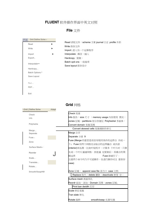
FLUENT 软件操作界面中英文对照File 文件Read 读取文件:scheme 方案journal 日志 profile 外形 Write 保存文件 Import :进入另一个运算程序 Interpolate :窜改,插入Hardcopy :复制,Batch opti ons —组选项Save layout 保存设计 Grid 网格| F 屆 Grid Define Solve i-Read► Write►Import ► Export-, Interpolate —Hardcopy...Batch Options.^Save LayoutRun...RSF...ExitDefine Models模型:solver解算器Pressure based 基于压力Den sity based基于密度末解用丁 pressure based,雀改用Censity based 岀观不苻合秦相36的摄不,请甸pres 羊WE base d Al density based 慎仆则迢.41刊卜 IS 况?北外.血OC ・EHU ^ cotipled >(/^ ptiaw ccupl ed simple 可这孔 & pimple ijEpiso 逞划.--■轟=Sortg 冲-丸布时制* ^jfe-5-6 1844DOden ba&ed 亘工F 吋.压聲血ptessurt ba$«i 适可于那可乐册斤"dens Ply based 把丸“河悴掏t :至殳嗟之一.刑牛可爪門d 的创R 监當歎1一,般如人锻暮叫人丄有用 轴怀,火薩墟迭牛才H5)-0 程:yje8D8-丸布门 1叫;20GS-3-7 10-2ODQ歆;I :谢PrflSsdrfl-Bawd Soker ^Fluflnt 它星英于压力快的束解孤便丹的圮压力修止畀法"求释旳控制片悝足标联式的,擅K 家鮮不町压縮舐Mb 对于町压砂也可旦索麟;Fk«nl 6-3 tl 前的I 板』冷孵臥 B fjS4^r«^at«d &Olvar fli Cfruptod Solvtr,的实也fltje Pr#4iurft-ea5<KJ ScFvAi 约两种虽幵方ib应理拈Fluent 氐J 眇坝犢型小的.它拈垒于曲喪红旳求聲塞,最辑的出H .也桿 艮先■那式的.丰誓■載密式冇Roz AU$hk>谏方法的初和&让Fhwrt 耳有比我甘的求IT 可压胃(说 劫謹力,們耳帕榕式淮冇琴加IF 科限闾辉,倒比还丰A 完荐匚Coupted 的算送t 对子慨站何Hh 地们足便用円匕口讷油皿购 加£未处為 性上世魅端计棒低逢刈趾.擁说的DansJty-Bjiwd Solver F ft St SiMPLEC, P 怡DE 些选以的.闪为進些ffliQl ;力修止鼻袪・不金在这种类崖的我押■中氏现泊I 建址祢匹足整用Fw»ur 护P.sed Solver 堺决昧的利底*implicit 隐式, explicit 显示Space 空间:2D , axisymmetric (转动轴), axisymmetric swirl (漩涡转动轴);Time 时间 :steady 定常,unsteady 非定常 Velocity formulatio n 制定速度: absolute 绝对的;relative 相对的Gradient option 梯度选择:以单元作基础;以节点作基础;以单元作梯度的最小正方形。
RES3DINV ver. 2.16for Windows 98/Me/2000/NT/XPRapid 3D Resistivity & IP inversionusing the least-squares method(For 3-D surveys using the pole-pole, pole-dipole, dipole-dipole, rectangular, Wenner, Wenner-Schlumberger and non-conventional arrays) On land, underwater and borehole surveysGeoelectrical Imaging 2D & 3DGEOTOMO SOFTWAREFebruary 2007This software is distributed by :Geotomo Software,5 Cangkat Minden Lorong 6,Minden Heights, 11700 Gelugor,Penang,MALAYSIATel : +60 4 6574525, Fax : +60 4 6588437email : geotomo@.myInternet : Table of ContentsTopic Page No.1 Introduction 12 Computer system requirements 23 Copy protection 44 Theory 55 Disk contents 76 Using the program 87 File operations 98 Change program settings 119 Inversion of data1710 Display results1911 Topography 2412 Help 2413 Some field examples 2414 Trouble shooting 30Acknowledgements 30References 31Appendix A : 3D surveys with the pole-pole array 33Appendix B : 3D surveys with the pole-dipolearray 37 Appendix C : 3D surveys with the dipole-dipolearray 39 Appendix D : Fixing Resistivities 40Appendix E : IP data inversion 42Appendix F : Speed of graphics display 45Appendix G : Non-uniform survey grids 46Appendix H : The equatorial dipole-dipole(rectangular) array 48 Appendix I : Export model to Rockworks andSlicer/Dicer format 49 Appendix J : Disabling computer powermanagement and screen saver 52 Appendix K : Inversion of large data sets,hard-disk file format andrecommended PC systems 53Appendix L : Non-conventional or general arrays 55Appendix M : Using more than 1 GB RAM 56Appendix N : 3-D underwater surveys 59Appendix O : Cross-borehole data inversion 62Appendix P : Non-rectangular (trapezoidal)survey grids 66 Appendix Q : Special topography informationfor mineral exploration surveys 69Appendix R : Processor Optimisations 70Appendix S : Batch mode inversions 71Disclaimer 73Support 73What’s New 74Notice of CopyrightRES3DINV is copyrighted by (C) Geotomo Software, 2000-2007. All rights reserved. No part of this document may be reproduced without written permission of Geotomo Software.1 IntroductionRES3DINV is a computer program that will automatically determine a three-dimensional (3-D) resistivity model for the subsurface using the data obtained from a 3-D electrical imaging survey (Li and Oldenburg 1992, White et al. 2001). Ideally, the electrodes for such a survey are arranged in a rectangular grid (Figure 1). However, in practice (depending on the available equipment, surface topography, survey time and budget), different types of survey procedures have been used. More details on the practical use of the pole-pole, pole-dipole and dipole-dipole arrays for 3D surveys are given in Appendices A, B and C, as well as in the free Tutorial Notes on electrical imaging (Loke 2002). The most common arrays used for 3-D surveys are the pole-pole, pole-dipole and dipole-dipole arrays. Other arrays might not provide sufficient data coverage for a full 3-D inversion. On a computer with 1.5 GB RAM, this program can handle survey grids with about up to 77 by 77 (or about 6000) electrodes! On a modern Pentium 4 based microcomputer, the data inversion takes less than a minute for small surveys with 100 electrodes in a flat area, to a day for extremely large surveys with 6000 electrodes in rugged terrain.Figure 1. A schematic diagram for one possible layout for a 3-D survey.2 Computer system requirementsRES3DINV is a 32-bit program that will run under Windows 98/Me/NT/ 2000/XP. You will need a Pentium (III or 4) or compatible based microcomputer to run this program. The minimum amount of RAM required is 256 MB, but 1024 MB or higher is recommended. You will also need at least 1024 MB of free hard-disk space that the program can use to store temporary swap files. If you have more than one hard-disk drive, the program will automatically select the drive with the largest amount of free space as the drive to store the swap files. This is a 32-bit Windows program that can access up to 4 gigabytes of memory. The more RAM and free hard-disk space you have, the larger is the data set that you can process with this program.It is also recommended that you use the 1024 by 768 (15 inch LCD monitors), or the 1280 by 1024 (for 17 and 19 inch monitors), or the 1600 by 1200 (20 inch or larger) with 256 (or higher) colours graphics mode. If the graphics appear to be rather slow on your computer, please refer to Appendix F.There should not be any background programs running (such as word processors, CAD programs) when executing the RES3DINV program. Please shut down the other programs to free the memory for this program. This will reduce memory to hard disc swapping that slows down the program. In Windows 98/Me/NT/2000/XP, the active programs are usually listed on the Start bar at the bottom of the screen.If you had purchased the software with a CD, the following setup manager should be automatically displayed when you insert the CD.Click the appropriate item in order to install RES2DINV program; followed by the RES3DINV, RES2DMOD and RES3DMOD programs. If you have the Keylok USB dongle, click on the ‘Keylok USB Driver’ to install the driver for the dongle. Select the ‘Keylok Parallel Port Driver’ only if you have the parallel port dongle.If you had downloaded the programs from the Internet, you will need to install the programs manually.The RES3DINV package comes in a single compressed installation file SETUP.EXE. It is a Windows based installation program that will install the program files. In Windows, click Start, and then Settings followed by Control Panel. Then click the icon to Add/Remove programs. After that, navigate to the folder where the SETUP.EXE file is located.For the full version of this software, it is necessary to install a system driver for the dongle. If you need to install the driver manually, follow the steps below. a). For users with the Keylok keyPlease run the INSTALL.EXE program in the found in the KEYLOK_SYSTEM_DRIVER folder in the CD. For the USB key, you will need to use the INSTALL /B command line. This program will install the appropriate driver for your operating system into your computer hard disc. More information about the system driver can be obtained at the following web site : Vista: For Windows Vista, you need to use the driver found in the InstallVistaUSB.zip file in the “KEYLOK_SYSTEM_DRIVER\Vista Driver” folder in the CD provided. The instructions are given in the “To Install USB Dongle on Vista.pdf” file.b). For users with the Rainbow Technologies Sentinel SuperPro key This is an older key that is no longer distributed with the software. However, current updates to the software will still recognize this key. If you are still using the key, please refer to the RES2DINV manual or the following web site : .In Windows 98/Me/NT/2000/XP, a Recycle Bin program is sometimes used to save recently deleted files. This feature might prove to be a nuisance when inverting very large data sets as the program uses a number of temporary files. Although the program deletes the files, they might end up in the Recycle Bin, and quickly fill up your hard disc! The RES3DINV program will, by default, use the hard disc partition with the largest amount of free space as the buffer drive. It is recommended that you disable the Recycle Bin for this drive. This can be done by clicking the Recycle Bin icon with the right mouse button, and then click the Properties option. You can then configure the settings for each hard disc drive.It is recommended that you remove the CD-ROM disc, if present, from the CD-ROM drive when using this program. Due to the multi-tasking nature of the Windows operating system, sometimes the program on the disc might belaunched while RES3DINV is busy inverting a large data set! It is also recommended that you disable the computer power management functions (in Windows as well as in the system CMOS setting) and the Windows Screen Saver program (in the Display Settings function within the Control Panel). Please refer to Appendix J for more details.For all versions of Windows, it is recommended that you run the SCANDISK program occasionally to check the condition of the hard disc, and also the defragmentation program to reduce file fragmentation. Since RES3DINV is a Windows based program, all Windows compatible graphics cards or printers are automatically supported. It has been tested with video screen modes of up to 1600 by 1200 pixels and 16 million colours.3 Copy protectionThe program uses a USB hardware key (dongle) for copy protection. Without the dongle, you can use the program to invert data sets with up to 64 electrodes (with a limit of 3 iterations in the inversion routine). If you had purchase the 2D resistivity/IP inversion program (RES2DINV) only, you can process data sets with up to 170 electrodes (with a limit of 5 iterations) using the dongle provided. In both cases, topographic modelling cannot be carried out. With a dongle that also has the RES3DINV software license, the restrictions are removed and the maximum number of electrodes the program allows is about 6000 electrodes for a computer with about 2GB RAM. This corresponds to a 77 by 77 electrodes survey grid that is much larger than those used in most field surveys.Earlier versions of this software were distributed with a dongle that is attached to the parallel printer port of your computer. The program should be able to detect the dongle if the parallel printer port follows the IBM PC specifications. If it is unable to find the dongle, the printer port is not completely IBM PC compatible. In this case, after connecting the dongle to the computer, connect a printer to the other end of the dongle. Turn on the printer and print out something, for example your AUTOEXEC.BAT file, to confirm that the printer port is working. Leave the printer on, and then try to run the RES3DINV.EXE program again. If you are still not able to solve the problem, please contact the Rainbow Technologies or the Keylok companies by email.Many new notebook computers do not have a parallel port. If you have the parallel port type of dongle, it is recommended that you exchange it with a USB dongle. Please contact geotomo@.my on the procedure to exchange the dongle.4 TheoryThe inversion routine used by the program is based on the smoothness-constrained least-squares method (deGroot-Hedlin and Constable 1990, Sasaki 1992). A new implementation of the least-squares method based on a quasi-Newton optimisation technique (Loke and Barker 1996) can also used. This technique can be more than 10 times faster than the conventional least-squares method for large data sets and requires less memory. The smoothness-constrained least-squares method is based on the following equation(J T J + u F)d = J T g(1)where F = f x f x T + f z f z Tf x = horizontal flatness filterf z = vertical flatness filterJ = matrix of partial derivativesJ T = transpose of Ju = damping factord = model perturbation vectorg = discrepancy vectorOne advantage of this method is that the damping factor and flatness filters can be adjusted to suit different types of data.In this program, you can also use the conventional Gauss-Newton method that recalculates the Jacobian matrix of partial derivatives after every iteration (Loke and Dahlin 2002). It is much slower than the quasi-Newton method, but in areas with large resistivity contrasts of greater than 10:1, it gives slightly results. A third option in this program is to use the Gauss-Newton method for the first 2 or 3 iterations, after which the quasi-Newton method is used. In many cases, this provides the best compromise.Besides the above smoothness-constrain method, other types of inversion methods are also available. The user can choose a method that will apply the smoothness-constrain directly on the model resistivity values. This method will produce an optimally smooth model (see section 8). On the other extreme, a robust model inversion method is also available which tends to produce models with sharp boundaries. The choice of inversion method to use should be guided by the nature of the known geology of the survey area.The inversion program divides the subsurface into a number of small rectangular prisms, and attempts to determine the resistivity values of the prisms so as to minimise the difference between the calculated and observed apparent resistivity values. One possible arrangement used by Loke and Barker(1996) is shown in Figure 2a. Here, each block in the top layer has an electrode in each corner. Besides this basic arrangement, two other arrangements are supported by the program. One alternative is to divide the blocks in the top few layers by half in the horizontal directions only (Figure 2c). The third alternative is to divide the layers by half in the vertical direction as well (Figure 2b). Since the resolution of the resistivity method decreases rapidly with depth, it has been found that subdividing the blocks is only beneficial for the top two layers only. In many cases, subdividing the top layer only is enough. By subdividing the blocks, the number of model parameters and thus the computer time required to invert the data set can increase dramatically.Figure 2. The models used in the inversion. (a) Standard model where the widths of the rectangular blocks are equal to the unit electrode spacings in the x- and y-directions. (b) A model where the top few layers are divided by half, both vertically and horizontally, to provide better resolution. (c) A model where the model blocks are divided in the horizontal directions but not in the vertical direction.The optimisation method tries to reduce the difference between the calculated and measured apparent resistivity values by adjusting the resistivity of the model blocks. A measure of this difference is given by the root-mean-squared (RMS) error. However the model with the lowest possible RMS error can sometimes show large and unrealistic variations in the model resistivity values and might not always be the "best" model from a geological perspective. In general the most prudent approach is to choose the model at the iteration after which the RMS error does not change significantly. This usually occurs between the 4th and 5th iterations.5 Disk contentsThe package containing the program should have the following files :RES3DINV.EXE Main inversion programROOTS7.DAT A small field data set with a 7 by 7 survey grid. SEPTIC.DAT A field data set from a survey over a septic tankusing an 8 by 7 grid.PIPE3D.DAT Data from a field survey over an undergroundpipe with an 8 by 9 grid.GRID7X7.DAT A synthetic data set with a 7 by 7 grid with all thepossible measurements. (Pole-pole array).BLK15PPL.DAT A synthetic data set with a 15 by 15 grid.(Pole-pole array).BLK15PDP.DAT A synthetic data set with a 15 by 15 grid.(Pole-dipole array).BLK15DDP.DAT A synthetic data set with a 15 by 15 grid.(Dipole-dipole array).MODEL3IP.DAT An example data file with resistivity and IP data. GRID8X8.DAT A small synthetic data set with an 8 by 8 grid.(Pole-pole array).MOD3DFIX.DAT An example data file with where the resistivity ofa section of the model is fixed by the user. BLOCK26W.DAT Example data set for the Wenner arrayBLOCK26S.DAT Example data set for the Wenner-SchlumbergerarrayBLOCK11T.DAT Example input data file with topography.RES3DINV.HLP Windows help file for the program.T Support file for help file.Depending on the type of field equipment you are using, the manufacturer of the equipment will probably also supply you with supplementary programs andexample files to convert the raw data files obtained with the instrument into the format required by this program.6 Using the programAfter installing the program, just click the RES3DINV icon to start the program. The program will first check the computer system to ensure that it has the necessary resources that this program requires. It will check for the available memory and hard-disk space. If the program displays a warning, you should quit from the program and make the necessary changes. After checking the computer configuration, the program will then display the following Main Menu bar near the top of the screen.You can select an option by clicking it with the mouse cursor. If this is the first time you are using the program, try reading in one of the smaller files such as ROOTS7.DAT provided with the program. Click the File choice, followed by the “Read in data file” submenu choice. After that, if necessary, navigate to the subdirectory where the RES3DINV program is installed. After reading in the file, go to the “Inversion” option, and then choose the “Carry out inversion” option. The inversion subroutine will start. Wait for a few minutes for the data to be inverted. If you need to stop the inversion routine at any time, just press the “Q” key and wait for a short while. By default, the program will carry out 6 iterations that can be increased if necessary.After the inversion process has been completed, click the “Display” and then the “Display inversion model” suboption. You will then be asked to select the iteration number, type of model slice (horizontal or vertical) and type of contour intervals. After you have made the appropriate choices, the program will then display the model slices.The following sections will describe the different menu options in more detail.7 File operationsWhen you select the “File” option, the following menu choices are displayed.Read data file - When you select this option, the list of files in the current directory which has an extension of DAT will be displayed. It is assumes that the files follow the format required by this program. If not, you have to convert the raw data files using the conversion program for the particular resistivity meter system. You can use the mouse or keyboard to select the appropriate file, or to change the subdirectory.The apparent resistivity values must first be typed into a text file. You can use any general purpose text editor, such as the Windows NOTEPAD program. The data are arranged in an ASCII delimited manner where a comma or blank space or LF/CR is used to separate different numerical data items. The program requires the data to be arranged in a certain format. If there is a problem in running this program, one possible cause is that the input data were arranged in a wrong format. The format of the input data file is as follows using the ROOTS7.DAT file as an example :-ROOTS7.DAT file Commentsgarden-square-0.5m | Title7 | x grid size7 | y grid size0.5 | x unit electrode spacing0.5 | y unit electrode spacing2 | array type, enter 2 for pole-pole467 | Number of datum points0.00 0.00 0.50 0.00 350.46 | For each datum point, enter0.00 0.00 1.00 0.00 398.05 | x- and y- location of current elec., x- and y- 0.00 0.00 1.50 0.00 424.08 | location of potential electrode, apparent0.00 0.00 2.00 0.00 413.83 | resistivity value0.00 0.00 2.50 0.00 373.76 |. | Repeat for all datum points. |0 | Followed by a few 0'sIn the local coordinate system used, the top-left electrode is located at (0.0,0.0). For the pole-dipole array, the x- and y- locations of the C1 electrode, followed by the x- and y- locations of the P1 electrode and then similar data for the P2 electrode are given. The file BLK15PDP.DAT is an example data file with the pole-dipole array. Note that the array type number for this array is 6.For the dipole-dipole array, the x-and y-locations of the C1 electrode, followed by the x- and y- locations of the C2 electrode, followed by the x- and y-locations of the P1 electrode and then similar information for the P2 electrode are given. The file BLK15DDP.DAT is an example data file with the dipole-dipole array. Note that the array type number for this array is 3.If the survey data has topography, the elevation of each electrode in the grid is entered in the data file after the data for the apparent resistivity measurements. The data file BLOCK11T.DAT is an example with topography which has an 11 by 11 grid of electrodes. The bottom part of the file with comments are given below.BLOCK11T.PPL file Comments8.000 10.000 10.000 10.000 113.3131 | Last two resistivity9.000 10.000 10.000 10.000 102.7262 | datum pointsTopography | Word indicates topography present2 | Type of x- and y- coordinate0.00 0.00 0.00 -0.50 -1.00 -1.50 -1.00 -0.50 0.00 0.00 0.00 | Height of electrodes in0.00 0.00 0.00 -0.50 -1.00 -1.50 -1.00 -0.50 0.00 0.00 0.00 | arranged row by row.0.00 0.00 0.00 -0.50 -1.00 -1.50 -1.00 -0.50 0.00 0.00 0.00 |0.00 0.00 0.00 -0.50 -1.00 -1.50 -1.00 -0.50 0.00 0.00 0.00 |0.00 0.00 0.00 -0.50 -1.00 -1.50 -1.00 -0.50 0.00 0.00 0.00 |The word “Topography” must be entered in the file immediately after the last apparent resistivity datum point. Next, the value “2” in the above example indicates that the x-and y-coordinates given earlier are distances along the ground surface and not the true horizontal distances. This is probably the normal case where a cable with a constant separation between the takeouts is used. If a value of “1” is given, it indicates that the x- and y- coordinates givenearlier are the true horizontal distances. Next the height of each electrode in the gird is given, row by row in the x-direction. For example, the values in the first row are the heights of the electrodes in the line at y equals to 0 metres. In this example, since there are 11 electrodes in the x-direction, there are 11 values in each row. This is followed by the heights for the second row of electrodes, and similarly for all the rows.If the data set contains topography, the inversion subroutine will automatically incorporate the topography into the inversion model by using the finite-element method (Silvester and Ferrari 1990).Edit data file - This option will call up a text editor which you can use to edit the data file.Import data in .....format : This program also allows you to run other programs to convert data arranged in a propriety format into the format required by this program. This program is usually supplied by the manufacturer of the resistivity meter system you are using.8 Change program settingsThe program has a set of predefined settings for the damping factors and other variables that generally gives satisfactory results for most data sets. However, in some situations, you might get better results by modifying the parameters which control the inversion process. When you select this option, the following menu is displayed.When you select the "Inversion parameters" suboption, the following dialog box is displayed. To change a particular setting, move the mouse cursor to the appropriate box and then just click it. Where appropriate, type in the requiredInitial Damping Factor and Minimum Damping Factor- In this section, you can set the initial value for the damping factor in equation (1), as well as the minimum damping factor. If the data set is very noisy, you should use a relatively larger damping factor (for example 0.3). If the data set is less noisy, use a smaller initial damping factor (for example 0.1).The inversion subroutine will generally reduce the damping factor in equation (1) after each iteration. However, a minimum limit for the damping factor must be set to stabilise the inversion process. The minimum value should usually set to about one-fifth to one-fifteenth of the value of the initial damping factor.Directly smooth model resistivity - The least-squares formulation used in equation (1) applies a smoothness constraint on the model perturbation vector d only, and not directly on the model resistivity values. In most cases, it will produce a model with a reasonably smooth variation in the resistivity values. In some cases, particularly for very noisy data sets, better results might be obtained by applying a smoothness constraint on the model resistivity values as well. The resulting least-squares equation is given by(J T J + u F)d = J T g - u Fr(2) where r is a vector containing the logarithm of the model resistivity values. While for the same damping factors this will usually produce a model with a larger apparent resistivity RMS error, this modification will ensure that the resulting model shows a smooth variation in the resistivity values.Line search on every iteration - The inversion routine determines the change in the model parameters by solving equation (1). Normally the parameter change vector d will result in a model with a lower RMS error. In the event that the RMS error increases, you have two options. This option enables you to perform a line search using quartic interpolation (Fletcher 1987) to find the optimum step size for the change in the resistivity of the model blocks. This will usually give the optimum step size, but will require at least one forward modelling computation per iteration. In some cases, the extra forward computation could be worthwhile if it reduces the number of iterations needed to bring the RMS error down to an acceptable level.This setting will only affect the inversion process for the third iteration onwards. For the first two iterations, where the largest change in the RMS error usually occurs, the program will always carry out a line search in an attempt to find the optimum step size to further reduce the RMS error.Minimum % RMS change for line search - The line search method used can estimate the expected change in the apparent resistivity RMS error. If the expected change in the RMS error is too small, it might not be worthwhile to proceed with the line search to determine the optimum step size for the model parameter change vector. Normally a value between 0.1 and 1.0 % is used. Thickness of first layer - This give the ratio of the thickness of the first model layer to the smallest unit electrode spacing. For the pole-pole array, this is set at 0.70 times the unit electrode spacing. For other arrays, the thickness of the first layer will be adjusted according to the depth of investigation of the array. Factor to increase layer thickness - Since the resolution of the resistivity method decreases with depth, normally the thickness of the model layers are also increased with depth. By default, a factor of 1.15 is used to increase the thickness of the model layers. In this case, the thickness of each subsequent layer increases by 15%. However, you can modify this factor within a limited range. Normally, a value of between 1.05 to 1.25 is used.Half Size Layer Option - This allows you to use a model where the widths and thickness of the top few layers are divided by half (see Figure 2 in the ‘Theory’ section). Here you can choose the number of layers which are to be subdivided, and also whether to subdivide them in the vertical direction as well (Figure 2b). You can also adjust the flatness filter damping factor for these layers. It has been found that the smaller the model blocks, the greater is the potential oscillation in the model values after inversion, especially for noisy data sets. To reduce the oscillations, you can use a slightly larger damping factor, for example 1.10, for these layers.Number of iterations - This allows the user to set the maximum number of iterations for the inversion routine. By default the maximum number of iterations is set to 6. For most data sets, this is probably sufficient. When the inversion routine reaches this maximum limit, it will ask the user for the number of additional iterations if you wish to continue with the inversion process. It is usually not necessary to use more than 10 iterations.Number of iterations to recalculate Jacobian - In the Gauss-Newton method, the Jacobian matrix is recalculated after each iteration, whereas in the quasi-Newton method the Jacobian matrix is never recalculated but estimated after each iteration (see ‘Theory’ section). The fastest method is to use the quasi-Newton method to estimate the Jacobian matrix (Loke and Barker 1996). In this case, put a value of 0 in the dialog box. This might be a good alternative to use in the field where a slower laptop computer with more limited memory is frequently used. The most accurate and slowest method is to recalculate the Jacobian matrix after every iteration. This requires a fast computer with preferably at least 32 megabytes of RAM, and about 256 megabytes free hard disc space for very large data sets. To choose this method, just put a very large value (for example 20) into the box. A third alternative is to recalculate the Jacobian matrix for the first few iterations only, and use the quasi-Newton updating method for subsequent iterations. The largest changes in the Jacobian matrix usually occurs in the first few iterations. So in many cases, a limited recalculation of the Jacobian matrix gives the best compromise between speed and accuracy. By default, the program will recalculate Jacobian matrix for the first 3 iterations only. However, the default settings can be changed by the user in this menu option. The quasi-Newton option is useful to get a quick look at the results, particularly in the field during the course of a survey using a laptop computer. Another situation where this should be used is when you want to remove the bad data points using the RMS Errors Statistics method (see the ‘Display’ section). For the final model, it is best to use the limited recalculation option on a faster desktop computer with more RAM and free hard disc space. In areas with large resistivity contrasts, where the largest apparent resistivity value is more than 10 times the smallest value, recalculating the Jacobian matrix produces models with boundaries which are sharper than those produced by the quasi-Newton method.Convergence limit - This sets the lower limit for the relative change in the RMS error between 2 iterations. By default, a value of 5% is used. In this program the relative change in the RMS error, rather than an absolute RMS value, is used to accommodate different data sets with different degrees of noise present.。


1 总则1.0.1 为了在地基基础设计中贯彻执行国家的技术经济政策,做到安全适用、技术先进、经济合理、确保质量、保护环境,制定本规范。
1.0.2 本规范适用于工业与民用建筑(包括构筑物)的地基基础设计。
对于湿陷性黄土、多年冻土、膨胀土以及在地震和机械振动荷载作用下的地基基础设计,尚应符合国家现行相应专业标准的规定。
1.0.3 地基基础设计,应坚持因地制宜、就地取材、保护环境和节约资源的原则;根据岩土工程勘察资料,综合考虑结构类型、材料情况与施工条件等因素,精心设计。
1.0.4 建筑地基基础的设计除应符合本规范的规定外,尚应符合国家现行有关标准的规定。
2 术语和符号2.1 术语2.1.1 地基Subgrade, Foundation soils支承基础的土体或岩体。
2.1.2 基础Foundation将结构所承受的各种作用传递到地基上的结构组成部分。
2.1.3 地基承载力特征值Characteristic value of subgrade bearing capacity由载荷试验测定的地基土压力变形曲线线性变形段内规定的变形所对应的压力值,其最大值为比例界限值。
2.1.4 重力密度(重度)Gravity density, Unit weight单位体积岩土体所承受的重力,为岩土体的密度与重力加速度的乘积。
2.1.5 岩体结构面Rock discontinuity structural plane岩体内开裂的和易开裂的面,如层面、节理、断层、片理等,又称不连续构造面。
2.1.6 标准冻结深度Standard frost penetration在地面平坦、裸露、城市之外的空旷场地中不少于10年的实测最大冻结深度的平均值。
2.1.7 地基变形允许值Allowable subsoil deformation为保证建筑物正常使用而确定的变形控制值。
2.1.8 土岩组合地基Soil-rock composite subgrade在建筑地基的主要受力层范围内,有下卧基岩表面坡度较大的地基;或石芽密布并有出露的地基;或大块孤石或个别石芽出露的地基。
ELEMS1、LINK1 2-D杆件 (7)输入资料 (7)输出资料 (8)LINK1利用项次和顺序号码方法将ESOL、ETABLE的结果制成表格的指令参数 (9)2、PLANE2,2-D 6节点三角形单元单元 (10)PLANE2输入数据 (10)输出数据 (11)M ISCELLANEOUS E LEMENT O UTPUT (12)PLANE2I TEM AND S EQUENCE N UMBERS FOR THE ETABLE AND ESOL C OMMANDS (12)3、BEAM3-2D弹性梁 (12)输入总结 (13)单元输出定义 (14)BEAM3(KEYOPT(9)=0)利用项次和顺序号法将ESOL、ETABLE制成表格的指令参数 (15)假设与限制 (20)4、............................................................................................................................ BEAM4-3D弹性梁 (21)单元描述 (21)7、COMBIN7-外卷的结合点 (22)单元描述 (22)8、LINK8(三维,承受轴向拉伸、压缩) (23)单元描述 (23)10、LINK10-3D、2N,仅承受拉力或者压力的杆 (23)11、LINK11-3D、2N线性激励 (24)12、CONTAC12-2D 点点接触 (24)14、COMBIN14-弹簧-阻尼单元 (25)单元描述 (25)单元数据输入 (26)单元输出定义 (26)单元利用项次和顺序号方法将ESOL、ETABLE的结果制成表格的指令 (27)假设与限制 (27)16、PIPE16-弹性直管 (28)17、PIPE17-弹性T型管单元 (28)18、PIPE18-弹性曲管 (29)20、PIPE20-塑性直管 (29)21、MASS21-结构质量单元 (29)输入总结 (30)输出数据 (30)假设及限制 (31)23、BEAM23(2-D塑性梁) (31)24、BEAM24(3-D薄壁梁) (31)25、PLANE25-4N,轴对称的谐波结构实体 (32)26、CONTAC26-2D 点地接触 (32)27、MATRIX27-刚度、阻尼或质量矩阵 (33)28、SHELL28-剪切/扭转板 (33)37、COMBIN37-控制单元 (33)39、COMBIN39-非线性弹簧单元 (34)40、COMBIN40-结合单元 (34)41、SHELL41-膜壳单元 (34)42、PLANE42(2-D,4节点四边形实体单元) (35)输入总结 (35)单元输出定义 (36)单元杂项输出 (37)用于ETABLE,ESOL命令的项次和序号输出方法 (37)假设与限制 (38)43、SHELL43-3D、4N 塑性大应变壳 (38)44、BEAM44(3-D弹性渐缩不对称梁) (38)45、SOLID45-3D 、8N实体单元 (39)46、SOLID46-3D、8N 层结构实体单元 (39)48、CONTAC48-2D 点面接触单元 (40)49、CONTAC49-3D 点面接触单元 (40)50、MATRIX50-2D或3D超单元(或子结构) (40)51、SHELL51-扭转的轴对称塑料壳 (41)52、CONTAC52-3D 点点接触 (41)54、BEAM54(2-D弹性渐缩不对称梁) (41)56、HYPER56-2D、4N,超弹性的实体U-P单元 (42)58、HYPER58-3D、8N,超弹性实体单元 (42)59、PIPE59-3D、2N浸入管或索单元 (43)60、PIPE60-塑性曲管单元 (43)61、SHELL61-2D、2N,轴对称结构壳单元 (44)63、SHELL63-3D、4N,弹性壳 (44)64、SOLID64-3D、8N各向异性结构实体单元 (45)65、SOLID65(3D、8N,带筋混凝土单元) (45)单元描述 (45)输入数据总结 (46)单元材料常数 (46)SOLID65的理论基础 (49)W ILLAM-W ARNKE破坏准则 (49)本构关系 (50)数据输出 (54)单元杂项输出 (56)单元状态 (56)用于ETABLE,ESOL命令的项次和序号输出方法 (56)假设与限制 (57)补充:带筋单元的定义方法(混凝土开裂) (58)参考文献: (59)74、HYPER74-2D、8N 超弹性U-P实体单元 (60)82、PLANE82-2D、8N实体单元 (60)83、PLANE83-2D、8N轴对称谐波实体单元 (61)84、HYPER84-2D、8N超弹性实体单元 (61)86、HYPER86-3D、8N超弹性实体单元 (62)88、VISCO88-2D、8N,粘弹性实体单元 (62)89、VISCO89-3D 20N,粘弹性实体单元 (63)91、SHELL91-3D、8N,非线性16层结构壳 (63)92、SOLID92-3D、10N,四面体实体单元 (64)93、SHELL93-3D、8N结构壳 (64)95、SOLID95-3D、20N结构实体单元 (65)99、SHELL99-3D、8N,100层线性结构壳 (65)106、VISCO106-2D、4N,大应变实体单元 (66)107、VISCO107-3D、8N,大应变实体单元 (66)108、VISCO108-2D、8N,大应变实体单元 (67)145、PLANE145-2D、8N,四边形结构实体P单元 (67)146、PLANE146-2D、6N,三角形结构实体P单元 (67)147、SOLID147-3D、20N,块结构实体P单元 (68)148、SOLID148-3D、10N,四面体结构实体P单元 (68)150、SHELL150-3D、8N,结构壳P单元 (69)153、SURF153-2D 表面效应单元 (69)154、SURF154-3D表面效应单元 (69)158、HYPER158-3-D、10N,四面体超弹性U-P实体单元 (70)169、TARGE169-2D 目标段单元 (70)170、TARGE170-3D 目标段单元 (70)171、CONTA171-2D、2N,面面接触单元 (71)172、CONTA172-2D、3N,面面接触单元 (71)173、CONTA173-3D、4N,面面接触单元 (71)174、CONTA174-3D、8N,面面接触单元 (72)180、LINK180-3D,有限应变杆单元 (72)181、SHELL181-有限应变壳 (73)182、PLANE182-2D、4N,结构实体单元 (73)183、PLANE183- 2D、8N结构实体单元 (74)185、SOLID185,3D、8N,结构实体单元 (74)186、SOLID186-3D、20N,结构实体单元 (75)187、SOLID187-- 3D、10N,四面体结构实体单元 (75)188、BEAM188(3-D线性有限应变梁) (76)189、BEAM189(3-D二次有限应变梁) (76)191、SOLID191-3D、20N,层结构构实体单元 (77)ANSYS 结构分析中的单元模式1、LINK1 2-D 杆件LINK1 可用于不同工程领域的应用,例如桁架、杆件、弹簧等结构。
最新文件---------------- 仅供参考--------------------已改成-----------word文本 --------------------- 方便更改CALPUFF模型的系统简介CALPUFF 为非定常三维拉格朗日烟团输送模式。
CALPUFF 采用烟团函数分割方法,垂直坐标采用地形追随坐标,水平结构为等间距的网格,空间分辨率为一至几百公里,垂直不等距分为30 多层。
污染物包括SO2、NOx、CmHn、O3、CO、NH3、PM10(TSP)、Black Carbon,主要包括污染物之排放、平流输送、扩散,干沉降以及湿沉降等物理与化学过程。
CALPUFF 模型系统可以处理连续排放源、间断排放情况,能够追踪质点在空间与时间上随流场的变化规律。
考虑了复杂地形动力学影响、斜坡流、FROUND 数影响及发散最小化处理。
CALPUFF 模拟系统,包括诊断风场模型CALMET、高斯烟团扩散模型CALPUFF和后处理软件CALPOST 三部分。
CALPUFF 模式可运用于静风、复杂地形等非定常条件。
其中CALMET 利用质量守衡原理对风场进行诊断,输出包括逐时风场、混合层高度、大气稳定度(PGT 分类)、各种微气象参数等。
CALPOST 为计算结果后处理软件,对CALPUFF 计算的浓度进行时间分配处理,并计算出干(湿)沉降通量、能见度等。
稳态气象和空气质量(CALPUFF)模拟系统简介采用美国环境保护署(US EPA)推荐的用于模拟污染物传输行为的集成模式——CALPUFF 模拟系统进行空气质量模拟.CALPUFF模拟系统包括维诊断气象模型(CALMET)、空气质量扩散模拟(CALPUFF)和后处理软件(CALPOST)三部分.该系统采用时变的气象场资料,充分考虑下垫面对污染物下湿沉降的影响,同时考虑复杂地形的动力学效应以及静风等非定常条件,能很好地模拟不同尺度污染物扩散情景.CALPUFF模拟系统采用高斯烟团模式,利用CALMET产生的气象场以平流输送烟团的形式模拟污染物从污染源排放后的扩散过程.扩散参数由微气象参数化方法计‘算得到.该模拟系统利用在取样时问内进行积分的方法来节约计算时间.CALPUFF模拟系统的输出主要包括网格和各指定点的污染物浓度.CALPOST 是后处理模块,该模块能够将CALPUFF生成的污染物浓度场文件依用户的不同目的进行相应处理,如生成网格化或者指定点逐时浓度、日均浓度、月均及年均浓度等文件.CALPUFF数据需求地理物理资料地表粗糙度、土地使用类型、地形高程、植被代码。
List of Paris MoU deficiency codes i THETIS Code Defective item01 Certificates & Documentation011 - Certificates & Documentation - Ship Certificate01101 Cargo ship safety equipment (including exemption)01102 Cargo ship safety construction (including exempt.)01103 Passenger ship safety (including exemption)01104 Cargo ship safety radio (including exemption)01105 Cargo ship safety (including exemption)01106 Document of compliance (DoC/ ISM)01107 Safety management certificate (SMC/ ISM)01108 Load lines (including Exemption)01109 Decision-support system for masters on pass. ships01110 Authorization for grain carriage01111 Liquefied gases in bulk (CoF/GC Code)01112 Liquefied gases in bulk (ICoF/IGC Code)01113 Minimum safe manning document01114 Dangerous chemicals in bulk (CoF/BCH Code)01115 Dangerous chemicals in bulk (ICoF/IBC Code)01116 Operational limitations for passenger ships01117 International Oil Pollution Prevention (IOPP)01118 Pollution prevention by noxious liquid sub in bulk01119 International Sewage Pollution Prevention Cert.01120 Statement of Compliance CAS01121 Interim Statement of Compliance CAS01122 International ship security certificate01123 Continuous synopsis record01124 International Air Pollution Prevention Cert01125 Engine International Air Pollution Prevention Cert01126 Document of compliance dangerous goods01127 Special purpose ship safety01128 High speed craft safety and permit to operate01129 Mobile offshore drilling unit safety01130 INF certificate of fitness01131 International AFS certificate *)01132 Tonnage certificate01133 Civil liability for oil pollution damage cert.01135 Document for carriage of dangerous goods01136 Ballast Water Management Certificate01137 Civil liability for Bunker oil pollution damage cert01138 International Energy Efficiency Cert01139 Maritime Labour Certificate01140 Declaration of Maritime Labour Compliance (Part I and II)01199 Other (certificates)012 - Certificates & Documentation - Crew Certificate01201 Certificates for master and officers01202 Certificate for rating for watchkeeping01203 Certificates for radio personnel01204 Certificate for personnel on tankers01205 Certificate for personnel on fast rescue boats01206 Certificate for advanced fire-fighting01209 Manning specified by the minimum safe manning doc01210 Certificate for medical first aid01211 Cert for personnel on survival craft & rescue boat01212 Certificate for medical care01213 Evidence of basic training01214 Endorsement by flagstate01215 Application for Endorsement by flagstate01217 Ship Security Officer certificate01218 Medical certificate01219 Training and qualification MLC - Personnel safety training01220 Seafarer’ employment agreement SEA01221 Record of employment01222 Doc evidence for personnel on passenger ships01223 Security awareness training013 - Certificates and Documentation – Document01302 SAR co-operation plan for pass.ships on fixed trade01303 Unattended machinery spaces (UMS) evidence01304 Declaration of AFS compliance01305 Log-books/compulsory entries01306 Shipboard working arrangements01307 Maximum hours of work or the minimum hours of rest01308 Records of seafarers' daily hours of work or rest01309 Fire control plan – all01310 Signs, indications01311 Survey report file01312 Thickness measurement report01313 Booklet for bulk cargo loading/unloading/stowage01314 Shipboard oil pollution emergency plan (SOPEP)01315 Oil record book01316 Cargo information01317 Cargo record book01318 P & A manual01319 Shipboard mar. poll. Emergency plan (MPEP) for NLS01320 Garbage record book01322 Conformance Test Report01323 Fire safety operational booklet01324 Material safety data sheets01325 ACM statement of compliance (including exemption)01326 Stability Information Booklet01327 Energy Efficiency Design Index File01328 Ship Energy Efficiency Management plan01329 Report of inspection on MLC, 200601330 Procedure for complaint under MLC, 200601331 Collective bargaining agreement01332 AIS test report01334 STS Operation Plan and Records of STS Operations02 - Structural condition02101 Closing devices/watertight doors02102 Damage control plan02103 Stability/strenght/loading information and instruments02104 Information on the A/A-max ratio (Roro/pass.only)02105 Steering gear02106 Hull damage impairing seaworthiness02107 Ballast, fuel and other tanks02108 Electric equipment in general02109 Permanent means of access02110 Beams, frames, floors-op.damage02111 Beams, frames, floors-corrosion02112 Hull - corrosion02113 Hull - cracking02114 Bulkhead –corrosion02115 Bulkheads - operational damage02116 Bulkheads – cracking02117 Decks – corrosion02118 Decks – cracking02119 Enhanced survey programme (ESP)02120 Marking of IMO number02121 Cargo area segregation02122 Openings to cargo area, doors, …, scuttles02123 Wheelhouse door, -window02124 Cargo pump room02125 Spaces in cargo areas02126 Cargo tank vent system02127 Safe access to tanker bows02128 Bulk carriers additional safety measures02129 Bulkhead strength02130 Triangle mark02132 Water level detectors on single hold cargo ships02133 Asbestos containing materials02134 Loading/Ballast condition (Tanker)02199 Other (Structural condition)03 - Water/Weathertight condition03101 Overloading03102 Freeboard marks03103 Railing, gangway, walkway and means for safe passage03104 Cargo and other hatchways03105 Covers (hatchway-, portable-, tarpaulins, etc.)03106 Windows, side scuttles and deadlights03107 Doors03108 Ventilators, air pipes, casings03109 Machinery space openings03110 Manholes / flush scuttles03111 Cargo ports and other similar openings03112 Scuppers, inlets and discharges03113 Bulwarks and freeing ports03114 Stowage incl. uprights, lashing, etc (timber)03199 Other (load lines)04 - Emergency Systems04101 Public address system04102 Emergency fire pump and its pipes04103 Emergency lighting, batteries and switches04104 Low level lighting in corridors04105 Location of emergency installations04106 Emergency steering position communications/ compass reading04107 Emergency towing arrangements and procedures04108 Muster list04109 Fire drills04110 Abandon ship drills04111 Damage control plan04112 Shipboard Marine Pollution emergency operations04113 Water level indicator04114 Emergency source of power - Emergency generator04115 Safe areas04116 Means of communication between safety centre and other control stations04117 Functionality of Safety Systems05 - Radio communication05101 Distress messages: obligations and procedures05102 Functional requirements05103 Main installation05104 MF radio installation05105 MF/HF radio installation05106 INMARSAT ship earth station05107 Maintenance / duplication of equipment05108 Performance standards for radio equipment05109 VHF radio installation05110 Facilities for reception of marine safety information05111 Satellite EPIRB 406MHz / 1.6 GHz05112 VHF EPIRB05113 SART/AIS-SART05114 Reserve source of energy05115 Radio log (diary)05116 Operation/maintenance05118 Operation of GMDSS equipment05199 Other (radio communication)06 - Cargo operations including equipment06101 Cargo securing manual06102 Grain06103 Other cargo - timber -deck/construction06104 Lashing material06106 Cargo transfer - Tankers06107 Cargo operation06108 Cargo density declaration06199 Other (cargo)07 - Fire safety07101 Fire prevention structural integrity07102 Inert gas system07103 Division – decks, bulkheads and penetrations07104 Main vertical zone07105 Fire doors/openings in fire-resisting divisions07106 Fire detection07108 Ready availability of fire fighting equipment07109 Fixed fire extinguishing installation07110 Fire fighting equipment and appliances07111 Personal equipment07112 Emergency escape breathing Device and disposition07113 Fire pumps and its pipes07114 Means of control (opening, pumps) Machinery spaces07115 Fire-dampers07116 Ventilation07117 Jacketed high pressure lines and oil leakage alarm07118 International shore-connection07120 Means of escape07121 Crew alarm07122 Fire control plan07123 Operation of Fire protection systems07124 Maintenance of Fire protection systems07125 Evaluation of crew performance (fire drills)07199 Other (fire safety)08 – Alarms08101 General alarm08102 Emergency signal08103 Fire alarm08104 Steering-gear alarm08105 Engineer’s alarm08106 Inert gas alarm08107 Machinery controls alarm08108 UMS-alarms08109 Boiler-alarm08110 Closing watertight doors alarm08199 Other (alarms)09 - Working and Living Conditions091 - Working and Living Conditions - Living conditions09101 Minimum age09102 Dirty, parasites09103 Ventilation (Accommodation)09104 Heating09105 Noise09106 Sanitary facilities09107 Drainage09108 Lighting (Accommodation)09109 Pipes, wires (insulation)09110 Electrical devices09111 Sickbay09112 Medical equipment09113 Access/structure09114 Sleeping room09115 No direct openings into sleeping rooms cargo/mach.09116 Furnishings09117 Berth dimensions, etc.09118 Clear head09119 Messroom (location)09120 Oil skin locker09121 Laundry09122 Record of inspection (Accommodation)09124 Galley, handlingroom (maintenance)09127 Cleanliness09128 Provisions quantity09129 Provisions quality09130 Water, pipes, tanks09131 Cold room09132 Cold room temperature09133 Cold room cleanliness09134 Food personal hygiene09135 Food temperature09136 Food segregation09137 Record of inspection09198 Other (crew and accommodation)09199 Other (food)092 - Working and Living Conditions - Working Conditions09201 Ventilation (Working spaces)09202 Heating09203 Lighting (Working spaces)09204 Safe means of access09205 Safe means of access shore – ship09206 Safe means of access deck - hold/tank, etc.09207 Obstruction/slipping, etc.09208 Protection machinery09209 Electrical09210 Machinery09211 Steam pipes and pressure pipes09212 Danger areas09213 Gas instruments09214 Emergency cleaning devices09216 Personal equipment09217 Warning notices09218 Protection machines/parts09219 Pipes, wires (insulation)09220 Structural features (ship)09221 Entry dangerous spaces09223 Gangway, accommodation-ladder09224 Stowage of cargo09225 Loading and unloading equipment09226 Holds and tanks safety09227 Ropes and wires09228 Anchoring devices09229 Winches and capstans09230 Adequate lighting - mooring arrangements09232 Cleanliness of engine room09233 Guards / fencing around dangerous machinery parts09234 Night working for seafarer under the age of 1809235 Fitness for duty – work and rest hours09236 Legal documentation on work and rest hours09237 Fitness for duty – intoxication09297 Other (working space ILO)09298 Other (accident prevention)09299 Other (mooring)10 - Safety of Navigation10101 Pilot ladders and hoist/pilot transfer arrangements10102 Type approval equipment10103 Radar10104 Gyro compass10105 Magnetic compass10106 Compass correction log10107 Automatic radar plotting aid (ARPA)10109 Lights, shapes, sound-signals10110 Signalling lamp10111 Charts10112 Electronic charts (ECDIS)10113 Automatic Identification System (AIS)10114 Voyage Data Recorder (VDR) / Simplified Voyage Data Recorder (S-VDR)10115 GNSS receiver/terrestrial radio navigation system10116 Nautical publications10117 Echo sounder10118 Speed and distance indicator10119 Rudder angle indicator10120 Revolution counter10121 Variable pitch indicator10122 Rate-of-turn indicator10123 International code of signals- SOLAS10124 Life-saving signals10125 Use of the automatic pilot10126 Records of drills and steering gear tests10127 Voyage or passage plan10128 Navigation bridge visibility10129 Navigation records10132 Communication - SOLAS Chapter V10133 Bridge operation10134 HSC operation10135 Monitoring of voyage or passage plan10136 Establishment of working language on board10137 Long-Range Identification and Tracking system (LRIT)10138 Bridge Navigational Watch Alarm System (BNWAS)10199 Other (navigation)11 - Life saving appliances11101 Lifeboats11102 Lifeboat inventory11103 Stowage and provision of lifeboats11104 Rescue boats11105 Rescue boat inventory11106 Fast rescue boats11107 Stowage of rescue boats11108 Inflatable liferafts11109 Rigid liferafts11110 Stowage of liferafts11111 Marine evacuation system11112 Launching arrangements for survival craft11113 Launching arrangements for rescue boats11114 Helicopter landing and pick-up area11115 Means of rescue11116 Distress flares11117 Lifebuoys incl. provision and disposition11118 Lifejackets incl. provision and disposition11119 Immersion suits11120 Anti-exposure suits11121 Thermal Protective Aids11122 Radio life-saving appliances11123 Emergency equipment for 2-way comm.11124 Embarkation arrangement survival craft11125 Embarkation arrangements rescue boats11126 Means of recovery of life saving appliances11127 Buoyant apparatus11128 Line-throwing appliance11129 Operational readiness of lifesaving appliances11130 Evaluation, testing and approval11131 On board training and instructions11132 Maintenance and inspections11134 Operation of Life Saving Appliances11135 Maintenance of Life Saving Appliances11199 Other (life saving)12 - Dangerous Goods12101 Stowage/segregation/packaging of dangerous goods12102 Dangerous liquid chemicals in bulk12103 Liquefied gases in bulk12104 Dangerous goods code12105 Temperature control12106 Instrumentation12107 Fire protection cargo deck area12108 Personal protection12109 Special requirements12110 Tank entry12112 Dangerous goods or harmful substances in pack. Form12199 Other (tankers)13 - Propulsion and auxiliary machinery13101 Propulsion main engine13102 Auxiliary engine13103 Gauges, thermometers etc.13104 Bilge pumping arrangements13105 UMS-ship13106 Insulation wetted through (oil)13108 Operation of machinery13199 Other (machinery)14 - Pollution Prevention141 - Pollution Prevention - MARPOL Annex I14101 Control of discharge of oil14102 Retention of oil on board14103 Segregation of oil and water ballast14104 Oil filtering equipment14105 Pumping, piping and discharge arrangements14106 Pump room bottom protection14107 Oil discharge monitoring and control system14108 15 PPM alarm arrangements14109 Oil / water interface detector14110 Standard discharge connection14111 SBT, CBT, COW14112 COW operations and equipment manual14113 Double hull construction14114 Hydrostatically balanced loading14115 Condition Assessment Scheme14116 Pollution report - MARPOL Annex I14117 Ship type designation14119 Oil and oily mixtures from machinery spaces14120 Loading, unloading & cleaning procedures cargo spaces of tankers14121 Suspected of discharge violation14199 Other (MARPOL Annex I)142 - Pollution Prevention - MARPOL Annex II14201 Efficient stripping14202 Residue discharge systems14203 Tank washing equipment14204 Prohibited discharge of NLS slops14205 Cargo heating systems - cat. Y substances14206 Ventilation procedures / equipment14207 Pollution report - MARPOL Annex II14208 Ship type designation14299 Other (MARPOL Annex II)143 - Pollution Prevention - MARPOL Annex III14301 Packaging14302 Marking and labelling14303 Documentation (MARPOL Annex III)14304 Stowage14399 Other (MARPOL - Annex III)144 - Pollution Prevention - MARPOL Annex IV14402 Sewage treatment plan14403 Sewage comminuting and disinfecting system14404 Sewage discharge connection14499 Other (MARPOL Annex IV)145 - Pollution Prevention - MARPOL Annex V14501 Garbage14502 Placards14503 Garbage management plan14599 Other (MARPOL Annex V)146 - Pollution Prevention - MARPOL Annex VI14601 Technical Files and if applicable, monitoring manual14602 Record book engine parameters14603 Approved doc exhaust gas cleaning system14604 Bunker delivery notes14605 Type approval certificate of incinerator14606 Diesel engine air pollution control14607 Quality of fuel oil14608 Incinerator incl. operations and operating manual14609 Volatile Organic compounds in tankers14610 Operational proc. for engines or equipment14611 Ozone depleting substances14613 Approved method14614 Sulphur oxides14699 Other (MARPOL ANNEX VI)147 - Pollution Prevention - Anti Fouling14701 AFS supporting documentation14702 Logbook entries referring AFS14703 Paint condition14799 Other (AFS)15 – ISM16 - ISPS16101 Security related defects16102 Ship security alert system16103 Ship security plan16104 Ship security officer16105 Access control to ship16106 Security drills16199 Other (maritime security)18 - MLC, 2006 Minimum requirements to work on a ship18101 Minimum age18102 Night working18103 Medical fitness18104 Recruitment and placement service18199 Other (Minimum requirementsMLC, 2006 Conditions of employment18201 Fitness for duty - work and rest hours18202 Legal documentation on work and rest hours18203 Wages18204 Calculation and payment18205 Measures to ensure transmission to seafarer’s family18299 Other (Conditions of employment)MLC, 2006 Accommodation, recreational facilities, food and catering 18301 Noise, vibration and other ambient factors18302 Sanitary Facilities18303 Drainage18304 Lighting (Accommodation)18305 Hospital accommodation (Sickbay)18306 Sleeping room, additional spaces18307 Direct openings into sleeping rooms cargo/mach.18308 Furnishings18309 Berth dimensions, etc.18310 Minimum headroom18311 Mess room and recreational facilities18312 Galley, handlingroom (maintenance)18313 Cleanliness18314 Provisions quantity18315 Provisions quality and nutritional value18316 Water, pipes, tanks18317 Food personal hygiene18318 Food temperature18319 Food segregation18320 Record of inspection (food and catering)18321 Heating, air conditioning and ventilation18322 Insulation18323 Office18324 Cold room, cold room cleanliness, cold room temperature18325 Training and qualification of ship’s cook18326 Laundry, Adequate Locker18327 Ventilation (Working spaces)18328 Record of inspectionTHETIS Code Defective item18399 Other (Accommodation, recreational facilities…)MLC, 2006 Health protection, medical care, social security18401 Medical Equipment, medical chest, medical guide18402 Access to on shore medical doctor or dentist18403 Standard medical report form18404 Medical doctor or person in charge of medical care18405 Medical advice by radio or satellite18406 Medical care onboard or ashore free of charge18407 Lighting (Working spaces)18408 Electrical18409 Dangerous areas18410 Gas instruments18411 Emergency cleaning devices18412 Personal equipment18413 Warning notices18414 Protection machines/parts18415 Entry dangerous spaces18416 Ropes and wires18417 Anchoring devices18418 Winches & capstans18419 Adequate lighting - mooring arrangements18420 Cleanliness of engine room18421 Guards - fencing around dangerous machinery parts18422 Asbestos fibres18423 Preventative information18424 Steam pipes, pressure pipes, wires (insulation)18425 Access / structural features (ship)18426 Exposure to harmful levels of ambient factors18427 Ship's occupational safety and health policies and programmes18428 On board programme for the prevention of occupational injuriesand diseases18429 Procedure for inspection, reporting and correcting unsafe conditions and for investigating and reporting on-board occupational accidents 18430 Ship’s safety committee18431 Investigation after accident18432 Risk evaluation, training and instruction to seafarers18499 Other (Health protection, medical care…)99 – Other99101 Other safety in general99102 Other (SOLAS operational)99103 Other (MARPOL operational)i Paris MoU assumes no liability or responsibility for any errors or omissions.Page 11 of 11。
1PGREM3D: Parallel Groundwater Transport and Remediation codesG. (Kumar) MahinthakumarCenter for Computational SciencesOak Ridge National Laboratory
AbstractThis report provides an overview of PGREM3D (Parallel Groundwater Transport and Re-mediation Codes), a suite of massively parallel codes intended for high resolution numerical simula-tion of groundwater transport and remediation experiments. In its current version, flow modulesolves single phase saturated systems and the transport module solves multicomponent transportwith bioremediation reactions. The codes are based on the Galerkin finite–element method usinghexahedral elements. A logically rectangular nodal structure is assumed for computational efficien-cy but irregular geometries are supported with distorted hexahedral elements. Parallelization isbased on two–dimensional domain decomposition with explicit message passing using NX/MPI/PVM. Of these, MPI is the preferred message passing interface for both portability and performanceon MPP architectures. These codes are primarily written in Fortran 77 (except for some I/O routinesin C). The code uses fast solvers based on multigrid (used in the flow module for perfectly rectangu-lar problems) and Krylov subspace methods (used in both flow and transport). Multiple horizontaland vertical wells can be handled in heterogeneous porous media. A flexible input interface is avail-able to handle a variety of boundary conditions (including time dependent and cyclic) and scenarios.The codes have been tested on a variety of distributed parallel supercomputer architectures includingthe Intel Paragon, IBM SP, Cray/SGI Origin 2000, Convex Exemplar SPP/1200, and SGI/PowerChallenge Array. These codes are being used in many research applications including groundwaterremediation analyses, subsurface heterogeneity, feasibility of chemical waveforms for subsurfacedetection, genetic algorithms for subsurface detection, sparse matrix solvers, multi–platform perfor-mance analyses, parallel I/O research, and computational steering. These codes have also been usedin support of a field remediation experiment at the Portsmouth gaseous diffusion plant. 2
1. Main features of PGREM3DFEATUREDESCRIPTION
mathematical descriptionmulticomponent advection–dispersion equation with sorption and biore-mediation reactions
methodGalerkin FEM with option for upstream weightingdimension3Dparallel Implementation2D Domain decompositiondistributed memory implementation with MPI. Highly scalable. Testedon Intel Paragon, Convex Exemplar, Origin 2000, and IBM SP.
multicomponent transportyes, maximum number of transportable components is limited to avail-able distributed memory
maximum problem sizeslimited to available distributed memory, we have tested upto 25 millionnodes with 6 transporting components (150 million degress of free-dom) takes about 4 seconds per timestep including nonlinear iterationson the 1024 processor Intel Paragon XPS/150.
bioremediation kineticsmultiple monod nonlinear with options for cometabolism, other forms ofkinetics such as inhibition can be easily built into current implementa-tion
matrix solversBICGSTAB, GMRES, ORTHOMIN, and CGS[Mahinthakumar et al., 1997]
gridlogically rectangular with hexahedral elements, non rectangular gridsare supported with distorted elements
languagemainly f77 (some C)nonlinear reaction kineticssolvercurrently only Picard, no operator splitting to decouple the stiff reactionODEs, the fully coupled transport system is solved
mass balance checkeryesboundary conditionsall three types (dirichlet, neumann, and cauchy) with time dependent,periodic, and user defined functions
sorptionlinear kinetics and equilibriummicrobial transportnomultiple microbial populationscurrently no, but can be easily incorporatedgeochemistrycurrently no, but specific reactions could be easily incorporated intocurrent framework
inverse solutionoption available to couple a simple genetic algorithm codegroundwater flow solverSteady state saturated flowPCG and multigrid solvers [Saied and Mahinthakumar, 1998]Other implementations similar to transport
Table 1: Features of flow and transport simulators [Mahinthakumar, 1998].