气动注液泵说明书
- 格式:doc
- 大小:175.50 KB
- 文档页数:9
注射泵说明书注射泵使用说明书一、产品概述本注射泵是一种高精度的电子化泵,能够准确地控制输液的速率和容积。
适用于各种临床领域,如输液、营养注射、化疗、麻醉、监测等。
二、产品特点1. 采用先进的微处理器技术,可以实现多种输注模式。
2. 具有触摸屏幕,用户操作简单方便。
3. 支持多种流速、容量的输注设置,可根据临床需要设置多种参数。
4. 具有输注过程中的语音提示和报警功能,可以有效防止输液错误。
5. 采用紧凑型设计,重量轻,易于安装和携带。
6. 具有高精度、高稳定性、低噪音等优点,可确保输液的安全和精确。
三、操作方法1. 打开注射泵电源,进行必要的预热和检测。
2. 将液体输送管正确地安装在注射泵的输液口和患者的静脉输液管上。
3. 按照临床要求设置输注参数,包括流速、容量、输液时间等。
4. 开始输注前,仔细检查设置参数是否正确,确保输注的准确性和安全性。
5. 输注过程中,观察注射泵上的工作状态指示灯,并随时注意听取语音提示和报警信息,及时处理异常情况。
6. 输注结束后,关闭注射泵电源,取下输液管,清洁注射泵和输液管。
四、注意事项1. 请严格按照说明书的操作步骤进行操作。
2. 为避免交叉感染,请使用一次性输液管和注射器。
3. 在使用过程中如发现异常情况,请立即停止使用并联系售后服务部门。
4. 请勿将注射泵接入任何未知来源的电源或设备。
5. 不要在多湿、多尘、多振动的环境中使用注射泵。
6. 在携带注射泵时,请轻拿轻放,避免碰撞和摔落。
五、维修保养1. 在注射泵运行过程中,定期检查设备工作状态和管路连接情况。
2. 如发现注射泵出现故障或异常情况,请及时联系售后服务部门进行维修。
3. 维修前请关闭电源。
电源插头不能湿手插拔。
4. 定期对注射泵执行清洁和消毒工作。
六、技术参数1. 测量范围:0.1~1200 ml/h2. 分辨率:0.1 ml/h3. 灵敏度:±2%4. 输液容量:0.1~9999.9 ml5. 功率:<25W6. 外形尺寸:220mm×120mm×150mm七、包装清单1. 注射泵主机2. 输液管3. 电源线4. 使用说明书五、售后服务如有任何问题或需求,请联系售后服务部门,我们将竭诚为您提供服务。
| April 2022Operation & Maintenance Manual | 04/2202-9245ME : ACHL Series Pump2FAILURE, IMPROPER SELECTION OR IMPROPER USE OF THE PRODUCTS AND/OR SYSTEMS DESCRIBED HEREINOR RELATED ITEMS CAN CAUSE DEATH, PERSONAL INJURY AND PROPERTY DAMAGE.This document and other information from Parker Hannifin Corporation, its subsidiaries and authorized distributors provide product and/or system options for further investigation by users having technical expertise. It is important that you analyze all aspects of your application and review the information concerning the product or system in the current product catalog.Due to the variety of operating conditions and applications for these products or systems, the user, through its own analysis and testing, is solely responsible for making the final selection of the products and systems and assuring that all performance, safety and warning requirements of the application are met.The products described herein, including without limitation, product features, specifications, designs, availability and pricing, are subject to change by Parker Hannifin Corporation and its subsidiaries at any time without notice.ALL PARKER VALVES MUST PASS A RIGID OPERATIONAL AND LEAKAGE TEST BEFORE LEAVING THE FACTORY. IT IS RECOMMENDED AFTER ANY REASSEMBLY, THE VALVE SHOULD BE TESTED BY THE USER FOR OPERATION AND LEAKAGE. IF THESE INSTRUCTIONS ARE NOT FULLY COMPLIED WITH, THE REPAIRED PRODUCT MAY FAIL AND CAUSE DAMAGE TO PROPERTY OR INJURY TO PERSONS. PARKER HANNIFIN CANNOT ASSUME RESPONSIBILITY FOR PERFORMANCE OF A CUSTOMER SERVICED VALVE.Live Chat Support is available from /IPD when the Chat icon “ ” is visible on screen.Parker Instrumentation Products Divison (IPD)02-9245ME : ACHL Series PumpOperation & Maintenance Manual | 04/223Product DrawingsTypical Pump Cross Sectional View ....................................................................................4 ACHL Pump Dimensional View . (5)Operation & Maintenance Information1.0 Introduction (6)2.0 Meaning of Safety Words .......................................................................................... 63.0Product Specification (6)4.0 Unpacking ..............................................................................................................6 5.0 Tools ...................................................................................................................... 6 6.0 Installation .............................................................................................................. 7 6.1 Compressed Air Supply . (7)6.2 Liquid Section ......................................................................................................... 87.0 Pump Start-Up ........................................................................................................ 88.0 Process Media ........................................................................................................ 99.0Pump Functionality (10)10.0 Suggested Maintenance (11)T roubleshooting Information11.0 Repair Kit Options .................................................................................................. 11 12.0 ACHL Series Drawings ............................................................................................12 13.0 Trouble Shooting-Pneumatic Section ...................................................................... 14 14.0 Trouble Shooting-High Pressure, Liquid Section .. (15)15.0 Service (15)T able of ContentsPageOperation & Maintenance Manual | 04/2202-9245ME : ACHL Series Pump4Typical Pump: Cross Sectional View(ASL Pump Shown)02-9245ME : ACHL Series PumpOperation & Maintenance Manual | 04/225ACHL Pump Dimensional ViewAll ACHL Series Pumps have a 1/4" FNPT regulated main air drive supply connectionNote:• Each Mounting Bracket includes (2) 11/32" (8.73) holes for 5/16" Bolts.• Spool air tubing not shown for clarity.• All dimensions are for reference only and are subject to change without notice.• Primary Dimensions: Inches• Secondary Dimensions: (Millimeters)Left View6Section 3.0 Product SpecificationsSection 1.0IntroductionThe Parker Autoclave Engineers pump discussed in this manual is operated using compressed air up to 150 psi (10 bar). Parker Autoclave Engineers ACL Series pumps are used for pumping oil, water and oil/water mixtures. Special seals are also available for chemical service. Please contact Parker Autoclave Engineers to discuss availability of special seals. The pump operates using a pressure ratio of the air piston surface area to the liquid plunger surface area.(Output liquid pressure = actual pump pressure ratio x input air pressure). Refer to the product literature for each pump model’s actual air pressure ratio.Section 2.0Meaning of Safety WordsA safety related message is identified by a safety alert symbol and a signal word to indicate the level of risk involved with a particular hazard. The definitions of the three signal words are as follows:Special notes intended to bring attention to procedures that must be followed to ensure proper installation and performance will be placed in a box labeled NOTICE.Section 4.0The pump has been assembled and pressure tested at Parker Autoclave Engineers and is ready to be put into service. The shipping carton should be opened and the contents carefully examined upon receipt from the carrier. Make sure there is no obvious damage to the contents. DO NOT use the equipment if any damage is evident.If damage has occurred, file a claim with the shipper be-fore contacting Parker Autoclave Engineers Service Department.Examine all material within the container and check against the packing list to be sure all items are accounted for and are not damaged. Verify that the equipment model number supplied agrees with what was ordered.See assembly drawing for product specifications:- Pump Geometry- Pump Materials of Construction- Maximum Allowable Working Pressure- Maximum Working Temperature- Pressure Ratio- Displacement- Repair Kit Part Numbers- Torque Information- WeightsUnpackingSection 4.0UnpackingAt minimum, the tools required for installation of the pump include a torque wrench, an open end wrench adapter (crows foot adapter) and an open end adjustable wrench. Refer to the Tools, Maintenance and Installation Manual provided with the Data Book for information on torque wrenches and torque values for Parker Autoclave Engineers tubing and fittings.Section 5.0ToolsOperation & Maintenance InformationOperation & Maintenance Manual | 04/22 02-9245ME: ACHL Series Pump02-9245ME : ACHL Series PumpOperation & Maintenance Manual | 04/227Section 6.0InstallationSection 6.1Compressed Air SupplyUnless otherwise noted, all air line accessories for the pump air drive should have, at minimum, a 1/4" FNPT connection. The tubing/piping used to connect the components should have the maximum ID the pressure rating will allow. Reducing the size before the air inlet will reduce air pressure flow andreduce flow rate of the pump.NOTICEThe main air drive connection port on the pump is a female 1/4" FNPT and is located in the spool valve housing.The use of an air line lubricator is not required and is not recommended. The oil in the air lubricator will cause the factory installed grease to be purged from the pump. Once an air lubricator is used the pump can never again be operated withoutan air lubricator.NOTICEAn air line filter with a minimum 5 microns filtration rating must be used on the supply line. If the air supply is not dry, a mist separator must be used to remove moisture in the air line.The pump is designed to function from 15 psi to 150 psi (1 to 10 bar) air input pressure.For best performance and life, the pump should be installed in the vertical position. This will prevent side loading on the air piston seals. The pump will, however, function in any position.The pump will attach to the mounting location using (4) 5/16" bolts. There are 4 holes provided on each pump for mounting.Operation & Maintenance Manual | 04/2202-9245ME : ACHL Series Pump 8Section 4.0UnpackingAll ACHL series pumps have a high pressure liquid outletport located on the side of the pump head. The suction inlet port on all ACHL series pumps is positioned either at the bottom or side of the head depending on the model purchased. See order code details in the product litera-ture for catalog number suffix.Inlet: A liquid filter with at least a 100 mesh size must be installed before the suction port inlet to prevent dam-age to the check valves and high pressure seals due to debris.Section 6.2Liquid Section For best performance, a liquid supply reservoir should be located higher than the inlet gland on the pump to create a small pressure head. Be sure to make an air tight seal between the reservoir and the pump inlet connection. The connections between the reservoir and pump inlet should not be reducedfrom the 3/8" FNPT connection size.NOTICEThe tubing or piping should be made from a corrosion resistant material and sized with a maximum ID to fit the 3/8" pipe connections.Restricting flow at the liquid inlet will causeproblems with check valve performance and reduceoutput flow.NOTICEOutlet: The outlet tubing ID must, at minimum, match the same size of the pump check valve gland port. Referto product literature for outlet connections details for each pump. Reducing outlet tubing or connection will reduce output liquid flow capacity.Section 4.0UnpackingSection 7.0Pump Start-Up Air Line SchematicAs shown above, a filtered main air supply line is required. The filtered air supply will go to a pressure regulator which can be set to achieve the desired output liquid pressure according to the pressure ratio of the pump.LIQUID INLETAIRREGULA TORAIR02-9245ME : ACHL Series PumpOperation & Maintenance Manual | 04/229The pumps unique design allows for self priming.To prime, regulate the air pressure to between 5-15 psi or use an air flow regulator to reduce to a slow stroke frequency. With the high pressure side connected to a vented system, allow the pump to cycle till a consistent flow of liquid is achieved.Let the pump flow freely to purge any air in the liquid system. Loosening the outlet gland or pipe can also assist in priming the pump.Section 4.0UnpackingSection 8.0Process Media Parker Autoclave Engineers pumps discussed in thismanual are used for pumping oil, water and oil/water mixtures. Special seals are also available for chemical service. Please contact Parker Autoclave Engineers todiscuss availability of special seals.Pumps are not designed to run for long periods of time without liquid process media. Short, dry pumping cycles should not be a cause for concern.However, pumps are built using lubricant in the seal areas and pumping without fluid will wear away lubricant and compromise the seal .The operating temperatures of the pump are between 0°F to 140°F (18°F to 60°F).Operation & Maintenance Manual | 04/2202-9245ME : ACHL Series Pump10Section 4.0UnpackingSection 9.0Pump Functionality When the pump is installed, regulated air is connectedto the spool housing at the ¼” FNPT pump inlet.The explanation below assumes pump is already primed with liquid.1. The pump is supplied with the piston in theupward position, which keeps the pilot valve in the open position.2. When regulated air is supplied to the pump, it enters the spool housing and energizes the large end of the spool, which shifts the spool to the left.3. The shifting of the spool causes regulated air to pass through the spool valve and pushes the air piston and liquid plunger d ownward toward the pump head.4. The liquid plunger moving toward the headcompresses fluid and forcing the inlet check valve to close and the outlet check valve to open.5. The plunger continues in the downward motion until it reaches the full stroke length.6. At the end of the stroke, air pressure is released from the large side of the spool, which causes the spool to shift and exhaust the air from the top of the piston through the muffler.7. The spring underneath the piston then returns the piston to the starting position.8. During the return, the pump performs a suction stroke. During a suction stroke, the plunger is moving away from the head causing the inlet check valve to open, which allows liquid to be drawn into the head while the outlet check valve is forced closed.9. Once the pump returns to the original starting position, the pilot valve opens and the entire process will continue to repeat until thepump reaches its stal pressure.Note: The ACHL series pump can be operated using a manual hand lever.Push the hand lever down to manually compress fluid and build liquid pressure. You can either stop when you reach your desired pressure, or when the pump reaches the end of its stroke. At the end of the stroke, keep your hand on the hand lever and slowly allow the springs to return the pump hand lever to its original position and perform a suction stroke.Do not let go of handle until the springs have returned the hand lever to its original position. Repeat this action until desired output pressure is reached.02-9245ME : ACHL Series PumpOperation & Maintenance Manual | 04/2211Section 4.0UnpackingSection 10.0Suggested MaintenanceA.Before each pump use, a quick inspection should be performed to insure there are no loose bolts, nuts, set screws or check valve glands. Tighten any loose bolts and fittings ac-cording to the torque values listed on the pump assembly drawing. A visual inspection should also be made before each use and at startup to make sure there is no evidence of fluid leaks from bottom end cap, weep holes or check valves. Refer to the troubleshooting guide for solutions to these fluid leaks.B.The maintenance schedule of the pumpdepends on the frequency of use, cleanliness of media, type of media, cycle rates, output pres-sures, cleanliness of air or any other conditions that may be damaging to seal integrity.Once a clear pattern develops of how long a pump is in service before pump performance declines, it is recommended to performmaintenance in advance of this time frame.At minimum, perform maintenance on the pump once a year as described below.Maintenance would include:• Re-lubrication or replacement of spool valve o-ring• Re-lubrication or replacement of air drive seals• Re-lubrication or replacement of pilot valve o-rings and gaskets• Replace check valve components • Replace high pressure hydraulic seals C.Maintenance instructions are supplied with appropriate rebuild kits. Kit part numbers are listed on the assembly drawing.Section 4.0Unpacking Section 11.0ACHL Series Repair Kit OptionsOperation & Maintenance Manual | 04/2202-9245ME : ACHL Series Pump12Section 12.0ACHL72-01-N Series Pump Drawing02-9245ME : ACHL Series PumpOperation & Maintenance Manual | 04/2213Section 4.0Unpacking Section 12.0ACHL189-01-N Series Pump DrawingOperation & Maintenance Manual | 04/2202-9245ME : ACHL Series Pump 14TroubleshootingSection 4.0UnpackingSection 13.0Troubleshooting - Pneumatic Section Problem: Pump will not operate with low air pressure.Cause:Excessive friction of o-rings on the spool valve has increased the pressure requiredto move spool.Solution: Replace and lubricate the o-rings on spoolProblem: Pump can only be actuated at high air pressure.Cause: a) Air is leaking through the plunger bore in the top end cap.b) Air is leaking through the o-rings between the top end cap and air cylinder.c) Bottom cap breather vent clogged.Solution: a) Replace and lubricate o-rings on upper plunger and in the bore located in the top cap. b) Replace and lubricate o-ring on lip of top end cap.c) Clean or replace breather vent.Problem: Pump will not run and air escaped through the exhaust muffler. Cause: a) Spool valve o-rings are leaking.b) Spool sleeve o-rings are leaking.Solution: a) Replace and lubricate spool valve o-rings.b) Replace and lubricate sleeve o-rings.Problem: Pump will not run and air escapes through the breather vent in the bottom end cap Cause: a) Outside o-ring on air piston is leaking. b) Seal between air piston and liquid plunger is leaking.Solution: a) Replace and lubricate air piston o-ring.b) Add Loctite 2760 thread locker with sealant on the plunger threads (one piece plunger designs)..Problem: Pump operates at a high frequency and short strokes.Cause: a) The top pilot valve is defectiveb) Air is leaking through the piston bore in thetop end cap.Solution: a) Replace and lubricate both tappet gaskets and o-ring. If necessary, also replace the tappet rod. b) Replace and lubricate o-ring on upper plunger and in the bore located in thetop cap.Problem: Pump functions slowly or doesn’t operate at all.Cause: a) Condensation from air supply is freezing the spool valve.b) Air muffler is clogged.Solution: a) Stop pump for a short period and replaceor add a mist separator in the air line.b) Clean or replace air muffler02-9245ME : ACHL Series PumpOperation & Maintenance Manual | 04/2215Section 4.0UnpackingSection 14.0Troubleshooting - High Pressure, Liquid Section Problem: Pump does not produce liquid flow, operates irregularly or does not maintain pressure.Cause: a) Air in the hydraulic system. b) Suction line excessively long. c) Suction tubing sized too small. d) Failure of one of the check valves. e) Liquid inlet filter is blocked.f) High pressure seal excessively worn.g) Supply liquid pressure head too low.Solution: a) Check inlet suction line and connections for leaks and allow pump to flow freely downstream so as to remove any air. b) Shorten liquid supply line.c) Increase tubing ID size between reservoir and pump inlet.d) Clean or replace both inlet and outlet check valve assemblies. e) Clean or replace liquid inlet filter. f) Replace high pressure seal assembly. g) Raise liquid reservoir to higher locationuntil pump is fully primed.Problem: Fluid escapes through the breather vent.Cause: High pressure seal is leaking.Solution: a) Clean fluid from air section. b) Replace and lubricate o-rings as necessary in the air section c) Replace high pressure liquid sealassembly.Section 4.0Unpacking Section 15.0ServiceParker Autoclave Engineers now require all pump repairbe sent to an authorized repair facility. Contact Parker Autoclave Engineers for recommendations.Pumps returned for service should be accompanied with the model number, serial number, manufacture date and problems you are experiencing.02-9245ME: ACHL Series Pump16Operation & Maintenance Manual | 04/22Operation & Maintenance Manual | 04/221702-9245ME: ACHL Series Pump02-9245ME: ACHL Series Pump18Operation & Maintenance Manual | 04/22Parker’s Motion & Control TechnologiesAt Parker, we’re guided by a relentless drive to help our customers become more productive and achieve higher levels of profitability by engineer-ing the best systems for their requirements. It means looking at customer applications from many angles to find new ways to create value. What-ever the motion and control technology need, Parker has the experience, breadth of product and global reach to consistently deliver. No companyknows more about motion and control technology than Parker. For further information call 1-800-C-Parker.02-9245ME April 2022© 2022 Parker Hannifin Corporation | Instrumentation Products Division1005 A Cleaner WayHuntsville, AL 35805 USA Tel: 256.881.2040Fax: /IPDOperation and Maintenance Manual ACHL Series: Liquid PumpsParker WorldwideNorth AmericaUSA – Corporate, Cleveland, OH Tel: +1 256 896 3000USA – IPD, Huntsville, AL Tel: +1 256 881 2040*****************USA – IPD, (Autoclave), Erie, PA Tel: +1 814 860 5700*******************CA – Canada, Grimsby, Ontario Tel +1 905-945-2274*********************South AmericaAR – Argentina, Buenos Aires Tel: +54 3327 44 4129 ******************BR – Brazil, Diadema, SP Diadema, SPTel: +55 11 4360 6700******************CL – Chile, Santiago Tel: +56 (0) 2 2303 9640******************MX – Mexico, Toluca Tel: +52 722 275 4200*******************Asia PacificAU – Australia, Dandenong Tel: +61 (0)2 9842 5150******************************CN – China, Shanghai Tel: +86 21 2899 5000*****************************HK – Hong Kong Tel: +852 2428 8008IN – India, MumbaiTel: +91 22 6513 7081-85ID – Indonesia, Tangerang Tel: +62 2977 7900********************JP – Japan, Tokyo Tel: +(81) 3 6365 4020******************KR – South Korea, Seoul Tel: +82 2 559 0400*******************MY – Malaysia, Selangor Tel: +603 784 90 800*******************SG – Singapore,Tel: +65 6887 6300*******************TH – Thailand, Bangkok Tel: +66 2 186 7000*********************TW – Taiwan, Taipei Tel: +886 2 2298 8987*************************VN – Vietnam, Hochi Minh City Tel: +848 382 508 56**********************Europe, Middle East, AfricaAE – UAE, Dubai Tel: +971 4 812 7100********************AT – Austria, Wiener Neustadt Tel: +43 (0)2622 23501-0*************************AT – Eastern Europe, Wiener Neustadt Tel: +43 (0)2622 23501 900****************************AZ – Azerbaijan, Baku Tel: +994 50 2233 458****************************BE/LU – Belgium, Nivelles Tel: +32 (0)67 280 900*************************BG – Bulgaria, Sofia Tel: +359 2 980 1344**************************BY – Belarus, Minsk Tel: +48 (0)22 573 24 00*************************CH – Switzerland, Etoy Tel: +41 (0) 21 821 87 00*****************************CZ – Czech Republic, Klecany Tel: +420 284 083 111*******************************DE – Germany, Kaarst Tel: +49 (0)2131 4016 0*************************DK – Denmark, Ballerup Tel: +45 43 56 04 00*************************ES – Spain, Madrid Tel: +34 902 33 00 01***********************FI – Finland, VantaaTel: +358 (0)20 753 2500*************************FR – France, Contamine s/Arve Tel: +33 (0)4 50 25 80 25************************GR – Greece, Athens Tel: +30 210 933 6450************************HU – Hungary, Budapest Tel: +36 223 885 470*************************IE – Ireland, DublinTel: +353 (0)1 466 6370*************************IT – Italy, Corsico (Ml)Tel: +39 02 45 19 21***********************KZ – Kazakhstan, Almaty Tel: +7 7273 561 000****************************NL – The Netherlands, Oldenzaal Tel: +31 (0)541 585 000********************NO – Norway, Stavanger Tel: +47 66 75 34 00************************PL – Poland, Warsaw Tel: +48 (0)22 573 24 00************************PT – Portugal, Leca da Palmeira Tel: +351 22 999 7360**************************RO – Romania, Bucharest Tel: +40 21 252 1382*************************RU – Russia, Moscow Tel: +7 495 645-2156************************SE – Sweden, Spånga Tel: +46 (0)8 59 79 50 00************************SK – Slovakia, Banská Bystrica Tel: +421 484 162 252**************************SL – Slovenia, Novo Mesto Tel: +386 7 337 6650**************************TR – Turkey, Istanbul Tel: +90 216 4997081************************UA – Ukraine, KievTel: +48 (0)22 573 24 00*************************UK – United Kingdom, Warwick Tel: +44 (0)1926 317 878********************ZA – South Africa, Kempton Park Tel: +27 (0)11 961 0700*****************************Questions?8325 Hessinger Drive Erie, PA 16509 USA Tel: 814 860 5700Fax: 814 860 Instrumentation Products Division。
CP-1100型医用注射泵
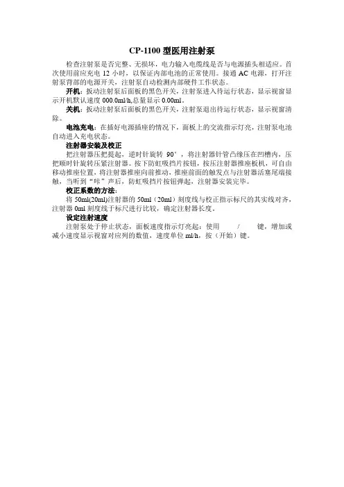
检查注射泵是否完整、无损坏,电力输入电缆线是否与电源插头相适应。
首次使用前应充电12小时,以保证内部电池的正常使用。
接通AC电源,打开注射泵背部的电源开关,注射泵自动检测内部硬件工作状态。
开机:扳动注射泵后面板的黑色开关,注射泵进入待运行状态,显示视窗显示开机默认速度000.0ml/h,总量显示0.00ml。
关机:扳动注射泵后面板的黑色开关,注射泵退出待运行状态,显示视窗清除。
电池充电:在插好电源插座的情况下,面板上的交流指示灯亮,注射泵电池自动进入充电状态。
注射器安装及校正
把注射器压把提起,逆时针旋转90°,将注射器针管凸缘压在凹槽内,压把顺时针旋转压紧注射器。
按下防虹吸挡片按钮,按压注射器推座板机,可自由移动推座位置,将注射器推座向前推动,推座前面的触发点与注射器活塞尾端接触,当听到“咔”声后,防虹吸挡片按钮弹起,注射器安装完毕。
校正系数的方法:
将50ml(20ml)注射器的50ml(20ml)刻度线与校正指示标尺的其实线对齐,注射器0ml刻度线于标尺进行比较,确定注射器长度。
设定注射速度
注射泵处于停止状态,面板速度指示灯亮起:使用/ 键,增加或减小速度显示视窗对应列的数值,速度单位ml/h,按(开始)键。
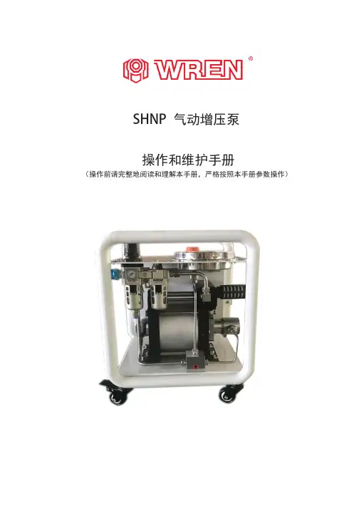
SHNP 气动增压泵操作和维护手册(操作前请完整地阅读和理解本手册,严格按照本手册参数操作)目录 1.0 介绍1.0介绍………………………………………22.0操作原理…………………………………23.0安装………………………………………34.0操作………………………………………35.0故障排除…………………………………46.0换向阀组件………………………………47.0撞针组件…………………………………68.0驱动主体及高压部分……………………7 此安装操作手册,提供了详细的信息 服务,内容为最新款SHNP 系列气 动增压泵。
SHNP 气动增压泵产品,一些组件的安 装及维护,和其他系列泵的维护相同 或相似。
本手册包含大部分信息,适用于所有 的SHNP 系列气动增压泵产品。
9.0技术参数.................................... 14 10.0 说明部分分解和补充数据 (15)条款和条件................................. 14 注意事项 (25)2.0 操作原理 危险!压缩空气或液体如果滥用可能导致严重伤害或死亡. 采取以下预防措施以减少风险. ●操作前完整地阅读和理解本手册●必须穿戴安全眼镜●加压中不要随意断开高压管路●不要在卸压时接触高压液体管路的出口●确认连接泵进出口的压力为泵的额定压力SHNP 系列气动增压泵是单头气驱液体增压泵,具有输出压力高、保压不能耗、自动吸液、自动保压、自动补压,并适用于多种介质等优点,并且应用领域广、结构简单、可靠性强、易于维护。
SHNP 系列气动增压泵广泛地应用于各种工业领域的设备配套。
如井口控制柜、胶管测试台、阀门测试台、容器测试设备、液体爆破测试台、液压工具动力包等。
SHNP 系列气动增压泵的驱动活塞直径为160mm 。
SHNP 系列气动增压泵的驱动气体入口为G1/2″,驱动气压≤8.3Bar 。
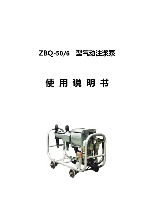
ZBQ-50/6 型气动注浆泵使用说明书(本产品按MT124-85、Q/321100ZMZ030-2007标准生产)2007年4月编写第一版2007年5月出版目录安全警示 (1)一、概述 (1)二、结构及工作原理 (1)1.产品型号及意义 (1)2. 结构 (1)3. 工作原理 (2)4. 注浆 (2)三、基本参数 (3)四、使用与维护 (4)1.开泵前的准备 (4)2.注浆中的操作 (4)3.停泵后的维护 (4)4.可能发生的故障与处理 (5)附:气动注浆泵总装示意图 (6)气动注浆泵总装示意目录 (7)安全警示1、注浆前严格检查出浆胶管接头,确保牢固可靠;2、注浆时,高压胶管不允许非人为控制甩动,确保人身、设备安全;3、整机高压部位贴有安全标识及阀门开启方向;4、工作压力不允许超过7MPa;5、配套安标件不允许随意更换厂家。
一、概述ZBQ—50/6气动注浆泵主要用于矿井,地铁、隧道、水利、建筑等注浆堵水及破碎岩层的注浆凝结工程,也可以用于矿井适应的工作面预注浆。
该泵采用气压传动,体积小,重量轻,可无级调量,能定压自动调量,使用可靠,适用于井下作业。
在易燃,易爆,强磁、辐射,多尘埃,温度变化大以及淋水的场所,均可以安全使用。
●该泵在煤矿井下使用必须配用阻燃抗静电胶管!二、结构及工作原理1.产品型号及意义Z B Q □/ □压力MPa排量L/min气动注浆泵标记示例:ZBQ-50/6表示最大排量50L/min,最大输出压力6MPa的气动注浆泵。
2.结构泵的基本结构主要由管架、气缸、活塞、端盖、联接箱、液缸、进排浆缸、换向阀和一些辅助件组成。
该泵出厂时配有φ60mm,φ100mm两种液缸和二个φ100m的套,注浆时根据需要可以更换液缸。
更换时,先松开液缸左端4个M12螺母,拆下前缸盖,拿下液缸。
当需φ60mm液缸时,只需拿下前后缸盖的套即可直接安装φ60mm 的液缸;当需φ100mm液缸时,拿下前后缸盖上φ75mm的套,换上φ100mm的套便可安装φ100mm液缸。
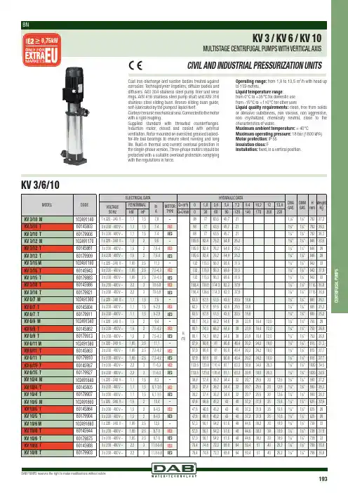
DAB PUMPS reserves the right to make modifications without notice193C E N T R I F U G A L P U M P SCast iron discharge and suction bodies treated against corrosion. Technopolymer impellers, diffuser bodies and diffusers. AISI 304 stainless steel pump liner and wear rings. AISI 416 stainless steel pump shaft and AISI 316 stainless steel sliding bush. Bronze sliding bush guide, self-lubricated by the pumped liquid itself.Carbon/ceramic m echanical s eal. C onnected t o t he m otor with a rigid coupling.Supplied standard with threaded counterflanges. Induction motor, closed and cooled with external ventilation. Rotor mounted on oversized greased sealed-for-life ball bearings to ensure silent running and long life. Built-in thermal and current overload protection in the single-phase version. Three-phase motors should be protected with a suitable overload protection complying with the regulations in force.Operating range: from 1,8 to 13,5 m3/h with head up to 139 metres.Liquid temperature range:from 0°C to +35°C for domestic usefrom -15°C to +110°C for other usesLiquid quality requirements: clean, free from solids or abrasive substances, non viscous, non aggressive, non crystallized, chemically neutral, close to the characteristics of water..Maximum ambient temperature: + 40°C Maximum operating pressure: 18 bar (1800 kPA) Motor protection: IP 55Insulation class: FInstallation: fixed, in a vertical position.KV 3/6/10。
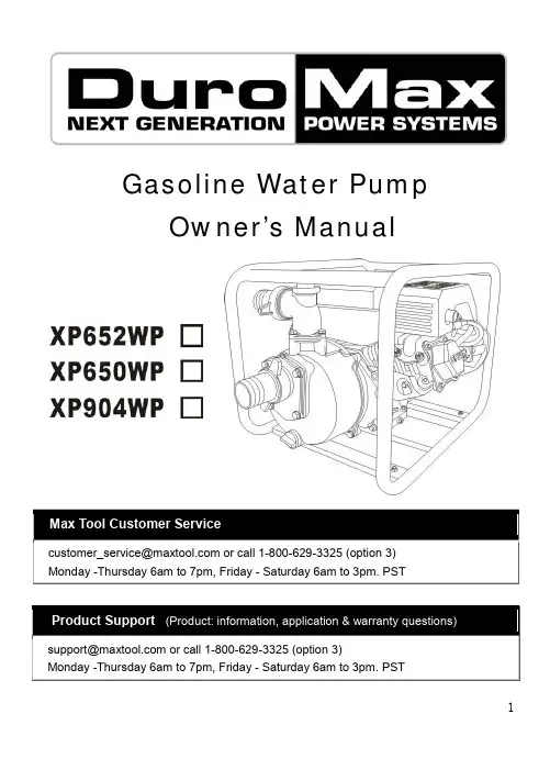
1Gasoline Water PumpOwner’s ManualThis manual provides information regarding the operation and maintenance of these products. We have made every effort to ensure the accuracy of the information in this manual. We reserve the right to change this product at any time without prior notice.Please keep this manual available to all users during the entire life of the gasoline water pump.CONTENTSⅠ. General Safeguards (1)Ⅱ. Location of Component Parts (3)Ⅲ. Operation before Starting Up (4)Ⅳ. Starting of Engine (9)Ⅴ. Use in Highland Areas (11)Ⅵ. Operation of Water Pump (12)Ⅶ. Shutting Down the Engine (13)Ⅷ. Maintenance (14)Ⅸ. Transportation and Storage (19)Ⅹ. Troubleshooting (21)Ⅺ. Specifications (23)23Ⅰ. General SafeguardsSafety PrecautionsBefore starting the engine, perform inspections according to the procedures described on pre-operation inspections to avoid accidents and damage to your machine.For safety, never attempt using this GEP (gasoline engine powered) water pump to deliver inflammable or corrosive liquids (such as gasoline and acids). Likewise, corrosive mediums, seawater, chemical solvents, alkaline liquids (such as used gasoline, liquor and honey) should be avoided.Place the water pump on a solid, level position surface to avoid tilting or turnover that may give rise to spilling of fuel.To prevent fire hazards, keep the pump well ventilated during operation and maintain a distance of at least l meter between the machine and the wall or other machines. Keep away from inflammable substances.Do not allow children and pets to enter the working area as this may increase the chance of their getting burned by hot surfaces of the operating parts.Know how to stop the water pump quickly how to operate the controls. Do not use the pump against the prescribed operating rules.WARNING :Safety PrecautionsThe gasoline fuel is highly inflammable and may explode under certain conditions.Do the fueling with the engine shut down and in a well-ventilatedenvironment. No smoking is allowed and no open fire or sparks allowed to exist in areas where fueling is carried out or the fuel is stored.Do not allow the fuel to overflow the fuel tank. Be sure to recap the tank and tighten it after refueling.When fueling, take care not to spill the gasoline about as the gasoline vapor may easily get ignited to cause a fire hazard. Be sure to remove the spilled gasoline as by wiping before starting the engine.Do not run the engine indoors or in a poorly ventilated space as the exhaust gas produced by the running engine contains toxic carbon monoxide that may cause the loss of personal consciousness or even death.45Ⅱ. Location of Component Parts6Ⅲ. Operation before Starting Up1. Connecting the water inletConnect the water inlet with a commercially available hose, connector and fastener clip. The inlet hose must be a continuous non-foldable structure with a length not more than required and should be placed near to the source of water so as to achieve the pump should be fitted to the end of the hose with the hose connector as shown in the figure below.CAUTION: Before pumping water, attach the filter to the end of the hose to filter out foreign matters in the water, the presence of which may cause clogging and damage to the wane wheel.NOTE: The hose connector and fastener clip should be securely fastened to prevent air leaks and reduction in suction power. A loosehose will reduce the pump performance and self-suction capacity.2. Connecting the water outletConnect the water outlet with a commercially available hose, hose connector and fastener clip. Large diameter hoses are the most effective while small ones will increase the flow resistance and reduce the output power of the pump.7NOTE:Be sure to the fastener clip is securely fastened to prevent the outlet hose from coming off under high water pressure.3.Checking the oil levelCAUTION:·The oil is one of the major factors affecting engine performance and life. Do not use dirty oil or vegetable oil.·Be sure to check the oil level with the engine shut down and placed on a level surface.Please use the SE15-40, 4-stroke engine oil as recommended.Please use the type of oil with a proper viscosity according to the local average temperature.Oil shortage alarm system (OSAS) (installation position)The OSAS is designed to avoid damage of the engine due to the shortage of oil in the crankcase. The system will automatically shut down the engine just before the crankcase oil level drops down to the minimum line of safety (with the engine switch staying in the ON position).If the engine is shut down and cannot be started again, check the oil level before initiating further troubleshooting procedures.Remove the oil dipstick and wipe it dry.Insert the dipstick into the oil filler but not screw it in.Replenish the crankcase with the recommended type of oil until8the oil level comes up to the upper most position of the refilled if the existing oil level is found too low.CAUTON:·Running the engine at a low oil level will cause damage to it.4. Checking the fuel levelUncap the fuel tank and check the fuel level. Pouring gasoline if the fuel level is found too low.Please use the type of gasoline recommended by the Dealer (Using the low lead content or lead-free gasoline type is good for minimizing carbon deposits inside the combustion chamber).Do not use a mixture of gasoline and oil or dirty gasoline to prevent dirt, dust or water from entering the fuel tank.CAUTION:·The gasoline fuel is highly inflammable and may explode under certain conditions.·Do the fueling with the engine shut down and in a well-ventilated environment. No smoking is allowed and no open fire or sparks allowed to exist in areas where fueling is carried out or the fuel is stored.·Do not allow the fuel to overflow the fuel tank. Be sure to recap the tank and tighten it after refueling.9·When fueling, take care not to spill the gasoline about as the gasoline vapor may easily get ignited to cause a fire hazard. Be sure to remove the spilled gasoline as by wiping before starting the engine.·Avoid frequent or extensive exposure of the skin to gasoline or breathing in the gasoline vapor. Keep the gasoline out of the reach of children.·Fuel tank capacity: 1.0 gallons (US. 3.6 liters)Screw the wing nut and remove the washer and cleaner cover.Check the filter element to see if it is too dirty and clean it if necessary.CAUTION:Do not run the engine without the air cleaner as this may quicken engine wear if dirt or dust is sucked into the engine through the carburetor.106. Checking and filling the pump with cooling waterThe pump must be filled with water before it is put to operation. CAUTION:·Do not attempt running the pump without cooling water or the pump will get overheated. Extensive running without cooling water may also damage the air tightness of the pump. If the pump is found running dry, stop the engine and pouring in water when it coolsdown.11Ⅳ. Starting engine1. Turn on the fuel tap (by setting it to the ON position).2. Close the choke.NOTE:·The choke is not required when starting the engine warm or the ambient temperature is rather high, (i.e. keep the choke open when starting the engine).3. Set the engine switch to the ON position.4. Turn the throttle control lever slowly to the left.5. Gently pull up the starter lever until a resistance is felt and then quickly pull it up.CAUTION:·Do not allow the starter lever to retract quickly into the engine. Let it go back gently to avoid damaging the starter.Ⅴ.Use in Highland AreasOperation in Highland ConditionsIn highland areas (with a high ASL elevation), the air-fuel mixture produced by a standard carburetor will be too thick and result in a reduced engine performance and soared fuel consumption. For operation in highland areas, the engine performance may be increased by using a smaller diameter carburetor nozzle and readjusting the carburetor idle speed. If the water pump is frequently used in areas with a ASL elevation of more than 1800 meters (6000 feet), ask the local dealer to replace or readjust the carburetor beforehand. Even if the engine is fitted with a carburetor nozzle of an appropriate size, the engine power will still go down by about 3.5% each time when the ASL elevation goes up by 305 meters (1000 feet). If no replacement or readjustment is ever made of the carburetor, the highland effect of the engine output power will be even more obvious.CAUTION:1213·Using the water pump in areas where the ASL elevation is lower than suitable for the carburetor nozzle will lead to a decreased engine performance and overheating of the engine and even cause serious damage to the engine due to an extremely thin air-fuel mixture.Ⅵ. Operation of the Water Pump1. Gradually open the choke after the engine warms up.2. Set the throttle to the predetermined RPM.Ⅶ. Shutting Down the Engine1. Set the throttle control lever to the right end.2. Set the engine switch to the OFF position.3. Turn off the fuel tap (by setting to the OFF position).NOTE:·To shut down the engine in an emergency, simply set the engine switch to the OFF position.Ⅷ. MaintenancePeriodic inspections and fine-tuning are simply indispensable to keep the water pump working with high performance and regular maintenance may also lengthen the pump life. Supplied in the table on the next page are intervals at which the schedules maintenance jobs are to be done.WARNING:·Before any maintenance attempt, be sure to shut down the engine. If the maintenance job has to be done with the engine at work, it should take place in a well-ventilated space as the exhaust gas contains toxic carbon monoxide that causes the loss of personal consciousness or even death.14CAUTION:·In cases when the pump is used to suck up seawater, be sure to flush it with fresh water immediately after use to minimize corrosion and remove deposits.·Always use the original parts and relevant tools supplied with the machine to carry out maintenance. Failure to do this may cause damage to the pump.NOTE:⑴Inspection and maintenance should take place more frequently if the pump is used in a dirty environment.⑵Leave the following inspection and maintenance jobs to the authorized dealers unless you, the user, have the relevant tools and necessary DIY skills. In the latter case, refer to service manual.16general power machinery Co., Ltd.1. Replacing the engine oilOil drains easily and quickly while the engine is warm.1. Remove the oil dipstick and drain bolt to let out the oil.2. Screw the drain bolt back in place and tighten it.3. Pour in clean oil until the desired level is reached.Oil sump capacity: 0.6 litersClean the hands with soap if stained with the engine oil.NOTE: Be sure to keep the environment clean when disposing used engine oil. We suggest you collect the waste oil in a container to be sent to a waste disposal site or a recycling service center of spill it in the garbage or on the ground.2. Maintaining the air cleanerA dirty air cleaner will let less air into the carburetor. To prevent carburetor malfunctions, be sure to maintain the air cleaner periodically. More frequent maintenance of the air cleaner will be necessary if the pump is working in an extremely dirty environment. DO not clean the air cleaner with a low ignition point solvent because it may get enflamed or even explode under certain17circumstances.CAUTION: Do not use the water pump without an air cleaner. Thedirt or dust if sucked into the engine may quicken engine wear.1) Unscrew the wing nut and remove the air cleaner cover and filter element.2) Clean the filter element with a detergent solution inflammable or with a high ignition point and let it dry thoroughly after cleaning.3) Immerse the filter element into clean oil and then squeeze out the excessive amount of oil.4) Put the filter element as well as the air cleaner back in place.3. Maintaining the spark plugThe recommended type of spark plug is NHSP LD P6RTCU.To ensure normal operation of the engine, the spark plug should have a correct gap and should remain free of carbon deposits.1) Remove the plug cap.The muffler may be very hot if the engine is still running. Take care not to touch the muffler.2) Check the spark plug visually. Discard the spark plug if it is18obviously worn out or the insulation ring on it is broken or cracked. Clean the spark plug with a brush when put it back in place.3) Check the plug gap with a feeler gauge.Vary the gap by moving the side electrode.Normal plug gap: 0.70~0.80mm4) Check the plug O-ring for normal condition. Screw it in with theplug wrench to protect the plug thread.NOTE:·In the case of screwing in a new spark plug, tighten it by an additional 1/2 screw turn after the plug reaches and pushes on the O-ring, while in the case of a used spark plug, an additional 1/2~1/4 screw turn is necessary.CAUTION:·Make sure the spark plug is properly tightened. Impropertightening may cause the engine to be overheated or damaged. Never use spark plugs with an incorrect thermal value range.Ⅸ. Transportation and Storage CAUTION:·To avoid causing a fire hazard, let the engine cool down before transportation or indoor storage of the pump.·Before transporting the pump, set the fuel tap to the OFF position and place the pump body in a level position to prevent the fuel from spilling out. The spilled gasoline or the gasoline vapor may get ignited.Note and do the following before storing pump for an extended period of time:1) Make sure the storage area is free of moisture or dust.2) Ch\lean the inside of the pump.The pump may get clogged if it is used to suck up water containing such matters as earth, sand or heavy fragments.Before storing, clean the pump by sucking up clean water or otherwise the wane wheel may be damaged when the pump is put to use again. After cleaning, unscrew the water drain plug to drain off the water from inside the pump casing as much as possible. Then screw the drain plug back into place.3) Drain off the fuel.a. Turn off the fuel tap (OFF position), unscrew the drain screw from the carburetor float chamber to drain off the fuel from inside the carburetor and collect the gasoline in a suitable container.b. Turn on the fuel tap (ON position) and collect the gasoline in a suitable container.c. Screw the carburetor fuel drain screw back into place.19204) Replace the engine oil.5) Screw off the spark plug, pour a spoonful of clean oil into the cylinder, turn the engine alternatively for several times to allow uniform distribution of oil, and then screw in the spark plug again.6) Pull up the starter lever until a resistance is felt. Stop pull for a while and pull it up again until the triangle mark on the starter wheel gets into collimation with the screw hole in the starter (as shown the sketch below). In this position, both the inlet valve and outlet valve is closed to prevent corrosion inside the engine.7) Cover up the pump to keep out dust.Ⅹ. TroubleshootingEngine unable to get started:1) Is there enough fuel?2) Is the fuel tap turned on?213) Has the fuel reached the carburetor? Make the check by unscrewing the oil drain screw from under the carburetor with thefuel tap turned on.WARNING:·Should there be a spill of fuel, be sure to clean it before checking the spark plug and start the engine or otherwise the spilled fuel or fuel vapor may get ignited4) Is the engine switch set to the ON position? 5) Is there enough oil in the crankcase? 6) Is the spark plug generating sparks?a. Uncap the spark plug, clear off the dirt from around the plug and remove the spark plug.b. Fit the spark plug into the plug cap.c. Turn on the engine with the side electrode and pull up the starter lever to see if there is sparks generated.d. Ground the engine with the side electrode and pull up the starter lever to see if there is sparks generated.e. Replace the spark plug if no spark is found.Start the engine as directed in the operation manual if sparks are generated.7) If the engine still refuses to get started, send the pump to any of the authorized dealers.22The pump unable to such up water: 1) Is it filled with enough amount of water?2) Is the filter clogged?3) Is the hose fastener clip tightened? 4) Is the hose damaged?5) Is the suction head too high?6) If the pump still fails to work, send it to any of the authorized dealers.Ⅺ. Specifications2324PARTS LIST AND ASSEMBLY (XP652WP/XP650WP)2526272829XP652WP3031XP650WP3233PARTS LIST AND ASSEMBLY(XP904WP)353637。

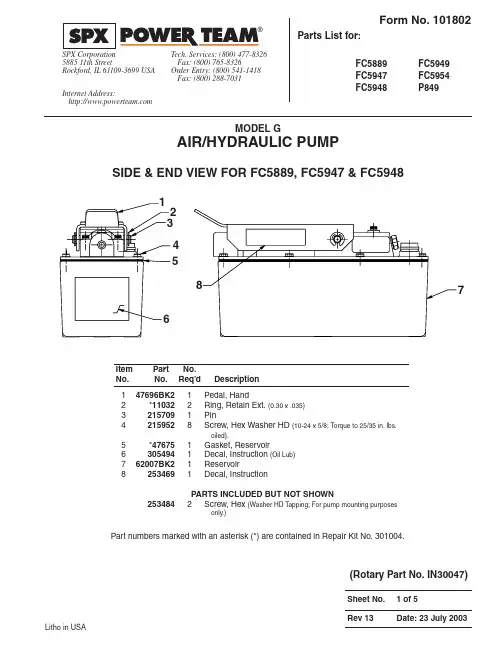
MODEL GAIR/HYDRAULIC PUMPSIDE & END VIEW FOR FC5889, FC5947 & FC5948Litho in USA12348567Part numbers marked with an asterisk (*) are contained in Repair Kit No. 301004.147696BK21Pedal, Hand2*110322Ring, Retain Ext. (0.30 x .035)32157091Pin42159528Screw, Hex Washer HD (10-24 x 5/8; Torque to 25/35 in. lbs.oiled).5*476751Gasket, Reservoir63054941Decal, Instruction (Oil Lub)762007BK21Reservoir82534691Decal, InstructionPARTS INCLUDED BUT NOT SHOWN 2534842Screw, Hex (Washer HD Tapping; For pump mounting purposesonly.)(Rotary Part No. IN30047)1371991Body, Air Intake Valve2111514Screw, Socket HD (10-24 x 1-1/4; Torque to 50/60 in. lbs.) 3421813BK21Plate, Cover4590511Body, Release Valve5114352Screw, Socket HD (10-24 x 1-3/4; torque to 50/60 in. lbs.) 6110892Washer, Flat (.51 x .22)7*299921T ube, Foam92516891Cap, Filler Breather10*102732O-ring (.81 x .62 Nitrile)11647671Body, Pump12174284Screw, Socket HD (1/4-20 x 3-1/2; Torque to 85/95 in. lbs. oiled;Note: Cross torque in increments of 30 in. lbs.)Part numbers marked with an asterisk (*) are contained in Repair Kit No. 301004.147696BK21Pedal, Hand2†110322Ring, Retain Ext. (0.30 x .035)32157091Pin42159526Screw, Hex Washer HD (10-24 x 5/8; Torque to 35/42 in. lbs.oiled).5†338531Gasket, Reservoir6†3054941Decal, Instruction (Oil Lub)741300BK21Reservoir82534691Decal, Instruction 92516721Decal, WarningPARTS INCLUDED BUT NOT SHOWN 2534842Screw, Hex (Washer HD Tapping; For pump mounting purposesonly.)Parts List Form No. 101802SIDE & END VIEW FOR FC5949 & FC5954123456789Part numbers marked with a dagger (†) are contained in Repair Kit No. 301021.1371991Body, Air Intake Valve2111514Screw, Socket HD (10-24 x 1-1/4; Torque to 50/60 in. lbs.)3421870BK21Plate, Cover4590511Body, Release Valve5114352Screw, Socket HD (10-24 x 1-3/4; torque to 50/60 in. lbs.)6110892Washer, Flat (.51 x .22)7†299921T ube, Foam92516891Cap, Filler Breather 10†102732O-ring (.81 x .62 Nitrile)11647671Body, Pump12174284Screw, Socket HD (1/4-20 x 3-1/2; Torque to 85/95 in. lbs. oiled;Note: Cross torque in increments of 30 in. lbs.)Part numbers marked with a dagger (†) are contained in Repair Kit No. 301021.124356791011121413221Pedal, Foot2•110322Ring, Retain Ext. (0.30 x .035)3283861Pin425295212Screw, Round HD (1/4-20 x 3/4)5•462711Gasket, Reservoir6•3054941Decal, Instruction (Oil Lub)764153BK21Reservoir82517622Decal, WarningParts List Form No. 101802SIDE & END VIEW FOR P84912345678Part numbers marked with a bullet (•) are contained in Repair Kit No. 301012.1371991Body, Air Intake Valve2111514Screw, Socket HD (10-24 x 1-1/4; Torque to 50/60 in. lbs.)3647671Body, Pump4174284Screw, Socket HD (1/4-20 x 3-1/2; Torque to 85/95 in. lbs. oiled;Note: Cross torque in increments of 30 in. lbs.)5•102732O-ring (.81 x .62 Nitrile)62516891Cap, Filler Breather 75010001Body, Release Valve8114352Screw, Socket HD (10-24 x 1-3/4; torque to 50/60 in. lbs.)9110892Washer, Flat (.51 x .22)1059302BK21Plate, Cover 11•299921T ube, FoamPart numbers marked with a bullet (•) are contained in Repair Kit No. 301012.1234567891011Parts List Form No. 1018021•†*281821Poppet, Air Valve 2•†*2517171O-ring (1.00 x .62 Nitrile)3283871Muffler 4•†*282391Gasket5523901Body, Piston6•†*142652Ring, Piston (2.77 x 2.54)7•†*2518352O-ring (2.50 x 2.31 Nitrile)8•†*102761O-ring (1.00 x .75 Nitrile)9•†*102721O-ring (.75 x .50 Nitrile)10343781Body, Check Valve11•†*2145961Disc, Filter (Not part of P849)12•†*122012Ring, Retain Int. (0.18 x .010)13*•†2110532O-ring (.37 x .25 Nitrile)14171471Fitting, Plug (7/16; Not part of P849)109701Fitting, Plug (1/4 NPTF; For P849)15•†*118411O-ring (1.62 x 1.37 Nitrile)16•†*3510211Gasket, Cover Plate17•†*104421Washer, Copper (.37 x .25)18100021Screw, Socket HD (1/4-20 x 3/8;Torque to 90/110 in. lbs.)19•†*104451Spring (.16 OD x .72 x .01 WS)20•†*104232Ball (9/32" Dia. Steel)2121278-321Valve, Relief(Set at3,100/3,300 PSI;For FC5889)21278-201Valve, Relief(Reset at1,700/1,900 PSI;For FC5947)21278-201Valve, Relief(Reset at1,800/2,000 PSI;For P849)21278-251Valve, Relief(Reset at2,200/2,400 PSI;For FC5948)21278-351Valve, Relief(Set at3,500/3,800 PSI;For FC5954)21278-351Valve, Relief(Reset at3,500/3,700 PSI;For FC5949)224216421Housing, Seal & Piston (Torque to90/100 ft. lbs. oiled)23•†*102611Washer, Copper (.75 x .60)244215391Adapter, Filter (Torque to 40/50 ft.lbs. oiled; For FC5889, FC5947 &FC5948)480101Adapter, Filter (Torque to 40/50 ft.lbs. oiled; For FC5949, FC5954 &P849)252145781Filter262145861Ring, Retain Int. (0.63 x .015)27•†*102631Washer, Special (1.00 x .77)28•†*3516621Retainer (Note: See “INSTRUCTIONSFOR RET AINER REPLACEMENT” on back sheet 5 of 5.)29•†*124881Washer, Backup (.63 x .44)30•†*2530951U-cup (.69 x .44 x .25 H)31•†*174292Washer, Backup (2.94 x 2.75)32•†*139381Spring (1.45 OD x 4.4 x .12 WS)33284001Piston (7/16”)34•†2026131Bumper352110821Guide, Spring36374341Cylinder, Air (Locate groove onupper half (top) of pump with chamfered tube end towards rear head as shown.)37•†*126921Spring (.18 OD x 1.70 x .02 WS)38•†*2110521O-ring (.90 x .70 Nitrile)393054751Stem, Exhaust Valve 40•†*102413Washer,Lock (.33 x .20)412110543Screw, Socket HD (10-24 x 1/2;Torque to 50/55 in. lbs.)42338221Casting, Piston End Plate 43•†*281831Poppet, Piston44•†*2056791Spring (.49 OD x .92 x .04 WS)45•†*2056741Screw, Flat HD (8-32 x 3/8; Torqueto 12/18 in. lbs.)46514801Head, Rear47•†*2533481Spring (.36 OD x 1.50 x .05 WS)482534201Screw, Button Head (8-32 x 1/4)49281981Guide, Seal 50•†*2162961Filter51•†*102671O-ring (.43 x .31 Nitrile)52338411Button, ActuatorPart numbers marked with an asterisk (*) are contained in Repair Kit No. 301004.Part numbers marked with a dagger (†) are contained in Repair Kit No. 301021.Part numbers marked with a bullet (•) are contained in Repair Kit No. 301012.(ApplyLoctite 592[PT#905516]or equiv.and torque to 150/170in. lbs.)Parts List Form No. 101802DETAIL A1•†*2065041T ube, Foam2282271Button, Release Valve3•†*102661O-ring (.37 x .25 Nitrile)4•†*2512971Spring (.36 OD x .51 x .05 WS)5343771Retainer, Poppet6•†*152791O-ring (.50 x .37 Nitrile)7139371Pin, Dowel (.06 x .63)8290371Poppet, Release Valve9•†*144431Ball (3/32" Dia. Steel)102097361Retainer, Ball11•†*139591Spring (.12 OD x .50 x .02 WS)12•†*156201Seal, Oil Shaft (.50 x .25 NIT)Part numbers marked with an asterisk (*) are contained in Repair Kit No. 301004.Part numbers marked with a dagger (†) are contained in Repair Kit No. 301021.Part numbers marked with a bullet (•) are contained in Repair Kit No. 301012.Retainer。
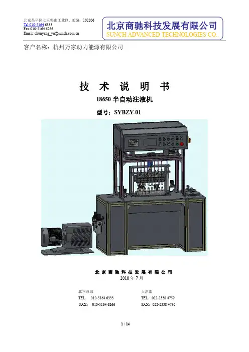
客户名称:杭州万家动力能源有限公司技术说明书18650半自动注液机型号:SYBZY-01北京商驰科技发展有限公司2010年7月北京总部天津部TEL:************TEL:************FAX:************FAX:************1 设备简介1.1 外观及基本原理此型号注液机的基本原理及外观如图1.1和图1.2所示。
图1.1 注液系统机构原理图1.2 注液机外观图本型号注液机主要用于圆柱形铝壳电池的注液,适用于电池型号18650。
在小批量和中试生产18650圆柱锂离子电池的专用生产工艺过程中,本机用于给电芯定量注电解液。
高可靠性的实现18650电芯的高精度注液要求;本机提供了详尽的参数设置功能,方便用户进行注液工艺的研究。
1.3 使用条件洁净车间环境:温度:23±5°C,湿度:≤50%;电源:单相AC220V,50Hz,2.5KV A;压缩空气:0.5~0.6MPa;清洁氮气:0.4~0.5MPa;1.4 性能指标注液机最大功率0.5Kw,由8个注液工位组成。
表1.1 注液机性能指标1.5产品优点1)注液时差压控制(高、低真空切换),可有效抑制电解液的雾化,提高注液效率;2)真空回路追加冷凝装置及活性炭过滤装置,减少回路中的气态电解液,更好的保护真空回路中的元器件;3)注液回路增加DMC清洗功能,防止残留的电解液结晶体堵塞注液回路;4)注液机分8个注液工位,每个工位可以人工独立启闭作业;5)可进行多参数设置,使注液工艺更加灵活、精细化;1.6 使用说明详见SYBZY-01电池注液系统使用维护说明书。
2 机构组成及原理2.1 注液机机构本型号注液机由8个部件组装而成,其中包括机体机架、注液杯、电池载体、注液架、冷凝装置、过滤装置、真空泵和废液搜集装置,下文分别介绍。
1、机体机架该支架包括安装架、电气配电柜及操作面板。
材料95%以上都采用不锈钢材质。
Environmental conditions can affect product performance and longevity; consult the product instructions on or contact a Technical Sales Representative for more information.Based on product information at time of publication.Standard Pad Spread:P11104DC: 51" x 12” [1295 x 305 mm]P11004DC: 49” x 10” [1245 x 254 mm]P1HV1104DCO: 50" x 11" [1270 x 280 mm]Number / Size of Pads:P11104DC: 4 / 11" [28 cm] dia. lipped P11004DC: 4 / 10" [25 cm] dia. concave P1HV1104DCO: 4 / 10" [25 cm] dia. lippedLoad Capacity:(On smooth, nonporous surfaces.Please contact us for recommendations on other surfaces.)P11104DC: 700 lbs [320 kg]P11004DC: 600 lbs [270 kg](Capacity is reduced on curved surfaces.Please contact us for capacity on curved surfaces.)P1HV1104DCO: 600 lbs [270 kg] Average Unit Weight: 90 lbs [41 kg]Standard Operating Power:12 volts DC, 10 amps (for each Pad Channel)Load Movement:Manual rotation, 180° edgewise, with locking in three positions.Manual tilt, 90° between upright and flat, with automatic latching in upright position. (Units can be tilted ONLY when the lift bar is locked in the center position, as shown on drawings.)Standard Features:Adjustable-position lift spool On-board battery and charger Battery energy gauge Low vacuum warning light Vacuum gauge Vacuum line filterVacuum reserve tankAlternative Power Systems:Air (venturi) power system (P11104AIRS, P11004AIRS or P1HV1104AIRS)AC power system (P11104AC, P11004ACO or P1HV1104ACO)(Specifications may not be as listed above. Please contact us for more information.)Available Options:Dual vacuum system (P11104DC2, P11004DC2 or P1HV1104DC2O)ABS shipping case (53005) (see page 2 for more information)Counterbalance Lifter (CB2DCS)Design Standards:(See for more information.)ASME B30.20 - 2006(BTH-1 Design Category "B", Service Class "0") AS 4991 - 2004vacuum lifters provide 180° rotation and 90° tilt, for expandability and a full range ofload motion at the installation site or on the shop floor.COMPONENTSPAD CHANNELSEach channel features an independent, on-board vacuum generating system, including vacuum pump, vacuum controls and standard features as listed on page 1.PC1104DC: (for flat materials) 4 / 11” [28 cm] dia. lipped pads (94110, 94111, 94112)PC1004DCO: (for curved materials) 4 / 10” [25 cm] dia. concave pads (special order)PCHV1104DCS: (for rough materials) 4 / 10” [25 cm] dia. lipped pads (special order)LIFT FRAMESPCFT1A1: For one Pad Channel (94154)PCFT2SA45: For two Pad Channels, approx. 4½’ [1.38 m] pad spread (94165)PCFT2SA7: For two Pad Channels, approx. 7’ [2.14 m] pad spread (94170)INTERCHANGEABLE ARMS(Pad spread can be changed if optional arms are purchased)FA245: Optional arms convert PCFT2SA7 Lift Frame to PCFT2SA45 Lift Frame (57222AM)FA27: Optional arms convert PCFT2SA45 Lift Frame to PCFT2SA7 Lift Frame (57223AM)SHIPPING CASE FOR P1 VACUUM LIFTERS(vacuum lifter and case sold separately)Designed specifically for shipping and storing Powr-Grip ® P11104, P11004 and P1HV1104 Vacuum Lifters.Durable thermo-formed ABS construction.Three straps on inside of case hold vacuum lifter firmly in place. Eight plastic buckles attached to nylon straps hold case in closed position. Handles molded into the case structure enable convenient handling. Ribbed exterior of case enables easy stacking of multiple lifters. Case design incorporates grooves on the bottom to facilitate forklift handling.Channel Lifters are comprised of one or more Pad Channels, for gripping loads, plus interchangeable Lift Frames, for rotating and tilting materials. These vacuum lifters may be ordered as complete units or as individual components to expand existing Channel Lifter systems. Lift Frames are available in single-channel or double-channel styles. Pad Channels can be switched from one frame to another in minutes.。
第1篇一、适用范围本规程适用于所有使用气动泵的设备和系统,包括但不限于工业生产、实验室研究、环保设施等场合。
二、操作前的准备1. 检查气动泵外观,确保无损坏、腐蚀等现象。
2. 检查连接管道,确保无泄漏、破损等现象。
3. 确认电源电压符合气动泵要求。
4. 确认气动泵进出口管道畅通无阻。
5. 检查气源压力,确保符合气动泵工作要求。
三、操作步骤1. 开启气源,调整气源压力至气动泵额定工作压力。
2. 打开气动泵进出口阀门,确保气动泵处于正常工作状态。
3. 根据实际需求调整气动泵的转速,以达到所需的流量和压力。
4. 在操作过程中,密切观察气动泵的工作状态,如发现异常情况(如噪音增大、振动加剧等),应立即停止操作,检查原因并处理。
5. 定期检查气动泵运行情况,如发现磨损、损坏等,应及时更换或维修。
四、操作注意事项1. 操作人员应熟悉气动泵的操作规程和设备性能,未经培训不得操作。
2. 操作过程中,严禁将手、脚等部位伸入气动泵进出口管道内。
3. 严禁在气动泵工作时对其进行拆卸、维修等操作。
4. 严禁在气动泵运行时调整气源压力,以免损坏气动泵。
5. 严禁将气动泵用于输送易燃、易爆、有毒等危险物质。
6. 严禁将气动泵用于超出其额定工作压力、流量等参数的工作场合。
7. 严禁将气动泵用于非气动泵设计用途的场合。
五、维护保养1. 定期清理气动泵进出口管道,防止堵塞。
2. 定期检查气动泵密封件,如发现磨损、损坏等,应及时更换。
3. 定期检查气动泵轴承,如发现磨损、松动等,应及时更换或紧固。
4. 定期检查气动泵电气元件,如发现损坏、老化等,应及时更换。
5. 定期检查气动泵整体结构,如发现锈蚀、变形等,应及时处理。
六、安全措施1. 操作人员应穿戴适当的防护用品,如安全帽、防护眼镜、防护手套等。
2. 操作区域应设置警示标志,提醒人员注意安全。
3. 操作过程中,严禁酒后操作。
4. 严禁在气动泵运行时进行维修、拆卸等操作。
5. 严禁将气动泵用于非气动泵设计用途的场合。
longerpump lsp01-2a说明书
产品说明:
1、LSP01-2A注射泵是一款单通道灌注型注射泵,能够装卡不同规格的注射器(进样器),适合高精度、小流量的液体传输
2、人机界面友好:大屏幕液晶显示,数码旋钮于薄膜按键配合使用,操作简便,快捷
3、工作模式:单推工作模式
4、采用485通讯总线可与上位机相连,通过后台软件对其进行控制。
参数:
1、外控接口:具备输入/输出控制功能
2、液量校准功能:通过校准程序可得到更的流量
3、注射器保护功能:通过调整限位块位置,可以防止注射器受损
4、注射器内径输入功能:可从列表中选择注射器或者直接输入注射器内经
5、堵车保护功能:当工作过程中注射泵的推进机构被堵死,注射泵会停止推进机构的工作发出鸣笛警报
6、掉电记忆功能:EEPROM保存设置参数,重新上电后,无需重新设置;流量模式下运行时断电,恢复上电后可根据设置参数继续运行或停止
LSP01-2A与LSP01-1A比较:
1、LSP01-2A增加5倍减速脉动更小
2、LSP01-2A更适用于细胞分析
3、LSP01-2A更适合传输小流量的液体。
五十气动隔膜泵的说明书一、产品概述五十气动隔膜泵是一种新型输送机械,采用压缩空气为动力源,对于各种腐蚀性液体,带颗粒的液体,高粘度、易挥发、易燃、剧毒的液体,均能予以抽光吸尽。
它具有自吸能力强、耐腐蚀、防爆等优点,被广泛应用于化工、制药、食品、环保等行业。
二、工作原理五十气动隔膜泵的工作原理是通过压缩空气驱动膜片往复运动,从而改变泵腔内的容积,实现液体的吸入和排出。
当压缩空气进入泵的一侧气室时,推动膜片向另一侧移动,此时该侧气室容积增大,形成负压,将液体吸入;同时,另一侧气室的膜片被压缩,容积减小,将液体排出。
如此循环往复,实现连续的液体输送。
三、产品特点1、无密封设计,不会产生泄漏,可输送易燃易爆、有毒有害等危险介质。
2、自吸能力强,无需灌引水,启动前无需注液,能抽送流动的液体,也能输送一些不易流动的介质。
3、流量可调节,通过调节气源压力或控制气阀开度,可以方便地改变泵的流量。
4、可通过改变气源进出口方向,实现正反向输送。
5、结构简单,易于维护,仅由几个主要部件组成,维修成本低。
6、能适应恶劣的工作环境,如高温、低温、潮湿、腐蚀等。
四、技术参数1、最大流量:_____升/分钟2、最大扬程:_____米3、最大供气压力:_____MPa4、进出口管径:_____mm5、重量:_____kg五、安装与调试1、安装前应检查泵体、膜片、进出口管道等部件是否完好,有无损坏或变形。
2、安装时应确保泵的进出口与管道连接牢固,密封良好,避免泄漏。
3、安装位置应选择平稳、干燥、通风良好的地方,便于操作和维护。
4、调试前应先将气源接通,检查气源压力是否符合要求。
5、启动泵,观察泵的运行情况,检查有无异常声音、振动和泄漏。
6、调节气源压力和控制气阀,使泵的流量和压力达到工作要求。
六、使用注意事项1、气源应干净、干燥,避免含有杂质和水分,以免影响泵的正常运行。
2、定期检查膜片的磨损情况,如有损坏应及时更换。
3、严禁在泵体无液体的情况下长时间空运转,以免损坏膜片和其他部件。
Model #Serial #Drawing #Order #Mfg. DateT able of C onTenTs page1.0 Introduction (3)2.0 Meaning of Safety Words (3)3.0 Product Specification (3)4.0 Unpacking (3)5.0 Tools (3)6.0 Installation (3)6.1 Compressed Air Supply (4)6.2 Liquid Section (4)7.0 Pump Start-Up (5)8.0 Process Media (5)9.0 Pump Functionality (6)10.0 Suggested Maintenance (6)11.0 Trouble Shooting-Pneumatic Section (7)12.0 Trouble Shooting-High Pressure Liquid Section (7)13.0 Service (8)Section 1.0IntroductionThe Parker Autoclave Engineers pump discussed in this manual is operated using compressed air up to 150 psi (10 bar). Parker Autoclave Engineers ACL Series pumps are used for pumping oil, water and oil/water mixtures. Special seals are also available for chemical service. Please contact Parker Autoclave Engineers to discuss availability of special seals. The pump operates using a pressure ratio of the air piston surface area to the liquid plunger surface area.(Output liquid pressure = actual pump pressure ratio x input air pressure). Refer to the product literature for each pump model's actual air pressure ratio.Section 2.0Meaning of Safety WordsA safety related message is identified by a safety alert symbol and a signal word to indicate the level of riskinvolved with a particular hazard. The definitions of the three signal words are as follows:indicates a potentially hazardoussituation which, if not avoided, could result in death or serious injury.indicates a potentially hazardoussituation which, if not avoided, may resultin minor or moderate injury.Special notes intended to bring attention to procedures that must be followed to ensure proper installation and performance will be placed in a box labeled NOTICE.Section 3.0Product SpecificationSee assembly drawing for product specifications:- Pump Geometry- Pump Materials of Construction- Maximum Allowable Working Pressure - Maximum Working Temperature - Pressure Ratio - Displacement- Repair Kit Part Numbers - Torque Information - WeightsSection 4.0UnpackingThe pump has been assembled and pressure tested at Parker Autoclave Engineers and is ready to be put into service. The shipping carton should be opened and the contents carefully examined upon receipt from the carrier. Make sure there is no obvious damage to the contents. DO NOT use the equipment if any damage is evident. If damage has occurred, file a claim with the shipper before contacting Parker Autoclave Engineers Service Department.Examine all material within the container and check against the packing list to be sure all items are accounted for and are not damaged. Verify that the equipment model number supplied agrees with what was ordered.Section 5.0ToolsAt minimum, the tools required for installation of the pump in-clude a torque wrench, an open end wrench adapter (crows foot adapter) and an open end adjustable wrench.Refer to the Tools, Maintenance and Installation Manual provided with the Data Book for information on torque wrenches and torque values for Parker Autoclave Engineers tubing and fittings.Section 6.0InstallationFor best performance and life, the pump should be installed in the vertical position. This will prevent side loading on the air piston seals. The pump will, however, function in any position.The pump will attach to the mounting location using (4) 5/16" bolts. There are 4 holes provided on each pump for mounting.Section 6.1Compressed Air SupplyThe main air drive connection port on the pump is a female 1/4" FNPT and is located in the spool valve housing.An air line filter with a minimum 5 microns filtration rating must be used on the supply line. If the air supply is not dry, a mist separator must be used to remove moisture in the air line.Parker Autoclave Engineers can supply a complete air control package that includes a filter, air pressure regulator, air pres -sure gage and shutoff valve. Mist separators are also available. Contact the factory for more details on these options.The pump is designed to function from 15 psi to 150 psi (1 to 10 bar) air input pressure.Unless otherwise noted, all air line accessories for the pump air drive should have, at minimum, a 1/4" FNPT connection. The tubing/piping used to connect the components should have the maximum ID the pressure rating will allow. Reduc-ing the size before the air inlet will reduce air pressure flow and reduce flow rate of the pump.NOTICEThe use of an air line lubricator is not required and is not recommended. The oil in the air lubricator will cause the factory installed grease to be purged from the pump. Once an air lubricator is used the pump can never again be oper-ated without an air lubricator.NOTICESection 6.2Liquid SectionAll ACL series pumps have a high pressure liquid outlet port located on the side of the pump head. The suction inlet port on all ACL series pumps is positioned either at the bottom or side of the head depending on the model purchased. See order code details in the product literature for catalog number suffix.Inlet: A liquid filter with at least a 100 mesh sizemust be installed before the suction port inlet to prevent damage to the check valves and high pressure seals due to debris.The tubing or piping should be made from a corrosion resistant material and sized with a maximum ID to fit the 3/8" pipe con -nections.Outlet: The outlet tubing ID must, at minimum, match the same size of the pump check valve gland port. Refer to product litera-ture for outlet connections details for each pump. Reducing out-let tubing or connection will reduce output liquid flow capacity.For best performance, a liquid supply reservoir should be located higher than the inlet gland on the pump to create a small pressure head. Be sure to make an air tight seal between the reservoir and the pump inlet connection. The connections between the reservoir and pump inlet should not be reduced from the 3/8" FNPT connection size.NOTICERestricting flow at the liquid inlet will cause problems withcheck valve performance and reduce output flow.NOTICEIncrease the air pressure using the air pressure regulator until you achieve your desired output liquid pressure. At this point the pump will stall. You can calculate the output pressure by multiplying the input air supply by the actual pressure ratio of the pump. The pump will automatically restart if there is a drop in downstream high pressure.Section 8.0Process MediaParker Autoclave Engineers pumps discussed in this manual are used for pumping oil, water and oil/water mixtures. Special seals are also available for chemical service. Please contact Parker Autoclave Engineers to discuss availability of special seals.Section 7.0Pump Start-UpFig. 7.0 Air Line SchematicAs shown above, a filtered main air supply line is required. The filtered air supply will go to a pressure regulator which can be set to achieve the desired output liquid pressure according to the pressure ratio of the pump.The pumps unique design allows for self priming. To prime, regulate the air pressure to between 5-15 psi or use an air flow regulator to reduce to a slow stroke frequency. With the high pressure side connected to a vented system, allow the pump to cycle until a consistent flow of liquid is achieved. Let the pump flow freely to purge any air in the liquid system. Loosening the outlet gland or pipe can also assist in priming the pump.Pumps are not designed to run for long periods of time without liquid process media. Short, dry pumping cycles should not be a cause for concern. However, pumps are built using lubricant in the seal areas and pumping without fluid will wear away lubricant and compromise the seal.The operating temperatures of the pump are between 0°F to 140°F (18°F to 60°F).Section 9.0Pump FunctionalityWhen the pump is installed, regulated air is connected to the spool housing at the 1/4" FNPT pump inlet.1) Regulated inlet air pressure enters spool housing and moves spool to the left directing air into large pressure tube to the bottom end cap pushing the air piston and liquid plunger upward.2) The upward movement causes a suction of liquid into the high pressure pump head while inlet check valve is open and outlet check valve is closed.3) The air piston continues to move up until it hits the p ilot valve assembly in the top end cap.4) The top pilot valve opens allowing max system air pressure to shift the spool valve so that it now directs air drive pressure through the top end cap and pushes the air piston and liquid plunger downward.5) The plunger action moving down compresses the fluid on the high pressure pump head while the inlet check valve is closed and outlet check valve is open.6) While the air drive pressure is acting on top of the piston, the bottom area of the piston is vented through the exhaust muffler.7) Piston continues to move down until it hits the pilot valve assembly in the bottom end cap.8) The bottom pilot opens which vents maximum system air pressure from the large diameter side of the spool.9) This causes spool to move to the left, while air is vented from the top end of the air cylinder through the exhaust muffler. 10) The entire process starts again at step one until themaximum outlet hydraulic pressure in reached based on the pressure ratio of the pump.s eCTion 10.0Suggested MaintenanceA. Before each pump use, a quick inspection should be per-formed to insure there are no loose bolts, nuts, set screwsor check valve glands. Tighten any lose bolts and fittingsaccording to the torque values listed on the pump assembly drawing. A visual inspection should also be made beforeeach use and at startup to make sure there is no evidence of fluid leaks from isolation chamber drain ports, check valves connections and muffler. If liquid mists out of the muffler for more than 5 strokes, it is time to replace your hydraulic high pressure seals. Refer to the troubleshooting guide for solu-tions to these fluid leaks.B. The maintenance schedule of the pump depends on thefrequency of use, cleanliness of media, type of media, cycle rates, output pressures, cleanliness of air or any other condi-tions that may be damaging to seal integrity. Once a clearpattern develops of how long a pump is in service beforepump performance declines, it is recommended to perform maintenance in advance of this time frame. At minimum,perform maintenance on the pump once a year as described below.Maintenance would include:• Re-lubrication or replacement of spool valve o-ring• Re-lubrication or replacement of air drive seals• Re-lubrication or replacement of pilot valve o-rings andgaskets• Replace check valve components• Replace high pressure hydraulic sealsC. Maintenance instructions are supplied with appropriate rebuildkits. Kit part numbers are listed on the assembly drawing.Section 11.0Trouble Shooting - Pneumatic SectionProblem: Pump will not operate with low air pressure.Cause: Excessive friction of o-rings on the spool valve has increased the pressure required to move spool.Solution: Replace and lubricate the o-rings on spoolProblem: Pump can only be actuated at high air pressure.Cause:a) Air is leaking through the piston guide bushing in the top end cap.b) Air is leaking through the o-rings betweenthe top end cap and air cylinder.Solution: a) Replace and lubricate o-rings on upper plunger and between bushing and top cap. b) Replace and lubricate o-ring on lip of topend cap.Problem: Pump will not run and air escaped throughthe exhaust muffler. Cause: a) Spool valve o-rings are leaking. b) Spool sleeve o-rings are leaking. c) Outside o-ring(s) on air piston(s) is leaking.d) Seal between air piston and liquid plunger is leaking.Solution: a) Replace and lubricate spool valve o-rings.b) Replace and lubricate sleeve o-rings. c) Replace and lubricate air piston o-ring(s). d) Add Loctite 2760 thread locker with sealant onplunger threads.Problem: Pump will not run and air escapes through the small hole in the spool valve housing.Cause:Spool valve sleeve o-rings are leaking.Solution: Replace and lubricate spool valve o-rings.Problem: Pump will not run and air escapes through the pilot valve vent in the bottom end cap.Cause: Pilot valve gasket or o-ring is not sealing inthe bottom cap.Solution: Replace and lubricate pilot valve gasketand o-ring. If necessary, also replace the tappet rod.Problem: Pump operates at a high frequency and short strokes.Cause:The top or bottom pilot valves are defective.Solution: Replace and lubricate both pilot valve gaskets and o-rings. If necessary also replace the tappet rods.Problem: Pump functions slowly or doesn't operate at all.Cause: a) Condensation from air supply is freezing the spool valve.b) Air muffler is clogged.Solution: a) Stop pump for a short period and replace or add a mist separator in the air line.b) Clean or replace air muffler.Section 12.0Trouble Shooting - High PressureLiquid SectionProblem: Pump does not produce liquid flow, operates irregularly or does not maintain pressure.Cause: a) Air in the hydraulic system. b) Suction line excessively long. c) Suction tubing sized too small. d) Failure of one of the check valves. e) Liquid inlet filter is blocked. f) High pressure seal excessively worn. g) Supply liquid pressure head too low. h) Air pressure rod seal assemblyexcessively worn.Solution: a) Check inlet suction line and connections for leaks and allow pump to flow freely downstream so as to remove any air. b) Shorten liquid supply line.c) Increase tubing ID size between reservoir and pump inlet.d) Clean or replace both inlet and outlet check valve assemblies.e) Clean or replace liquid inlet filter. f) Replace high pressure seal assembly. g) Raise liquid reservoir to higher location until pump is fully primed.h) Replace air pressure rod seal.Problem: Fluid escapes through the air exhaust (non- isolation chamber version only).Cause:High pressure seal is leaking.Solution: a) Clean fluid from air section. b) Replace and lubricate o-rings as necessary in the air section.c) Replace high pressure seal.Section 13 .0ServiceContact Parker Autoclave Engineers for service. Pumps can be sent directly to Parker Autoclave Engineers for service. Pumps returned for service should be accompanied with the model number, serial number, manufacture date and problems you are experiencing.For service information: 814-860-572902-9240ME February2013© 2013 Parker Hannifin Corporation | Autoclave Engineers is a registered trademark of the Parker Hannifin CorporationParker Hannifin Manufacturing Ltd.Instrumentation Products Division, Europe Industrial Estate Whitemill Wexford, Republic of Ireland Instrumentation Products Division Autoclave Engineers Operation 8325 Hessinger DriveErie, Pennsylvania 16509-4679 USA WARNINGFAILURE, IMPROPER SELECTION OR IMPROPER USE OF THE PRODUCTS AND/OR SYSTEMS DESCRIBED HEREIN OR RELATED ITEMS CAN CAUSE DEATH, PERSONAL INJURY AND PROPERTY DAMAGE .This document and other information from Parker Hannifin Corporation, its subsidiaries and authorized distributors provide product and/or system options for further investigation by users having technical expertise. It is important that you analyze all aspects of your application and review the information concerning the product or system in the current product catalog. Due to the variety of operating conditions and applications for these products or systems, the user, through its own analysis and testing, is solely responsible for making the final selection of the products and systems and assuring that all performance, safety and warning requirements of the application are met. The products described herein, including without limitation, product features, specifications, designs, availability and pricing, are subject to change by Parker Hannifin Corporation and its subsidiaries at any time without notice.Offer of SaleThe items described in this document are available for sale by Parker Hannifin Corporation, its subsidiaries or its authorized distributors. Any sale contract entered by Parker will be governed by the provisions stated in Parker's standard terms and conditions of sale (copy available upon request).ISO-9001Certified。
气动注脂泵安全操作规程操作规程(一)、启动前检查与准备1、用活动扳手把高压软管的活动接口连接在泵体上。
2、通过压缩空气软管及快速接头把驱动气源连接在底部的气源接口上,举升气缸自动把轭及随进盘举起。
3、取下防喷盒并将防喷盒套在密封脂上,为了防止密封脂喷溅,请将防喷盒和密封脂桶的压边布置在180度上,注意防喷盒上缘不能超过密封脂桶的上缘。
4、用轻质的机械润滑油涂抹在随进盘的O型圈和举升杆上,把密封脂桶安装在注脂泵底座上。
5、用脚把支架腿旋起,微微向后倾斜提把,以便移动注脂泵。
(二)、启动操作1、用快速接头把驱动气源的接口接好。
2、把防喷盒及密封脂桶安放在底部的保持架上,用防喷盒的紧扣把防喷盒固定在密封脂桶上。
3、把密封脂堆成尖顶状以便锥形的随进盘和脂之间的空气能够排尽。
4、把气源的快速接头在底部的接口上并打开针型阀抬起轭头并将随进盘压在密封脂桶顶部。
5、把密封脂桶及防喷盒放置在注脂泵的操作位置上。
6、请确认泵体上的回流阀关闭。
将气源管快速接头连接在接口上,充气针阀后将充气针打开2/圈。
7、,排空阀完全打开,同时回流阀开启2圈8、在关闭气动马达启动阀条件下,随进盘向下使密封脂桶和排空阀间慢慢被密封脂填满,当有连续的密封脂由排空阀流出后,启动可开启气动马达直到排空阀处有密封脂流出。
9、完全排除空气后,关闭回流阀和排出阀.10、在关闭排空阀及停机状态下,将高压注脂管阀的开启程度并观察压力表上的读数以保证旋塞阀的注脂。
(三)、停机1、正常停机(1)注脂完成后,停机并关闭阀。
(2)当密封脂桶用完后,关闭充气针阀。
(3)卸下防喷盒.(4)如更换密封脂种类,建议由高压管头处泵入新的密封脂,这样可完全排出需要更换的脂类。
2、紧急操作及紧急停车作业中发生异常和失控时可紧急关闭电源或操作紧急停车按钮。
一、概述
本气动注浆泵执行标准:Q/XSR 001—2011
1、产品特点:
2ZBQ—8/12型气动注浆泵动力为全气动,可单、双液注浆,压力可调式注浆泵;气动注浆泵设计结构简单、性能稳定可靠,使用可靠,寿命长,具有体积小,重量轻,灵活可靠,应用广泛等众多特点,移动搬运方便,适应移动频繁的多点注浆。
2ZBQ—8/12型气动双液注浆泵由于采用气压传动,配气换向装置技术先进,配气换向动作灵敏,能够改变压气的流量进行无级调速。
使泵的注浆性能非常适合于注浆压力低时大流量,而注浆压力升高时小流量的工况。
因采用气压传动在易燃、高爆、淋水、尘埃大等工作环境下也可使用。
在浆液比要求严格的条件下可用一泵就可实现双液注浆,大大降低施工设备购置费用。
注浆泵直接放置在比较平整的地面上即可;泵的进出口均采用快插接口,连接吸排料管方便快捷,而且密封可靠;气动马达带动三个活塞,马达和三个活塞的活塞面积比为27:1。
气缸活塞作往复运动。
因气缸拉杆与浆缸拉杆相连接,从而气缸活塞往复运动同时也推动浆缸活塞作往复运动完成吸排浆动作,达到连续注浆要求。
2、用途:
气动注浆泵主要用于树脂、溶剂等液体介质的压送。
主要应用于
煤矿、隧道等工程中双组份材料的输送、混合。
当压送某种材料时,
一定要详细阅读材料使用说明。
3、型号及其意义
2ZB Q — 8 / 12
额定排浆压力(MPa)
额定流量(L / min)
动力为气动式
表示为双液注浆泵
4、使用环境条件
气动注浆泵使用温度为0—80℃之间,置于有压缩空气的地方,气压在0.2—0.63MPa范围内,供气压力切勿超过最大值0.8Mpa。
注意有压气供应时注浆泵活塞运动,运动着的活塞及其部件有可能夹住甚至夹断手指或身体其它部位,开启或使用泵时与活塞及其运动部件保持距离。
维修和停止气泵工作前一定要停止压气供应并且进行卸压,以防气泵意外启动。
运动部件对气泵和人身造成伤害。
每次注浆泵注浆完毕后,应对泵进行冲洗,按照使用材料对清洗剂的要求说明选择清洗剂,切勿乱用清洗剂造成堵塞报废。
二、结构特征
图1 注浆泵示意图
图1说明
三、技术特性
四、使用、操作
1、使用前的准备和检查
①、注浆泵、软管和混合枪是否已按图1接好,按比例要求将软管(15、
16、17)分别接到相应的A、B、C接口上,并要检查U型卡是否完整无缺、正确安装。
安装方法如图2。
图2:软管连接
②、各部件是否完整无缺、正确安装、无损坏和失灵情况。
③、混合枪操作人员和泵操作人员是否联系方便,不受二者距离的限制。
④、润滑空气过滤器是否缺油。
⑤、干燥器是否多水。
⑥、供气压力要控制在0.7MPa以下。
⑦、准备好一桶(20Kg )所压送原料专用清洗剂。
2、操作方法:(零部件标号如图1,其中阀门原始状态均为关闭)
①、将吸料软管(12、13、14)分别插进两种液体桶中,打开球阀(20、
21、24)。
②、打开球阀(10),泵开始工作。
③、当两种原料分别从球阀(21、24)流出,关闭球阀(10)停泵,
关闭球阀(21、24),然后打开球阀(25)。
④、打开球阀(10)泵开始压送两液体料在混合管(27)混合后经高压管(28)送到目的位置。
3、注射中要时常观察以下参数保证泵良好的工作。
①、压力表(8);
②、两种液体的混合比例;
③、泵活塞的运动速度
4、停泵和冲洗
①、当压送完毕后,将吸料软管从料桶抽出,插到清洗剂桶中,清洗剂用完后,换清水。
②、清水清洗约2分钟,关闭球阀(10)停泵。
③、断开气压供应管
④、拆下吸料管(12、13、14)、高压管(15、16、17)和混合枪(29)分别包装后放置到安全位置。
5、注意:
压送物料时,一定要详细阅读物料的使用说明和注意事项,并认真按泵的操作规程操作。
五、故障分析与排除
1、维修需用工具:
∙ 1 把开口扳子 (10 x 12) ∙ 1 把开口扳子 (13 x 15) ∙ 1 把开口扳子 (14 x 17) ∙ 1 把开口扳子 (16 x 18) ∙ 1 把开口扳子 (19 x 22) ∙ 1 把开口扳子 (21 x 24) ∙ 1 把开口扳子 (27 x 30) ∙ 1 把内六角扳子(10)∙ 1 把勾扳子(42)∙ 1 把勾扳子(55)∙ 1 把管钳
∙ 1 把15 "活络扳子∙ 2 把螺丝刀
∙ 1 把普通钢丝钳
∙ 1 把锤子
∙
2、维修需用备件:
建议常备以下备件,以便泵工作时出现问题即时更换。
∙ 1 个30活塞∙ 1 个21活塞∙ 1 套座阀
∙ 2 个KJ13球阀∙ 1 个DN13的单向阀∙ 2 个混合管
∙ 1 套混合枪
∙ 1 套密封圈
六、保养维护:
大约压送30吨原料后就要更换A活塞和A/2活塞磨损的部件。
养护工作前先要卸压。
即使原来部件外观仍然良好,也要更换所有原来部件。
图4 活塞剖面图
1.拆卸:
卸下活塞(图4)的底阀(19)。
如
果座阀粘住卸不下,在其螺纹里
滴几滴油,用锤子轻敲活塞来卸
下座阀。
分别卸下销子(13),钢球
(1),阀套(14)和密封圈(15)。
清洗
所有部件确保无损坏。
用备件袋
里的钢球(1)和密封圈(15)换下损坏
的零件。
拧开压紧螺母(4),将活
塞杆(17)向下推取出。
注意:拆卸过程中不要划坏活塞
的光滑表面。
从活塞杆(17)上拧下活塞底
座(20),取下滚珠(2),去掉垫片
(10和11),衬垫(16) 和垫圈(18)。
清洗所有部件确保无损坏。
更换钢球(2),凸型、凹型支撑圈(10和11)和V 型密封圈( (16)。
拧下压紧螺母4),取下导向套(6), V型密封圈(12),凸型、凹型支撑圈 (7和8)和垫圈(9)。
清洗所有部件确保无损坏。
更换V 型密封圈(12),凸型、凹型支撑圈(7和8)。
2、安装:
安装前所有部件上润滑油。
重新安装活塞时注意垫片和衬垫的顺序,衬垫凹型放置,以承受原料压力。
安装垫圈(9),衬垫(12),垫片(7和8),轴承(6)和封严帽螺母,封严帽螺母不要拧紧。
衬垫凸型放置,以承受原料压力。
将滚珠(2)装进活塞杆(17)。
往活塞底座的螺纹里涂上密封胶,将其拧进活塞杆(17)。
从活塞底部装进活塞杆,用10mm 内六角扳手拧紧底座。
上底阀固定。
七、开箱及检查
开箱后检查泵、工具及备件数量及附件是否符合,如有不附之处,请与我公司联系。