DG10-B固体燃烧速率试验仪
- 格式:docx
- 大小:25.96 KB
- 文档页数:2

数字存储示波器GDS-1000B系列使用手册固纬料号NO.ISO-9001认证企业本手册所含资料受到版权保护,未经固纬电子实业股份有限公司预先授权,不得将手册内任何章节影印、复制或翻译成其它语言。
本手册所含资料在印制之前已经过校正,但因固纬电子实业股份有限公司不断改善产品,所以保留未来修改产品规格、特性以及保养维修程序的权利,不必事前通知。
固纬电子实业股份有限公司新北市土城区中兴路 7-1号目录3目录安全说明 (5)产品介绍 (9)GDS-1000B系列介绍 (10)外观 (14)设置 (25)内置帮助 (34)测量 (35)基础测量 (36)自动测量 (43)光标测量 (55)运算操作 (62)设置 (71)获取 (74)分段存储(选配) (79)显示 (90)水平视图 (95)垂直视图(通道) (102)总线设置(选配) (110)触发 (131)搜索(选配) (163)系统设置和其它设置 (172)A PP (176)应用程序 (177)存储/调取 (197)GDS-1000B系列使用手册4文件格式/工具 (198)创建/编辑文件标记 (203)存储 (206)调取 (213)参考波形 (219)文件工具 (221)H ARDCOPY键 (228)远程控制设置 (232)接口设置 (233)维护 (244)F AQ (249)附录 (251)更新固件 (252)安装选配App和功能模块 (253)GDS-1000B规格 (257)探棒规格 (260)GDS-1000B尺寸 (261)Declaration of Conformity (262)索引 (263)GDS-1000B 系列使用手册5安全说明本章节包含仪器操作和存储时必须遵照的重要安全说明。
在操作前请详细阅读以下内容,确保安全和最佳化的使用。
安全符号这些安全符号会出现在本使用手册或仪器上。
警告 警告:产品在某一特定情况下或实际应用中可能对人体造成伤害或危及生命注意 注意:产品在某一特定情况下或实际应用中可能对产品本身或其它产品造成损坏高压危险请参考使用手册保护导体接线端子大地(接地)端子勿将电子设备作为未分类的市政废弃物处理。
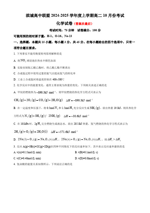
滨城高中联盟2024-2025学年度上学期高二10月份考试化学试卷(答案在最后)考试时间:75分钟试卷满分:100分可能用到的相对原子量:H-1、O-16、Na-23一、选择题:本题共15小题,每小题3分,共45分。
在每小题给出的四个选项中,只有一项符合题目要求。
1.下列事实不能用勒夏特列原理解释的是A.将2NO 球浸泡在热水中颜色加深B.实验室制取乙酸乙酯时,将乙酸乙酯不断蒸出C.合成氨过程中使用过量的氮气以提高氢气的转化率D.工业上合成氨时将温度控制在400~500℃2.化学反应中的能量变化,通常主要表现为热量的变化。
下列相关表述正确的是A.甲烷的燃烧热为1890.3kJ mol --⋅,则甲烷燃烧的热化学方程式可表示为()()()()4222CH g 2O g CO g 2H O g +=+1890.3kJ mol H -∆=-⋅B.在一定温度和压强下,将0.5mol 2N 和1.5mol 2H 充分反应生成()3NH g ,放出热量19.3kJ ,则其热化学方程式为()()()223N g 3H g 2NH g + 138.6kJ mol H -∆=-⋅C.在101kPa 时,2g 2H 完全燃烧生成液态水,放出285.8kJ 热量,氢气燃烧的热化学方程式表示为()()()2222H g O g 2H O l +=1571.6kJ mol H -∆=-⋅D.()()()22212Na l O g Na O s H +=∆,()()()22222Na s O g Na O s H +=∆,则12H H ∆>∆3.反应A(g)+3B(s)=2C(g)+2D(g)在四种不同情况下的反应速率如下,其中表示反应速率最快的是A.v(A)=0.15mol/(L·min) B.v(B)=0.1mol/(L·s)C.v(C)=0.40mol/(L·min)D.v(D)=0.0lmol/(L·s)4.氢卤酸的能量关系如图所示,下列说法正确的是A.已知HF 气体溶于水放热,则HF 的23456ΔH-ΔH -ΔH -ΔH -ΔH -ΔH <0B.相同条件下,HCl 的2ΔH 比HBr 的小C.相同条件下,HCl 的34ΔH +ΔH 比HI 的大D.5ΔH <05.在一定温度下的定容容器中,当下列哪些物理量不再发生变化时,表明反应()()()A s 2B g C g + ()D g +已达到平衡状态的个数有①混合气体的压强;②混合气体的密度;③B 的物质的量浓度;④混合气体的总物质的量;⑤混合气体的平均相对分子质量;⑥()C v 与()D v 的比值;⑦混合气体的总质量;⑧混合气体的总体积;⑨C 、D 的分子数之比为1∶1A.4个B.5个C.6个D.7个6.在一密闭容器中发生反应:()()()()2A g 2B g C s 3D g ++ H 0∆<,达到平衡时采取下列措施,可以使正反应速率增大、D 的物质的量浓度增大的是A.移走少量CB.升高温度C.缩小容积,增大压强D.容积不变,充入氦气7.下列说法错误的是A.合成氨反应采取循环操作主要是为了提高化学反应速率B.()33FeCl 3KSCN Fe SCN 3KCl ++ 在溶液中达平衡后,加少量KCl 固体,溶液颜色不变C.一定条件下,可逆反应()()2242NO g N O g 达到平衡后,保持容器温度和容积不变,再通入一定量2NO ,则再次达到平衡时2NO 的质量分数减小D.一定温度下,对()()()222BaO s 2BaO s O g + 平衡体系缩小体积,再次达到平衡时()2O c 不变8.下列是有关外界条件对化学反应速率或化学平衡影响的图像,其中图像和实验结论表达均正确的是图A 图B图C 图DA.()()()A g 3B g 2C g + 是其他条件一定时,反应速率随温度变化的图像,则H 0∆>B.()()()A g 3B gC g + H 0∆<,1t 时缩小体积增大了压强,平衡向正反应方向移动C.()()()A g 2B g 2C g + 是在有、无催化剂存在条件下,建立平衡过程的图像,曲线b 代表使用了催化剂D.()()()A g B g 2C g + 是一定条件下,向含有一定量A 的恒容密闭容器中逐渐加入B ,达平衡时A 的转化率的图像9.近年,我国科学家利用两种不同的纳米催化剂()3434Co O /Pt N Co O /Pt -、在室温水汽条件下实现高效CO 催化氧化161616221C O O C O 2⎛⎫+=⎪⎝⎭,其反应历程中相对能量的变化如图所示(TS1TS2TS3、、分别代表过渡态1、过渡态2、过渡态3),下列说法正确的是A.在该条件下,催化效果较好的催化剂是34N Co O /Pt -,故使用催化剂34N Co O /Pt -能提高反应物的转化率B.若利用182H O 进行同位素标记实验,检测到以上反应中有1618C O O 和182C O 生成,说明反应过程中有O H -键的断裂C.反应:161616221C O(g)O (g)C O (g)2=+的H 0∆<,该反应在低温时不能自发进行D.若ⅱ表示2H O 被吸附在催化剂表面,则34Co O /Pt 更容易吸附2H O 10.温度为T 时,在三个起始体积均为1L 的密闭容器中发生反应:()()()2232SO g O g 2SO g + 1197kJ mol -∆=-⋅H 。


成都市2020年高中阶段教育学校统一招生考试化学可能用到的相对原子质量:H-1 C-12 O-16 Ca-40第Ⅰ卷(选择题,共42分)一、选择题(本题包括14个小题,每小题3分,共42分。
每小题只有一个....选项符合题意)1.(2020四川成都中考,1,3分,★☆☆)下列成都出土的文物中,不.属于金属材料的是()A.东汉说唱俑B.“郫”字青铜戈C.龙纹铅饼币D.黄金面具2.(2020四川成都中考,2,3分,★☆☆)成都围绕“人、城、境、业”开展公园城市示范区建设,相关举措有误的是()A.简约适度、低碳生活B.城园相融、人城和谐C.水润天府、绿满蓉城D.减少污染、关停企业3.(2020四川成都中考,3,3分,★☆☆)根据下图实验,说法正确的是()A.品红的扩散速度相同B.浓氨水变红C.氨水显碱性,pH大于7 D.分子运动速率与温度无关4.(2020四川成都中考,4,3分,★☆☆)化学与健康息息相关。
下列说法正确的是()A.摄入足量的钙预防骨质疏松B.缺乏维生素A会引起坏血病C.工业用盐可代替食盐用于烹调D.必需微量元素只能用药物补充5.(2020四川成都中考,5,3分,★☆☆)有关下图实验的说法正确的是()A.红磷会燃烧,产生大量白烟B.向水中白磷通氧气,白磷会燃烧C.热水的作用只是提供热量D.可燃物温度达到着火点即可燃烧6.(2020四川成都中考,6,3分,★☆☆)下列物质的用途主要由物理性质决定的是()A.氧气用于医疗急救B.氦可用于制造低温环境C.一氧化碳用于炼铁D.天然气用作燃料7.(2020四川成都中考,7,3分,★☆☆)科学家因锂离子电池发展的研究获诺贝尔化学奖。
结合图示,有关锂的说法正确的是()A.属于非金属元素B.相对原子质量是6.941gC.表示核内有3个电子D.离子符号是Li+8.(2020四川成都中考,8,3分,★☆☆)下列化学用语表达正确的是()A.氟元素:F B.60个碳原子:C60C.KI:碘酸钾D.氯化钡:BaCl9.(2020四川成都中考,9,3分,★★☆)北京大学科研团队以炼钢废气为原料,实现了制备油品的新催化过程,反应过程如图所示。
威索燃烧器中文说明书(总43页)-CAL-FENGHAI.-(YICAI)-Company One1-CAL-本页仅作为文档封面,使用请直接删除安装使用说明书威索燃气燃烧器1-11号- weishaupt -证明在此我们说明,威索(-weishaupt-)燃气燃烧器符合下列EC标准的基本要求:90/396/EEC Gas Equipment Guideline89/336/EWG Electromagnetic Compatibility73/23/EEC Low Voltage Guideline因此燃烧器上带有CE/0085标记。
其它质量保证体系由DIN EN ISO 9001认可。
德国麦克斯·威索有限公司目录1. 一般说明.................................................................. 错误!未指定书签。
2. 燃烧器的安装.............................................................. 错误!未指定书签。
3. 气路示意图................................................................ 错误!未指定书签。
4. 阀门组件说明.............................................................. 错误!未指定书签。
5. 阀门组件的安装............................................................ 错误!未指定书签。
6. 阀门组件的气密性检验...................................................... 错误!未定义书签。
7. 功能流程检验.............................................................. 错误!未指定书签。

Designation:F1173–01An American National Standard Standard Specification forThermosetting Resin Fiberglass Pipe Systems to Be Usedfor Marine Applications1This standard is issued under thefixed designation F1173;the number immediately following the designation indicates the year oforiginal adoption or,in the case of revision,the year of last revision.A number in parentheses indicates the year of last reapproval.Asuperscript epsilon(e)indicates an editorial change since the last revision or reapproval.1.Scope1.1This specification covers reinforced thermosetting resin pipe systems with nominal pipe sizes(NPS)1through48in. (25through1200mm)which are to be used for allfluids approved by the authority having jurisdiction in marine piping systems.1.2Values stated in inch-pound are to be regarded as the standard.Values given in parentheses are for information only.1.3The dimensionless designator NPS has been substituted for traditional terms as“nominal diameter,”“size,”and“nomi-nal size.”1.4The following safety hazards caveat pertains to the test methods which are included in this specification.This standard does not purport to address all of the safety concerns,if any, associated with its use.It is the responsibility of the user of this standard to establish appropriate safety and health practices and determine the applicability of regulatory limitations prior to use.2.Referenced Documents2.1ASTM Standards:D883Terminology Relating to Plastics2D1598Test Method for Time-To-Failure of Plastic Pipe Under Constant Internal Pressure3D1599Test Method for Resistance to Short-Time Hydrau-lic Failure Pressure of Plastic Pipe,Tubing,and Fittings3 D2105Test Method for Longitudinal Tensile Properties of “Fiberglass”(Glass-Fiber-Reinforced Thermosetting-Resin)Pipe and Tube3D2310Classification for Machine-Made“Fiberglass”(Glass-Fiber-Reinforced Thermosetting-Resin)Pipe3D2584Test Method for Ignition Loss of Cured Reinforced Resins4D2924Test Method for External Pressure Resistance of “Fiberglass”(Glass-Fiber-Reinforced Thermosetting-Resin)Pipe3D2992Practice for Obtaining Hydrostatic or Pressure De-sign Basis for“Fiberglass”(Glass-Fiber-Reinforced Thermosetting-Resin)Pipe and Fittings3D3567Practice for Determining Dimensions of“Fiber-glass”(Glass-Fiber-Reinforced Thermosetting-Resin)Pipe and Fittings3D5028Test Method for Curing Properties of Pultrusion Resins by Thermal Analysis5D5686Specification for“Fiberglass”(Glass-Fiber-Reinforced Thermosetting-Resin)Pipe and Pipe Fittings, Adhesive Bonded Joint Type Epoxy Resin,for Condensate Return Lines3E1529Test Methods for Determining Effects of Large Hydrocarbon Pool Fires on Structural Members and As-semblies6F412Terminology Relating to Plastic Piping Systems3 2.2Other Documents:ANSI B16.1Cast Iron Pipe Flanges and Flanged Fittings7 ANSI B16.5Pipe Flanges and Flanged Fittings7IMO Resolution A.753(18)Guidelines for the Application of Plastic Pipes on Ships8NSF-619Code of Federal Regulations21CFR175.105, 21CFR177.2280,21CFR177.2410,and21CFR177.24208 Code of Federal Regulations Title46,Part56,for Piping Systems,and Subpart56.60-25for Nonmetallic Materials8 IMO Resolution A.653(16)Recommendation on Improved1This specification is under the jurisdiction of ASTM Committee F25on Ships and Marine Technology and is the direct responsibility of Subcommittee F25.13on Piping Systems.Current edition approved Dec.10,2001.Published April2002.Originally published as F1173–st previous edition F1173–95.2Annual Book of ASTM Standards,V ol08.01.3Annual Book of ASTM Standards,V ol08.04.4Annual Book of ASTM Standards,V ol08.02.5Annual Book of ASTM Standards,V ol08.03.6Annual Book of ASTM Standards,V ol04.07.7Available from American National Standards Institute,25W.43rd St.,4th Floor,New York,NY10036.8Available from Standardization Documents Order Desk,Bldg.4Section D,700 Robbins Ave.,Philadelphia,PA19111-5098,Attn:NPODS.9Available from the National Sanitation Foundation,P.O.Box130140,789N.Dixboro Rd.,Ann Arbor,MI48113-0140.1Copyright©ASTM International,100Barr Harbor Drive,PO Box C700,West Conshohocken,PA19428-2959,United States.Fire Test Procedures for Surface Flammability of Bulk-head,Ceiling,and Deck Finish Materials 8IMO Resolution MSC.61(67)International Code for Appli-cation of Fire Test Procedures 8OTI 95634Jet-Fire Resistance Test of Passive Fire Protec-tion Materials 102.3ISO Documents:900177573.Terminology3.1Definitions are in accordance with Terminologies D 883and F 412.3.2Definitions of Terms Specific to This Standard:3.2.1continuously electrically conductive ,adv —pipe and fittings made conductive using discretely conductive materials or layers.3.2.2homogeneously electrically conductive ,adv —pipe and fittings made conductive using a resin additive so that conductivity is maintained between any two points on the pipe or fitting.3.2.2.1Discussion —For conveying nonconducting fluids (those having conductance less than 1000pico-Siemens per metre),pipe systems which are continuously or homoge-neously conductive or have conductivity from the inside surface to the outside surface are recommended.In accordance with IMO Resolution A.753(18),all pipe located in a hazard-ous area,regardless of the fluid being conveyed,must be electrically conductive.3.2.3maximum operating pressure ,n —the highest pressure that can exist in a system or subsystem under normal operating conditions.3.2.4representative piping system ,n —a system composed of a single manufacturer’s pipes,fittings,joints,and adhesives that would normally be used by a customer or installer.4.Classification4.1General —Pipe and fittings are to be classified using the following system which is similar to that of Classification D 2310for pipe.4.1.1Types :4.1.1.1Type I —Filament wound.4.1.1.2Type II —Centrifugally cast.4.1.1.3Type III —Molded (fittings only).4.1.2Resin :4.1.2.1Resin 1—Epoxy resin.4.1.2.2Resin 2—Vinylester resin.4.1.2.3Resin 3—Polyester resin.4.1.2.4Resin 4—Phenolic resin.4.1.2.5Resin 5—Customer-specified resin.4.1.3Class :4.1.3.1Class A —No liner.4.1.3.2Class B —Reinforced liner.4.1.3.3Class C —Nonreinforced liner.4.2Pressure Rating —Pipe and fittings shall be classified asto the method used to obtain their pressure rating (refer to Appendix X1).4.2.1Rating Method 1—Short-term test.4.2.2Rating Method 2—Medium-term (1000-h)test.4.2.3Rating Method 3—Long-term (10000-h)test.4.2.4Rating Method 4—Long-term (10000-h)regression test.4.3Fire Endurance —Piping systems are to be classified in accordance with the following cells if fire performance is to be specified (refer to Appendix X2).4.3.1Fluid :4.3.1.1Fluid E —Empty.4.3.1.2Fluid EF —Initially empty for 5min,followed by flowing water.Fluid velocity of 3-ft/s maximum during quali-fication test.)4.3.1.3Fluid S —Stagnant water.4.3.2Fire Type :4.3.2.1Fire Type JF —Jet fire with heat flux between 95100and 126800Btu/(h-ft 2)(300and 400kW/m 2).4.3.2.2Fire Type IF —Impinging flame with heat flux of 36011Btu/(h-ft 2)(113.6kW/m 2).4.3.2.3Fire Type HF —Hydrocarbon furnace test at 2012°F (1100°C).4.3.3Integrity/Duration :4.3.3.1Integrity A —No leakage during or after fire test.4.3.3.2Integrity B —No leakage during fire test,except a slight weeping is acceptable.Capable of maintaining rated pressure for a minimum of 15min with a leakage rate of 0.05gal/min (0.2L/min)after cooling.4.3.3.3Integrity C —Minimal or no leakage (0.13gal/min (0.5L/min))during fire test.Capable of maintaining rated pressure with a customer-specified leakage rate after cooling.4.3.3.4Duration —The duration of the test shall be specified in minutes and shall be specified or approved by the authority having jurisdiction.5.Ordering Information5.1When ordering pipe and fittings under this specification,the following should be specified (where applicable):5.1.1Service Conditions :5.1.1.1Fluid being transported.5.1.1.2Design temperature (reference6.6).5.1.1.3Internal design pressure.5.1.1.4External design pressure.5.1.2General Information :5.1.2.1Type (reference 4.1.1).5.1.2.2Resin (reference 4.1.2).5.1.2.3Class (reference 4.1.3).5.1.3Pressure Rating Method (Internal Only)(reference 4.2).5.1.4Fire Endurance :5.1.4.1Fluid (reference 4.3.1).5.1.4.2Fire type (reference 4.3.2).5.1.4.3Integrity (reference 4.3.3).5.1.4.4Flame spread rating (reference6.4).5.1.4.5Smoke and other toxic products of combustion (reference6.5).5.1.5NPS.10Offshore Technology Information (OTI)Report is available from Health and Safety Executive,HSE Information Centre,Broad Ln.,Sheffield,S37HQ,U.K.5.1.6Manufacturer’s Identification(part number,product name,and so forth).5.1.7Specific job requirements(that is,potable water usage, electrical conductivity).6.Performance Requirements6.1Internal Pressure—All components included in the piping system shall have pressure ratings suitable for the intended service.Pressure ratings shall be determined in accordance with Appendix X1using the method specified by the customer or a longer-term method,if available.If,for example,a Rating Method2—medium-term test is specified and data for Rating Method3—long-term test is available,then the long-term test data is acceptable.Note that for some components,particularly specialtyfittings,long-term testing is not practical and ratings for these items will typically be determined using Rating Test Method1.6.2External Pressure—All pipe included in the piping system shall have external pressure ratings suitable for the intended service.External pressure ratings shall be determined by dividing the results of Test Method D2924by a minimum safety factor of3.6.3Fire Endurance—The piping system shall have thefire endurance required by the authority having jurisdiction based on the intended location and service.Fire endurance shall be determined using the appropriate method in Appendix X2. 6.4Flame Spread—The authority having jurisdiction shall designate anyflame spread requirements based on the location of the piping.For ships,mobile offshore drilling units (MODU’s),andfloating oil production platforms subject to the requirements of SOLAS or Title46of the U.S.Code of Federal Regulations,performance shall be determined by test proce-dures given in IMO Resolution MSC.61(67),Annex1,Part 5—Test for Surface Flammability,as modified for pipes in Appendix3of IMO Resolution A.753(18).6.5Smoke and Other Toxic Products of Combustion—The authority having jurisdiction shall designate any smoke and toxicity requirements based on the location of the piping.For ships,MODUs,andfloating oil production platforms subject to the requirements of SOLAS or Title46of the U.S.Code of Federal Regulations,performance shall be determined by test procedures given in IMO Resolution MSC.61(67),Annex1, Part2—Smoke and Toxicity Test,as modified in B.9.0of Appendix B—Fire Performance Tests.6.6Temperature—The maximum working temperature shall be at least36°F(20°C)less than the minimum glass transition temperature(determined in accordance with Test Method D5028or equivalent)or heat distortion temperature (determined in accordance with ISO75Method A,or equiva-lent)of the resin or plastic material.The minimum glass transition temperature or heat distortion temperature,which-ever is less,shall not be less than176°F(80°C).N OTE1—Glass transition temperature shall be used for in-process quality control testing(reference9.1.4,9.2.4,and9.3.3).6.7Material Compatibility—The piping material shall be chemically compatible with thefluid being carried and any fluid in which it will be immersed.6.8Electrical Resistance—Conductive piping systems shall have a resistance per unit length not to exceed3.053104V/ft (13105V/m)when tested in accordance with Appendix X3. Resistance to earth at any location on an installed piping system required to be conductive shall be no greater than13 106V.6.9Static Charge Shielding—Conductive piping systems shall have a maximum resulting voltage not to exceed1%of the supply voltage induced on the exterior surface of the pipe when tested in accordance with Appendix X3.6.10Potable Water Usage—The material,including pipe,fittings,adhesive,and any elastomeric gaskets required shall have no adverse effect on the health of personnel when used for potable water service.Material shall conform to National Sanitation Standard61or meet the requirements of FDA Regulations21CFR175.105and21CFR177.2280,21CFR 177.2410,or21CFR177.2420.7.Other Requirements7.1Flanges—Standardflanges shall have bolt patterns in accordance with ANSI B16.5Class150for nominal pipe sizes 24-in.and smaller and in accordance with ANSI B16.1Class 125for largerflanges.Consult the manufacturer’s literature for bolt length,torque specifications,and tightening sequence. 7.2Military Usage—Piping andfittings used in military applications shall comply with the provisions of Appendix D, Supplementary Requirements to Specification F1173for U.S. Navy use.8.Workmanship and Appearance8.1All pipe,fittings,and spools shall be visually inspected for compliance with the requirements stated in Table1,and,if appropriate,either repaired or rejected.After all minor repairs, a pressure test in accordance with9.1.1,9.2.1,or9.3.1shall be performed on the component.9.Inspection and Sampling9.1Pipe:9.1.1Pressure Tests—A minimum of5%of pipe joints shall be tested at a pressure of not less than1.5times the pipe system pressure rating.9.1.2Lot Size—A lot of pipe shall consist of150joints,or fractions thereof,of one size,wall thickness,and grade in continuous production.9.1.3Short-Term Burst Tests—Short-term hydrostatic burst tests shall be conducted in accordance with Test Method D1599at a minimum frequency of one test per lot.If the measured value is less than85%of the published value,the lot is rejected or subject to retest.9.1.4Degree of Cure—The glass transition temperature (Tg)shall be determined at a minimum frequency of one test per production lot.If the measured value is more than10°F less than the value in the manufacturer’s specification,the lot is rejected or subject to retest.9.1.5Glass Content—The glass content(mass fraction ex-pressed as percentage)of at least one sample per production lot shall be determined in accordance with Test Method D2584.If the measured glass content is not within5%of the value in the manufacturer’s specification,the lot is rejected or subject toretest.9.1.6Wall Thickness —Total wall thickness and reinforced wall thickness shall be determined in accordance with Practice D 3567once per every production lot.Total and reinforced wall thickness shall be as specified in Table 2.Any out of tolerance components shall be rejected and the remainder of the lot be subject to retest.9.2Fittings :9.2.1Pressure Tests —A minimum of 5%of each fitting lot shall be tested at a pressure of not less than 1.5times the pipe system pressure rating.All samples shall hold the test pressure for a minimum of 2min.9.2.2Lot Size —A lot shall consist of 50fittings or one day’s production of a specific fitting,whichever is greater.By agreement between the manufacturer,the purchaser,and the authority having jurisdiction,the lot size shall be permitted to be altered.9.2.3Short-Term Burst Tests —Short-term hydrostatic burst tests shall be conducted in accordance with Test Method D 1599at a minimum frequency of one test per lot.If themeasured value is less than 85%of the published value,the lot is rejected or subject to retest.9.2.4Degree of Cure —The Tg shall be determined at a minimum frequency of one test per production lot.If the measured value is more than 10°F less than the value in the manufacturer’s specification,the lot is rejected or subject to retest.9.2.5Glass Content —The glass content (mass fraction ex-pressed as percentage)of at least one sample per production lot shall be determined in accordance with Test Method D 2584.If the measured glass content is not within 5%of the value in the manufacturer’s specification,the lot is rejected or subject to retest.9.2.6Wall Thickness —Total wall thickness and reinforced wall thickness shall be determined in accordance with Practice D 3567once per every production lot.Total and reinforced wall thickness shall be as specified in Table 2.Any out of tolerance components shall be rejected.9.3Flanges and Mitered Fittings :9.3.1Pressure Tests —One mitered fitting from each lot shall be tested to a pressure equal to or greater than 1.5times the pipe system rating.All samples shall hold the pressure for a minimum of 2min.9.3.2Lot Size —A lot shall consist of 20flanges or 10mitered fittings of any given configuration.9.3.3Degree of Cure —The Tg shall be determined at a minimum frequency of one test per production lot.If the measured value is more than 10°F less than the value in the manufacturer’s specification,the lot is rejected or subject to retest.TABLE 1Visual Acceptance CriteriaDefect Type DescriptionAcceptance CriteriaCorrective Action Burnthermal decomposition indicated by distortion or discoloration of the laminate surfacenone permitted reject Chip small piece broken from edge or surface—if reinforcement fibers are broken,the damage is considered a crack if there are undamaged fibers exposed over any area;or nofibers are exposed but an area greater than 0.4by 0.4in.(10by 10mm)lacks resinminor repairif no fibers are exposed,and the area lacking resin is less than 0.4by 0.4in.(10by 10mm)accept Crack actual separation of the laminate which is visible on opposite surfaces and often extends through the wall;reinforcement fibers are often visible/brokennone permittedrejectCrazing fine hairline cracks at or under the surface of the laminate;white areas are not visiblecrack lengths greater than 1.0in (25.4mm)minor repair crack lengths less than 1.0in (25.4mm)accept Dry spot area of incomplete surface film where the reinforcement has not been wetted by resinnone permittedreject Fracture rupture of the laminate with complete penetration;majority of fibers broken;visible as lighter colored area of interlaminar separationnone permittedrejectInclusion foreign matter wound into the laminate none permitted in structural wall (treat same as pit if located atthe surface)reject Pit (pinhole)small crater in the surface of the laminate;width is on the same order of magnitude as the depth diameter greater than 0.032in.(0.8mm)or depth greater than10%of wall thickness,or bothminor repair diameter less than 0.032in.(0.8mm)and depth less than 10%of wall thicknessacceptRestriction excessive resin,adhesive,or foreign matter on the internal wall of pipe/fittingsnone permittedremove by careful grinding Wear scratch shallow mark caused by improper handling,storage,or transportation,or combination thereof—if reinforcement fibers are broken,the damage is considered to be a crackundamaged fibers exposed over any area or no fibers are exposed but an area greater than 0.4by 0.4in (10by 10mm)lacks resinminor repairno fibers exposed and the area lacking resin is less than 0.4by 0.4in.(10by 10mm)acceptTABLE 2Wall Thickness TolerancesN OTE —Where measurement of the reinforced wall thickness would cause destruction or damage to the part,only the total wall thickness measurement need be taken.DimensionTolerance,%Total wall thickness +22.5A −0Reinforced wall thickness+22.5A −0AThe tolerance on total and reinforced wall thickness for fittings shall refer to the manufacturer’s designated location on the body of thefitting.9.3.4Glass Content—The glass content(mass fraction ex-pressed as percentage)of at least one sample per production lot shall be determined in accordance with Test Method D2584.If the measured glass content is not within5%of the value in the manufacturer’s specification,the lot is rejected or subject to retest.9.3.5Wall Thickness—Total wall thickness and reinforced wall thickness shall be determined in accordance with Practice D3567once per every production lot.Total and reinforced wall thickness shall be as specified in Table2.Any out-of-tolerance components shall be rejected and the remainder of the lot be subject to retest.9.4Retest—If any test result in9.1,9.2,or9.3,or combi-nation thereof,fails to conform to the specified requirements, the manufacturer shall be permitted to elect to reject the entire lot,or retest two additional samples from the same lot.If both of the retest specimens conform to the requirements,all items in the lot shall be accepted except the sample which initially failed.If one or both of the retest samples fail to conform to the specified requirements,the manufacturer shall reject the entire lot or test individually the remaining samples in the lot in accordance with9.1.1,9.2.1,or9.3.1,as applicable.Note that in thefinal case,all samples need only be subjected to the tests that the original samples failed.9.5Production Quality Documentation—The manufacturer shall have manufacturing procedures for each component to be supplied,raw material test certificates for each component to be used in manufacturing,and production quality control reports available for the procurement officer.10.Certification10.1The pipe manufacturer shall be registered by an ac-credited agency to meet the requirements of ISO9001.For purposes of this specification,the manufacture shall be con-sidered a“special process”as defined in ISO9001,Section4.9.11.Product Marking11.1Pipe andfittings shall be marked with the name,brand, or trademark of the manufacturer;NPS;manufacture date; pressure rating;pressure rating method;and other information upon agreement between the manufacturer and the purchaser.12.Keywords12.1epoxy resinfittings;epoxy resin pipe;marine piping; nominal pipe size;thermoset epoxy resin pipeAPPENDIXES(Nonmandatory Information)X1.DETERMINATION OF INTERNAL PRESSURE RATING FOR PIPE,FITTINGS,AND JOINTSX1.1Internal pressure rating for a piping system shall be determined using one of four methods.The method used to determine this rating shall be clearly identified by the manu-facturer in published literature.X1.1.1Rating Method1—Short-Term Test Method—Two samples of each pipe,joint,fitting,or other component shall be tested in accordance with Test Method D1599at ambient temperature.The maximum rating for mitered(hand lay-up)fittings shall be determined by dividing the lesser result by a safety factor of5.0.The maximum rating for all other compo-nents shall be determined by dividing the lesser result by a safety factor of4.0.X1.1.2Rating Method2—Medium-Term(1000-h)Test—Two samples of each pipe,joint,fitting,or other component are to be tested in accordance with Test Method D1598for a period of1000h at the rated temperature.Both specimens must survive the exposure period without leakage.The maximum rating for mitered(hand lay-up)fittings shall be determined by dividing the test pressure by a safety factor of 2.5.The maximum rating for all other components shall be determined by dividing the test pressure by a safety factor of2.2.X1.1.3Rating Method3—Long-Term(10000-h)Test—Two samples of each pipe,joint,fitting or other component are to be tested in accordance with Test Method D1598for a period of 10000h at the rated temperature.Both specimens must survive the exposure period without leakage.The maximum rating for mitered(hand lay-up)fittings shall be determined by dividing the test pressure by a safety factor of2.0.The maximum rating for all other components shall be determined by dividing the test pressure by a safety factor of1.87.X1.1.4Rating Method4—Long-Term(10000-h)Regres-sion Test—Pipe,fittings,and joints shall be tested in accor-dance with Practice D2992Procedure B at the rated tempera-ture.The pressure rating for all components shall be determined in accordance with the hydrostatic design basis (HDB)and lower confidence limit(LCL)as calculated in the test method.Ratings shall be determined by dividing the LCL at20years by a factor of1.5.Scaling of the results is allowed for pipe bodies only in accordance with the ISO equation:S3SF5P~D2t r!/2t r(X1.1) where:S=hoop stress,psi(kPa),SF=service factor,D=mean reinforced diameter(OD−t)or(ID+t),in.(mm),P=internal pressure psig(kPa),andt r=minimum reinforced wall thickness,in.(mm).N OTE X1.1—Liner thickness is not to be used in determining inside diameter.N OTE X1.2—Coating thickness is not to be used in determining outsidediameter.X2.FIRE PERFORMANCE TESTSX2.1Fire performance tests shall be performed at an independent third-party laboratory to the satisfaction of the authority having jurisdiction.X2.2Piping Material Systems:X2.2.1Allfire endurance,flame spread,and smoke and toxicity testing,where required,shall be conducted on each piping material system.X2.2.2Changes in either the type,amount,or architecture, or combination thereof,of either the reinforcement materials, resin matrix,liners,coatings,or manufacturing processes shall require separate testing in accordance with the requirements of this specification.X2.3Fire-Protective Coatings:X2.3.1Where afire-protective coating is necessary for achieving thefire endurance,flame spread,or smoke and toxicity criteria,the following requirements apply:X2.3.1.1Pipes shall be delivered from the manufacturer with the protective coating on.On site application will be limited to what is physically necessary for installation(that is, joints).X2.3.1.2Thefire-protection properties(that is,fire endur-ance,flame spread,smoke production,and so forth)of the coating shall not be diminished when exposed to(1)salt water, oil,or bilge slops,(2)other environmental conditions such as high and low temperatures,high and low humidity,and ultraviolet rays,or(3)vibration.X2.3.1.3The adhesion qualities of the coating shall be such that the coating does notflake,chip,or powder,when subject to an adhesion test.X2.3.1.4Thefire-protective coating shall be resistant to impact and abrasion.It shall not be separated from the piping during normal handling.X2.4General Fire Endurance Test Requirements:X2.4.1All typical joints,including but not limited to pipe to pipe,fiberglassflange tofiberglassflange,andfiberglassflange to metallicflange intended to be used shall be tested.Elbows and tees need not be tested provided the same adhesive or method of joining utilized in straight piping tests will be used in the actual application.X2.4.2Qualification of piping systems of sizes different than those tested shall be allowed as provided for in Table X2.1.This applies to all pipe,fittings,system joints(including joints between metal andfiberglass pipes andfittings),methods of joining,and any internal or external liners,coverings,and coatings required to comply with the performance criteria.X2.4.3No alterations to couplings,fittings,joints,fasteners, insulation,or other components shall be made after the commencement of thefire endurance testing.Flange bolts shall not be retorqued after completion of thefire exposure testing, before hydrostatic testing.Postfire hydrostatic testing shall be conducted without altering the component in any way.X2.5Fire Type JF–Jet Fire—This test is based upon Health &Safety Executive document OTI95634,except that is modified so that actual pipe,joints,andfittings are exposed to theflame.X2.5.1Equipment:X2.5.1.1A propane vaporization and propulsion system capable of delivering0.6660.11lb/s(0.360.05kg/s)flow under controlled conditions into a backing“box”which has the test specimen mounted at the box’s front opening.The nozzle shall be a tapered,converging type,7.875in.(200mm)in length with an inlet diameter of2.0in.(52mm)and an outlet diameter of0.70in.(17.8mm).The nozzle is to be located 3.281ft(1.0m)from the front of the box,centered across the box,and mounted horizontally between15in.(375mm)and 30in.(750mm)from the bottom of the box.Theflow shall directly impinge on the test specimen.X2.5.1.2Water-handling and timing equipment suitable for delivering sufficient quantities of water to produce afluid velocity of3ft/s(0.91m/s)at the rated pressure of the piping system being tested.X2.5.1.3Instrumentation to record fuelflow rate,water flow rate,temperatures in the specimen and in various loca-tions in the backing panel,and water leakage rate from the pipe assembly or individual components.X2.5.2Test Specimen—The test specimen shall be prepared with the joints,fittings,andfire-protection coverings,if any, intended for use in the proposed application.It is up to the authority having jurisdiction to determine the number and size of test specimens,as well as requirements for the qualification of a range of pipe diameters.X2.5.3Test Conditions:X2.5.3.1Iffire-protective coatings or coverings contain or are liable to absorb moisture,the test specimen shall not be tested until the insulation has reached an air-dry condition.This condition is defined as equilibrium with an ambient tempera-ture at50%relative humidity of70610°F(2065°C).Where fire-protective coatings or coverings are required to enable a pipe system to pass afire endurance test,the coatings’or coverings’properties should not degrade over time or due to exposure to the environment as discussed in IMO FTP Code Res A.753(18)Paragraph2.2.6,or both.X2.5.3.2The test specimen shall be planar and shall be mountedflush to the opening of a5by5-ft(1.5by1.5-m) open-ended,steel box(closed back panel with a depth of1.64 ft(0.5m).Suitable auxiliary equipment shall be attached to the box to ensure the box’s structural stability and to prevent any transient ambient conditions from significantly affecting theTABLE X2.1Qualification of Piping Systems of Different SizesSize Tested[NPS],in.(mm)Minimum Size Approved,in.(mm)Maximum Size Approved,in.(mm)0to1.5(0to40)size tested size tested 2to4(50to100)size tested4(100)5to10(125to250)size tested10(250) 12to22(300to550)size tested22(550) 24to34(600to850)size tested34(850) 36to48(900to1200)size tested48(1200)。
花都区2025届高三年级调研考试化学试题本试卷分第Ⅰ巻(选择题)和第Ⅰ卷(非选择题)两部分,满分100分。
考试时间75分钟。
注意事项:1.答题前,考生务必用黑色字迹的钢笔或签字笔将自己的学校、班级、姓名、考生号填写在答题卡上,并用2B 铅笔把对应考生号标号涂黑。
2.选择题每小题选出答案后,用2B 铅笔把答题卡上对应题目的答案标号涂黑,如需改动,先用橡皮擦干净后,再选涂其他答案;不能答在试卷上。
3.非选择题必须用黑色字迹钢笔或签宇笔作答,答案必须写在答题卡各题目指定区域内的相应位置上;如需改动,先划掉原来的答案,再写上新的答案,改动的内容也不能超出指定的区域;不准使用铅笔、圆珠笔和涂改液。
不按以上要求作答的答案无效。
4,考生必须保持答题卡的整洁。
考试结束后,将答题卡交回。
5.可能使用的相对原子质量:H:1 He:4 C:12 N:14 O:16 Na:23 P:31 S:32 Cl:35.5 Mn:55 Fe:56 As:75 Mo:96 Ba:137 Ce:140一、选择题:本题共16小题,共44分。
第1~10小题,每小题2分;第11~16小题,每小题4分。
在每小题给出的四个选项中,只有一项是符合题目要求的。
1.近年假期,人文考古游持续成为热点。
很多珍贵文物都记载着中华文明的灿烂成就,具有深邃的文化寓意和极高的学术价值。
下列文物主要由合金材料制成的是( )A .西周兽面纹青铜盉B .东汉陶船模型C .明和田玉D .广彩开光外国风景图大碗2.“回望飞天路,逐梦新征程”。
下列说法正确的是( )A .月球中的与地球上的互为同位素B .“太空快递小哥”天舟六号壳体材料主要为铝合金,其强度大于纯铝C .“问天”实验舱使用砷化镓(GaAs )太阳能电池,其中As 位于周期表的d 区D .长征七号遥七运载火箭采用液氧、煤油等燃料作为推进剂,液氧和煤油均属于泥合物3.化学处处呈现美。
下列叙述不正确的是( )A .丝细洁白丝滑,其主要成分属于蛋白质B .燃放五彩缤纷的烟火,焰色试验属于化学变化C .干冰舞台美轮美奂,属于由极性键构成的非极性分子D .缺角的氯化钠晶体在饱和NaCl 溶液中慢慢变为完美的立方体块,体现晶体的自范性、4.《天工开物》中记载:“凡鸟金纸由苏杭造,其纸用东海巨竹膜为质。
DG10-B固体燃烧速率试验仪
设备名称 DG10-B固体燃烧速率试验仪
用途
本仪器用于确定物质传播燃烧的能力,将物质点燃后确定燃烧时间,
适用于颗粒状、糊状或粉状物质。
标准
符合联合国《关于危险货物运输的建议书·试验和标准手册》
33.2.1.4易燃固体的试验方法、GB/T 21618-2008《危险品 易燃固
体燃烧速率试验方法》和NYT 1860.15-2010 《农药理化性质测定试
验导则》第15部分:固体可燃性
技术参数 1. *兼容预筛分试验,适应固体粉末和金属粉末试样检测 2. 测试样品:粉状、粒状或膏状物质 3. *燃烧检测方式:全自动红外火焰检测 4. 燃烧检测行程:0~250mm 5. 燃烧距离测量精度:±0.5mm 6. 燃烧速率检测范围:0~1000mm/s 7. 点火源温度:≥1000℃
8. 点火方式: 电子点火器/气体点火器
9. 计时精度:±0.01s
10. 制样模具:长260mm,宽20mm,剖面为内高10mm的三角形模具
11. 承烧板:耐高温、不渗透、低导热
12. 10英寸工业平板电脑,配电容式触摸屏
13. 操作系统:Windows7专业版
功能特点 1. 兼容预筛分试验,适应固体粉末和金属粉末试样检测; 2. 全自动红外火焰检测技术,可靠检测明火及阴燃现象,保证检测精确度; 3. 配备标准堆垛模具,操作便捷;
4. 设备具有自检和报警功能,试验完成自动声光提醒;
5. 试验过程全自动化,支持参数设置、数据存储、查看报表等功能;
6. 自动记录原始数据,自动判断试验结果;
7. 底部配备有刹车功能的平板脚轮,便于搬运;
8. 采用10英寸工业平板电脑,配电容式触摸屏、Windows7专业版
操作系统,实时显示试验数据;
9. 支持网络连接,实现远程操控和数据传输。