2 V70产品功能-简篇
- 格式:pptx
- 大小:109.94 MB
- 文档页数:101


elsky1037fs-2c说明书(实用版)目录1.产品概述2.产品特性3.安装与使用4.维护与保养5.安全注意事项6.联系我们正文【产品概述】elsky1037fs-2c 是一款先进的电子产品,它具有强大的功能和出色的性能。
该产品专为满足用户的各种需求而设计,可以广泛应用于家庭、办公室和各种行业领域。
【产品特性】elsky1037fs-2c 具有以下特性:1.高效能:该产品采用先进的技术和优质的材料制造,具有出色的性能和稳定的运行。
2.多功能:elsky1037fs-2c 具备多种功能,可以满足用户的各种需求。
3.易操作:该产品设计简洁,操作方便,即使是初学者也能轻松掌握。
4.高品质:elsky1037fs-2c 采用高品质的材料和零部件,确保产品的使用寿命和性能。
【安装与使用】1.安装:在安装 elsky1037fs-2c 之前,请确保您已经阅读了说明书并了解了安装步骤。
按照安装指南进行操作,确保产品安装正确。
2.使用:使用 elsky1037fs-2c 时,请遵循产品说明书中的操作步骤。
在使用过程中,请注意保持产品的清洁和维护。
【维护与保养】为了确保 elsky1037fs-2c 的正常运行和延长使用寿命,请定期进行维护和保养。
具体方法如下:1.清洁:使用柔软的布轻轻擦拭产品表面,确保产品保持清洁。
2.检查:定期检查产品的各个部件,确保连接处紧固,无松动现象。
3.升级:如需升级产品,请务必联系专业人士进行操作。
【安全注意事项】在使用 elsky1037fs-2c 时,请注意以下安全事项:1.请勿在潮湿的环境中使用产品,以防止触电。
2.请勿将产品暴露在高温或阳光直射的环境中,以免损坏产品。
3.请勿让儿童单独使用产品,以防止意外发生。
【联系我们】如果您在使用 elsky1037fs-2c 过程中遇到任何问题,或有任何建议和需求,请随时联系我们。
第1页共1页。
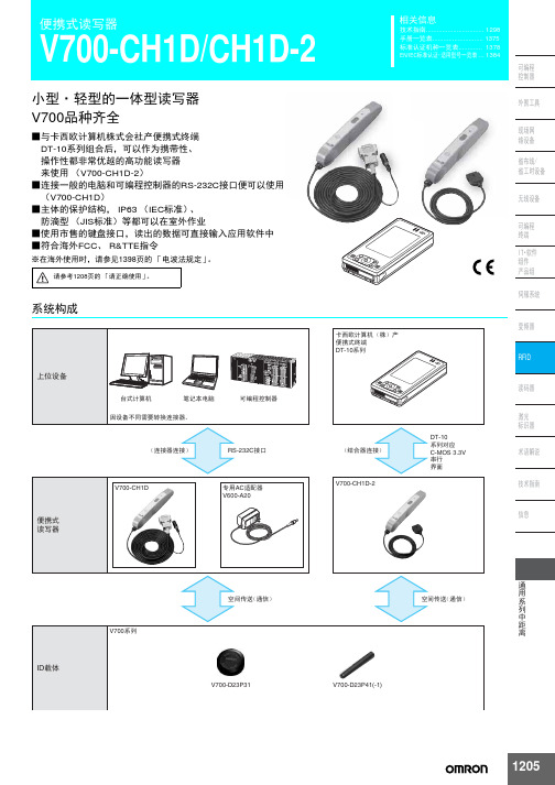
1205相关信息技术指南................................ 1298手册一览表............................ 1375标准认证机种一览表............. 1378EN/IEC 标准认证・适用型号一览表 (1384)便携式读写器V700-CH1D/CH1D-2小型・轻型的一体型读写器V700品种齐全■与卡西欧计算机株式会社产便携式终端DT-10系列组合后,可以作为携带性、操作性都非常优越的高功能读写器来使用(V700-CH1D-2)■连接一般的电脑和可编程控制器的RS-232C 接口便可以使用(V700-CH1D )■主体的保护结构,IP63(IEC 标准)、防滴型(JIS 标准)等都可以在室外作业■使用市售的键盘接口,读出的数据可直接输入应用软件中■符合海外FCC 、R&TTE 指令※在海外使用时,请参见1398页的「电波法规定」。
系统构成请参考1208页的「请正确使用」。
V700-CH1D1206通用系列中距离V700-CH1D/CH1D-2种类额定值/性能*连接器部除外。
此外,主体无耐药品性、耐油性。
上位通信界面规格*由设定模式设定。
名称型号便携式读写器(RS-232C 类型)V700-CH1D 便携式读写器(DT-10系列用)V700-CH1D-2AC 适配器V600-A20便携式读写器项目型号V700-CH1DV700-CH1D-2电源电压DC5V ±5% 由专用AC 适配器(V600-A20)提供DC5V ±5%(由DT-10主体提供)消耗功率50mA 以下连续使用时间——绝缘电阻50M Ω以上(DC500V )电缆端子一起和外壳之间测量耐电压AC1,000V 50/60Hz 1minAC1,000V(1分钟)电缆端子一起和外壳之间施加漏电流1mA 以下使用环境温度-10~+55℃(不结冰)使用环境湿度25~85%RH (不结露)使用周围环境应无腐蚀性气体保存环境温度-25~+65℃(不结冰)保护结构IEC 标准 IP63 *材质ABS 树脂(外壳) 、PET 树脂(铭牌)电缆长 2.5m 0.8m 重量约150g约90g专用AC 适配器(V600-A20)额定输入电压AC100V 50/60Hz 允许输入电压AC85~110V 50/60Hz 额定输入容量8VA使用环境温度-10~+55℃保存环境温度-20~+70℃绝缘电阻100M Ω 以上耐电压AC1,200V 以上质量约360g项目型号V700-CH1D V700-CH1D-2连接器规格D-SUB 9芯 (适合DOS/V 机)卡西欧计算机株式会社产DT-10专用26芯连接器依据标准RS-232C C-MOS 3.3V 串行接口传送路连接1对1通信方式2线式半双工同步方式起停同步(停止位=1或者2)*传送速度9,600bps 传送伐码ASCII 代码(7单位)或者JIS8单位导线*通信控制程序欧姆龙专用1对1程序误检测垂直奇偶(偶数/奇数/没有)*1207通用系列中距离V700-CH1D/CH1D-2功能说明・读取和写入数据时,只需靠近ID 载体咔嗒一声按下启动按钮便可读取ID 载体内保存的任意数据或写入数据。

欢迎您使用联想产品。
在第一次安装和使用本产品之前,请您务必仔细阅读随机配送的所有资料,这会有助于您更好地使用本产品。
如果您未按本手册的说明及要求操作本产品,或因错误理解等原因误操作本产品,联想移动通信科技有限公司将不对由此而导致的任何损失承担责任,但联想专业维修人员错误安装或操作过程中引起的损失除外。
联想移动通信科技有限公司已经对本手册进行了严格仔细的校勘和核对,但我们不能保证本手册完全没有任何错误和疏漏。
联想移动通信科技有限公司致力于不断改进产品功能、提高服务质量,因此保留对本手册中所描述的任何产品和软件程序以及本手册的内容进行更改而不预先另行通知的权利。
本手册的用途在于帮助您正确地使用联想产品,并不代表对本产品的软硬件配置的任何说明。
有关产品配置情况,请查阅与本产品相关合约(若有),或咨询向您出售产品的销售商。
本手册中的图片仅供参考,如果有个别图片与产品实物不符,请以产品实物为准。
本手册中介绍的许多网络功能是由网络服务商提供的特殊服务,能否使用这些网络功能取决于给您提供服务的网络服务商。
本手册内容受著作权法律法规保护,未经联想移动通信科技有限公司事先书面授权,您不得以任何方式复制、抄录本手册,或将本手册以任何形式在任何有线或无线网络中进行传输,或将本手册翻译成任何文字。
“联想”和“lenovo”是联想(北京)有限公司所有并授权联想移动通信科技有限公司使用的注册商标或商标。
本手册内所述及的其他名称与产品可能是联想或其他公司的注册商标或商标。
如果您在使用过程中发现本产品的实际情况与本手册有不一致之处,或您想得到最新的信息,或您有任何问题或想法,请垂询或登陆:售前咨询电话:800-810-8888阳光服务电话:010-82879600,************阳光服务网站:联想移动网站:2目录第1章安全和维护---------------------------------------------------------------------7第2章使用前-------------------------------------------------------------------------10 2.1手机外观 (10)2.2按键说明 (11)2.3显示屏 (12)2.4图标 (13)2.5电池 (14)2.5.1 电池的拆卸和安装 (14)2.5.2 电池的充电 (15)2.6连接网络 (17)2.6.1 SIM卡 (17)2.6.2 SIM卡的插入和取出 (17)2.6.3 开关手机 (18)2.6.4 手机解锁 (18)2.6.5 SIM卡解锁 (19)2.6.6 连接到网络 (19)2.7存储卡 (20)第3章快速使用指南----------------------------------------------------------------22 3.1特色功能 (22)3.2功能热键 (23)3.3拨打电话 (24)3.3.1 直接拨号 (24)3.3.2 拨打固定电话分机 (24)3.3.3 拨打国际电话 (24)3.3.4 拨打列表中电话 (24)3.4紧急呼叫 (25)3.5接听/拒接来电 (25)3.6结束通话 (25)3.7通话中选项 (25)3.8拨打第二个电话 (26)3.9接听第二个来电 (26)第4章功能菜单----------------------------------------------------------------------2834.3.1 写信息 (33)4.3.2 收件箱 (35)4.3.3 发件箱 (37)4.3.4 草稿箱 (39)4.3.5 聊天 (40)4.3.6 预约短信 (40)4.3.7 清空信箱 (41)4.3.8 信息模板 (41)4.3.9 小区广播 (41)4.3.10 语音信箱 (42)4.3.11 信息设置 (42)4.3.12 容量查看 (43)4.4电话簿 (43)4.4.1 快速查找 (43)4.4.2 姓名查找 (44)4.4.3 添加号码 (44)4.4.4 全部复制 (45)4.4.5 删除 (45)4.4.6 来电群组 (45)4.4.7 本机号码 (46)4.4.8 设置 (46)4.4.9 来电大头贴 (46)4.4.10 来电铃声 (46)4.4.11 来电影片 (46)4.5通话记录 (47)4.5.1 未接电话 (47)4.5.2 已接电话 (47)4.5.3 已拨电话 (47)44.6手机设置 (49)4.6.1 情景模式 (49)4.6.2 显示设置 (50)4.6.3 系统设置 (51)4.6.4 通话设置 (53)4.6.5 关闭通讯功能 (56)4.6.6 快捷菜单设置 (56)4.6.7 安全设置 (56)4.6.8 网络设置 (58)4.6.9 连接设置 (59)4.6.10 恢复出厂设置 (60)4.7我的文档 (60)4.8娱乐多媒体 (62)4.8.1 音乐播放器 (62)4.8.2 视频播放器 (63)4.8.3 照相机 (64)4.8.4 摄像机 (65)4.8.5 电子书 (65)4.8.6 游戏天地 (66)4.8.7 相簿 (66)4.8.8 照片艺术家 (67)4.8.9 自编铃声 (67)4.9工具箱 (68)4.9.1 闹钟 (68)4.9.2 日历行程 (68)4.9.3 计算器 (69)4.9.4 录音器 (69)4.9.5 备忘录 (70)54.9.12 STK* (72)4.10互联网 (72)4.10.1 浏览器 (72)4.10.2 电子邮件 (74)4.11联想空间 (77)第5章输入法-------------------------------------------------------------------------78 5.1概述 (78)5.2输入法说明 (78)5.2.1 智能拼音输入法 (78)5.2.2 笔画输入法 (80)5.2.3 智能英文输入法 (81)5.2.4 英文输入法 (82)5.2.5 数字输入法 (83)5.3中文输入示例 (83)第6章常见问题----------------------------------------------------------------------84第7章名词解释----------------------------------------------------------------------86第8章技术参数----------------------------------------------------------------------876第1章安全和维护使用手机时,请遵循以下注意事项。


Costs, workflow, quality, network performance, and customer experience are critical for the success of today’s fiber optic networks. Selecting the right test tools has become key toward meeting these needs. The Viavi Solutions™ T-BERD/ MTS-2000 is a handheld multi-test platform that provides field technicians with a single handheld unit to install, turn-up and maintain these networks to the highest standards.Its innovative design and hands-free bag ensure that all essential fiber test tools are close at hand, whatever the job or location. A large color screen with graphical user interface drives simple operation and optimal workflow in the field.T est capabilities include a range of OTDR modules for multimode and single-mode testing, as well as a range of FiberComplete™ modules for automated insertion loss/optical return Loss (IL/ORL), and fault finding. Both OTDR and FiberComplete modules are passive optical network (PON) optimized. The unit is also ready for connector end face pass/fail analysis to IEC standards with a digital analysis microscope.The PON power meter and CWDM-OSA modules also enable turn-up and troubleshooting of PON and coarse wavelength division multiplexing (CWDM) networks.Key Benefitsy Certify the fiber physical layer on FTT x/ PON, access, metro and enterprise networks y Ensure the highest-quality connectorizing, splicing, and turn-up of new fiber linksy Improve workflow with hands-free solution, driving best practices to IEC standardsy Smarter and faster field testing with simple setup and instantaneous pass/fail resultsy Boost productivity with improved report generation and flexible connectivityy Decrease OpEx and increase field productivity when combined with StrataSync™, cloud-enabled software that displays assets, modules, versions, and locations; maintains accurate instrument configuration and setup; and, provides visibility into instrument utilization and test-data managementApplicationsy High-visibility touch-screen displayy Field-installable modulesy Wide range of OTDR modules including Quad and PONy FiberComplete automated IL/ORL, PON power meter, and CWDM analyzery Automated fiber inspection and IEC pass/fail analysisy Optional built-in optical power meter, visual fault locator (VFL), and optical talk sety New-generation lithium polymer (LiPo) battery for 8-hour operationy Flexible connectivity with Ethernet, USB, Bluetooth®, and WiFi capabilitiesy Special hands-free bag standardy Cross-compatible with T-BERD/MTS-4000T-BERD®/MTS-2000 Handheld Modular Test SetFiber Optic Multitest Tool for Smarter, FasterField TestingWidest Range of Applications for Maximum FlexibilityThe T-BERD/MTS-2000 provides the largest range of test capabilities offered in one handheld unit. The modular design allows service providers the maximum flexibility to scale their investment and evolve with the growth of their network.The instrument supports the whole range of essential fiber analysis tools including connection inspection, connection check, source, ORL, OTDR, a power meter, a PON selective power meter, and CWDM optical spectrum analyzer.Application modules used with the T-BERD/MTS-2000 can also be used with the T-BERD/MTS-4000 and the two products are interoperable.Boosted Productivity with Seamless Data WorkflowThe T-BERD/MTS-2000 integrates various communication capabilities allowing remote control, data and setup uploads/downloads, and report transfer. The unit has one high-speed 1G Ethernet port, three USB ports, and optional WiFi and Bluetooth network connections.Test and create reportData and report storagePost-processing Remote coachingUpload files Remote controlTransfer to PC, tablets, PDAs, smartphones, andother devices2122171920181389345672© 2015 Viavi Solutions, Inc.Product specifications and descriptions in this document are subject to change without notice.t-berd-mts-2000-ds-fop-tm-ae 30168463 905 0115Contact Us +1 844 GO VIAVI (+1 844 468 4284)To reach the Viavi office nearest you, visit /contacts.Ordering InformationSpecificationsStrataSync — Empower Y our AssetsStrataSync is a hosted, cloud-enabled solution that provides asset, configuration, and test-data management of Viavi instruments and ensures that all have the latest software and options installed. StrataSync manages inventory , test results, and performance data anywhere with browser-based ease and improves technician and instrument efficiency. StrataSync manages and tracks test instruments, collects and analyzes results from the entire network, and informs andtrains the workforce.1. At 25°C, after 20 minutes stabilization time and after zero setting.2. At calibrated wavelength (except 1650 nm)3. –45 dBm from 800 to 1250 nm。
产品手册思科 Webex Room 70思科 Webex Room 70 Single思科 Webex Room 70 Dual思科Webex Room 70是思科Webex Room系列产品组合中的旗舰款视频协作产品。
包含两款配置:70英寸4K LED单显示屏的Room 70 Single (70S),用于打造以人为本的使用体验;70英寸4K LED双显示屏的Room 70 Dual (70D),用于打造以人为本以及以人或内容为本的使用体验。
这两款系统通过一体化解决方案将美观设计和强大功能融合在一起,非常适合大中型会议室使用。
无论要组织世界各地团队参与的会议,还是组织本地会议,Room 70都能帮助您把会议空间转化为一个强大的视频协作中心。
思科 Webex Room 70概述思科Webex™Room 70系列为客户带来无与伦比的视频和音频体验,完美契合了他们对于思科产品的预期。
此外,该系列产品还通过一系列全新功能,让会议、数据共享以及会议室和设备的集成更加智能化,从而进一步消除了大中型会议室在使用和部署视频解决方案时遇到的一系列障碍。
和Webex Room系列其他终端一样,Webex Room70在设计上亦精雕细琢,斩获了“红点设计大奖”(Red Dot Design Award)。
Room 70包含以下组件:一款功能强大的编解码器、内置Quad Cam,以及集成了高保真扬声器和语音跟踪麦克风的70英寸单/双4K超高清显示屏,非常适用于大中型会议室。
它通过一系列先进的摄像机技术为大中型会议室部署发言者跟踪功能和自动取景功能。
尽管这款产品具备颇为丰富的功能性和用户体验,但在价格和设计方面却展现出很大的灵活性,能满足各种会议室和会议空间的需求–您可在企业内部完成注册,或通过思科®协作云将其注册到思科Webex平台。
图 1. 落地安装的思科 Webex Room 70D和Webex Room 70S思科 Webex Room 70的特性和优势特性优势设计功能●精妙而含蓄的工业设计斩获 2017 年“红点设计大奖”(Red Dot Design Award) 的创新设计奖。
产品手册WBOX-5760,无风扇工业计算机版本:V1.01 / 41认可声明AMI 为Award Software International, Inc. 的商标。
Intel 和Atom 为Intel Corporation 的商标。
IBM、PC/AT、PS/2 和VGA 为International Business Machines Corporation的标。
Intel 和Atom 为Intel Corporation 的商标。
Microsoft Windows 为Microsoft Corp. 的注册商标。
RTL 为Realtek Semiconductor Co., Ltd. 的商标。
所有其它产品名称和商标均为其所有者的财产。
本手册适用于WBOX-5760系列.符合性声明这些限制旨在为商业环境下的系统操作提供合理保护,使其免受有害干扰。
本设备会产生、使用和发射无线电频率能量。
如果没有按照手册说明正确安装和使用,可能对无线电通讯造成有害干扰。
但即使按照手册说明进行安装和使用,也并不能保证不会产生干扰。
若本设备会对无线电或电视信号接收产生有害干扰,用户可通过开、关设备进行确认。
当本设备产生有害干扰时,用户可采取下面的措施来解决干扰问题:●1、调整接收天线的方向或位置●2、增大本设备与接收器之间的距离●3、将本设备的电源接头插在与接收器使用不同电路的电源插座●4、若需技术支持,请咨询经销商或经验丰富的无线电/电视技术人员警告!权利可能会被取消。
包装清单在您打开包装时,请确认包装中附有以下各项:●–WBOX-5760 1pcs附件盒,装有以下各项:●- 电源端子1pcs●- 国标电源线1.8米(可选)1pcs●- 电源适配器(可选)1pcs如果其中任何一项缺失或者破损,请立即联系您的销售商或销售代表。
2 / 41选购信息技术支持与服务用户若需技术支持,请与当地分销商、销售代表客服中心联系。
进行技术咨询前,用户须将下面各项产品信息收集完整:–产品名称及序列号–外围附加设备的描述–用户软件的描述(操作系统、版本、应用软件等)–产品所出现问题的完整描述–每条错误信息的完整内容警告! 1. 输入电压为DC 12-24V电源(电源功率90W或以上)2. 包装:需谨慎,请以双手托住设备。
Benefits•Automatic setup•Automatic valve recognition•Automatic selection of tolerance band•Fast Auto,Live and Flex Setup•360-degree LED indication•Burst seat clean•Exchangeable(threaded)air-fittings•Interchangeable with ThinkTop classicsWorking principlesThe control unit offers a single sensor solution for diaphragm,butterfly, single-seat and mixproof valves and it can befitted with up to three solenoid valves.ThinkTop converts the electrical PLC output signals into mechanical energy to energise,or de-energise,the air-operated valve,using the physical sensor target mounted on the valve stem. Installation with Auto Setup or Live Setup is intuitive and fast.To initiate Auto Setup,simply press the“SELECT”button and thenthe“ENTER”button to begin the setup sequence.The process is completed in accordance with the number of solenoid valvesfitted to the control unit.Alternatively,the ThinkTop can be set up,without dismantling the control head,using the built-in Live Setup feature for remote-configurationDimensional drawingsThinkTop V50mm Inch mm Inch A123 4.84A164 6.45 B105 4.13B105 4.13 C2007.87C2509.84 D150 5.91D170 6.69Technical dataMaterialPlastic parts Nylon PA12 Steel parts 1.4301/304 Airfittings Nickel plated/Nylon PA6 Gaskets Nitril/NBREnvironmentWorking temperature-10°C to+60°C Protection class(IP)IP66,IP67and IP69K Protection class(NEMA)4,4X and6PControl boardCommunication See interfaces section Sensor accuracy±0,1mm Stroke length0.1-104mm Mean Time To Failure(MTTF)224years Approved UL/CSASolenoid valveSupply voltage24VDC±10% Nominal power0,3W Air supply300-900kPa(3-9bar) Type of solenoids3/2-ways or5/2-way Number of solenoids0-3 Manual hold override Yes Air pressure6-8bar Air quality Class3,3,3acc.DIN ISO8573-1 Mean Time To Failure(MTTF)224years Recommendation Operate once a month to prevent dry-outAirfittingThrottle function air inlet/outlet0-100% Threaded airfitting G1/86mm(Rim blue)or1/4"(Rim Grey) Elbow push-infittings6mm(Rim blue)or1/4"(Rim Grey)Cable connectionMain cable gland entry Digital M16(ø4-ø10mm) Main cable gland entry AS-I M16(ø2-ø7mm)(0,08"-0,28") Seat lift sensor cable gland entry M12(ø3,5-ø7mm)(0,14"-0,28") Max wire diameter0.75mm2(AWG20)Vibration18Hz-1kHz@7,54g RMS Shock100gDrop testConstant humidity+40°C,21days,93%R.H. Cyclic humidity(working)-25°C/+55°C,12cyclesAccessoriesSeat lift sensor kitAirfitting for air throttle functionCertificationsOperational dataLED indicationThinkTop features a360-degree light guide.When the sensor target is within the respective setup position band,the corresponding colour lights up.Valve positionAll Main valve open Upper seat lift Lower seat pushActuatorDe-energised Energised Energised EnergisedBetween Not setupFactory settingGreenflashing Whiteflashing Blueflashing Yellowflashing offOperation Green White Blue Yellow off ThinkTop V ModeNot OK Green/redflashing White/redflashing Blue/redflashing Yellow/redflashing Red lashingAuto setupAuto Setup is a rule-based function.If one of these rules are not present,Flex Setup must be used.By default,ThinkTop V50and V70uses the de-energised/energised paradigm for valve positions feedback.3.9.3Overview of connectors and portsa Solenoid valve connectorb Indication lampc Main terminalsa Diagnostic Portb Seat lift sensor terminalbBurst clean modeBurst seat clean mode is available for ThinkTop V70and can be enabled when a ThinkTop V70with2or3solenoid valves is setup successfully using Auto SetupThe burst seat clean mode is enabled or disabled on the ThinkTop V70control board.Press"SELECT"(4times)until LED no4flashes,and then press ’ENTER"to enable or disable.This option is also available as an IO-Link parameterThe burst seat clean option is from factory disabled by default.However,if it is enabled and there is a manual reset to factory default,the burst seat clean option is disabled.Bust clean mode output diagrama Input(from PLC)b Positionc Solenoid valve outputd Output(both visual and electrical)e Positionreached adcbe eWhen the PLC input signal for either upper or lower seat push(Usl,Lsp)goes high,the respective solenoid valve is Energised.As soon as the sensor target reaches the predefined energised valve position,the solenoid valve is automatically de-energised by the ThinkTop V70.A two-second electrical and visual feedback(t)is provided as a handshake for successful completion of a burst seat pulse.The PLC input duration must be at least500ms(d).If ThinkTop V70is set up using Auto Setup without the upper seat lift sensor,the function uses the stored setup stroke time for“Lower seat push”plus some extra time for when the solenoid valve is deactivated.Water consumption graphThinkTop V70CIP liquid consumption during Burst seat clean on different Mixproof valves:Unique Mixproof valve /Unique CP-3Mixproof valve2.5”DN 40and 2”DN50Nominal liter/Burst clean [1]00.20.40.60.81.01.21.41.61.800.511.522.53000CIP liquid pressure [bar]Lower Seat Push Upper Seat LiftUnique Mixproof valve /Unique CP-3Mixproof valve2.5”DN65and 3”DN80Nominal liter/Burst clean [1]000000.51 1.52 2.530.20.40.60.81.01.21.41.61.8CIP liquid pressure [bar]Lower Seat Push Upper Seat LiftUnique Mixproof valve /Unique CP-3Mixproof valve4”DN100Nominal liter/Burst clean [1]000000.511.522.530.20.40.60.81.01.21.41.61.8CIP liquid pressure [bar]Lower Seat Push Upper Seat LiftDefault bitmappingThe default apply to both Digital and AS-InterfaceThinkTop V50variants truth signal table:default factory settingDE-EN(I0)MAIN(I2)Status OKclose openThinkTop V70truth signal table:default factory settingDE-EN(I0)MAIN(I2)USL(I3)LSP(I3)Status OKall closed open open open(Fail safe signal) DE-EN(No active SV)Both seats closed.10001Lower seat in closed position.Upper seat in closed position.MAIN(SV1active)Lower seat in open valve position.01001Upper seat not closed.USL(SV2active)Upper seat not closed.00101Lower seat in closed position.LSP(SV3active)Lower seat in seat push position.00011Upper seat in closed position.pliance optionApplies to both Digital Interface and AS-Interface,and ThinkTop V70variants only.The pliance option refers to a bit mapping interface only used in USA on Mixproof valves,fitted with3solenoid valves.This U.S.A.bitmapping can be enabled after or before auto setup.U.S.regulations require independent closed position feedback signals for upper seat lift and lower seat push in a Mixproof valve applicationThe U.S.A.bitmapping are enabled or disabled on the ThinkTop V70control board.Press"SELECT"(5times)until LED no8flashes,and then press ’ENTER"to enable or disable.This option is also available as an IO-Link parameter.The pliance option is from factory disabled by default.However,if it is enabled and there is a manual reset to factory default,the U.S.A. compliance option remains enabled.bU.S.A.bitmappingThe information in the table is based on the following setup:•ThinkTop V70with3solenoid valves•IFT series seat lift sensor of the type NO or NC•Mixproof valve with both seats installed(balanced or unbalanced upper plug)•Any combination of above valve type and sensor typeDE-EN(I0)MAIN(I2)USL(I3)LSP(I3)Status OKBoth closed open closed closed(Fail safe signal) DE-EN(No active SV)Both seats closed.Lower seat in closed position.Upper seat in closed position.10111MAIN(SV1active)Lower seat in open valve position.Upper seat not closed.1001USL(SV2active) Upper seat not closed. Lower seatin closed position.00011LSP(SV3active)Lower seat in seat push position. Upper seatin closed position.00101Valve compatibility chartCommon applications (Auto/Live Setup)Special application examples (Flex Setup)Incompatible valvesSingle seat valves Valves without raising stem and mushrooms Small Single Seat valve Butter fly valves Regulating valves Diaphragm valves Safety valves Ball valves Sample valvesShutter valvesSMP-ECDouble seat valves ThinkTop V50Double seat valves700seriesIn addition to the ThinkTop V50valves Double seat valves Other valve brandsDouble seat valvesLong stroke single seat valves ThinkTop V70Air/Air ValvesThinkTop classic retro fit mode or alternative setup with no restrictions Feedback structure such as the open/closed valve feedbackSSV NO DN150maintainable,set it upas a rotary valveApplication with no solenoid valve,feedback Indication onlyOne control unit to control multiple valvesDigital interfaceThinkTop Digital 24V DC Device name ThinkTop V50DIO ThinkTop V70DIOVoltage supply 24VDC ±10%;according to EN 61131-2Reverse polarity (24VDC ±10%);EN 61131-2Voltage interruption and brown-out;EN61131ProtectionShort circuit;EN 61131Current consumption Nominal 30mA (Idle)Outputs to PLC Max 100mA (solenoid valve and seat lift sensor active)PLC input card Max rated 24V/100AUL supply Class 2according to cULus Voltage drop Typical 3V at 50mASpring force push-in technologySupports nominal wire cross-section of 1mm2.(Min.0.3)[17AWG](Min.22AWG)Terminal typeSupports wire and ferrules for wire cross-section of 0.75mm2[20AWG]with pin length 12mmElectrical connections ThinkTop V50TerminalsControl board Colour code wires 124V BN (brown)2GNDBU (blue)3out:Status WH (white)4out:DE-ENBK (black)5out:EN.Main valve GY (grey)6in:SV1.Main valvePK (pink)ThinkTop V70TerminalsControl board Colour code wires 124V BN (brown)2GNDBU (blue)3out:Status WH (white)4out:DE-ENBK (black)5out:EN.Main valveGY (grey)6out:USL.Upper seat lift PK (pink)7out:LSP .Lower seat push VT (violet)8in SV1.Main valve OG (orange)9in SV2.Upper seat lift GY/PK (grey/pink)10in SV3.Lower seat push WH/BU (white/blue)Seat lift sensor E1L+BN (brown)E2GND BU (blue)E3SignalBK and WHThinkTop V50M12option(8-pin A-coded plug)Pin numbers and terminal numbers are alignedM12Chassis plug connectorControl boardTerminal numbersFunctionsM12pin numbers with wire colorsper solenoid valve setup0x3/2-way1x3/2-way1:24V1:BN(brown)1:BN(brown) 2:GND3:BU(blue)3:BU(blue)3:out:Status2:WH(white)2:WH(white) 4:out:DE-EN4:BK(black)4:BK(black) 5:out:EN.Main valve5:GY(grey)5:GY(grey) 6:in SV1.Main valve-6:PK(pink)ThinkTop V70M12option(8-pin A-coded plug)Pin numbers and terminal numbers are alignedM12Chassis plug connectorControl boardTerminal numbersFunctionsM12pin assignment and wire colourper solenoid valve setup0x3/2-way1x3/2-way2x3/2-way3x3/2-way1x5/2-way 1:24V1:BN(brown)1:BN(brown)1:BN(brown)1:BN(brown)1:BN(brown) 2:GND3:BU(blue)3:BU(blue)3:BU(blue)3:BU(blue)3:BU(blue) 3:out:Status2:WH(white)2:WH(white)2:WH(white)2:WH(white)2:WH(white) 4:out:DE-EN4:BK(black)4:BK(black)4:BK(black)4:BK(black)4:BK(black) 5:out:EN.Main valve5:GY(grey)5:GY(grey)5:GY(grey)5:GY(grey)5:GY(grey) 6:out:USL Upper seat lift-6:PK(pink)6:PK(pink)-6:PK(pink) 7:out:LSP.Lower seat push-7:VT(violet)--7:VT(violet) 8:in SV1.Main valve-8:OG(orange)8:OG(orange)8:OG(orange)8:OG(orange) 9:in SV2.Upper seat lift--7:VT(violet)6:PK(pink)-10:in SV3.Lower seat push---7:VT(violet)-Cable gland-Option-Cable plugconnector10wires Length 300mmControl boardTerminal numbersFunctionsCable plug and wire assignmentper solenoid valve setup0x3/2-way1x3/2-way2x3/2-way3x3/2-way1x5/2-way 1:24V BN(brown)BN(brown)BN(brown)BN(brown)BN(brown) 2:GND BU(blue)BU(blue)BU(blue)BU(blue)BU(blue) 3:out:Status WH(white)WH(white)WH(white)WH(white)WH(white) 4:out:DE-EN BK(black)BK(black)BK(black)BK(black)BK(black) 5:out:EN.Main valve-GY(grey)GY(grey)GY(grey)GY(grey) 6:out:USL Upper seat lift--PK(pink)PK(pink)-7:out:LSP.Lower seat push---VT(violet)-8:in SV1.Main valve-OG(orange)OG(orange)OG(orange)OG(orange) 9:in SV2.Upper seat lift--GY/PK(grey/pink)GY/PK(grey/pink)-10:in SV3.Lower seat push---WH/BU(white/blue)-AS-Interface ThinkTop AS-InterfaceDevice name ThinkTop V50ASI2&ThinkTop V50ASI3 ThinkTop V70ASI2&ThinkTop V70ASI3Supply voltage AS-Interface29.5-31.6VDCReverse polarity(24VDC±10%);EN61131-2Voltage interruption and brown-out;EN61131ProtectionShort circuit;EN61131Nominal:30mA(idle)Current consumptionMax100mA(solenoid valve and seat lift sensor active)Spring force push-in technologySupports nominal wire cross-section of1mm2.(Min.0.3)[17AWG](Min.22AWG)Terminal type Supports wire and ferrules for wire cross-section of0.75mm2[20AWG]with pinlength12mmSupports standard addressing and are compatible with M0-M4AS-I master profiles,allows up to31nodes on an AS-I networkAS-I specification v2.11Slave profile=7FFFSupports extended A/B addressing and is compatible with M4AS-I master profile,allows up to62nodes on an AS-I networkAS-I specification v3.0Slave profile=7A77Default slave address(Node)is=0AS-I addressing Address(Node)changes with a standard handheld AS-I addressing device or via AS-IMaster GatewayAS-Interface bit tableFor the AS-Interface versions,the following bit assignment will be usedPLC system/GatewayOutput tableThinkTop V50ThinkTop V70 Auto setup O0O0SV1.Main valve O1O1SV2.Upper seat lift nc O2SV3.Lower seat push nc O3 PLC system/GatewayInput tableThinkTop V50ThinkTop V70 DE-EN I0I0EN.Main valve I1I1 Upper seat lift nc I2 Lower seat push nc I3Electrical connectionsThinkTop V50Terminal Control board Colour code wires1AS-i+BN(brown)2AS-i-BU(blue)ThinkTop V70Terminal Control board Colour code wires1AS-i+BN(brown)2AS-i-BU(blue)Seat lift sensorE1L+BN(brown)E2GND BU(blue)E3Signal BK(black)and WH(white)ThinkTop V50M12option(4-pin A-coded plug)Pin numbers and terminal numbers are alignedM12ChassisplugconnectorControl boardTerminal numbersFunctionsM12pin assignment and wire colourper solenoid valve setup0x3/2-way1x3/2-way1:AS-i+1:BN(brown)1:BN(brown)2:nc__3:AS-i-3:BU(blue)3:BU(blue)4:nc__ThinkTop V70M12option(4-pin A-coded plug)Pin numbers and terminal numbers are alignedM12ChassisplugconnectorControl boardTerminal numbersFunctionsM12pin assignment and wire colourper solenoid valve setup0x3/2-way1x3/2-way2x3/2-way2x3/2-way1x5/2-way 1:AS-i+1:BN(brown)1:BN(brown)1:BN(brown)1:BN(brown)1:BN(brown)2:nc_____3:AS-i-3:BU(blue)3:BU(blue)3:BU(blue)3:BU(blue)3:BU(blue) 4:nc_____Alfa Laval reserves the right to change specifications without prior notification.How to contact Alfa LavalContact details for all countriesare continually updated on our website.Please visit toaccess the information direct.AlfaLavalisatrademarkregisteredandownedbyAlfaLavalCorporateAB.11472en519。