气化炉表面热点探测系统安装维护说明书
- 格式:pdf
- 大小:398.05 KB
- 文档页数:18

气体报警设备维护操作说明1.适用范围适用于加油站值班人员对气体报警设备的维护。
2.风险因素发生泄漏、火灾事件。
3.操作关键控制点监控系统测试,探头外壳的拆卸和维护,报警灵敏度试验。
4.工具和材料的准备以及安全防护设施的配置:取样袋一只,管夹一个,手套1副,软毛刷1把,防静电服1套,维修工具1套。
5.主要的人员、材料消耗定额一名修理工,标准气微量6.工作环境、环境要求雨、雪、大风等恶劣天气不适合作业7.技术要求所容纳之物完成实施部门/人员评论提前准备1.检查和确认仪器(监控计算机)完好。
对□否□2.取样袋、管夹完好。
3.穿防静电服。
4.年检时订购标准气(被测气体爆炸下限20%含量)。
5.检查报警显示是否正常。
测试步骤1.关闭电源。
2.拆卸检测探头外壳,使探头露出。
3.用软刷清洁探头上的灰尘和杂物。
4.检查探针是否固定良好,将外壳安装好。
5.打开电源。
6.取样合格后、用管夹夹住取样袋软管。
7. 松开管夹,将在距离燃气检测探头5厘米处挤压取样袋,将标准气体喷到探头上进行检测,观察、调整显示数字为20并报警(开关量型报警即可)。
8.报警测试完毕后,观察、将显示数字调整为零。
9.做好调试记录。
8.安全预防措施和应急措施检测时注意杜绝明火,拆卸、安装前关闭仪器电源9.操作记录、总结9.1将测试结果记录在账户中,及时处理出现的问题9.2检查、维护、消防系统的维护应及时记入消防台帐,每班次定时巡视消防系统,交接班必须与接班人现场交接消防系统。
气化炉维护检修规程范本一、背景为了确保气化炉的正常运行和安全使用,保障生产流程的连续性和安全性,提高设备的利用率和寿命,制定本维护检修规程。
二、工作原则1. 确保安全:在进行维护检修工作前,必须对气化炉的设施、设备和工作环境进行全面检查,确保工作的安全性。
2. 预防为主:采取预防性维护措施,定期进行设备巡检和保养,及时发现并处理潜在故障,预防故障发生。
3. 及时响应:一旦发现设备存在故障或异常,必须及时报告,并立即采取有效的措施进行处理。
4. 规范操作:严格按照操作规程进行维护检修工作,不得超负荷运输操作,保证操作流程的规范化和标准化。
5. 资源节约:在维护检修过程中,要尽量节约资源,并考虑能源的合理利用,降低维护成本。
三、维护检修内容1. 检查设备运行状态:a. 检查气化炉各部位设备是否正常运转;b. 检查气化炉锅炉和炉壁是否有水、气泡等异常现象;c. 检查炉内气体流动是否均匀,是否有堵塞现象。
2. 清洗设备:a. 清理气化炉内外的杂物、灰尘等;b. 清洗气化炉管道,确保管道畅通;c. 清理气化炉内的渣滓和固体垃圾。
3. 检修设备:a. 检修气化炉的传动装置,检查齿轮、链条、皮带等是否磨损或破损;b. 检查气化炉的电气设备是否正常;c. 检查气化炉的冷却系统是否正常运行。
四、维护检验方法1. 目测检查:通过目测检查气化炉的外观、管道、传动装置等是否正常运行。
2. 状态检测:通过记录气化炉的运行参数,如温度、压力、流量等,判断设备是否处于正常状态。
3. 试验检验:通过对气化炉进行试验运行,检查设备的性能、功能和安全性能是否满足要求。
五、安全措施1. 佩戴个人防护装备:操作人员在进行维护检修工作时,必须佩戴符合要求的个人防护装备,如安全帽、防护眼镜、防护手套等。
2. 管道压力排查:在进行维护检修工作前,必须关闭并排空相关管道的压力,确保操作人员的安全。
3. 防止触电:在维护检修电气设备时,必须断开电源,并进行正确的安全接地,避免触电事故的发生。
德士古气化炉热电偶功能浅析孙灵明【摘要】探讨了德士古气化炉热电偶在气化炉上的分布情况及使用功能,分析了热电偶所测量温度点在德士古气化炉正常生产过程中的指导及警示意义.【期刊名称】《化学工程师》【年(卷),期】2010(000)006【总页数】3页(P49-50,72)【关键词】德士古;热电偶;测温点【作者】孙灵明【作者单位】神华包头煤化工分公司,内蒙古,包头,014010【正文语种】中文【中图分类】TQ522.61神华包头煤制烯烃项目为神华集团投资建设的世界首套、全球最大的煤制烯烃项目。
项目于2006年12月11日获得国家发改委核准(发改工业[2006]2772号文),是国家“十一五”期间核准的第一个特大型煤制烯烃工业化示范工程。
该工程气化装置以神华自产煤炭为原料,采用美国GE公司水煤浆气化技术,包括7套(五开两备)1500t·d-1日投煤量的德士古气化炉。
本文详细探讨了德士古气化炉热电偶的分布情况及使用功能。
1 气化炉热电偶的种类及分布情况气化炉热电偶可分为炉膛热电偶,低温热电偶,表面热电偶,支持板热电偶,这4种热电偶在气化炉上的分布位置如图1所示。
低温热电偶在气化炉原始烘炉或升温的时候使用,当气化炉温度升至一定温度时,低温热电偶更换为炉膛热电偶,炉膛热电偶属于高温热电偶,在低温区的测量误差较大。
表面热电偶用于检测气化炉燃烧室外壁温度,可以判断出局部耐火材料是否由于冲蚀严重而减薄,是否发生脱落,局部气化炉耐火材料是否发生窜气。
支持板热电偶用于测量气化炉支持板边缘温度,据此可以判断激冷室下降管的工作情况是否发生异常。
图1 德士古气化炉热电偶分布示意图Fig.1 Thermocouples distribution of Texaco gasifierTI101~TI104:炉膛热电偶 TI105:表面热电偶TI106:低温热电偶 TI107:支持板热电偶2 气化炉热电偶功能分析2.1 炉膛热电偶气化炉炉膛热电偶在德士古标准设计中是安装上下不对称的4支[1],方向互成直角,相对2支在一个平面。
锅炉炉膛火焰检测系统及冷却风系统安装维护和运行手册北京远东仪表有限公司安全控制工程事业部目录一、公司简介二、火焰检测系统三、冷却风系统一、公司简介公司简介北京远东仪表有限公司是由北京京仪集团和香港亚太投资有限公司共同投资组建的中外合资高新技术企业。
公司立足研发制造和销售各种技术先进质量可靠的测量仪表、过程控制仪表以及智能仪器等产品。
作为仪器仪表行业的知名企业,远东仪表始终致力于为广大用户提供全面的自动化系统工程解决方案,通过不断改进提高,提供顾客满意的产品和服务;通过不断学习创新,向国际先进仪表企业迈进。
公司具备承接工业控制系统集成项目、环保工程项目、楼宇自动化控制系统项目、为顾客提供整体控制解决方案的能力。
主要产品3051S、1151系列智能压力变送器、智能一体化温度变送器等。
公司在多年自动化仪表的生产技术基础上,自主开发生产彩色无纸记录仪、安全栅、隔离栅等控制仪表;公司同时生产制造监测分析仪器以及绝缘电阻表、接地电阻表、精密电表、静电系电压表、电源装置、电度表等多种检验设备。
公司现有职工600余人,其中工程技术人员占30%。
公司拥有2.12亿元人民币注册资本和相当数额的外汇储备;具有严格、科学的管理体系和管理机制,于1994年在仪表行业中率先通过ISO9001质量体系认证。
通过不断改进提高,提供顾客满意的产品和服务;通过不断学习创新,向国际先进仪表企业迈进。
二、火焰检测系统1、火焰检测器安装火焰检测系统构成系统主要由火焰检测器、火焰检测放大器、火检探头安装管和安装附件等几部分组成。
处相交探头的位置必须仔细考虑以保证在不同工况下能可靠地检测到被测火咀的初始燃烧区的火焰由于不同锅炉燃烧方向的不同火焰的初始燃烧区将有所改变所以要由有经验的专家确定正确的安装位置确定安装位置时应考虑以下几点:1) 在火焰检测器的视线内要有充足的火焰以使火焰检测器能够正确响应2) 火焰检测器视线要对准火焰的根部稳定部位使工况改变时火焰不致于飘出视线3) 火焰检测器要尽可能安装在二次风口内否则要充分考虑续焦及探头过热问题4) 冷却风管与火焰检测器电缆不能搭落在一次风管道上5) 火焰检测器前若有风叶风箱板等阻碍探头视线时要避开或割除6) 火焰检测器的冷却风入口应用软管与冷却风管连接好风源必须洁净无水7) 火焰检测器安装时应考虑不与点火装置或其他装置发生干涉同时留出火焰检测器拆装所空间2、火焰检测器维护火检装置的维护主要体现在几个方面:1)确保冷却风的持续供应在锅炉启动前要先启动冷却风机在停炉后要等炉温降至50℃ 以下才可停止冷却风机。
气化炉表面热电偶维护与检修规程3.1主题内容与适用范围3.1.1主题内容本规程规定了煤气化炉表面热电偶的检修周期和内容、投运与验收、维护与故障处理。
3.1.2适用范围本规程适用于本公司煤气化炉采用的WXRK-211型表面热电偶的维护与检修,其它类似的热电偶亦可参照执行。
3.1.3气化炉表面热电偶的作用气化炉表面热电偶是用于监测气化炉金属外壳表面的温度。
气化炉是高温、高压容器,其内部温度在1390~1500°C,压力高达6.5MPa。
炉内所衬炉砖在高温时会熔蚀,在热气体和融渣的冲刷下会不断变薄。
如果砌砖时有缺陷,高温气体会通过砖缝侵入炉壁,造成炉破脱落、坍塌。
上述情况会使气化炉金属外壳的表面温度异常升高。
在异常高温、高压作用下气化炉金属外壳强度迅速降低,许用应力急剧下降,导致设备隐患。
因此,必须随时监测气化炉金属外壳的表面温度并及时报警。
气化炉金属外壳表面温度还可反映炉内耐火砖减薄的程度,通过监测该温度可预先确定更换耐火质的时间。
我公司气化炉金属外壳的表面温度在250~375°C之间,正常为325℃左右。
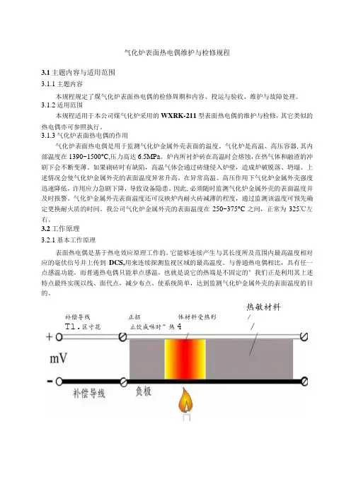
3.2工作原理3.2.1基本工作原理表面热电偶是基于热电效应原理工作的。
它能够连续产生与其长度所及范围内最高温度相对应的毫伏信号并上传到DCS,用来连续探测监视区域的最高温度。
与普通热电偶相比,具有任一点感温功能,而普通热电偶只能单点感温,也就是说它的热端是不固定的°我们正是利用其上述特点最终实现以线、面代点,减少布点、使系统简单,达到监测气化炉金属外壳的表面温度的目的。
热敏材料补偿导线正招体材料受热形/T1.区寸花止饮成咻时”热4 /图3.1 表面热电偶工作原理图图3.2表面热电偶外形图、表面热电偶布置图、缆式表面热电偶结构图3.2.2主耍技术指标令铠装材质:Incone1.600令分度号:K型令测温范围:80-880o C令外径:Φ3.0mm令响应时间:V5s令寿命:平均寿命20年令接头:防水接头令防护等级:IP67。

气化炉维护检修规程气化炉是工业生产中常用的一种燃烧设备,用于将固体或液态燃料转化为气体燃料,广泛应用于冶金、化工、能源等行业。
为了保证气化炉的正常运行和安全性,进行定期的维护检修是必不可少的。
下面是一个____字的气化炉维护检修规程,供参考:第一章总则第一条为确保气化炉的正常运行和安全性,提高设备的利用率和寿命,减少事故的发生,制定本规程。
第二条本规程适用于所有使用气化炉的生产工序。
第三条气化炉的维护检修应有维护人员专人负责,并按照本规程执行。
第四条维护检修人员应具备相关专业知识和技能,按照操作规程和安全规定进行工作。
第五条维护检修工作应严格按照生产计划和安全标准进行,并及时记录维护检修的内容和结果。
第二章维护检修内容第六条气化炉的维护检修包括预防性维护和故障维修。
第七条预防性维护主要包括日常巡视、定期检查和定期保养。
1. 日常巡视应包括炉体、炉门、烟道、进料口等的检查,发现问题及时处理。
2. 定期检查应包括炉体和炉内设备的检查,如炉壁的腐蚀、排渣装置的磨损等。
3. 定期保养应包括炉体清洗、燃烧器喷嘴更换、炉内设备的润滑等。
第八条故障维修主要是指气化炉发生故障时的紧急处理和维修。
1. 对于临时故障,应及时进行排除,如燃烧不稳定、温度过高等。
2. 对于较大的故障,应立即停机,并通知有关部门进行维修。
第九条在维护检修过程中,应注意设备的安全性和操作的规范性,严禁操作不当造成的事故发生。
第三章维护检修要求第十条维护检修人员应按照相应的操作规程进行工作,不得擅自更改或忽略任何操作步骤。
第十一条维护检修过程中应配备必要的工具和设备,并保持其良好的状态和数量。
第十二条维护检修人员在进行工作前,应检查设备压力、液位、温度等参数是否正常,如发现异常应及时报修。
第十三条维护检修过程中应严格遵守安全操作规程,如戴好安全帽、穿好防护服等。
第十四条维护检修完成后,应检查设备是否正常运行,如发现问题应及时进行排除。
第十五条维护检修人员在工作期间,应主动向上级报告工作内容和进展情况,并及时记录相关数据。
DELTONE气化炉表面热点探测预警系统安装维护说明书V1.0深圳市电利通科技有限公司目录第一章准备工作 (1)第二章技术培训 (1)第三章系统安装 (3)第四章系统调试 (16)第五章系统维护 (17)附表1 (19)附表2 (20)第一章准备工作1.1清点货物请按照合同(及我方的发货清单)对货物进行详细的核对,确定与合同上所注的产品数量相符,且无损坏。
1.2施工所需设备序号名称数量单位备注1 14mm开口扳手 1 把每人配备2 L型内六角扳手 1 套3 一字螺丝刀 1 支每人配备4 十字螺丝刀 1 支每人配备5 剪线钳 1 把每人配备6 剥线钳 1 把每人配备7 多用途工具刀 1 把每人配备8 卷尺 1 卷9 记号笔 1 支10 AC220V电源 1 路11 便携式电砂轮 1 台第二章技术培训2.1 简介气化炉表面热点探测预警系统是基于CT²C专利技术的对热点温度及环境温度进行监测的连续热电偶而构建的。
气化炉表面热点探测预警系统主要是探测气化炉表面的最高温度以避免潜在的危险而设计,但它的功能却不仅仅如此。
使用气化炉表面热点探测预警系统,车间操作人员可以得到实时温度信息并有效的调节内部过程;系统管理人员、工程师、维护和损失控制人员同样得到实时的测温区域中的温度信息来帮助程序及功能设计。
2.1.1 CT²C的独特性CT²C内部的两根“K” 型热电偶线由绝缘材料隔开而不直接接触。
绝缘材料的电阻特性使电缆拥有无限多的潜在的可产生毫伏信号的热电偶接点。
CT²C长度范围内的最高温度点就是热电偶接点,也是产生毫伏信号的接点。
2.1.2 CT²C的注册专利CT²C 享有以下专利保护:U.S. PATENTS 4491822, 4540972, 4614024 --CANADA 1194564 - -AUSTRALIA 555 243 - -RSA 82/7958 - -F.R. GERMANYP3279298.7-08 --EPO (AT-BE-CH-DE-FR-GB-IT-LI-LU-NL-SE INCL.) 0078675。
简介大型发电机组锅炉的空气预热器,在运行过程中为了防止着火燃烧,特配用本装置。
在现场经验表明,大多数空气预热器的起火,首先是在局部区域发生,由于沉积在预热器内部的受热元件上的未完全燃烧燃料着火引起的,这已为实验所证实。
实验室试验还证明,假如燃烧着的热点使受热元件温度上升到700℃以上时,这些热点可以导致钢制元件起火。
本装置是利用红外线信号来检测受热元件的内部温度。
当测得热点温度在150~200℃时,它就触发报警器报警,这样可以在达到金属着火温度之前有时间采取必要行动,使火警消灭在萌芽之中。
红外讯号的检测是通过一排四个特制的红外探头,用扫描方式对预热器进行全面检测,将测得的讯号送往电子线路进行处理。
为了保证本装置在长期运行中,有效的完成检测任务,有必要对于自身可靠性随时进行检测。
由于探头工作于预热器的下面,为了保证内部电子元件正常工作,用水进行冷却,使检测探头内部温度保证在50~55℃以下,如果温度升高或冷却水流不足时会报警提醒采取必要措施。
为了保证探头透镜表面清洁,特配备了一套风力自动除尘装置。
当镜头表面未能被清除干净,致使所测温度偏低时会报警提醒处理。
空气预热器红外热点探测系统本系统是采用红外线测温技术来检测空气预热器受热部件中热金属表面的温度。
温度检测是通过位于空气预热器风道入口截面上的一组四只红外探头扫描摆动来完成的,整个系统由机械传动机构和红外热点探测系统组成。
正常工作时,由机械传动机构带动装有探头的旋臂,缓慢地沿着180°左右的弧线作连续扫描摆动。
来自受热元件的红外线进入探头,并集中在内部的探测点上,由此所产生的电信号,经红外热点探测系统处理后,自动显示出空气预热器内部出现的“热点”的位置,及其他报警。
§1. 红外热点探测系统红外热点探测系统由红外测温传感器、信号处理器、可编程序控制器、继电-接触器和报警指示器等组成。
§1.1 红外探头当检测系统工作时,来自受热部件的红外线辐射到探头,经镜头聚焦到传感器内部的红外敏感器件上,由此所产生的信号,经前置放大器处理后作为信号处理器的输入信号。
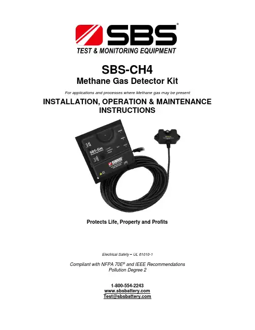
SBS-CH4Methane Gas Detector KitFor applications and processes where Methane gas may be present INSTALLATION, OPERATION & MAINTENANCEINSTRUCTIONSProtects Life, Property and ProfitsElectrical Safety – UL 61010-1Compliant with NFPA 70E® and IEEE RecommendationsPollution Degree 21-800-554-2243*******************Warnings∙This detector is added protection, not a substitute for prudent safety measures, for where methane gas may be present.∙For large or highly-sensitive areas, SBS recommends installing additional sensors for increased coverage area.∙The methane sensor does not provide protection from fires or methane explosions.The relay contacts are intended to be connected to a safety system that would enable audible alarms, system shutdown and ventilation.∙Ensure that installation complies completely with all relevant Local, State, Federal and OSHA safety and health regulations.∙If a sensor enters warning or alarm mode there is a risk of combustion or explosion. To avoid injury, leave the area immediately.∙The sensor is calibrated for operation in air. Tampering with the sensor or operation in environments that are exposed to other types of gases can lead to inaccuratereadings, false alarms or permanent damage.∙Please see troubleshooting guide for list of gases and compounds that may damage or alter a sensor’s performance.∙Uncured silicone compounds or extended exposure to silicone off gassing can give inaccurate readings or false alarms on a sensor.Table of ContentsDescription Page SectionBenefits 5 2.0Specifications 6 4.0Main Control 7 6.0Operation 12 8.0Testing the Sensor 13 10.0Main Unit and Accessories Part No. DescriptionSBS-CH4Methane Gas DetectorIncludes: one (1) main control, one (1) CH4-SENSOR and one (1) 25 ft. cableCH4-JB Junction Box with Knockouts, 4 11/16" X 4 11/16", MetalCH4-SENSOR Methane Gas Sensor Only (No Cable)CH4-SENSOR-25FT Additional/Replacement Methane Gas Sensor with 25 ft. Cable CH4-SENSOR-50FT Additional/Replacement Methane Gas Sensor with 50 ft. Cable CH4-SENSOR-100FT Additional/Replacement Methane Gas Sensor with 100 ft. CableCH4-TESTKIT Field Test Kit for SBS-CH4Includes: case, regulator, tubing and two (2) cylinders of CH4 gas (25%LEL and 50%LEL)CH4-TESTKIT-INTL Field Test Kit for SBS-CH4Includes: case, regulator and tubing – does not include CH4 gas cylindersE190399110Vac 3 Prong AC Cord, 10 Ft., 18-3 AWG1.0 OverviewAt room temperature and pressure, methane is a colorless, odorless gas.Concentrations of 4.4% to 17% CH4 mixed with air can be explosive. Sparks or hot surfaces can ignite methane gas.The SBS-CH4 methane detector acts as a monitor and provides a visual and audible alarm when methane gas is detected. The unit also has a 25%LEL concentration relay that can trigger exhaust fan operation and a 50%LEL concentration relay that can trigger a building management/alarm system (via SCADA/Modbus) before the gas reaches the lower explosive limit (LEL) of 4.4%.2.0 BenefitsIn addition to protecting employees and property, the detector may also reduce the following costs: Energy EfficienciesInstead of continuously running an exhaust fan to prevent methane gas accumulation, use the detector to activate a fan only if the gas concentration reaches 25%LEL.Insurance SavingsInstallation of a detector in areas where batteries are charged may result in a premium reduction.3.0 How it WorksShould the concentration of methane gas in the air surrounding the sensor reach 25%LEL by volume, the “25%LEL Warning” yellow LED will light up on the main control of the unit. In addition, the25%LEL internal relay will energize and can be used to activate a remote exhaust fan.Should the methane gas concentration reach 50%LEL by volume, the “50%LEL Alarm” red LED will light up, the strobe will flash and an audible alarm will sound. In addition, the 50%LEL internal relay will energize and can be used to activate a building management/alarm system (via SCADA/Modbus). The SBS-CH4 provides automatic operation, continuous detection, high sensitivity, stability and solid-state reliability. The unit uses 120/240 Vac 50/60 Hz and/or 12 - 48 Vdc operating voltages.4.0 SpecificationsDimensions∙Main control: 4.7" L x 4.7" W x 1.2" D∙Sensor: 3.1" L x 1.6" W x 0.87" DMounting∙Wall: two 3/16" screws (not included)∙CH4-JB Junction box: 4 11/16" x 4 11/16" 2-gang junction boxPower Requirements/OptionsWarning: Power requirements for the unit and relays should not exceed min/max specifications ∙120 Vac, 50/60 Hz Nominal (Terminal J8)o93 - 121 Vaco250mA / 10W Max∙220 Vac, 50/60 Hz Nominal (Terminal J8)o185 - 242 Vaco125mA / 10W Max∙12-48 Vdc Nominal (Terminal J9)o9 - 58 Vdco600mA / 6W Maxo Note: An earth ground must be supplied to the GND terminal on the AC terminal block when using only the DC power supplyRelays∙25%LEL Warning Relay (Terminal J6)o 1 Normally Open and 1 Normally Closed contacto Rated for 15 A resistive @ 120 Vaco Rated for 10 A resistive @ 277 Vaco Rated for 10 A resistive @ 28 Vdc∙50%LEL Alarm Relay (Terminal J3)o 1 Normally Open and 1 Normally Closed contacto Rated for 0.5A @ 28 VdcTemperature/Humidity∙Operating Temperature Range: 32°F (0°C) to 122°F (50°C)∙Operating Humidity Range: 20-95% non-condensing∙Storage Humidity Range: 5-95% non-condensingMaximum Altitude∙2000 metersAudible Alarm∙85 dB at 10’ @ 1.6 - 3.2 KHzStrobe LED∙*******************.2V5.0 SensorThe CH4-SENSOR consists of an electronic sensing element whose electrical conductivity increases when Methane is detected at its surface. Conductivity of the sensor is proportional to the gas concentration, which is continuously monitored by the electronic alarm circuits.The sensor is calibrated specifically for methane gas (CH 4) and can detect other combustible gases that it is not specifically calibrated for.6.0 Main ControlSensor HeadStrobe AlarmIndividual Sensor Indicators (For troubleshooting, refer to page 14.)Methane SensorCat5 Cable(25 ft. std., 50/100 ft. optional)Main ControlMain Control Indicators (3 LEDs)7.0 InstallationWARNINGAC voltage relay terminals (120/240 Vac) are located within this detector, presenting a hazard toservice technicians. Only qualified technicians should open the detector case and service the internal circuits. Ensure power is removed from the detector relays prior to servicing the unit. Failure to do so may result in injury or death.Mounting and Power OptionsAlarm WiringCH4-JB Junction Box Mountable (optional) Mounts to a standard, 4 11/16" x 4 11/16" 2-gang junction boxHardwire OptionRun AC and/or DC power and alarm wires through back of the unit, into the gang box and out through conduit.E190399 AC Line Cord3-prong grounded AC cord, 18-3 AWGWall MountableIntegrated back mounting plate allows user to easily mount directly to any wall using 3/16" screws (not included).WiringPower and alarm wires can run through the sides of the unit.Input PowerMounting LocationMethane is colorless and odorless; the leaks from a refrigerated liquid container are heavier than air due to increased density of the cold gas, however the gas at ambient temperature is lighter than air and thus rises. The sensor should be installed in proper location for detection of leaking liquid gas, or rising ambient temperature gas accumulation.The detector measures methane gas concentration in the air immediately surrounding the sensor’s surface. The area one sensor will monitor depends on the properties of the compartment or room. Methane gas may accumulate in several areas of the compartment or room and multiplesensors/detectors may be necessary depending upon construction and design of the application.The main control can be mounted wherever is convenient for the user, but should be within the cable length range to connect to each sensor.The sensor should be mounted at the location where leak detection or gas concentration buildup is to be monitored. Each sensor connects with the main control via the cable.Carefully remove the main control cover by removing the two screws located on the front of the cover. Attach the main control to the wall, ceiling or optional junction box using the mounting holes at the top and bottom of the main control’s mounting plate.After the power and relay wiring is complete, connect each cable from main control to each sensor and refasten the main control cover.Power OptionsThe detector has terminal blocks for connections to a single-phase 120/240 Vac 50/60 Hz power source (Terminal J8), and/or a 12-48 Vdc power source (Terminal J9). The power supply inputs are redundant, so the unit can use the DC input as a backup source.RelaysThe detector has two (2) internal alarm relays:∙25%LEL warning relay (Terminal J6) is activated when a sensor detects 25%LEL concentration of methane gas. The 25%LEL relay’s dry contacts are rated at 10A/250 Vac,sufficient for most 1/3 HP exhaust fans.∙50%LEL alarm relay (Terminal J3) is activated when a sensor detects 50%LEL concentration of methane gas. The 50%LEL relay’s dry contacts are rated for 0.5A/28 Vdc.∙Note: For higher current requirements, add an external relay.Mounting OptionsJunction Box MountedFor 120/240 Vac power, use 18-3 gauge stranded wire.For 9 - 58 Vdc power, use 18-2 conductor insulated wire.For relay wires, use stranded wire. Maximum wire size for connector terminations is 14 AWG. Stranded conductors must be terminated in a manner to prevent shorting from one terminal to another by a loose strand. Tin the wires with solder if required.Wall MountedFor 120 Vac power, an 18-3 gauge insulated line cord is required.For 9 - 58 Vdc power, use 18-2 conductor insulated cable from the DC supply.For relay wires, use stranded wire. Maximum wire size for connector terminations is 14 AWG.Disconnection of Supplying PowerWhen the unit is hard wired, an external 10 Amp (minimum) circuit-breaker or switch should be installed to act as a disconnecting device. The circuit-breaker must open all supply conductors simultaneously, be easily reached by operators and be marked as the disconnecting device for the equipment.For Installation of Additional SensorsA maximum of three (3) sensors may be connected to each main control. Multiple detectors and sensors can be installed to meet the space coverage requirements of your particular installation.Locate the additional sensors ’ installation points within cable reach of the main control and mount the sensor. Connect the cables from any additional sensors to the Sensor 2 and Sensor 3 inputs on the main control.SBS supplies a tie-wrap to secure the AC mains ’ wiring. The tie wrap can rotate up to 270 degrees to accommodate your installation.Alarm System ElectronicsPlease refer to the illustration below to identify proper power and relay connection points in the detector. It is advisable to use a pair of 14 gauge or smaller stranded wire for the relay contacts to help reduce any interference within the area that may cause false alarms.Each of the Cat5 sensor input connections has a status indicator LED on the main control, which will illuminate solid green when a sensor is connected and operating normally. A sensor’s corresponding LED will flash at the same rate as the strobe LED when detecting 25%LEL or 50%LEL CH4 concentration. The LED for a sensor that is in alarm mode will flash at the same rate as the strobe LED. The alarming sensor and strobe LED will flash at a faster rate than the LED for a sensor that is only in warning mode.Terminal Connection DiagramUsing the Mechanical Relays1. Remove the front cover of the main control by removing two fix screws and pulling straight offthe body. This will reveal the inner electronics of the alarm box.2. Locate the terminal blocks for the relays and determine which condition you would like therelay to be related to. Use the 25%LEL relay (Terminal J6) for the warning condition and the 50%LEL relay (Terminal J3) for the alarm condition.3. Replace the front cover on the alarm box.8.0 OperationKeep the detector on at all times. The solid green LED for ‘POWER’ on the main control indicates that the detector is powered on.When power is first turned on, a warm up period of 30 seconds will elapse before the unit will function. This delay is to prevent false activation of the internal relays and alarm.Should the concentration of methane gas in the air surrounding the sensor reach 25%LEL by volume, the “25%LEL Warning” yellow LED will light up on the main control of the unit. In addition, the25%LEL internal relay will energize and can be used to activate a remote exhaust fan.Should the methane gas concentration reach 50%LEL by volume, the “50%LEL Alarm” red LED will light up, the strobe will flash and an audible alarm will sound. In addition, the 50%LEL internal relay will energize and can be used to activate a building management/alarm system (via SCADA/Modbus).ConditionMain ControlIndicatorsPower Warning AlarmIndividual SensorIndicatorsRelayClosureAudibleAlarmStrobeNormal Operation(sensor installed)None None NoneCH4 Warning(25%LEL CH4)(blinking green)WarningRelayEnergizedNone NoneCH4 Alarm(50%LEL CH4)(same flash rate as strobe)Warning andAlarm RelayEnergizedON ONSensor/Cable Fault None None NoneCommunicationwith Sensor Lost(plugged in, but not lit)None None NoneMain Control IndicatorsIndividual Sensor Indicators9.0 Electrical TestingA "TEST" button is located on the front of the main control. Push and hold this button for approximately 10 seconds to test the unit's electronic circuitry.The warning and alarm LEDs will light up in sequence, the strobe will flash, the relays will activate whatever is connected to them and the internal warning alarm will sound.Note: The "TEST" button does NOT test the sensor(s) itself –only the unit’s electronic circuitry.10.0 Testing the SensorThe sensors and main controls are factory calibrated. It is recommended to test each sensor’s functionality every 12-18 months with the CH4-TESTKIT.The CH4-TESTKIT is intended for periodic testing of the functionality and proper operation of the system. Once a sensor is installed, calibration or adjustment of the sensor is not possible. Please contact your sales representative if sensor calibration is desired or required.The CH4-TESTKIT includes the following:∙25%LEL (17 liters) CH4 in air calibrated gas canister∙50%LEL (17 liters) CH4 in air calibrated gas canister∙Regulator∙Flexible tubing with sensor head adapterTesting the 25%LEL Warning and 50%LEL Alarm State1. Connect the test fixture to the 25%LEL CH4 air gas cylinder.2. Secure the test fixture to the sensor module connected to sensor by pressing the flexible tubingcompletely over the inlet to the sensor head.3. Turn on the gas flow by slowly cracking then fully opening the valve completely. Please wait 60seconds to ensure the air in the tubing has been purged.4. Continue gas flow and wait for the yellow LED warning to light up and the 25%LEL relay toenergize.5. Turn off gas and remove from sensor.6. Repeat Steps 1-5 above using the 50%LEL CH4 air gas cylinder to activate the 50%LEL alarmand relay. The 50%LEL alarm threshold is connected to the red LED, the audible alarm and the strobe light up, which will activate during testing.7. Repeat steps for every sensor installed.Note: If the unit does not alarm during these tests the sensor may need to be replaced.Replacing the SensorIn a typical operating environment SBS recommends that each sensor be replaced every three years. An abusive operating environment can and will shorten a unit’s useful life. In dusty/dirty applicationsor in situations where a sensor is often subjected to different gases, it is recommended to replace each sensor after one (1) year.11.0 Troubleshooting and MaintenanceNo PowerVerify the AC and/or DC power cables are installed per the connection diagram on page 11.RelaysThe SBS-CH4 system was designed for the relays to operate in a failsafe condition when the power supply is interrupted. If the fan connected to a relay runs as soon as the unit is powered on, the unit has been wired for the use of the Normally Open contact instead of a Normally Closed contact.False AlarmsEach sensor has been calibrated for the detection of methane gas, however any combustible gas that comes in contact with a sensor has the potential to activate the warning and/or alarm relays. Contact with any individual or combination of the following gases could trigger false alarms and/or contaminate a sensor.Gases include but are not limited to:-Acetone-Acetylene-Ammonia-Benzene-Butane-n-Butyl Acetate -Carbon Dioxide -Carbon Monoxide -Ethane-Ethanol-Ethyl Acetate -Ethyl Ether-Ethyl Oxide-Gasoline-Heptane-Hexane-Isopropyl Alcohol-Methane-Methane Cyanide-Methane Sulfide-Methanol-Methyl Ethyl Ketone-Nitric Oxide-Nitric Dioxide-Propane-Propylene Oxide-Styrene-Sulfur Dioxide-Toluene-Turpentine-Vinyl Acetate-XyleneIf a sensor’s warning or alarm condition is reached, ventilate the area with clean air. This should reduce the concentration of most gases and the warning or alarm condition should clear.Note - when a warning occurs at 25%LEL, the warning will not clear until concentrations drop below 0.5%. Similarly, when an alarm occurs at 50%LEL, the alarm will not clear until concentrations drop below 1.5%.Avoid installation in highly corrosive environments where high densities of Methane sulfide, sulfur oxide, chlorine, Methane chloride, etc. may be present. These gases can cause corrosion of the element and the power leads to the circuit board.A sensor’s output characteristics can be affected if the sensor becomes contaminated or exposed to heavy alkaline metals.A sensor cannot operate in a zero or low oxygen content atmosphere.If a sensor collects water condensation, its characteristics may temporarily drift. However, light levels of condensation under normal indoor use should not pose a significant problem with performance.StorageThe longer a sensor is stored prior to being energized, the longer the warm up and stabilization period may become. Storage Humidity Range: 5 - 95% non-condensing.Maintenance TipsTo maintain the unit, it is recommended to:1. Test the detector once a month by pressing the ‘TEST’ button.2. Vacuum the alarm cover once a month to remove accumulated dust.3. Never use detergents or solvents to clean the unit or sensor. Chemicals can permanentlydamage or temporarily contaminate a sensor.4. Avoid spraying air fresheners, hair spray, paint or other aerosols near a sensor.5. Never paint the unit or sensor. Paint will seal the vents and interfere with proper sensoroperation.WARNINGSDo not disassemble unit or attempt to repair or modify any component of this instrument. This instrument contains no user serviceable parts, and substitution of components may impair intrinsic safety, which may adversely affect product performance and result in injuryThe SBS-CH4 Methane Alarm System is not a standalone safety device and does not provide protection from methane explosions. The relay contacts are intended to be connected to a safety system, enabling audible alarms, system shutdown, ventilation, or other measures to ensure monitoring of methane gas occurs before concentrations reach dangerous levels.The information in this sheet has been carefully reviewed and is believed to be accurate; however, no responsibility is assumed for inaccuracies. Storage Battery Systems, LLC reserves the right to make changes without further notice to any product, datasheet, technical data bulletin, or website.Storage Battery Systems, LLC makes no warranty, representation of guarantee regarding the suitability of its product for any particular purpose, nor does Storage Battery Systems, LLC assume any liability arising out of the application or use of any product and specifically disclaims any and all liability, including without limitation consequential or incidental damages. “Typical” parameters can and do v ary in different applications. All operating parameters, including “Typical” must be validated for each customer application by customer’s technical experts.Storage Battery Systems, LLC products are not designed, intended, or authorized for use in any application in which the failure of the SBS product could create a situation where personal injury or death may occur.Should buyer purchase or use SBS products for any such unintended or unauthorized application, Buyer shall indemnify and hold Storage Battery Systems, LLC and its officers, employees, subsidiaries, affiliates, and distributors harmless against all claims, costs, damages, and expenses, and reasonable attorney fees arising out of, directly or indirectly, any claim of personal injury or death associated with such unintended or unauthorized use, even if claim alleges that Storage Battery Systems, LLC was negligent regarding the design or manufacture of the part.In the case of a defect in the sensor, Storage Battery Systems, LLC shall not be liable for any damages which may result, including, but not limited to, loss of revenue, property, or life. In an event, Storage Battery Systems, LLC shall limit liability to replacement of the defective unit. Storage Battery Systems, LLC does not convey any license under its patent rights nor the rights of others.。
热点探测器在气化炉表面测温中的配置及安装以煤和氧气为原料气化反应的气化炉为压力容器,炉内正常温度在1300℃左右,甚至高达1500℃以上。
炉内所衬炉砖在高温时会熔蚀,受热气体和熔渣的冲刷,耐火砖不断变薄。
在某些情况下,例如砌砖时的缺陷,炉砖会掉下,或炽热气体通过砖缝侵入。
炉内耐火砖的减薄甚至脱落或炽热气体通过砖缝侵入会使气化炉炉壁表面温度升高,使受压的气化炉金属外壳强度降低,许用应力迅速下降,造成设备不安全,进而导致安全事故发生。
因此要求实时测量气化炉表面温度并给予报警。
测量气化炉表面温度的另一个目的是,炉表面温度反映了炉内耐火砖减薄的程度,可预先确定更换耐火砖的时间。
气化炉表面测温系统是将测温元件敷设在气化炉容器壳上来进行工作的,测温元件是一种能够探测一条连续路线上存在的最高温度的线型热点探测器,能够连续产生与其敷设区域内的最高温度相对应的毫伏信号,将此信号转换、传送到DCS,以监控最高温度出现的位置。
昌晖仪表生产的热点探测器与普通热电偶不同之处在于它的热接点不固定,而是始终与线缆上的最高温度相对应。
如果把热点探测器合理地敷设在一个面上,测温电缆反映出的温度可视为其所达面上存在的最高温度。
热点探测器工作原理热点探测器的基本工作原理为热电效应原理。
热电效应是德国科学家Seebeck(塞贝克)在1821年发现的:将两种不同材质的导体A和导体B,首尾焊接起来,构成一个闭合回路,这两个焊接点称之为参比点和热接点。
当参比点与热接点之间存在温差时,这个闭合回路就会产生一个热电势。
热电势的大小只与参比点和热接点的温度有关;这种现象就是热电效应。
普通热电偶就是利用此原理工作。
热点探测器内部填充了NTC热敏材料-一种负温度系数很大的半导体热敏材料。
这种材料在常温时呈高阻,受热时呈低阻。
当热点探测器上任何一点(T1)的温度高于其它部分的温度时,该处的热电偶导线之间的绝缘电阻(R)降低,从而出现“临时”热接点,相当于点式热电偶的金属热接点,作用与普通热电偶的热接点相同,如图1所示。
气化炉维护检修规程1 总则1。
1适用范围本规程适用于山东华鲁恒升化工股份有限公司A气化炉及B/C气化炉的维护检修。
1.2设备概述气化炉为华鲁恒升大氮肥国产化装置中核心设备之一,用于水煤浆的加压气化,为合成氨或甲醇生产提供粗原料气。
我公司采用的气化炉分为两种类型:一种为西北化工研究院的专有技术(B/C气化炉,类似于德士古气化炉);另一种为华东理工大学的专有技术(A气化炉,为四烧嘴对撞式,具有自主知识产权)。
1.3设备结构与技术性能简介1.3。
1 设备结构A气化炉和B/C气化炉均由燃烧室和激冷室组成。
燃烧室内衬耐火材料,就燃烧室筒体来说,从内到外依次为热面砖、背衬砖、隔热砖和可压缩层(膨胀材料)。
衬里材料结构为:炉膛基本为竖向直筒;上面为球形拱顶;下面为收缩的渣口结构,即锥底。
在使用中蚀损最严重的部位是向火面砖。
A气化炉和B/C气化炉在结构上的主要区别有:a)A气化炉安四个烧嘴,在炉子侧面即燃烧室筒体上水平对置安装,A气化炉开车时在炉子顶部安装预热烧嘴,正常生产时炉子顶部用堵头堵死;B/C气化炉只一个烧嘴,在炉子顶部朝下安装,开车时预热烧嘴也安装在此。
b)A气化炉在激冷室只有下降管没有上升管,而设置了气泡分离器;B/C气化炉既有下降管也有上升管,没有设置气泡分离器。
1。
3。
2 技术参数与性能A气化炉和B/C气化炉的介质均为O2、H2、CO、CO2、H2O、H2S、N2和炉渣,工作压力均为6.5MPa,燃烧室工作温度均为1450℃,激冷室工作温度均为252℃.单炉日处理煤量A气化炉比B/C气化炉略高。
另外,A气化炉产生的气化气中有效气体成分(CO+ H2)含量高。
1.4设备完好标准1.4。
1 零部件a)各零部件和附件完整、齐全,质量符合要求b)仪表、仪器、安全联锁装置准确、灵敏,不超期使用1.4.2 设备性能a)气化气产量、纯度达到设计要求b)各项工艺参数符合操作指标1.4.4 技术资料1.4.4.1技术资料准确齐全,至少包括:c)竣工图,制造、安装技术文件(含无损检测记录、设备制造合格证、压力容器制造质量证明书、安装工程交工技术文件),设备调试记录,使用说明书d)设备结构及易损件图纸e)设备运行累计时间f)设备检修方案,实际修理情况记录及技术鉴定记录g)设备技术改造的方案、图样、材料质量证明书、施工质量检验技术文件和资料h)安全附件校验、修理和更换记录i)历年设备缺陷、事故情况记录及处理报告1。
气化炉表面温度采集系统维护与检修规程30.1主题内容与适用范围30.1.1主题内容本规程规定了煤气化炉表面温度采集系统的检修周期和内容、投运与验收、维护与故障处理。
30.1.2适用范围本规程仅适用于本公司煤气化炉表面温度采集系统的维护与检修。
30. 1.3气化炉表面温度采集系统的作用该系统的作用是将表面热电偶测得的温度信号通过补偿导线与安装在现场接线箱内的I/O设备相连,再经I/O设备以通讯的方式传输到DCS或上位机。
30.2工作原理30.3.1基本工作原理表面热电偶测得的温度信号通过补偿导线与安装在现场接线箱内的I/O设备接口点对点地连接,信号进入系统后即被I/O模块转换为数字信号,再经过系统内部总线传送到网关,然后由网关将信号传送到上一层的开放总线,最后经开放总线到达控制系统(DCS)o30.2.2气化炉表面温度采集系统的结构特点信号的采集与传输采用德国PePPerI+Fuchs公司远程I/O系统。
该系统支持MODBUS、PROFIBUS>FF等通讯协议,可与目前流彳亍的HONEYWE11、SIEMENS、DE1TAV>ABB、FOXBORO>YOKoGAWA、ROKWE11、MODICON绝大多数DCS/P1C对接。
30.2.3系统配置I/O模块:6台,每个模块4通道表面热电偶输入,尚有2个通道备用。
配相应数量的端子附件。
通讯模块(网送):2台,冗余设计。
电源模块:2台,冗余设计。
现场防瞬线箱:不锈钢材质,属于隔爆型,尺寸:800×8∞×350mm,防护等级:IP66。
30.3主要技术指标1)1/0模块:FB5205B型①所有I/O模块都是可热插拔式设计,低功耗,低发热量,安全隔离功能,1ED状态显示,长寿命。
②单个I/O模块宽度只有16mm,可以紧凑型安装,无需担心散热问题。
③块采用最新的安装固定技术,使得模块可直接固定在I/O插槽内,无需安装螺丝。
气化炉维护检修规程模版第一章总则第一条: 为了保证气化炉的正常运行,延长设备寿命,确保安全生产,制定本规程。
第二条: 本规程适用于所有使用气化炉的相关人员。
第三条: 气化炉的维护检修工作由专业维护人员负责,必须经过培训并持证上岗。
第四条: 维护检修工作必须定期进行,确保设备长时间稳定、高效工作。
第五条: 任何人不得擅自拆卸、改装或修改气化炉设备。
第六条: 本规程中未尽事宜,按照相关法律法规进行。
第二章维护检修职责第七条: 维护人员必须认真履行以下职责:1.定期检查气化炉设备的电气安全,包括电缆、接线、开关等的检查测试。
2.定期检查气化炉设备的机械部分,包括管道、泵、阀门等的检查清理。
3.定期检查气化炉设备的燃烧情况,包括火焰状态、温度等的检查测试。
4.定期检查气化炉设备的水平补给系统,包括水泵、水箱等的检查清理。
5.及时处理气化炉设备出现的故障,并记录以备查阅。
第八条: 维护人员必须保证操作规范,遵守安全操作手册,防止人为错误引发事故。
第三章维护检修操作第九条: 维护人员在操作气化炉维修时,必须戴上劳动防护用品,如安全眼镜、手套、防护服等。
第十条: 气化炉维修前,必须切断电源,确保安全操作。
第十一条: 维护人员必须按照操作规程进行维修,不得擅自改动设备及其配件。
第十二条: 维护检修过程中,如需要更换设备配件,必须使用正规厂家的配件,确保质量。
第十三条: 维护检修完毕后,必须清理周围环境,归位存放工具和设备。
第十四条: 维护人员必须及时填写维修记录,并向主管报告维修情况。
第四章维护检修管理第十五条: 维护人员必须定期参加培训,了解最新的维护技术和设备更新情况。
第十六条: 维护人员必须遵守工作纪律,服从指挥,不得私自调休或请假。
第十七条: 维护人员必须定期参加身体健康检查,确保工作状态。
第十八条: 维护人员必须爱护工作设备,保持设备清洁、整齐。
第十九条: 维护人员必须遵守操作规程,不得违章操作或私自开启设备。
气化炉高温热电偶安全操作及保养规程气化炉是一种常用于冶炼和加工金属的设备,其中热电偶是常用的温度测量器。
在气化炉的运行过程中,正确使用和保养高温热电偶是非常重要的,不仅关系到生产效率和品质,还涉及到安全问题。
本文将介绍气化炉高温热电偶的安全操作和保养规程。
一、热电偶安全操作规程1.1 选择适当的热电偶在选择热电偶时,应根据气化炉的工作条件和要求选择适当的热电偶型号和材料。
一般情况下,使用温度范围较高、热响应时间较短、抗氧化、抗高温腐蚀性能好的热电偶。
1.2 安装热电偶热电偶的安装应由专业人员操作,应尽量避免弯折和扭曲,防止热电偶在使用过程中受力过大而造成永久性弯曲。
在安装过程中,应注意热电偶的接头,一定要确保接触良好。
若出现连接不好的情况,应及时更换。
同时,还要将热电偶与控制仪器进行正确接线,以保证温度信号的准确传递。
1.3 正确使用热电偶使用热电偶时,应注意以下事项:1.不要使用过程中折弯、弯曲热电偶,以免影响温度测量的准确性;2.不要将热电偶头摔坏或挤碎,以免改变其热响应特性和测量精度;3.不要让热电偶长期暴露在高温、高湿环境中,以免影响其使用寿命;4.不要将热电偶接触金属物体,以免引起误差。
1.4 周期性检测热电偶为了保证热电偶的测量精度和准确性,应定期对热电偶进行检测,以发现并解决问题。
检测时间间隔应根据气化炉的工作情况和要求酌情调整。
二、热电偶保养规程2.1 清洗热电偶在使用热电偶的过程中,表面会形成一层氧化物和杂质,这直接影响到热电偶的温度测量准确性。
因此,必须对热电偶进行周期性的清洗。
清洗时,应使用无水酒精或去离子水浸泡约5~10分钟,再用软毛刷轻轻擦拭,以去除表面的污垢。
2.2 维护热电偶连接器定期检查和保养热电偶与控制仪器之间的连接器,限制其使用寿命,增加其稳定性和运行的安全性。
2.3 储存热电偶在存储热电偶时,应注意以下事项:1.应将热电偶放置在干燥、阴凉和通风良好的地方,以避免其暴露在阳光下、高温或高湿度环境中;2.保持热电偶清洁干燥,以防止其表面结露导电,引起测量误差或热电偶短路;3.不要将热电偶与其他金属物体接触,以避免出现腐蚀、损坏等情况。
热解析仪维护操作说明书一、概述:热解析仪是用于分析和检测各种材料中有机物的仪器。
为了保证仪器的正常运行和延长其使用寿命,以下是热解析仪的维护操作说明。
二、日常维护:1. 清洁外部表面:定期使用柔软的布或棉纱蘸取少量酒精擦拭仪器外部表面,以保持其清洁。
2. 定期校准:根据使用手册中的指导,定期进行仪器校准,以确保数据的准确性。
3. 确保通风良好:在使用热解析仪时,确保周围环境通风良好,以防止仪器发生过热。
4. 清理气体管道:定期检查和清理热解析仪中的气体管道,以防止气流受阻。
5. 仪器存放:当不使用热解析仪时,应将其存放在干燥、无腐蚀性气体的环境中,并保持离尘源远离。
三、故障排除:1. 电源问题:若热解析仪无法启动,请检查电源线是否连接稳固,并确保电源插座正常工作。
2. 数据显示问题:如果在仪器运行时数据显示不正常,请首先检查连接电缆是否松动,确保信号传输正常。
3. 气体泄漏问题:如发现气体泄漏,请立即关闭气源,并检查气体管道连接处是否松动、损坏或老化。
4. 温度异常:如果仪器温度异常,请检查加热元件是否正常工作,及时更换损坏的零件。
四、保养和更换零件:1. 定期更换滤芯:根据仪器说明书,定期更换热解析仪中的滤芯,以确保气体流动的纯净性。
2. 清洁和替换样品舱:定期将样品舱内的残留物清理干净,并根据需要更换样品舱的密封垫。
3. 定期校准加热元件:根据使用手册指导,定期校准热解析仪中的加热元件,以确保温度控制的准确性。
五、安全注意事项:1. 避免使用过程中的触电:确保手部干燥,不要触摸仪器内部或打开仪器盖子。
2. 避免过度加热:使用过程中避免过度加热,以防止仪器损坏或发生事故。
3. 警惕气体泄漏:使用过程中注意气体泄漏情况,尽量保持仪器密封。
4. 注意存放环境:将仪器存放在干燥、温度适宜、远离腐蚀性物质的环境中。
综上所述,通过正确的维护操作可以保证热解析仪的正常运行和使用寿命。
用户在日常使用中,应该定期进行维护和检查,遵守操作规程,并时刻注意安全事项,以确保仪器的稳定性和准确性。