《汽车专业英语读译教程》--19-U11TA
- 格式:ppt
- 大小:695.50 KB
- 文档页数:24
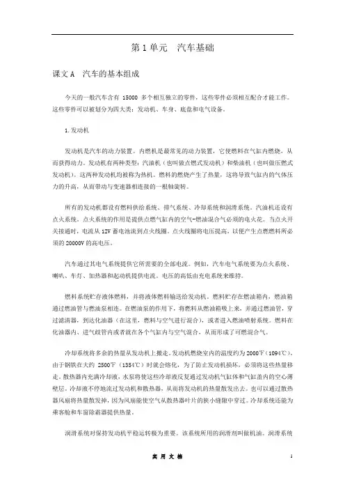
第1单元汽车基础课文A 汽车的基本组成今天的一般汽车含有15000多个相互独立的零件,这些零件必须相互配合才能工作。
这些零件可以被划分为四大类:发动机、车身、底盘和电气设备。
1.发动机发动机是汽车的动力装置。
内燃机是最常见的动力装置,它使燃料在气缸内燃烧,从而获得动力。
发动机有两种类型:汽油机(也叫做点燃式发动机)和柴油机(也叫做压燃式发动机)。
这两种发动机均被称为热机。
燃料的燃烧产生了热量,这将导致气缸内的气体压力的升高,从而带动与变速器相连接的一根轴旋转。
所有的发动机都设有燃料供给系统、排气系统、冷却系统和润滑系统。
汽油机还设有点火系统。
点火系统的作用是提供点燃气缸内的空气-燃油混合气必须的电火花。
当点火开关接通时,电流从12V蓄电池流到点火线圈。
点火线圈将电压提高,以便产生点燃燃料所必须的20000V的高电压。
汽车通过其电气系统提供它所需要的全部电流。
例如,汽车电气系统要为点火系统、喇叭、车灯、加热器和起动机提供电流。
电压的高低由充电系统来维持。
燃料系统贮存液体燃料,并将液体燃料输送给发动机。
燃料贮存在燃油箱内,燃油箱通过燃油管与燃油泵相连。
在燃油泵的作用下,将燃料从燃油箱吸上来,并通过燃油管,穿过滤清器,到达化油器(在这里,燃料与空气进行混合),或者进入燃油喷射系统。
燃料在化油器内、进气歧管内或者就在各个气缸内与空气混合,从而形成了可燃混合气。
冷却系统将多余的热量从发动机上搬走。
发动机燃烧室内的温度约为2000℉(1094℃)。
由于钢铁在大约2500℉(1354℃)时就会熔化,为了防止发动机损坏,必须将这些热量移走。
散热器内充满冷却液,水泵将使这些冷却液反复通过发动机气缸体和气缸盖内的空心薄壁层。
冷却液不停地流过发动机和散热器,从而将发动机的热量散发出去。
也可以通过散热器风扇将热量散发掉,因为风扇能使空气从散热器叶片的狭小缝隙中穿过。
冷却系统还能为乘客舱和车窗除霜器提供热量。
润滑系统对保持发动机平稳运转极为重要。


Brushless DC Motor SystemsIn recent years the number of drive systems available to designers has increased considerably. The advent and increasing use of stepper motors, inverter-fed ac machines,switched reluctance motors and brushless machines have all addressed particular applications and in some cases these application areas overlap. The correct choice of a drive system for a particular application depends not only upon the speed and torque requirements but also on performance, response, complexity and cost constraints.The brushless DC motor (BDCM) system is emerging as one of the most useful drive options for a wide range of applications ranging from small, low power fans and disc drives, through medium size domestic appliance motors and up to larger industrial and aviational robotic and servo drives.This section will review the theory and operation of brushless DC motors and describe some of the considerations to be made when designing BDCM drive systems using PowerMOS devices as the main inverter switches.BackgroundThe principal advantage of a conventional DC machinecompared to an AC machine is the ease with which a DC motor can be controlled to give variable speed operation, including direction reversal and regenerative braking capability. The main disadvantage of a DC machine is that the carbon brushes of a DC motor generate dust and also require maintenance and eventual replacement. The RFI generated by the brushgear of a DC motor can be quite large and, in certain environments, the sparks themselves can be unwelcome or hazardous. The brushless DC motor was developed to achieve the performance of a conventionalDC machine without the problems associated with its brushes. The principal advantages of the BDCM system are:• Long life and high reliability• High efficiency• Operation at high speeds and over a wide speed range • Peak torque capability from standstill up to high speeds • Simple rugged rotor construction•Operation in vacuum or in explosive or hazardous environments• Elimination of RFI due to brush commutationDC motor configurationsIn a conventional DC motor the field energy is provided byeither a permanent magnet or a field winding. Both of these arrangements involve quite large, bulky arrangements for the field. In the case of wound field DC motors this is due to large number of turns needed to generate the required electromagnetic field in the airgap of the machine. In the case of permanent magnet DC machines the low energy density of traditional permanent magnet materials means that large magnets are required in order to give reasonable airgap fluxes and avoid demagnetisation. If either of these two options are used with the field excitation on the rotor of the machine then the inertia and weight of the rotor make the machine impractical in terms of its size and dynamic Response.AconventionalDCmachine has alarge number of armature coils on the rotor. Each coil is connected to one segment of a commutator ring. The brushes, mounted on the stator, connect successive commutator segments, and hence armature coils, to the externalDCcircuitas the motormoves forward. This is necessary to maintain maximum motor torque at all times. The brush/commutator assembly is, in effect, a rotating mechanical changeover switch which controls the direction and flow of current into the armature windings.In a BDCM the switching of current to the armature coils is carried out statically and electronically rather than mechanically. The power switches are arranged in an inverter bridge configuration in order to achieve bidirectional current flow in the armature coils, i.e. two power switches per coil. It is not possible to have a large number of armature coils, as is the case for a conventional DC motor because this would require a large number of switching devices and hence be difficult to control and expensive.An acceptable compromise is to have only three armature coils and hence six power switches. Reducing the number of armature coils means that the motor is more prone to developing ripple torque in addition to the required DC torque. This problem can be eliminated by good design of the motor. The armature of a three coil brushless DC machine in fact looks similar to the stator of a three phase AC machine and the term ’phase’ is more commonly used to describe these three separate coils.The development of brushless DC machines has made possible by developments in two other technologies: namely those of permanent magnet materials and power semiconductor switches.Permanent magnet materialsTraditional permanent magnet materials, such as AlNiCo magnets and ferrite magnets, are limited either by their low remanence giving rise to a low airgap flux density in electrical machines, or by their susceptibility to demagnetisation in the presence of high electric fields. However in recent years several new permanent magnet materials have been developed which have much higher remanent flux densities, and hence airgap flux densities, and high coercivities, making them resistant to demagnetisation under normal operating conditions. Amongst these materials, called ’rare earth’ magnets, Samarium Cobalt (SmCo5 and Sm2Co17) and Neodymium- -Iron-Boron (Nd-Fe-B) are the most common. These materials, although still quite expensive, give vastly superior performance as the field excitation for a brushless Machine.Due to the increased energy density of rare earth magnets the amount of magnet material required by the application is greatly reduced. The magnet volume using rare earths is small enough that it is feasible to have the permanent magnet field on the rotor of the machine instead of on thestator. The gives a low inertia, high torque motor capable of high performance operation. This resulting motor design, with the armature on the stator and the field on the rotor and shown in Fig.1, can be considered as a conventional DC motor turned ’inside out.’Power electronic switchesFor the ’inside out’ BDCM is it still necessary to switch the armature current into successive armature coils as the rotor advances. As the coils are now on the stator of the machine the need for a commutator and brushgear assembly has disappeared. The development of high voltage and high current power switches, initially thyristors, bipolar power transistors and Darlingtons, but more recently MOSFETs, FREDFETs, SensorFETs and IGBTs, has meant that motors of quite large powers can be controlled electronically, giving a feasible BDCM system. The question of appropriate device selection for brushless DC drives will be considered later.System description (Fig.2)DC power supplyThe fixedDCvoltage is derived from either a battery supply, low voltage power supply or from a rectified mains input. The input voltage may be 12V or 24V as used in many automotive applications, 12V-48V for applications such as disc drives or tape drives, or 150V-550V for single-phase or three-phase mains-fed applications such as domestic appliances or industrial servo drives or machine tools. InverterThe inverter bridge is the main power conversion stage and it is the switching sequence of the power devices which controls the direction, speed and torque delivered by the motor. The power switches can be either bipolar devices or, more commonly, PowerMOS devices. Mixed device inverters, for example systems using pnp Darlingtons as the high side power switches andMOSFETsas the low sideswitches, are also possible. The freewheel diodes in each inverter leg may be internal to the main power switches as in the case of FREDFETs or may be separate discrete devices in the case of standard MOSFETs or IGBTs. Detailed considerations of inverter design, gate drive design and layout have been considered in separate articles.The inverter switching speed may be in the range 3kHz to 20kHz and above. For many applications operation at ultrasonic switching speeds (>15-20kHz) is required in order to reduce system noise and vibration, reduce the amplitude of the switching frequency currents and to eliminate switching harmonic pulsations in the motor. Because of the high switching speed capability of PowerMOS devices they are often the most suitable device for BDCM inverters.The first choice for the inverter devices might appear to be one with an N-channel MOSFET for the bottom device ineach inverter leg and a P-channel device in the top half of each leg. The disadvantage of P-channel devices is that they require around three times more silicon area than equivalent N-channel MOSFETsto achieve the same value of RDS(ON). This makes P-channel devices uncompetitively expensive for many applications. However, using N-channel devices for both the top and bottom switches in an inverter leg means that some sort of floating drive is required for the upper device. Transformer coupled or optically coupled gate driver stages are required, or alternatively, circuits such as the bootstrap circuit shown in Fig.3 can be used to provide the drive for the top device. In the circuit of Fig.3 the bootstrap capacitor is charged up via the diode Devery time the bottom MOSFET is on. When this device turns off the capacitor remains charged up to the gate supply voltage as D is now reverse biassed. When a turn-on pulse is applied for the upper MOSFET the bootstrap capacitor provides the necessary gate source voltage to turn the device on.MotorA two pole BDCM with the field magnets mounted on the surface of the rotor and with a conventional statorassembly was shown in Fig.1. Machines having higher numbers of poles are often used depending upon the application requirements for motor size, rotor speed and inverter frequency. Alternative motor designs, such as disc motors or interior magnet rotor machines, are also used for some applications. The motor phases are usually connected in a star configuration as shown in Fig.2. Rotor position sensors are required in order to control the switching sequence of the inverter devices. The usual arrangement has three Hall effect sensors, separated by either 60° or 120°, mounted on the stator surface close to the airgap of the machine. As the rotor advances the switching signals from these Hall Effect latches are decoded into rotor position information in order to determine the inverter firing pattern. In order to minimise torque ripple the emf induced in each motor phase winding must be constant during all instants in time when that phase is conducting current. Any variation in a motor phase emf whilst it is energised results in a corresponding variation in the torque developed by that phase. The so-called ’trapezoidal emf’motor, shown in Fig.4, has a constant induced emf for 120°and so is a practical motor design which gives optimumperformance in a BDCM system.ControllerTheinverter is controlled in order to limit the device currents, and hence control the motor torque, and to set the direction and speed of rotation of the motor. The average ouput torque is determined by the average current in each phase when energised. As the motor current is equal to the DC link current (Fig.2) then the output torque is proportional to the DC input current, as in a conventional DC motor. The motor speed is synchronous with the applied voltage waveforms and so is controlled by setting the frequency of the inverter switching sequence. Rotor position feedback signal are derived from the Hall effect devices as discussed earlier or from optotransducers with a slotted disc arrangement mounted on the rotor shaft. It is also possible to sense rotor position by monitoring the emfs in the motor phase windings but this is somewhat more complex. In some applications the Hall effect sensor outputs can be used to provide a signal which is proportional to the motor speed. This signal can be used in a closed loop controller if required.The controller also requires a current feedback signal. Usually this is taken from the DC link of the inverter as shown in the Fig.2. The current is controlled using either PWM techniques or hysteresis type of control. A current reference command is compared with the current feedback signal and then used to determine the switching signal to the main power devices. Additional controller functions include undervoltage protection, thermal protection and current ripple limit controls, error amplifier inputs for incorporation in closed loop servos and microprocessor compatible inputs.Several IC manufacturers offer dedicated ICs providing allthe functions for PWMcontrol of brushless DC motors. The Philips version of the NE5570 CMOS controller is one such device which can be used for three phase BDCM systems using a serial data input command from a microprocessor controller. This device contains the PWM comparator and oscillator, dynamic current loop controller and output pre-drivers suitable for a MOSFET power stage. Its operation is described more fully in Philips Application Note AN1281.Brushless DC motor operationThe operation of a BDCM system can be explained with reference to Fig.5. At any instant in time the rotor position is known by the output states of the three airgap mounted Hall effect devices.Theoutput state of oneHall effect device switches for every 60° of rotation, thus defining six conduction zones as shown in the figure. The switching of the inverter devices is arranged to give symmetrical 120°intervals of positive and negative constant current in each motor phase winding. The position of the sensors and controller logic ensures that the applied currents are in phase with the motor emfs in order to give maximum motor torque at all times.Referring to Figures 2 and 5, during the first 60°conduction zone switches S1 and S4 are on and the current flows through the ’A’ and ’B’ phase windings. The ’C’ phase is inactive during this interval. At the end of this 60° conduction zone one of the Hall effect devices changes state and so switchS4 turns offand S6 turns on.Theswitching sequence continues as the motor advances. At any instant in time two motor phases are energised and one motor phase is off. Themotor phase current waveforms are described as being ’quasi-square’ in shape. The motor windings are energised for two thirds of the total time and the maximum switch duty cycle ratio is one third.The other function of the controller is to maintain the motor phase currents at their desired constant value for each 120° interval that a particular phase is energised. The precise method of current limiting depends upon the controller algorithm. In order to limit the current to its desired value either one or both of the conducting devices are switched off thus allowing the motor current to freewheel through the bridge leg diodes. The current is limited by controlling the switch duty cycle to ensure that device current ratings and the motor current rating are notexceeded, especially during start-up conditions or low speed operation. The amount of current ripple is controlled by the switching frequency of a PWM waveform or by the width of a hysteresis band.Power Semiconductor switches forBrushless DC motorsPhilips Semiconductors produce a range of power semiconductor devices suitable for use in BDCM systems. The include transistors, MOSFETs, FREDFETs, Logic Level MOSFETs (L2FETs) and IGBTs. These devices are available in a variety of current and voltage ratings and a range of packages, to suit individual applications.FREDFETsFor higher voltage applications the FREDFET is an appropriate device for the inverter switches in a brushless DC drive. The FREDFET is a PowerMOS device where the characteristics of the MOSFET intrinsic diode have been upgraded to those of a discrete fast recovery diode. Thus the FREDFET is ideally suited to bridge circuits such as that shown in Fig.2 where the recovery properties of the bridge diodes significantly affect the switching performance of the circuit. Fig.6 shows a conventionalMOSFET inverter bridge circuit, where the MOSFETs intrinsic diode is disabled by a series Schottky diode. A discrete antiparallel FRED carries the motor freewheeling current. Using the FREDFET reduces the component count and circuit layout complexity considerably.L2FETsFor many lower voltage applications logic level FETs (L2FETs) can be used to interface the power circuit with standard TTL or CMOS drive circuits without the need for level shifting stages. L2FETs require gate source voltage of only 5V to be fully turned on and typically have VGS(th) = 1-2V. Using Philips L2FETs in BDCM applications such as tape or disc drives where the MOSFETs are driven directly by a controller IC produces an efficient overall designwith the minimum of gate drive components.IGBTsIGBTs are especially suited to higher power applications wherethe conduction losses of aMOSFETbegin to become prohibitive. The IGBT is a power transistor which uses a combination of both bipolar and MOS technologies to give a device which has low on-state losses and is easy to drive. The IGBT is finding applications in mains-fed domestic and industrial drive markets. By careful design of the device characteristics the switching losses of an IGBT can be minimised without adversely affecting the conduction losses of the device too severely. Operation of BDCM inverters is possible at switching speeds of up to 20kHz using IGBTs.Device selectionThe first selection criterion for an inverter device is the voltage rating. Philips PowerMOS devices have excellent avalanche ruggedness capability and so are able to survive transient overvoltages which may occur in the inverter circuit. This gives the circuit designer the freedom to choose appropriately rated devices for the application without suffering from the extra device conduction losseswhich occur when using higher voltage grade devices. In noisy environments or where sustained overvoltages occur then some external protection circuitry will usually be required.For low voltage and automotive applications 60V devices may be adequate. For mains-fed applications then the DC link voltage is fixed by the external mains supply. A 240V supply will, depending on the DC link filtering arrangement, give a link voltage of around 330V. Using 450V or 500V MOSFETs will allow sufficient margin for transient overvoltages to be well within the device capability. The current rating of a device is determined by the worst case conditions that the device will experience. These will occur during start-up, overload or stall conditions and should be limited by the BDCM controller. Short circuit protection must be provided by using appropriate fusing or overcurrent trip circuitry.In addition to the normal motor currents the inverter devices will experience additional currents due to diode reverse recovery effects. The magnitude of these overcurrents will depend on the properties of the freewheel diodes and on the switching rates used in the circuit.Turn-on overcurrents can often be greater than twice the normal load current.The peak to average current capability of MOSFETs is very good (typically 3 to 4) and so they are able to carry overcurrents for short periods of time without damage. For high power applications PowerMOS devices can easily be parallelled to give the required current ratings providing the circuit is suitably arranged in order to ensure good current sharing under both dynamic and static conditions. ConclusionsThe brushless DC motor has already become an important drive configuration for many applications across a wide range of powers and speeds. The ease of control and excellent performance of the brushless DC motors will ensure that the number of applications using them will continue to grow for the foreseeable future. The Philips range of PowerMOS devices which includes MOSFETs, FREDFETs, L2FETs and IGBTs are particularly suited for use in inverter circuits for motor controllers due to their low loss characteristics, excellent switching performance and ruggedness.。
《汽车专业英语》教学大纲一、课程名称及课程编号汽车专业英语(Automobile Professional English)、0300526二、学分学时2学分/ 60学时三、使用主体教材和线上资源主体教材《汽车专业英语》.机械工业出版社. 黄昭明、王良模、王利主编.2020.9四、课程属性专业教育/选修五、教学对象车辆工程、汽车服务工程专业本科生;汽车电子技术、汽车技术服务与营销专业专科生六、开课单位机械工程学院七、先修课程大学英语、汽车构造八、教学目标《汽车专业英语》是本科车辆工程、汽车服务工程专业以及高职汽车检测与维修、汽车电子技术、汽车技术服务与营销等专业的专业教育课程,支撑相关专业的职业能力的发展。
通过较系统学习汽车专业英语知识,熟练掌握汽车研发与制造、汽车后服务行业维修、营销等职业岗位工作所必需的英语词汇,具备阅读和翻译汽车行业英语使用说明书和有关技术手册的能力,能运用互联网查询相关专业英语资料,达到汽车全市场行业职业岗位对英语的要求;最终能使用英语从事汽车相关的职业。
九、课程教学内容和基本要求1、课堂讲授:采用板书与PPT课件相结合的教学方式。
2、作业:问答题,翻译题。
3、考试:闭卷考试。
学生将学习以下课程内容并应达到如下基本要求:Unit 1 Development History of Automobile (4学时)本章要求:Understand development of automobile industry in the world; understand the development of China's auto industry, master key words and sentences.本章重点:Development history of automobile本章难点:Development history of automobileUnit 2 Brand Culture of Automobile(4学时)本章要求:Understand American car brand, European automobile brands, Asian car brands, master key words and sentences.本章重点:American car brand, European automobile brands, Asian car brands本章难点:American car brand, European automobile brands, Asian car brandsUnit 3 Mass Culture of Automobile(4学时)本章要求:Understand the display and exposition of the car, automobile athletics ,typical sports events ,master key words and sentences.本章重点:Crankshaft and Connecting Rod Mechanism本章难点:Crankshaft and Connecting Rod MechanismUnit 4 Consumption Culture of Automobile(4学时)本章要求:Understand rational buying mentality, reasonable use of car habits, civilized driving etiquette, master key words and sentences.本章重点:Rational buying mentality本章难点:Rational buying mentalityUnit 5 Internal combustion engine structures and principles(4学时)本章要求:Understand two institutions and five systems in the engine; understand the engine principles, master key words and sentences.本章重点:The engine principles本章难点:The engine principlesUnit 6 Chassis Structure and Principle(4学时)本章要求:Understand drive train, steering system, brake system and driving system in the chassis, master key words and sentences.本章重点:The four systems in the chassis本章难点:The four systems in the chassisUnit 7 Electrical System and Principle(4学时)本章要求:Understand electrical equipment elements, characteristics of automotive electrical equipment, structure and types of battery, master key words and sentences.本章重点:Electrical equipment elements本章难点:Electrical equipment elementsUnit 8 Car Body(4学时)本章要求:Understand front body structure, rear body structure, car body cover, master key words and sentences.本章重点:Front and rear body structure本章难点:Front and rear body structureUnit9 Blade Electric Vehicles(4学时)本章要求:Understand pure electric vehicle overview, drive system for blade electric vehicles, master key words and sentences.本章重点:Drive system for blade electric vehicles本章难点:Drive system for blade electric vehiclesUnit 10 Hybrid Vehicle(4学时)本章要求:Understand definition of hybrid electric vehicle, features of hybrid electric vehicles, main power equipment of the hybrid electric vehicle, classification of hybrid electric vehicles, master key words and sentences.本章重点:Main power equipment of the hybrid electric vehicle本章难点:Main power equipment of the hybrid electric vehicleUnit 11 Fuel Cell-Automobile(4学时)本章要求:Understand types of fuel cells, principles of a fuel cell, principles and types of fuel cell vehicles, on-board hydrogen storage, master key words and sentences.本章重点:Principles of a fuel cell本章难点:Principles of a fuel cellUnit 12 Hydrogen Engine Automobile(4学时)本章要求:Understand structure and principles of hydrogen internal combustion vehicle, production and storage of the hydrogen, master key words and sentences.本章重点:Structure and principles of hydrogen internal combustion vehicle本章难点:Structure and principles of hydrogen internal combustion vehicleUnit 13 New Technology of Automobile Engine(4学时)本章要求:Understand new technology of engine intake and exhaust control, fuel injection direct injection technology, variable parameter technology of engine, master key words and sentences.本章重点:Variable parameter technology of engine本章难点:Variable parameter technology of engineUnit 14 Advanced Automotive Safety Technology(4学时)本章要求: Understand advanced automotive active safety control technology, safety early warning technology, intelligent occupant restraint technology, master key words and sentences.本章重点:Advanced automotive active safety control technology, safety early warning technology, intelligent occupant restraint technology本章难点:Advanced automotive active safety control technology, safety early warning technology, intelligent occupant restraint technologyUnit 15 New Technology of Automobile Electric(4学时)本章要求:Understand adaptive front lighting system, advanced driver-assistance systems, auto speech recognition system, vehicle networking system, master key words and sentences.本章重点:Adaptive front lighting system, advanced driver-assistance systems本章难点:Adaptive front lighting system, advanced driver-assistance systems十、课程思政设计前言部分,通过对比国外高端品牌的汽车与国内低端品质的汽车来说明在汽车设计制造领域国内外水平的差距。