HC2200产品说明书
- 格式:pdf
- 大小:614.90 KB
- 文档页数:13

一.面板介绍二.前进显示选项(Advance Display Options)Advance Display Options前进显示可选项。
可以用它来选择你想允许或禁止的屏幕。
用这个选项屏你可选择使用者允许进入和禁止进入那些屏幕。
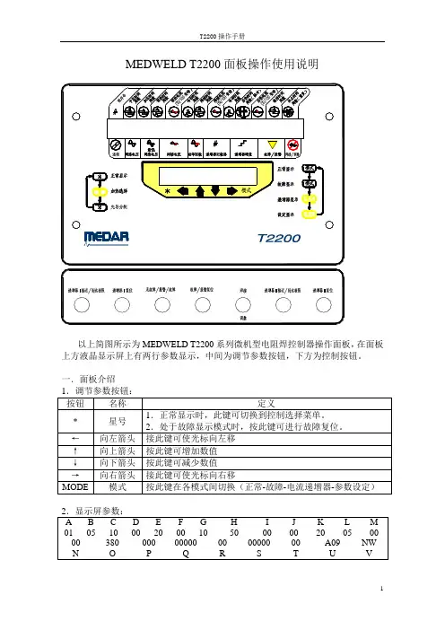
按2秒钟ANCE DISPLAY OPTIONS(前进显示可选项开始)01 HEAT SELECT: 加热方式选择(ON)接通02 PILOT ASSIGNMENTS/SCH INHIBIT: 先导分配/程序禁止(OFF)断开03 C-FACTOR/CURRENT LIMITS: C系数/电流极限(ON)接通04 ANALOG DISPLAY: 模拟量显示(ON)接通05 STEPPER DISPLAY: 递增器显示(OFF)断开06 SETUP DISPLAY: 设定模式显示(ON)接通07 V ALVE MAPPING DISPLAY: 阀路线设置显示(ON)接通08 IO MAPPING DISPLAY: 输入/输出路线设置显示(ON)接通09 RELOAD FROM DEFAULTS: 从默认重新下载(OFF)断开10 NETWORK ADDRESS: 网络地址00-99END OF ADVANCE DISPLAY OPTIONS前进显示选项结束ON(通)1-45-8项可按三.加热方式显示选择(Heat Select)Heat Select加热选择显示用于设定在选定的顺序中向每项焊接功能提供触发热量PRE-HEAT: (A VC/SLOPE) 预热:(自动电压补偿/斜率上升) WELD:(A VC/ACC/A VC-SEAM/ACC-SEAM) 焊接:(自动电压补偿/自动电流补偿/自动电压补偿缝焊/自动电流补偿缝焊)POST-HEAT:(A VC/SLOPE/IMPULSE) 后热:( 自动电压补偿/斜率下降/ 脉冲)C-LMTS: C系数上下限HI: 上限LO: 下限C-FACT: C系数HI CURR LIMIT: 电流上限LO CURR LIMIT: 电流下限SCH 程序号ANALOG WINDOW 模拟量窗口MAX WAIT最大等待时间ACTUAL V ALUE 实际数值STEP:级数TWC:总焊点计数SWC:本级计数RESET:递增器复位PRGM:递增器编程ADDER:递增器递增量TIP DRESS:电极修磨次数光标移动到RESET()处,按↑↓键为递增器复位STEP COUNT为第一阶梯的设定的焊点数按(设定模式显示)(ALERT/FAULT/NONE) 递增器接近极限(报警/故障/无)02 END OF STEPPER: (FAULT/NONE) 递增器到达极限(故障/无) 03 HIGH CURRENT: (ALERT/FAULT/NONE) 电流上限(报警/故障/无) 04 LOW CURRENT: (ALERT/FAULT/NONE) 电流下限(报警/故障/无) 05 HIGH C-FACTOR LIMIT: (ALERT/FAULT/NONE) C系数上限(报警/故障/无) 06 LOW C-FACTOR LIMIT: (ALERT/FAULT/NONE) C系数下限(报警/故障/无) 07 HALF CYCLE: (ALERT/FAULT/NONE) 半周(报警/故障/无) 08 VOLTAGE COMPENSATION: (ALERT/FAULT/NONE) 电压补偿极限(报警/故障/无) 09 INSUFFICIENT LINE VOLTAGE: (ALERT/FAULT/NONE) 网络电压不足(报警/故障/无) 10 EXTENDED WELD: (ALERT/FAULT/NONE) 重焊一次(报警/故障/无) 11 CURRENT COMPENSATION: (ALERT/FAULT/NONE) 电流补偿极限(报警/故障/无) 12 NO ZERO CROSSING SYNC: (ALERT/FAULT/NONE) 无过零同期信号(报警/故障/无) 13 LOW BATTERY: (ALERT/FAULT) 电池电压低(报警/故障) 14 WELD PILOT: (ALERT/FAULT/NONE) 焊接先导(报警/故障/无) 15 SYSTEM COOLING: (ALERT/FAULT) 系统冷却(报警/故障) 16 WELD PROCEED: (ALERT/FAULT/NONE) 继续焊接(报警/故障/无) 17 CHAINED SEQUENCE: (ALERT/FAULT) 连锁顺序(报警/故障) 18 RETRACT PILOT: (ALERT/FAULT/NONE) 回抽先导(报警/故障/无) 19 BEAT MODE: (ALERT/FAULT/NONE) 如果在启动设定参数中选择了BEAT模式,控制器(报警/故障/无) 期望焊接先导在预热功能项开始执行前保持有效,若焊接先导提前失效,就产生这一故障条件.20 NO WELD: (ALERT/FAULT) 调整(报警/故障) 21 HEAT CYCLE LIMIT: (FAULT) 加热周数极限(故障) 22 I/O FAILURE: (FAULT) 输入/输出故障(故障)23 ISO OFF WHEN NEEDED: (FAULT) 当需要时隔离器接触器接通时,隔离接触器断开(故障) 24 CONTROL STOP: (FAULT) 控制器停车(故障) 25 PRESSURE NOT ACHIEVED: (FAULT) 未达到设定压力(故障) 26 ISO CNTR ERR-BRKR TRIPPED: (FAULT) 隔离接触器出错,断路器跳闸(故障) 27 PRESSURE SWITCH: (ALERT/FAULT/NONE) 压力开关(报警/故障/无) 28 SEC CURRENT COIL/BOARD: (FAULT) 次级电流线圈/次级电流电路板(故障) 29 SHOW / HIDE NONE SETUPS: (SHOW/HIDE) 显示或隐藏设置为“无”的设定参数(显示/隐藏) 30 INITIATION ON FAULT: (INHIBIT/ALLOW) 在故障条件下启动(禁止/允许) 31 INDEX PILOT ASSIGN ON REPEAT: (NO/YES) 连续焊时是否使先导分配换档(否/是) 32 SUCCESSIVE SEQUENCING: (NO/YES) 允许或禁止按设定的顺序号依次执行(否/是) 33 TRANSFORMER: (AC-WOUND/DC-STACKED/DC-WOUND/AC-STACKED) 变压器(交流卷绕/直流叠片/直流卷绕/交流叠片) 34 CURRENT LIMIT MODE: (A VERAGE/PEAK) 电流极限模式(平均/峰值) 35 CURRENT MONITOR MODE: (PRIMARY/SECONDARY) 电流监控模式(初级/次级) 36 EXTENDED WELD: (DISABLED/ENABLED) 重焊一次(禁止/允许) 37 HEAT CYCLE LIMIT (0=SEAM): nn (00 - 99) 加热周数极限(0=缝焊)38 HALF CYCLE FIRING: (DISABLED/ENABLED) 半周触发(禁止/允许) 39 ISOLATION CONTACTOR DELAY (SEC): (05) 隔离接触器延时40 ANALOG OUTPUT: (VOLTAGE/CURRENT LOOP) 模拟输出(电压/电流回路) 41 INITIATION FROM RETRACT: (INHIBIT/ALLOW) 在处于回抽状态下启动(禁止/允许) 42 RETRACT MODE: (LATCHED/UNLATCHED) 回抽模式上闩/不上闩43 RETRACT CYLINDER:(AIR-NORMAL/AIR-INVERTED/AIR-OIL-NO/AIR-OIL-NC)回抽缸: (正向气压/反向气压/汽-液-常开/汽-液-常闭)44 MAXIMUM TIP DRESSES: 05最大电极修磨次数45 DATA COLLECTION SAMPLE SIZE: 01样品数据采集大小46 DATA COLLECTION SAMPLE FREQUENCY: 0001样品数据采集频率47 GUN 1 CLOSE TO PRE-BLOCK POS (CY/2): 000枪1闭合到预设的阻挡位置(中开裆)48 GUN 1 ADV ANCE STOP TIME (CY/2): 000用这项参数来编写枪1的动态制动时间, 以周数计49 GUN 1 OPEN FROM BLOCK POS (CY/2): 000枪1位置从阻挡位置(中开挡)动作到全开位置50 GUN 1 OPEN TO BLOCK POS (CY/2): 000枪1位置从全开位置动作到阻挡位置(中开挡)51 GUN 2 CLOSE TO PRE-BLOCK POS (CY/2): 000枪2闭合到预设的阻挡位置(中开挡)52 GUN 2 ADV ANCE STOP TIME (CY/2): 000用这项参数来编写枪2的动态制动时间, 以周数计53 GUN 2 OPEN FROM BLOCK POS (CY/2): 000枪2位置从阻挡位置(中开挡)动作到全开位置54 GUN 2 OPEN TO BLOCK POS (CY/2): 000枪2位置从全开位置动作到阻挡位置(中开挡)55 NOMINAL LINE VOLTAGE: 000标称网路电压56 WAIT FOR LINE VOLTAGE: 000这项参数设定控制器允许继续执行焊接程序的最低网路电压57 LINE VOLTAGE WAIT TIME (CYC) 000这项参数规定了控制器允许等待网路电压超过所设定的最低网路电压的时间(周数)58 MAXIMUM LINE PRESSURE (PSI) 100 最大气路压力(lb/in2英磅/平方英寸)59 STATIC ANALOG 1 OUT V ALVE (PSI): 075 静态模拟1输出阀(lb/in2英磅/平方英寸)这是静态的压力输出,以英磅/平方英寸计, 不是在执行焊接程序时的压力输出60 STATIC ANALOG 2 OUT V ALVE (PSI): 075 静电模拟2输出阀(lb/in2英磅/平方英寸)这是静态的压力输出,以英磅/平方英寸计, 不是在执行焊接程序时的压力输出61 SEC. CURR COIL FACTOR (X1000): 1000次级电流线圈因数62 TIMER #1 (SEC): 000 #1 计时器(焊点计数用)(秒)63 TIMER #2 (SEC): 000 #2 计时器(焊点计数用)(秒)64 SCHEDULE #1 CNT: 000执行程序#1焊点计数65 SCHEDULE #2 CNT: 000 执行程序#2焊点计数66 TIMER #3 (SEC): 000 #3 计时器(焊点计数用)(秒)67 TIMER #4 (SEC): 000 #4 计时器(焊点计数用)(秒)68 SCHEDULE #3 CNT: 000 执行程序#3焊点计数69 SCHEDULE #4 CNT: 000 执行程序#4焊点计数V ALVE 阀序号RET 回抽TXR 变压比ANALOG(PSI) 模拟量(lb/in2英磅/平方英寸)STPR 递增器号FORGE 锻压阀开始周数设置显示按/输出设置显示)OFF/DEFAULT 1 重新装入I/O默认值:断开/默认值1 02 INITIATION TYPE: BINARY/DISCRETE 启动形式二进制/离散式03 V ALVE TYPE: BINARY/DISCRETE 气阀形式二进制/离散式04 PRESSURE TYPE: ANALOG/PRESSURE SELECT 压力形式模拟量/压力选择05 INITIATION MODE: NON BEAT/BEAT 启动模式程序一旦启动就执行到底/在预热功能项前断开启动信号就放弃程序06 ISOLATION CONTACTOR: DISABLED/ENABLED 隔离接触器无效/有效07 INPUT 1:输入1……22 INPUT 16: 输入1623 OUTPUT 1: 输出1…………32 OUTPUT 10: 输出10INPUT 1-16定义如下:NONE 无TIP DRESS MODE 电极修磨模式STEPPER RESET 递增器复位TIP DRESS GROUP 2 RESET 电极修磨第2组复位TIP DRESS GROUP 1 RESET 电极修磨第1组复位GUN 2 CLOSE BACKUP 枪2从大开挡转为小开挡GUN 2 OPEN BACKUP 枪2从小开挡转为大开挡GUN 1 CLOSE BACKUP 枪1从大开挡转为小开挡GUN 1 OPEN BACKUP 枪1从小开挡转为大开挡WELD COUNTER RESET GUN 2 枪2焊点计数复位WELD COUNTER RESET GUN 1 枪1焊点计数复位HEAT DISPLAY SECURITY 阻止在加热显示屏幕上修改PROGRAM SECURITY 阻止程序修改NO STROKE/NO WELD 电极不动作/调整(电极动作但不通电) TRANSFORMER OVERTEMP 变压器过热RETRACT PILOT 2 回抽先导2RETRACT PILOT 1 回抽先导1WELD PROCEED 2 继续焊接2WELD PROCEED 1 继续焊接1PRESSURE SWITCH 压力开关TIP DRESS RESET 电极修磨复位FAULT RESET 故障复位STEPPER RESET GROUP 2 递增器复位组2 STEPPER RESET GROUP 1 递增器复位组1 ISOLATION CONTACTOR SA VER 隔离接触器储器触点节省装置WELD/NO WELD 焊接/调整WELD INITIATE 焊接启动BINARY SELECT 32/PILOT 6 二进位选择32/先导6 BINARY SELECT 16/PILOT 5 二进位选择16/先导5 BINARY SELECT 8/PILOT 4 二进位选择8/先导4 BINARY SELECT 4/PILOT 3 二进位选择4/先导3 BINARY SELECT 2/PILOT 2 二进位选择2/先导2 BINARY SELECT 1-PILOT 1 二进位选择1/先导1 OUTPUT 1-10定义如下:NONE 无输出REQUEST TO WELD 请求焊接FAULT 故障TIP CHANGE REQUIRED GROUP 2 电极更换要求组2TIP CHANGE REQUIRED GROUP 1 电极更换要求组1TIP CHANGE REQUIRED 电极更换要求TIP DRESS REQUEST GROUP 2 电极修磨要求组2TIP DRESS REQUEST GROUP 1 电极修磨要求组1TIP DRESS REQUEST 电极修磨要求GUN 2 CLOSE BACKUP 枪2从大开挡转为小开挡GUN 2 OPEN BACKUP 枪2从小开挡转为大开挡GUN 1 CLOSE BACKUP 枪1从大开挡转为小开挡GUN 1 OPEN BACKUP 枪1从小开挡转为大开挡SCHEDULE ALARM 程序报警ADV ANCE V ALVE 2 向前动作阀2ADV ANCE V ALVE 1 向前动作阀1FORGE 锻压阀WELD/NO WELD MISMATCH 焊接/调整不匹配WELD/NO WELD 焊接/调整PRESSURE SELECT 4 压力选择4 PRESSURE SELECT 3 压力选择3 PRESSURE SELECT 2 压力选择2 PRESSURE SELECT 1 压力选择1END OF HOLD 维持结束RETRACT 2/OHMA BLOCK 2 回抽2/OHMA阻挡位置2 RETRACT 1/OHMA BLOCK 1 回抽1/OHMA阻挡位置1 WATER SA VER 冷却水节省装置STEPPER APPROCHING MAX 递增器接近极限END OF STEPPER 递增器到达极限READY TO WELD 已准备好进行焊接WELD COMPLETE 焊接完毕STEPPER SAM/EOS GROUP 2 递增器接近极限/递增器到达极限组2 STEPPER SAM/EOS GROUP 1 递增器接近极限/递增器到达极限组1ALERT 报警NO FAULT 无故障WELD IN PROGRESS/INIT ACK 焊接进行中/确认启动焊接INTENSIFICATION V ALVE 增压阀V ALVE6/BINARY V ALVE 32 阀6/二进位阀32V ALVE5/BINARY V ALVE 16 阀5/二进位阀16V ALVE4/BINARY V ALVE 8 阀4/二进位阀8V ALVE3/BINARY V ALVE 4 阀3/二进位阀4V ALVE2/BINARY V ALVE 2 阀2/二进位阀2V ALVE1/BINARY V ALVE 1 阀1/二进位阀1关于C-FactorC系数C-FactorC系数是能提供的最大次级电流百分之一变化的电流值.C系数等于焊接过程中总共可获得电流的1%.C系数有各种用途:∙它可用作一个I%值和实际电流值之间的转换系数..∙C系数的变化表达了焊接环境的变化.每次焊接之后,MedWeldT2200计算实际C系数.微处理器将平均次级电流除以焊接时的触发的I%来算出C系数.C系数是:C-Factor=Iprixn/%IxVnominal/Vline=Isec/%IxVnominal/Vline其中C-FactorC系数,Ipri初级电流,n=变压器匝数比,Vnominal额定初级电压,Vline焊接时实际电网电压,Isec次级电流C系数随着次级回路条件的变化而变化.C系数降低表明总的系统容量在减少.当焊机电流回路电阻增加时,这就很明显.由此,又造成次级回路的恶化.(电缆磨损和接触连接处恶化是二个例子.)C系数下降的例子在一个用次级软连接的转台式焊枪机构,焊枪通电时将牵引电缆.此力会造成电缆中多芯导线断裂.当剩下的导线束越来越少,电流通道将会减少,电阻增加.为此,C系数将会下降.可用以下数据来说明:∙控制器在触发下列焊接功能项WELD10CYC10000A焊接10周10000安培∙开始控制器需要53%来取得10,000A.过一段时间,控制器实际需要60%来取得要求的10,000A.∙开始的C系数=10,000A/53%=189.∙最终的C系数=10,000A/60%=167.相反地,在C系数增加的场合,系统的总能力增加.这种C系数的增加是与焊接环境的短路或分流联系起来的.当产生短路或分流后,并非全部电流都通过整个焊接回路,造成电阻减小.这是一个需要十分关心的问题.如果不是全部电流通过焊点,将使焊接电流低于要求值.根据分流的严重程度,很有可能形不成焊点核心.C系数增加的例子在这个例子中,一个机器人用一根无感电缆.机器人的动作使电缆扭曲.由此造成电缆内的导线相互摩擦.这种动作最终使电缆绝缘破坏.一旦出现这种破坏,无感电缆中的导线间开始产生分流.随着分流的增加,通过焊点的电流将会减少,而电流通道将会增加,造成了C系数增加.这可用以下数据来说明:∙焊接控制器在触发下列功能项:WELD10CYC65%I焊接10周65%I∙开始时控制器看到12,450A.∙在发生电缆内部导线短路后,控制器可能看到14,300A.∙开始的C系数=12,450A/65%=192.∙最终的C系数=14,300A/65%=220.C系数能用于提醒维修人员一个焊机的次级回路正在恶化.你能按电流门槛建立起C 系数的上下限以满足焊接过程的需要.当焊接过程测到C系数的上下限被超过,它就激活HIGH/LOWC-FACTORLIMITC系数上下限条件(此条件可在设定参数中定义为Fault故障或Alert报警).∙C系数下限是一个监视条件,通常定义为ALERT报警.∙C系数上限是一个焊接质量事件,通常定义为FAULT故障.LowC-FactorC系数下限C系数下限能测出电缆和导电接触的恶化.如何决定一个下限:在另一个例子中,一个焊接程序在递增器程序结束时需要14,000A.但同时你又不希望超过焊机最大电流容量的90%.这就意味着焊机的最小全电流容量为15,500A.因此,C系数下限为155.HighC-FactorC系数上限C系数上限能测出次级分流.如何决定一个下限例如,一个点焊的应用需要10,000A.,而最大可获得的电流为20,000A.那么C系数为200.但是,当模拟分流条件发现C系数为230时,焊点质量不符标准,那么C系数上限为230.编写焊接顺序本章介绍MedWeldT2200如何编写焊接顺序.其主要方面有进入Normal/Programming正常/编程模式.阅读和理解焊接状态数据."Chaining连锁"几个焊接顺序设定控制器的Weld/NoWeld焊接/调整状态.编写焊接程序是在Normal/Programming正常/编程模式下进的.当接通电源后,控制器会显示3个开始启动屏幕,然后进入Normal/Programming正常/编程模式屏幕.你也能从任何其他模式或屏幕打开或回到这个屏幕.为此,根据需要重复按MODE键.一个同以下例子相似的屏幕会出现:按下列步骤来选择一个焊接顺序:1.如果光标不处于上图的域(1),按键←或→键把它移到那里.2.按↑或↓键来选择要阅读或编辑的顺序.按下列步骤来编写预压周数时间.1.如果光标不处于上图的域(2),按键←或→键把它移到那里.2.按↑键来增加数字或↓键来减少它.按下列步骤来编写加压周数时间.1.如果光标不处于上图的域(3),按键←或→键把它移到那里.2.按↑键来增加数字或↓键来减少它.按下列步骤来编写PRE-HEAT预热脉冲周数时间.1.如果光标不处于上图的域(4),按键←或→键把它移到那里.2.按↑键来增加数字或↓键来减少它.按下列步骤来设定PRE-HEAT预热电流值:1.如果光标不处于上图的域(5),按键←或→键把它移到那里.2.按↑键来增加数字或↓键来减少它.附注:在HeatSelect加热选择的触发模式将会影响如何来编写电流.当选用A VC时,焊接热量是按最大可获得的初级电流百分数来编写.当选用ACC时,焊接热量编写为次级电流值(A.安培数).在Heat Select加热选择显示上所作的任何修改将会使电流值复位到它们的最低值:对A VC为20%,对ACC为00000A.请参阅"加热选择显示".二个冷却周数(域#6和#9)是可编写的.按下列步骤来编写COOL冷却周数时间:1.如果光标不处于上图的域(6)或域(9),按键←或→键把它移到那里.2.按↑键来增加数字或↓键来减少它.1.7编写WELD焊接周数时间1.如果光标不处于上图的域(7),按键←或→键把它移到那里.2.按↑键来增加数字或↓键来减少它.附注:这项数值将受触发模式的影响.若选择A VC或ACC缝焊,当焊接先导为有效时,控制器将一直重复焊接功能项.当撤除先导后,控制器将执行顺序中的下一个功能项.按下列步骤来设定焊接电流值.1.如果光标不处于上图的域(8),按键←或→键把它移到那里.2.按↑键来增加数字或↓键来减少它.附注:请记住:你在HeatSelect加热选择显示中所选定的触发模式将决定焊接热量.对这个设定作的任何修改将使焊接电流复位到它的最低可设定值:对A VC是20%,对ACC是00000A.1.如果光标不处于上图的域(9),按键←或→键把它移到那里.2.按↑键来增加数字或↓键来减少它.按下列步骤来编写后热周数时间.1.如果光标不处于上图的域(10),按键←或→键把它移到那里.2.按↑键来增加数字或↓键来减少它.如果后热功能项用来定义焊接脉冲,则按上述步骤来输入控制器将重复的焊接脉冲数.脉冲由加热和冷却周数组成,其周数则在WELD焊接和COOL冷却功能项中规定.附注:当在HeatSelect加热选择显示中对后热触发模式选定为Impulse脉冲时,此值就不再表示后热周数时间.它代表将提供的焊接脉冲数.(一个焊接脉冲由焊接周数与冷却周数组成.)按下列步骤来设定后热电流值:1.如果光标不处于上图的域(11),按键←或→键把它移到那里.2.按↑键来增加数字或↓键来减少它.附注:若对后热触发模式选择为Impulse脉冲,则该项数值就不会显示,也不能编写.请"先导分配显示".1.11编写维持周数时间1.如果光标不处于上图的域(12),按键←或→键把它移到那里.2.按↑键来增加数字或↓键来减少它.附注:如果焊接顺序被"连锁"到另一个顺序,该功能项就不执行.(在连锁顺序中,祗有最后一个顺序的Hold维持和OFF休止周数才被执行.)1.12编写休止周数时间按下列步骤来编写OFF休止周数时间:1.如果光标不处于上图的域(13),按键←或→键把它移到那里.2.按↑键来增加数字或↓键来减少它.附注:如果这个顺序连锁到另一个顺序,此功能项就不执行.连锁顺序中的最后一个顺序才执行功能项.(除非在设定参数中选用了DUAL双气缸形式),在连锁顺序的重复焊中,重复从第一个顺序的squeeze加压功能项开始.祗有在双气缸形式下,重复才会从连锁顺序中第一个顺序的第一个功能项开始.在OFF休止时间内,ENDOFHOLD维持结束输出有效,此输出保持时间与OFF休止周数相同.2.关于焊接状态数据据.状态信息只表示了收集的数据,不能编写修改.每焊一点,这个显示就更新一次.你无法将光标移到这些域.你祗能修改这一行的的第一个和最后一个域来选择WELD/NOWELD焊接/调整状态和连锁到那一个焊接顺序.这些在以下几节中进行描述.3.连锁顺序你可用显示下一行的第一个域来设置控制器从现在选择的焊接顺序连锁到另一个顺序.这个连锁能力使一个焊接顺序中可增加更多的焊接功能项.在Chaincommand连锁命令域,即下图中的高亮区,通常是设置为00.若不是00,就代表在执行完当前顺序的后热功能项后,"连锁到"那一个焊接顺序号.连锁能提高在一个顺序内的灵活性和焊接能力.用它来加到控制器的固定焊接程序(预热,焊接,后热)中去.一次焊接内通不同焊接电流,更为复杂的操作等成为可能.当MedWeldT2200开始一个连锁顺序,它执行连锁顺序中第一个顺序的每项功能项,直至完成后热功能项.然后,跨越HOLD维持和OFF休止而直接跳到它"连锁到"的焊接顺序.附注:控制器不执行连锁到新焊接顺序的启动功能项(预压,加压和预热).它跳到焊接和后热功能项,并核查是否再连锁到第三个顺序.如果焊接和后热功能项没有连锁到其他顺序,控制器就执行HOLD维持和OFF休止功能项.如果它被连锁到另一个顺序,则就再一次跨越HOLD维持和OFF休止周数而跳到新顺序的焊接功能项.理论上,MedWeldT2200能执行一个由所有50个顺序组成的连锁顺序.(任何连锁顺序中,Chaincommand连锁命令域设为0的顺序是它最后一个顺序.)但很少实际应用中会需要这么复杂的连锁.正常情况下,一个连锁顺序仅由二到三个顺序组成.也有可能重复一个连锁焊接顺序.此时将连锁顺序的最后一个顺序的OFF休止时间不设为0即可.在OFF休止周数内,控制器处理焊接故障并激活ENDOFHOLD维持结束输出(如果没有测到故障的话).这使控制器在测到故障情况下能在接到ENDOFHOLD维持结束输出通知启动另一次焊接前仃止任何自动操作.连锁并非是典型的应用.附注:在一个连锁顺序中,每个顺序都祗允许用一次.若编写二次,控制器会发出CHAINEDSEQUENCEERROR连锁顺序出错故障.4.选择WELD/NOWELD焊接/调整状态显示下一行的另一个可编写的域是WELD/NOWELD焊接/调整域.此域表示当前选择的状态.此状态可以改变.WELD焊接模式允许触发脉冲去接通焊接变压器初级.在NOWELD调整模式,控制器运行程序但不向工件提供焊接电流.附注:此域仅表示焊接电流是否被允许,它不表明最后一次焊接是否提供了焊接电流.如果控制器处于NOWELD调整,(不论是在Normal/Programming正常/编程显示上被禁止或是由于SYSTEMCOOLING/NOWELD系统冷却/调整输入成为无效),控制器将在不通焊接电流的情况下运行程序.在故障显示区(域13)将显示SYSTEMCOOLIING/NOWELD系统冷却/调整故障.欲从Normal/Programming正常/编程模式改变当前选择的模式(WELD焊接或NOWELD调整),按下列步骤操作:按←或→键将光标移到Normal/Programming正常/编程屏幕上的WELD/NOWELD 焊接/调整域.欲选择WELD焊接,按↑键,欲选择NOWELD调整,按↓键.欲选择Fault故障或StepperStatus递增器状态模式,按MODE;或用←或→键继续进行编程工作.I/O定义。


USB2200数据采集卡 使用说明书USB简介USB(UNIVERSAL SERIER BUS)又称之为通用串行总线,不仅仅简单地将计算机和外设连接在一起,还把我们带进了一个全新的PC机时代。
USB是您进行数字图象处理的最佳选择,同时她也为数字化设计提供了无限的创造空间。
为什么USB越来越受到用户的青睐呢?第一.USB实现了那些一直渴望简单、直接、快速连接外设到PC机的使用者的梦想。
添加一个传统外设,首先您必须要弄清那些复杂的端口序列中那一个才是您需要的。
其次,在通常情况下,您还不得不拆开PC机,安装所需要的板卡,并且选择跳线,诸如中断设置等,这些都是非常麻烦的事情,甚至会使一些用户害怕添加外设。
USB使添加外设变得十分简单,任何人都可以轻松的做到。
首先,USB用一个标准的插拔端口代替了所有的不同种类的串并口。
使用USB连接PC机和外设,您只须把他们连接在一起就行,剩下的事情USB会自动帮您完成。
他就像是给您的PC机添加一个新的功能。
您再也不须拆开您的PC机,也不必担心插入板卡,DIP跳线和中断设置。
第二,USB的即插即用功能。
当您需要接入外设时,甚至不必关闭电源重启计算机,只要插入便可运行!PC自动检测外围设备并且配置必要的软件。
因此,它不仅广泛用于各种台式机,还给笔记本PC带来了新的生机。
而当您需要移走外设时,只须拔走USB插头即可。
也许您会问“我可以同时接多个外围设备吗?PC机有足够的USB接口吗”? USB当然可以同时连接多个外围设备;许多PC机有两个以上的USB端口,而集线器——一种特殊的USB外围设备,可以附属多个USB端口,当您需要使用多于两个外设时,接入一个集线器即可。
第三.USB传输数据的速度非常快,达到12Mbit,而在新发行的USB2.0版本中,其传输速度居然达到480Mbit。
USB2200使用说明书一、概述USB2200为中断计数及开关量输入输出板,是和USB总线兼容的模块板,可经USB电缆直接连入计算机,又因它具有体积小,即插即用等特点,因此是便携式系统用户的最佳选择。

MW2200_操作⼿册(⽊⼯数控开料机⽤)MW ⽊⼯机械MW2200 操作⼿册Advantech-LNC Technology Co.,⽬录⽬录 (i)1.操作⾯板 (3)1.1.主画⾯区 (3)1.2.模式区 (4)1.3.操作区 (5)2.群组说明 (6)2.1.监视群组 (6)2.2.编辑群组 (6)2.3.补偿群组 (7)2.4.诊断群组 (7)2.5.维护群组 (7)3.画⾯功能说明 (9)3.1.扫码开档93.2.断点再启93.3.档案管理103.3.1.删除/ 更名/ 复制 (10)3.3.2.U 盘汇⼊/ 汇出 (11)3.3.3.⽹盘汇⼊/ 汇出 (11)3.4.排程加⼯123.5.⾃动对⼑133.6.⼑库设定143.6.1.排⼑设定143.6.2.⽃笠⼑库设定143.6.3.排钻设定153.7. 备份 (15)3.8.系统更新163.9.快速还原173.10.语系设定174.内建功能说明 (18)4.1.⾃动上下料 (18)4.2.主轴功能194.2.1.主轴转速相关194.2.2.主轴⽓缸194.2.3.主轴吸尘罩204.3.吸附功能204.4.定位功能214.5.除尘功能224.5.1.单⼯位除尘224.5.2.双⼯位除尘225.参数设定 (23)5.1.⽤户参数 (23)5.2.系统参数 (25)BCA1. 操作⾯板MW2200 画⾯如下图,分为三⼤区域,各区使⽤说明参考如下 - A : 主画⾯区请参考 1.1 - B : 模式区请参考 1.2 -C : 操作区请参考 1.31.1. 主画⾯区主画⾯区主要分成三部分,说明如下:-标题栏:显⽰⽬前所选择的加⼯⽂件、系统模式、系统状态、所选页⾯、时间与使⽤者层级。
-页⾯:显⽰⽬前所选页⾯的内容信息,会依选择不同页⾯⽽有不同的内容。
-按钮选单:可以进⾏页⾯切换与功能选择。
左边的^ (上箭头)代表上⼀层选单;右边的> (右箭头)代表下⼀页选单。
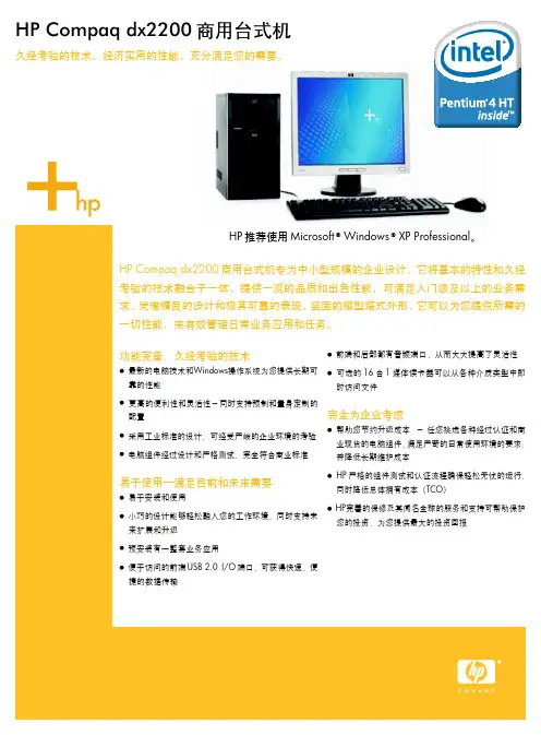
HP Compaq dx2200商用台式机功能完备、久经考验的技术●最新的电脑技术和Windows操作系统为您提供长期可靠的性能●更高的便利性和灵活性-同时支持预制和量身定制的配置●采用工业标准的设计,可经受严峻的企业环境的考验●电脑组件经过设计和严格测试,完全符合商业标准易于使用—满足目前和未来需要●易于安装和使用●小巧的设计能够轻松融入您的工作环境,同时支持未来扩展和升级●预安装有一整套业务应用●便于访问的前端USB 2.0I/O端口,可获得快速、便捷的数据传输●前端和后部都有音频端口,从而大大提高了灵活性●可选的16合1媒体读卡器可以从各种介质类型中即时访问文件完全为企业考虑●帮助您节约升级成本-任您挑选各种经过认证和商业现货的电脑组件,满足严苛的日常使用环境的要求,并降低长期维护成本● HP严格的组件测试和认证流程确保轻松无忧的运行,同时降低总体拥有成本(TCO)● HP完善的保修及其闻名全球的服务和支持可帮助保护您的投资,为您提供最大的投资回报久经考验的技术,经济实用的性能,充分满足您的需要。
HP Compaq dx2200商用台式机专为中小型规模的企业设计,它将基本的特性和久经考验的技术融合于一体,提供一流的品质和出色性能,可满足入门级及以上的业务需求。
凭借精良的设计和极其可靠的表现,坚固的微型塔式外形,它可以为您提供所需的一切性能,来有效管理日常业务应用和任务。
HP推荐使用Microsoft® Windows® XP Professional。
HP Compaq dx2200商用台式机HP推荐使用Microsoft® Windows® XP Professional处理器英特尔® 赛扬® D 326处理器(2.53GHz、256KB 二级高速缓存、533MHz前端总线)英特尔® 赛扬® D 331处理器(2.66GHz、256KB 二级高速缓存、533MHz前端总线)英特尔® 赛扬® D 336处理器(2.80GHz、256KB 二级高速缓存、533MHz前端总线)英特尔® 赛扬® D 341处理器(2.93GHz、256KB 二级高速缓存、533MHz前端总线)英特尔® 赛扬® D 346处理器(3.06GHz、256KB 二级高速缓存、533MHz前端总线)英特尔® 赛扬® D 351处理器(3.20GHz、256KB 二级高速缓存、533MHz前端总线)含超线程(HT)技术1的英特尔® 奔腾® 4处理器英特尔® 奔腾® 4 521处理器(2.80GHz、1MB 二级高速缓存、800MHz前端总线)英特尔® 奔腾® 4 531处理器(3.0GHz、1MB 二级高速缓存、800MHz前端总线)英特尔® 奔腾® 4 620处理器(2.80GHz、2MB二级高速缓存、800MHz前端总线)英特尔® 奔腾® 4 630处理器(3.0GHz、2MB二级高速缓存、800MHz前端总线)英特尔® 奔腾® 4 640处理器(3.20GHz、2MB二级高速缓存、800MHz前端总线)英特尔® 奔腾® 4 650处理器(3.40GHz、2MB二级高速缓存、800MHz前端总线)操作系统Microsoft® Windows® XP Professional SP2;Microsoft® Windows® XP Home SP2 Free DOS芯片组ATI Radeon Xpress 200芯片组内存256MB PC2-5300 DDR2 SDRAM(667MHz)非ECC单通道512MB PC2-5300 DDR2 SDRAM(667MHz)非ECC单通道1GB PC2-5300 DDR2 SDRAM(667MHz)非ECC单通道*注:HP Compaq dx2200的内存控制器支持频率为630MHz的PC2-5300内存硬盘40 GB串行ATA 1.5Gb/s和80、160或250 GB串行ATA 3.0Gb/s硬盘*(7200 rpm)*注:HP Compaq dx2200的串行ATA接口支持最高可达1.5 Gb/s的数据传输速率。
gr2200的用户手册
gr2200是一款颇具特色的电子产品,它采用最新的技术设计,具有出色的性
能和功能。
为了更好地使用和了解这款产品,用户需要仔细阅读本手册,掌握相关信息。
首先,gr2200的外观设计简洁大方,采用高品质材料制成,手感舒适。
其屏
幕显示清晰,操作界面简单直观,用户可以轻松上手。
同时,gr2200还具有多种
颜色可选,满足不同用户的审美需求。
其次,gr2200具有丰富的功能,包括但不限于通讯、娱乐、办公等,满足用
户在日常生活中的各种需求。
用户可以通过gr2200进行通话、短信、邮件等各种
通讯功能,方便快捷。
此外,gr2200还支持多种应用软件的安装和使用,让用户
享受更多乐趣。
再次,gr2200的性能表现优异,响应速度快,稳定性强。
无论是处理大型文
件还是运行多任务,gr2200都能轻松胜任,不会出现卡顿现象。
同时,gr2200的
电池续航能力也很强,用户可以长时间使用,不必频繁充电。
此外,gr2200还具有一些人性化设计,例如支持指纹识别、面部解锁等功能,保障用户的隐私安全。
同时,gr2200还支持多种语言设置,方便不同国家和地区
的用户使用。
总的来说,gr2200是一款功能强大、性能稳定的电子产品,用户可以放心购
买和使用。
通过本手册的详细介绍,相信用户可以更好地了解gr2200的特点和优势,更好地使用这款产品。
希望用户在使用gr2200的过程中能够有更好的体验和
享受。
感谢您选择gr2200,祝您生活愉快!。
This manual is for the exclusive use of licensees and employees of McDonald’s Systems Inc.Manufactured by:H&K International2200 Skyline DriveMesquite, TX 75149U.S.A. Telephone: (214) 818-3500Fax: (214) 818-3596Distributed by:H&K International2200 Skyline DriveMesquite, TX 75149U.S.A. Telephone: (214) 818-3500Fax: (214) 818-3596(H&K Model Number HCMF30-02-LH&RH, HCMF460-02)High Capacity Modular Freezer-220-240VTable of ContentsTable of Contents (2)Introduction (3)Installation Instructions (4)Inspection (4)Uncrate the Unit (4)Remove Packing & Loose Components (4)Wash and Sanitize Unit Interior & Shelving Components (5)Operating Instructions (5)Connect to Power Source (5)Start-up (5)Temperature Setting (6)Loading and Restocking (6)Store Closing Procedure (7)Cleaning (7)Exterior Cleaning (7)Interior Cleaning (7)Preventative Maintenance (8)Empty and Clean the HCMF (Weekly) (8)Clean the Condenser Coils (Quarterly) (9)Product Warranty (10)Troubleshooting (11)Parts List (12)Parts Ordering and Service (13)Wiring Diagram (15)IntroductionThe Top Breathing High Capacity Modular Freezer is a portable unit designed to hold 10:1, 4:1, and 3:1 boxes at the desired temperature during normal and peak sales periods. The HCMF is ideal for storing beef boxes but other frozen items may be stored as well. Access to the product is through a self-closing, sliding door on the top of theunit and product replenishment is accomplished through a front hinged door.Required clearance around appliance:Sides: Designed for flush installationTop: 6” [152mm] clearanc e required above unit. Back : 1” [25mm]. Clearance provided by bumpers.Maximumloading per shelf: 90lbs [41 kg]Note: Do not pack the unit with excess product as this might lead to improper air flow in the cabinet which can adversely affect operation and potentially void warranty of the unit.Climate Class: 3 (25°C/77°F), possible operation up to Class 5 (40°C/104°F)Installation InstructionsInstallation of this equipment must be completed by qualified personnel in compliance with all manufacturer’s instructions and local building, food safety and electric codes.InspectionUpon receipt, examine the equipment carefully for any damage. If damage has occurred, notify the freight carrier and H&K immediately.Uncrate the UnitThis unit will arrive crated in a skid-mounted carton.Caution! The shipping container may have staples, nails, banding undertension and possible wood splinters, which can cause injuries. Weargloves and eye protection to reduce the risk of injury when uncrating.▪Cut the banding holding the cardboard carton to the shipping pallet, using heavy scissors or tin snips. Use caution to avoid contact with cut banding.▪Lift the cardboard carton straight up and off the unit.▪Cut the banding that holds the refrigerator to the shipping pallet or skid.Use caution to avoid contact with the cut banding.*Note: Leave unit on skid until ready to install▪Peel the protective adhesive film from all exposed areas (front, sides, and interior).Caution! This unit is very heavy, do not attempt to remove this unit fromits packaging without assistance.Remove Packing & Loose ComponentsRemove any tape and foam blocking used to secure the loose components.WARNING: Keep clear of obstruction all ventilation openings in theappliance enclosure or in the structure for building-in.Wash and Sanitize Unit Interior & Shelving ComponentsNote!Use only McDonald’s approved cleaning and sanitizing agentsaccording to instructions.Wipe down, sanitize and dry the freezer interior.Pre-Installation ChecklistOperating InstructionsWARNING: Do not store explosive substances such as aerosol cans witha flammable propellant inside the appliance.WARNING: Do not use electrical appliances inside the food storagecompartments of the appliance, unless they are of the type recommendedby the manufacturer.Connect to Power SourceInsert the plug of the HCMF into a standard 220-240V. outlet. The HCMF contains a compressor and should not be used on the same circuit with other motors or heavy demand appliances.Start-upThe power switch is located on the backside of the condensing unit housing on top. This switch will illuminated red with activated, indicateding that the refrigeration system is operating. Allow the HCMF to run for one hour prior to loading with product to pulldown to operating temperature.Temperature SettingThe HCMF has been tested and preset at the factory to maintain a temperature between -10ºF (-23°C) and 0ºF (-18°C). The temperature controller located on the front panel displays the internal temperature of the refrigerator. This unit will be configured to run in Celsius temperature mode. If Fahrenheit mode is desired, consult HK Service.To view current set point or if the temperature is not reading within the range specified above, the thermostat can be adjusted using the following procedure:Press and hold the “ i " button on lower left corner of controller to view the setpoint. Press the up or down arrow keys to the right to reach the desired setpoint. Factory limits are set to prevent unit from being set too cold or too warm.Loading and Restocking▪ DO NOT over-load the HCMF case. All refrigeration requires good air circulation to maintain uniform temperatures.▪ DO NOT let plastic bags, packaging or containers block or obstruct the Evaporator air intake openings at the top of the case.▪ DO NOT leave the door open, except to remove product or to restock.Caution! Do not adjust the set point below -13ºF or -25ºC. Doing so may result in excessive ice buildup on the cooling coils, the unit not holding a safe temperature, and potential damage to the compressor.Store Closing ProcedureThe HCMF is designed for continuous operation. Consult your store manager or operations director for guidance on product storage.CleaningCaution! Do not use a pressurized spray to clean the HCMF.Caution!Do not use abrasives or strong chemicals to clean any surfaces ofthe HCMF.Warning! Do not spray liquids directly onto the power switch, into thecompressor compartment at the top of the cabinet, or into the evaporator.Doing so will void the warranty and risk serious personal injury.Exterior CleaningThe exterior of the unit should be cleaned with EXCEED Glass & Multi-Surface Cleaner. Do not use abrasive cleaners to clean the exterior of the cabinet as this might damage the stainless steel finish. Do not use steel wool or any strong chemicals.Interior CleaningThe anodized aluminum interior of the refrigerator can be cleaned using a soft sponge and EXCEED Glass & Multi-Surface Cleaner. Do not allow liquid to puddle in the unit. Wipe the inner liner dry after cleaning.Preventative MaintenanceEmpty and Clean the HCMF (Weekly)Once a week the unit should be shut down, emptied and given a thorough cleaning, as follows:▪ Turn OFF power at switch. ▪ Unplug unit from power outlet.▪ Open doors, and remove all product and put into frozen storageelsewhere.▪ Clean, sanitize and dry the interior and exterior compartment, to include:back, sides, top, and floor. ▪ Plug in cord at outlet. ▪ Turn ON power switch.Allow case to run for at least one hour to return to target operating temperature of -10°F (-23°C) to 0° F (-18°C ) before reloading or stocking product.WARNING! Verify freezer is disconnected from the power source before attempting any preventative maintenance. Failure to disconnect the electric power could result in electric shock, burns, injuries or death.CAUTION! The fins on a condenser coil are very sharp, and some refrigeration components can be very hot, resulting in possible cuts and/or burns. Avoid physical contact with the fins on the condenser coil or any related refrigeration lines. Gloves are recommended when accessing the internal components of any refrigerated equipment.Note! Use only EXCEED Glass & Multi-Surface Cleaner, according to instructions.WARNING! Failure to properly perform scheduled preventativemaintenance may void manufacturer’s warranty.Clean the Condenser Coils (Quarterly)Figure 2Figure 3Install access panel in reverse order of removal. Plug the HCMF back in and turn on the powerProduct WarrantyH&K Dallas, Inc. makes the following limited warranties to the original purchaser only for this equipment and replacement parts:H&K warrants all components to be free of defects in material and workmanship, if properly installed, operated and maintained, for a period of (2) years from the date of the delivery.The company’s obligation under this warranty is limited to repairing or replacing any part or parts of the refrigerator determined to be defective by an authorized representative of H&K.The company reserves the privilege of determining if such repairs are to be made in the field or at the H&K factory.The company assumes no liability for expenses or repairs made by other parties except by written consent.Corrections of such defects by repair or replacement shall constitute fulfillment of all company obligations to the purchaser.H&K shall not be liable for loss, damages or expenses arising from misuse, abuse, alteration, accident or improper installation of the freezer such as:Improper or unauthorized repair;Failure to follow proper installation instruction;Improper maintenance;Damage in shipment;Abnormal use;Improper power supply;Natural disaster;Special ConditionsThis warranty also does not cover:Overtime or holiday charges;Consequential damages (the cost of repairing or replacing other property which is damaged), loss of time, profits, use of any other incidental damages of any kind. Expected life of this equipment is 7 to 10 years provided that it is maintained properly through H&K approved suppliers using only approved component parts and that the unit is cleaned regularly and not abused.TroubleshootingParts List5Parts Ordering and ServiceReturns Contact:H&K Dallas, Inc. 2200 Skyline Drive Mesquite, TX 75149 (214) 818-3500Damages and ShortagesUpon receipt, examine the equipment carefully for any damage. If damage has occurred, notify the carrier and H&K Dallas, Inc. immediately.Service and Parts Contact: H&K Dallas, Inc.2200 Skyline Drive Mesquite, TX75149 (214) 818-3500Additional Information (Where Applicable)Disconnect all power sources before attempting any service or repair work.Caution! A qualified licensed technician should perform all service and repair. WARNING : Do not use mechanical devices of other means to accelerate the defrosting process, other than those recommended by the manufacturer.WARNING : Do not damage the refrigeration circuit.WARNING : If the supply cord is damaged, it must be replaced by themanufacturer, its service agent, or similarly qualified person in order to avoid a hazard.WARNING : Where applicable, this appliance can be used by children aged from 8 years and above and persons with reduced physical, sensory or mental capabilities or lack of experience and knowledge if they have been given supervision or instruction concerning use of the appliance in a safe way and understand the hazards involvedWARNING : Children shall not play with the appliance.WARNING : Cleaning and user maintenance shall not be made by children with supervision.Wiring Diagram(s)Notes。
东讯智慧机电监测系统MMK-2200智慧振动规(ST) MMK-2210智慧振动规(SC) 操作使用手册目录簡介 (3)东讯智慧振动规 (4)1. 系统组合 (4)2. 振动规形式 (4)3. 系统容量 (5)4. 设备接线 (5)5. 接线方法 (6)6. 设备尺寸 (7)7. VB-200ST/VB-200SC 视图 (7)8. 振动规建议安装位置 (8)9. 安装注意事项 (10)10. 安装参考范例 (11)10-1 垂直(vertical) (11)10-2 水平(Horizontal) (12)10-3 轴向(Axial) (13)设备设定 (14)1. 马达配置 (14)2. VB200 设定 (14)APP应用软件操作 (17)簡介东讯智慧机电监测系统包括数据转换基站 AG-300 Plus ,温度传感器TT-300,加速度计VB-200和多功能电力仪表PM-300等。
适用于测量电源面板,机电,旋转机械市场的温度,振动和功率数据。
MMK-2200/2210智慧振动规 VB-200提供精确的旋转机电振动测量数据,可以让您轻松管理您的制造机电设备,确保您的设备处于健康状态,并预防灾难性停机。
马达 风扇发电机帮浦 变频器压缩机ADSL 调制解因特网位率 = 9600位率 = 115200 智慧振动规温度, 电压, 电流功率, 电能…等等传感器及仪表VB-200SC VB-200ST东讯智慧振动规东讯智能机电监测系统系列商品产品内容如下:本手册提供MMK-振动规ST(MMK-2200)和MMK-振动规SC(MMK-2210)的操作使用说明.1.系统组合(1)VB-200ST : 外贴式振动感知器(2)VB-200SC : 锁镙式振动感知器(3)VB-200STU : 磁吸式振动感知器(Pro-3200振动诊断仪专用)(4)智慧手机APP (iOS, Android)(5)操作使用手册(6)其它联机相关附件2.振动规形式2.1 VB-200ST : 底下为双面胶,可黏贴式振动规(此为产品示意图, 最终版本以实物为准)。
数字视频切换台S E-2200目录警告与注意事项.........................................................................................................................................3 废弃处理.....................................................................................................................................................3 装箱清单.....................................................................................................................................................4 SE-2200连接方法.....................................................................................................................................4主机前面板介绍........................................................................................................................................... 5主机后面板介绍.. (5)6 后面板的连接方法............................................................................................................................. 控制面板.. (8)按键功能介绍...................................................................................................................................... 9 菜单设置介绍..............................................................................................................................................14 如何连接CG-200与SE-2200..................................................................................................................16 SE-2200的视频层.....................................................................................................................................19 画中画功能介绍.. (20)画中画设置...........................................................................................................................................20 画中画预监与画中画主输出..................................................................................................................20 如何设置画中画的视频源.................................................................................................................20 下游键功能介绍.........................................................................................................................................21 音频设置 (22)音频跟随视频.......................................................................................................................................23 音频指派功能........................................................................................................................................23 音频菜单设置如何处理单个音频源——解嵌SDI 或HDMI 音频.....................................................................................24 .......................................................................................................................25 不同的加嵌音频源之间的切换...........................................................................................................25 如何矫正T-bar 设置...................................................................................................................................26 GPI 远程控制设置......................................................................................................................................27 SE-2200的TALLY 输出............................................................................................................................27 SE-2200设置范例.....................................................................................................................................28 尺寸规格.....................................................................................................................................................29 特点说明.. (30)质保说明标准质保•datavideo 设备质保年限为一年,质保期自购机日期开始计算。
Safety precautionsProduct componentsOptional accessoriesNames of each partsProduct DimensionCables and ConnectorsPower ConnectionLAN ConnectionRS485 ConnectionRelay ConnectionDigital Input ConnectionWiegand Input/OutputOutputInstallation of Wall-mount BracketInstallation ReferenceSpecificationElectrical SpecificationFCC Rules Contents35671011141618202325262728313233The list below is to keep user’s safety and prevent any loss. Please read safety precautions carefully before use.Do not install the device in aplace subject to direct sunlight, humidity, dust or soot.Do not place a magnetnear the product.Do not place the device nextto heating equipments.Be careful not to let liquid like water, drinks or chemicalsleak inside the device.Clean the device often to remove dust on it.In cleaning, do not splash water on the device but wipe it out with smooth cloth or towel.Safety precautionsIt may cause a damage ora failure to the product.It may cause a failure.Do not drop the device. Do not damage the device.Do not disassemble, repair or alter the device.Do not let children touch thedevice without supervision.Do not use the device for any other purpose thanspecified.Contact your nearest dealer incase of a trouble or problem.The warranty does net apply to anyproduct damage cause by anarbitrary installation or repair.Safety precautionsThe list above is to keep user’s safety and prevent any loss. Please read safety precautions carefully before use.Product componentsXpass bracket Wall mounting screws(2 ea)Knife Blocks (2 ea)Shrinkable Tubes Software CDExtended Ethernet CableBasic componentsThe components shown above may differ depending on the installation environment.Plastic stand Secure I/OOptional accessoriesExtended bracket adaptorNames of each partsLED statusInitialization of network settingWhen you install the Xpass or forget the network setting’s value of Xpass in use, can initial the network setting’s value (TCP/IP address, RS-485 setting) in the switch of Xpass’s back side as follows;Product Dimension < Extended bracket >< Front View >< Bracket >< Side View >(unit : mm)Cables and ConnectorsNo Pin Name Full Name Color1485 GND485 GND White (black string)2WGD GND Wiegand-GND Black3485 -485 -Yellow (black string)4WGD D1Wiegand-1White5485 +485 +Blue (white string)6WGD D0Wiegand-0Green7IN 1Input-1Brown8RLY NO Relay Open Gray (white string)9IN GND Input-GND Gray10RLY COM Relay Com Green (white string)11IN 0Input-0Purple12RLY NC Relay Close Orange (black string)13TX+ TX+ (LAN)Pink14PWR IN+Power IN+Red15TX-TX-(LAN)Orange16PWR IN-Power IN-Black (white string)17RX+ RX+ (LAN)Blue18PWR OUT+Power OUT+Light Blue19RX-RX-(LAN)Yellow20PWR OUT-Power OUT-Black (white string)21VB1VB1Green (black string)22VB2VB2Brown (white string)23VB1VB1Green (black string)24VB2VB2Brown (white string)Switch485WiegandRelayYellow (black string)485-11Purple IN 07Brown IN 18GrayIN GND 9Blue (white string)485+10White (black string)485 GND12Black WGD GND6White WGD D15Green WGD D04Gray (white string)RLY NO 3Green (white string)RLY COM 2Orange (black string)RLY NC 1ColorPin Name Cable Cables and ConnectorsBlack (white string)POWER IN -3PowerRedPOWER IN + 1Light BluePOWER OUT +Black (white string)POWER OUT -ColorPin Name Adaptor ConnectorCable SpecificationEthernet extension cableGreen (black string)VB15Green (black string)VB16Brown (white string)VB27Brown (white string)VB28Orange TX-3LANPinkTX+4Blue RX+2Yellow RX-1ColorPin Name LAN Connector LAN cable87546321Modular Jack (A)87651234Connector (B)Green VB1Red VB1Brown VB2GrayVB2Black RX+Yellow RX-Orange TX-Blue TX+Color Pin NamePower Connection 112V ±10%, at least 500mA.Comply with standard IEC/EN 60950-1.To share the power with other devices, use a power supply with higher current ratings.Recommended power supplyBlack (white string)PWR IN-16RedPWR IN+14Color Pin Name PinPower Connection 2Please use the distance of LAN cable within 100m in case of POE power.Recommended power supplyLAN ConnectionLAN Connection (Direct connection with PC)RS485 Connection for Host CommunicationBlue (white string)485 +5Yellow (black string)485 -3White (black string)485 GND 1Color Pin Name PinRS485 Connection for Secure I/OMax number of devicesBlue (white string)485 +5Yellow (black string)485 -3White (black string) 485 GND1ColorPin NamePinMaximum eight(8) devices (including Master) interworks in an RS485 loop.Relay Connection –Fail safe lockOrange (black string)RLY NC12Green (white string)RLY COM 10ColorPin Name PinRelay Connection –Fail secure lockGreen (white string)RLY COM10Gray (white string)RLY NO 8Color Pin Name PinRelay Connection -Automatic doorGreen (white string)RLY COM10Gray (white string)RLY NO 8Color Pin Name PinDigital Input Connection (Alarm, Emergency S/W)PurpleIN 011Gray IN GND 9Brown IN 17Color Pin Name PinDigital Input Connection (RTE, Door sensor)PurpleIN 011Gray IN GND 9Brown IN 17Color Pin Name PinWiegand Input Wiegand Input/OutputWiegand OutputGreenWGD D06WhiteWGD D14BlackWGD GND2ColorPin NamePinGreenWGD D06WhiteWGD D14BlackWGD GND2ColorPin NamePinOutputBlack (white string)PWR OUT -20Light Blue PWR OUT +18Pin Pin Name Color10RLY COM Green (white string)12RLY NC Orange (black string)Caution : Max. 700mA is supplied using adapter for the external output.Be careful to satisfy the power capacity in use.Fix wall mount bracket on a wall using wall mounting screwsHook Xpass on the wall mount bracketInstallation of Wall-mount BracketFix Xpass and wall mounting bracket using a wall mounting screw.Installation Reference 1 -Stand aloneInstallation Reference 2 –Standalone (Secure)Installation Reference 3 –NetworkSpecification40000 user User Capacity50000 log Log CapacityIP 65 class IP RateCPU32 bit Micro-processor Memory8MB FLASH + 16MB SDRAM RF Card13.56 MHz Mifare (XPM)125 KHz EM Prox (XPE)125 KHz HID Prox (XPH)Network interfacesTCP/IP, RS485 SoundMulti-tone buzzer LEDMulti-color LED RTCLithium-ion rechargeable batteries I/ORelay x 1Tamper x 1Switch input x 2 Wiegand x 1Power12Vdc, POE Operating Temperature-20 ~ 50°C Size45 x 130 x 27mm (W x H x D ) Certificates CE, FCC, KCC, IP65It may be occurred the risk of explosion for improper replacement of battery. Please use the specified battery according to proper instruction.Caution for RTC BatteryMin.Typ.Max.NotesPowerVoltage (V)10.81213.2Use regulated DC power adaptor onlyCurrent (mA)-140Switch InputVIH (V)-TBD-VIL (V)-TBDPull-up resistance (Ω)- 4.7k-The input ports are pulled up with 4.7k resistors TTL/Wiegand OutputVOH (V)-5-VOL (V)-0.8-Pull-up resistance (Ω)- 4.7k-The outputs ports are open drain type, pulled up with 4.7k resistors internallyRelaySwitching capacity (A)--10.330V DC125V ACSwitching power (resistive)--30W37.5VADCACSwitching voltage (V)--110125DCACElectrical SpecificationChanges or modifications not expressly approved by the manufacturer responsible for compliance could void the user’s authority to operate the equipment.This device complies with part 15 of the FCC Rules. Operation is subject to the following two conditions: (1) This device may not cause harmful interface, and(2) this device must accept any interface received, including interference that may cause undesired operation.This equipment has been tested and found to comply with the limit of a Class B digital device, pursuant to Part 15 of the FCC Rules. These limits are designed to provide reasonable protection against harmful interference in a residential installation. This equipment generates, user and can radiate radio frequency energy and, if not installed and used in accordance with the instructions, may cause harmful interference to radio communications.However, there is no guarantee that interference will not occur in a particular installation; if this equipment does cause harmful interference to radio ortelevision reception, which can be determined by turning the equipment off and on, the user is encouraged to try to correct the interference by one or more the following measures:1. Reorient / Relocate the receiving antenna.2. Increase the separation between the equipment and receiver.3. Connect the equipment into an outlet on a circuit difference from that to which the receiver is connected.4. Consult the dealer or an experienced radio/TV technician for help Caution Warning Information to UserFCC Rules。