DRT系列IGBT驱动变压器选型指南
- 格式:pdf
- 大小:68.17 KB
- 文档页数:2
IGBT栅极驱动电阻的选择和计算韩朋乐【摘要】栅极电阻对IGBT的动态特性有很大影响,因此对栅极驱动电阻的选择进行探讨,分析了栅极电阻选择不当可能引发的问题,并给出了选择办法,最终通过一种实际的计算方式进行了计算分析.【期刊名称】《通信电源技术》【年(卷),期】2019(036)003【总页数】3页(P36-38)【关键词】栅极电阻;IGBT;动态特性【作者】韩朋乐【作者单位】国家知识产权局专利局专利审查协作河南中心,河南郑州 450001【正文语种】中文0 引言IGBT是常用的电力电子开关元件,其驱动输入端呈现容性。
当使用PWM信号对IGBT进行控制驱动时,信号会通过栅极驱动电阻对器件的输入端进行充放电。
因此,栅极电阻对IGBT的开关时间、损耗等开关参数有重要影响,也决定了开关过程的EMI干扰和电压、电流的上升下降速率。
所以,栅极驱动电阻的大小对IGBT 驱动电路的设计重要性不言而喻。
现有的各种数据手册中一般仅仅给出驱动电阻的测试典型值,并未对其大小进行选择计算。
因此,本文着眼于这一问题,给出了驱动电阻的选择和计算方法。
1 由栅极电阻引起的误动作1.1 与IGBT结电容相关联的误开通IGBT的集电极-栅极和发射极-栅极之间存在着结电容,分别是CCG和CCE,是由器件的固有工艺结构引起的。
当IGBT关断时,由于线路中的感性,使得电流并不会立即消失,而是寻找合适的通路。
同时,突变的电压会引起这一电流通路,结电容的存在使得关断电流沿着栅极驱动电阻到地。
当这一电流足够大时,栅极会产生一个足够高的电压,使得器件开通[1],如图1所示。
其中,RDriver是驱动芯片的输出等效电阻,栅极驱动电阻是RGon/off,IGBT栅极的等效电阻是RGint。
在开关管关断时,开关管两端电压产生突变,变化的电压会在结电容CCG两端产生电流:因此,结电容CCG会不断充电。
CCG和CGE相互串联,进行分压。
电流iCG通过结电容CCG、驱动电阻RGon/off、CGE回到驱动地,于是栅极电阻两端会产生一个并不需要的电平:当这一电平值的大小超过IGBT的开通阈值电压时,IGBT就会发生误开通。
祖尔(上海)电器制造有限公司变压器选型手册一。
为方便用户选择合适产品型号,特说明如下:SG SBK系列三相干式隔离变压器SG SBK系列三相干式隔离变压器是本厂在参照国际同类产品,结合我国国情的基础上研制生产的新一代节能型电力变压器,从300VA到1600KVA之间,符合IEC439、GB5226等国际、国家标准,绕组采用脱胎整列绕制方法;变压器进行真空浸漆,使变压器的绝缘等级达到F级或H级,产品性能达到国内外先进水平。
SG系列三相干式隔离变压器广泛适用于交流50Hz至60Hz,电压2000V以下的电路中,广泛用于进口重要设备、精密机床、机械电子设备、医疗设备、整流装置,照明等。
产品的各种输入、输出电压的高低、联接组别、调节抽头的多少及位置(一般为±5%)、绕组容量的分配、次级单相绕组的配备、整流电路的运用、是否要求带外壳等,均可根据用户的要求进行精心的设计与制造。
+ 产品特点在隔离变压器建立新的中线-接地就可解除电网中共模干扰和其它中线的困扰,隔离变压器将三线△接线转换为四线Yo系统,加屏蔽就进一步免除了由变压器内部耦合的高频脉冲干扰和噪音,虽然有屏蔽的隔离变压器对各种N-G来的干扰(脉冲和高频噪声)能有效防止,但变压器必须正确妥善接地,十分严格,否则抗共模干扰将无效果。
本公司可以为客户设计生产高质量的隔离变压器。
+ 特性优点:Ø 高度隔离Ø N-G性能良好Ø 高度共模干扰抑制Ø 将△转换为Y或Y至△Ø 电压抽头容易转换Ø 按用户的特殊性能要求设计+隔离变压器加装在稳压电源的应用一、在电源输入端接入隔离变压器(三角/星形)1、若电网三次谐波和干扰信号比较严重,采用△/Yo隔离变压器,可以去掉三次谐波和减少干扰信号。
2、可以采用△/Yo隔离变压器产生新的中性线,使设备与电网中性线无关,避免由于电网中性线不良造成设备运行不正常。
Type DTL, De-energized Tap Changer Application, Installation & Selection GuideIZUA 4643-212Instruction LeafletScopeThis leaflet contains general information about ordering and installing the type DTL de-energized tap changer. These in-structions do not describe all possible contingencies that may arise during installation, operation, or maintenance of the tap changer, nor does it describe all details and variations of the equipment. If you require additional information regarding this installation and the operation or maintenance of your equip-ment, contact the local representative of ABB.Safety DefinitionsSafety notations are intended to alert personnel of possible personal injury, property damage, or even death. They have been inserted in this instructional text prior to the step in which the condition is cited.The safety notations are headed by one of three hazard intensity levels, which are defined as follows:DANGER- immediate hazard that will result in severe personal injury, property damage, or death.WARNING- hazard or unsafe practice that could result in personal injury, property damage, or death. CAUTION- hazard or unsafe practice, which could result in minor personal injury, or property damage. IntroductionT he type DTL de-energized tap changer is one of a family of ABB tap changers for power transformers. A de-energized tap changer is a switch that is connected to the winding taps of the transformer. When the tap changer is moved from one position to another the amount of the tap winding connected into the circuit is changed. This permits the adjustment of the voltage ratio of the transformer to best suit the voltage require-ments at the transformer’s installation site. The de-energized tap changer is usually installed into the high voltage circuit of the transformer, and most of the time, it is used to adjust the primary voltage of the transformer within a 10 percent range in 5 steps.D A N GE RTHE TYPE DTL TAP CHANGER IS A DE-ENERGIZED TAP CHANGER AND MUST BE OPERATED ONLY WHEN THE TRANSFORMER IS COMPLETEL Y DE-ENERGIZED. THIS TYPE OF TAP CHANGER MUST NEVER BE OPERATED WHEN THE TRANS FORMER IS ENERGIZED. OPERA-TION WHEN THE TRANS FORMER IS ENERGIZED IS DANGEROUS AND WILL RESULT IN SEVERE PERSONAL INJURY, PROPERTY DAMAGE, OR DEATH.The type DTL tap changer is a modular, electrically, linear-type tap changer with an external operating mechanism. It is most commonly available as a 5-position device. (See Figure 1) The DTL is designed to be mounted in the space between adjacent transformer coils and to be held in place by an insu-lating framework, which is attached to the transformer super-structure. Figure 2 shows a typical DTL installation.RatingsThe type DTL tap changer is available in two basic current ratings, 500 A (Figure 3) and 1000 A ( Figure 4), and is of-fered with, or without, electrostatic shielding (see page 3). The ability to locate the type DTL tap changer in between each phase coil permits very direct tap lead routing with a minimum of bends.Figure 1.Tank Wall or GroundFigure 2.2ABBABB31See Figure 42This is dependant on how the tap changer is applied to the transformer (electrical clearance distances) and electronstatic shielding used.3Based on a steady state contact temperature of 15º C at a continous current equal to 120% of the rated current.Figure 3. Type DTL 500 AFigure 4. Type DTL 1000 ATable 1. Presents the ratings4ABBConstruction Details and FeaturesBasic InformationThe type DTL de-energized tap changer is constructed from six major components:1. Main Housing2. Sliding Rack3. Moving Contact (Sliding Contact)4. Common Contact5. Stationary Contacts6. Drive Shaft and External Operating Mechanism Figure 5 shows the first six major components and somemounting details.Main HousingThe main housing consists of two flat insulating plates fastened together with insulating bolts and spacers to form a sandwich-like structure. The stationary contacts and the common contact are bolted to the main housing at its upper end and the driving gear pinion and shaft connector are attached at its lower end. The main housing contains two sets of mounting holes, which are used to bolt the tap changer to the transformer framework. The flat insulat-ing plates are machined from high strength, electrical grade, low power factor Micarta™. This structure carries all of the mechanical loads created by the weight of the tap leads and the thrust and weight of the drive shafts.Sliding RackThe sliding rack rides in the space between the two main housing plates. The moving contacts are attached to the sliding rack at its top end. The bottom end of the sliding rack is machined into a linear Geneva gear, which is moved vertically by the rotary actionFigure 5. Major Components of the DTL Tap Changerof the drive pinion. One full turn of the drive pinion moves the sliding rack from one stationary contact to the next. The sliding rack is machined from the same Micarta™ material as the main housing plates.ContactsThe stationary contacts and the common contact are machined from 3/4 of an inch (19 mm) diameter copper bar stock.In the 500-Ampere switch, these contacts are bolted between two Micarta plates of the main housing. Two bolts are used for each contact. The bolt heads and nuts are shielded with special toroidially shaped washers to minimize electrical stress concentration.In the 1000-Ampere switch, there is a set of two stationary and two moving contacts for each tap position. A copper connector is bolted between each pair of stationary contacts. Four bolts are used to secure each set of stationary contacts and connector.The connection between the stationary contacts and the transformer’s tap leads is made using the standard ABB UZ tap changer cable lug (see UZ technical guide 1ZSE 5492-104). This lug accepts the tap cable into a tubular recess; the cable can be held in place by either crimping or brazing to the lug. The other end of the lug contains a captive steel, M10 (0.40 inch) bolt with a hex recess. The cable lug attaches to the stationary contact by means of this bolt, which is threaded into a tapped cross-hole on the end of the stationary contact. In the 1000-Ampere switch, the tap lead is connected to the copper connector between the contacts. The cable lug is available in several sizes to suit the tap cable diameter.The moving contact assembly is a clam-shell type of contact. The spring loaded contact plates slide over the stationary contacts. All stationary and moving contacts are made from silver plated cop-per.Two springs precisely control contact pressure. These springs are designed to interact with the contact plates and the support struc-ture to provide uniform and consistent contact pressure. This fea-ture permits the tap changer to have a relatively low driving torque and high fault current withstand capability by preventing contact bounce and arcing during faults.The action of the sliding contact over the moving contact during a tap change creates a good wiping action that cleans contact sur-faces. This wiping action insures a solid, low resistance electrical connection.2. Sliding Rack4. Common Contact Linear Geneva GearElectrostatic Shield5. Stationary Contacts (5)6.Drive Shaft1. Main Housing Lower Mounting Holes (2)Upper Mounting Holes (2)3. Sliding Contact AssemblyABB5tap action allows the driving mechanism system to absorb any backlash in the entire tap changer structure and still provide pre-cise positioning of the tap changer contacts.To make a tap change the operator must perform two separate actions:1. Pull a fixing pin which frees the mechanism shaft2. Turn the operating handle 360 degreesA number on a Geneva wheel that is visible through a view-port indicates the position number. A position number is only fully vis-ible when the tap changer is in position. Positive mechanical stops are built into the tap changing mechanism that will prevent turning past the lowest and highest positions. The external mechanism can be padlocked in any position.Electrostatic ShieldingElectrical spacing requirements between the tap decks and the tank wall and between the tap decks and adjacent phases or other metallic objects is a complex subject. When designing the transformer, required distances should be calculated between phases and between phase and ground for the DTL tap changer.Two levels of shielding and insulation are available for the tap decks.1. Unshielded decks are typically used for applications that have an impulse voltage withstand requirement of 250 kV or less (Figure 8).2. For applications that require an impulse voltage withstand of greater than 250 kV , up to 650 kV , two epoxy coated, aluminum electrostatic shields are bolted to the tap deck (Figure 9).Figure 8. No Shield The linear Geneva gear is machined into the sliding rack that carries the sliding contacts. The drive gear pinion is installed between the two main plates such that the drive pinion engages the linear Geneva gear.The interphase shafts are Micarta tubes that are attached to the drive pinions by means of a bolt through a slotted hole in the shaft. The main drive shaft is a telescoping tube assembly. This assembly connects the first tap deck drive pinion to the ball joint coupling on the inner end of the operating mechanism.The combination of slotted interphase shaft connections and telescoping drive tube allows for minor misalignments between tap changer components and permits the shafts and operating mechanism to adjust to the dimensional changes that occur as the transformer responds to temperature variations.The operating mechanism uses a packing gland backed up by a secondary o-ring to form a redundant shaft seal between the transformer and the atmosphere. The flange of the operating mechanism is gasketed and bolted to a mounting boss, which is welded to the transformer tank.The external operating mechanism drives the tap changer’s operating shafts so that one complete revolution of the external handle indexes each tap deck one position. This one-turn-per-Figure 9. With ShieldsContact Plating:•The sliding contacts are silver plated.•The stationary contacts are silver plated.•The common contact is silver plated.Details of the contact system can be seen in Figure 6.Driving SystemThe drive system consists of four parts:1. Linear Geneva gear 2. Drive pinion3. Interphase shafts (insulating material)4. Main drive shaft and external mechanism These parts are illustrated in Figure 7.4. External Mechanism2. Drive Pinion and Shaft3. Interphase Drive Shaft1. Linear Geneva Gear Telescoping Drive ShaftFigure 7.6ABBStandard ConfigurationsThe type DTL tap changer is built in one standard configuration. The operating mechanism may be ordered for mounting on either the left or right hand side of the tap decks.An ordering data sheet is provided to permit the customer to specify mechanism location, critical spacing dimensions, and crimp lug sizes.The standard switch configuration consists of three vertically mounted single tap decks (three tap decks total). The vertical units are connected together by interphase shafts (two). One of the vertical decks is also connected to the external operating mechanism.This configuration is shown in Figure 10.Figure 10.Installation and MountingInspection Upon Receiving• Check for visible damage.• All DTL tap changers are shipped with moving contacts of all decks in the same position. Please check to verify that the moving contacts are indeed in the same position before continuing.• Verify that the shipment is complete and contains all compo- nents ordered.• Check that the type designation and shop order number agree with the delivery documents (i.e. the packing list or ABB’s ordering acknowledgement). The shop order number is stamped on the rating plate.Required Tools and MaterialsOnly standard tools are required.Pre-Installation Work Required by Customer• Make the appropriate size hole in the transformer tank according to the dimensions shown in the tap changer outline drawing.• Weld mounting boss (not supplied by ABB) to the transformer wall. This weld must be gas tight.• Prepare the superstructure with holes for the assembly of each DTL deck.The DTL is usually mounted vertically, parallel to the windings.The information that follows is intended for this type of installation.If some other orientation is being considered, please consult ABB.The type DTL tap changer requires a support structure constructed of appropriate insulating materials to secure the tap changer decks vertically. This structure, which is part of the transformer design,usually also supports the HV cleats and leads. Clearance must be provided for the tap changer shaft operating system that is lo-cated at the lower end of the deck frames.Refer to the DTL dimension drawings for complete mounting details.Installation of tap changer decks:1. Make sure that all decks are in the same position.2. Install the first deck with bolts of insulating material through the two mounting holes at the top and bottom ends.3. To mount the second deck, insert one bolt of insulating material at the top to loosely hold it in place.4. Install the operating shaft between the first and second decks as follows ( Figure 11):•Slide the end of the inter-phase shaft over the U-joint ball,lining up the holes in the switch shaft and the operating shaft.•Place the spring washer, shield washer and spacer over the bolt.•Insert the spacer and bolt through the slotted hole in the operating shaft and thread into the threaded hole in the switch shaft.•In the same manner, attach the shaft to the second deck.Figure 11.5. Repeat this process for the third deck.6. To confirm that the installation has been done correctly, turn the operating shaft and observe the movement of the bridging contacts. All three phases should move together smoothly from one end to the other.7. The operating shaft between the outside deck, left or right end depending on what was ordered, and the external operating mechanism is installed after the active part has been installed in the tank. This shaft is slotted to provide some flexibility in the length to compensate for the expan- sion and contraction of the transformer tank during operation.ABB78. For attachment of the drive shaft to the first deck, first slide the slotted drive shaft back to allow for aligning the drive shaft with the switch shaft, then slide the drive shaft over the switch shaft. Insert the spacer and bolt through the slotted hole in the operating shaft and thread into the threaded hole in the switch shaft.9. Connecting tap leads:•Cut tap leads to the correct length for connection to the appropriate tap changer terminal. Crimp the supplied connectors to the tap leads. Connect the tap leads to the correct tap changer terminal. The tap leads are connected to alternate sides of the switch ( See Figure 12)Installation TipTo ease the installation of the tap changer ABB recommends that the assembly technician build a replica of the tap changer and the connection points. This replica can be installed in the place of the tap changer, allowing the tap leads and insulation to be cut to the proper length and installed without risk of damaging the tap changer. After the tap leads have been fully assembled on the replica, undo the connectors, remove the replica and then install the tap changer in its place.External Mounting BossAn external mounting boss must be fabricated and welded to the transformer tank in order to seat the operating mechanism.Processing TemperaturesT he type DTL tap changer is designed to operate properly in the transformer environment. However, the transformer manufacturer must not thermally over-stress the tap changer during transformer manufacturing and processing. The maximum temperature that the DTL tap changer can be exposed to during transformer manu-facturing is 125°C. If the tap changer will be exposed to tempera-tures greater than 125°C during manufacture, ABB should be consulted for technical guidance. Processing within the tempera-ture range of 105°C to 125°C should not exceed 48 hours total exposure time.Renewal PartsIf renewal parts are required, order them through the nearest ABB Inc. representative. Please provide the item description and the identification numbers (model, style, catalog).RepairsIn normal use, the DTL tap changer will not require repairs. We recommend that the transformer manufacturer be contacted before any repairs are made.MaintenanceABB de-energized tap changers require little or no mainte-nance to ensure proper mechanical and electrical operation of the switch. The transformer should be de-energized before operating the tap changer. The external operating mechanism should be inspected for any damage and gears should be lubricated to ensure proper operation. Operate the tap changer across its full range a minimum of twenty times to assure proper mechanical operation and cleaning of the contacts. The above should be performed if the position of the switch is changed for any reason.W A R N I N GBEFORE ATTEMPTING ANY DIS AS SEMBLY OR RE-PAIRS, DE-ENERGIZE THE TRANSFORMER AND THE AUXILIARY POWER S OURCE. FAILURE TO DO S O COULD RES ULT IN PERS ONAL INJURY, PROPERTY DAMAGE, OR DEATH.Technical SupportIf a technical question arises regarding the product detailed in this Technical Product Literature contact customer service at the address below.CommentsABB Inc. continually strives to make its instruction literature current, accurate, and easy to understand. Suggestions to improve this document may be sent to: Literature Coordinator fax (731) 696-5269 or use the mailing address below. For a reply, please include name, company, phone number, and/or fax number.ABB Inc.1128 S. Cavalier Drive Alamo, TN 38001-5561Tel: (731) 696-5561Fax: (731) Figure 12.DISCLAIMER OF WARRANTIESAND LIMITATION OF LIABILITYTHERE ARE NO UNDERS TANDINGS, AGREEMENTS, REPRES ENTATIONS OR WARRANTIES, EXPRES S ED OR IMPLIED, INCLUDING WARRANTIES OF MERCHANTABILITY OR FITNESS FOR A PARTICULAR PURPOSE OTHER THAN THOSE SPECIFICALLY SET OUT BY AN EXIS TING CONTRACT BETWEEN THE PARTIES. ANY SUCH CONTRACT STATES THE ENTIRE OBLIGATION OF S ELLER. THE CONTENTS OF THIS DOCUMENT S HALL NOT BECOME PART OF OR MODIFY ANY PRIOR OR EXIS TING AGREEMENT, COMMITMENT OR RELATIONSHIP.THE INFORMATION, RECOMMENDATIONS, DESCRIP-TION AND SAFETY NOTATIONS IN THIS DOCUMENT ARE BASED ON OUR EXPERIENCE AND JUDGEMENT. THIS INFORMATION SHOULD NOT BE CONSIDERED TO BE ALL INCLUSIVE OR COVERING ALL CONTINGENCIES. IF FURTHER INFORMATION IS REQUIRED, ABB INC. SHOULD BE CONSULTED.NO WARRANTIES, EXPRESSED OR IMPLIED, INCLUDING WARRANTIES OF FITNES S FOR A PARTICULAR PURPOSE OR MERCHANTABILITY, OR WARRANTIES ARISING FROM COURSE OF DEALING OR USAGE OF TRADE, ARE MADE REGARDING THE INFORMATION, RECOMMENDATIONS, DESCRIPTIONS, AND SAFETY NOTATIONS CONTAINED HEREIN. IN NO EVENT WILL ABB INC. BE RESPONSIBLE TO THE USER IN CON-TRACT, IN TORT (INCLUDING NEGLIGENCE), STRICT LI-ABILITY OR OTHERWISE FOR ANY SPECIAL, INDIRECT, INCIDENTAL, OR CONSEQUENTIAL DAMAGE OR LOSS WHATSOEVER INCLUDING BUT NOT LIMITED TO DAM-AGE TO OR LOSS OR USE OF EQUIPMENT, PLANT OR POWER SYSTEM, COST OF CAPITAL, LOSS OF PROF-ITS OR REVENUES, COST OF REPLACEMENT POWER, ADDITIONAL EXPENSES IN THE USE OF EXISTING POWER FACILITIES, OR CLAIMS AGAINST THE USER BY ITS CUSTOMERS RESULTING FROM THE USE OF THE INFORMATION, RECOMMENDATIONS, DESCRIPTION, AND SAFETY NOTATIONS CONTAINED HEREIN.ABB Inc.1128 S. Cavalier Drive Alamo, TN 38001, USA Telephone: 731-696-5561 Fax: 731-696-5269 I Z U A 4 6 4 3 -2 1 2 e n , M a r c h 2 0 0 4 N e w d o c u m e n t P r i n t e d i n U S A b y T e n n e s s e e I n d u s t r i a l P r i n t i n g S e r v i c e s , I n c.。
功率器件IGBT的选型探究功率器件IGBT的选型探究摘要针对大功率变频器中功率器件IGBT选型,富士公司设计了IGBT 仿真软件Fuji IGBT simulator,大大缩短了对于富士IGTB损耗和温升的计算时间,提高设计的速度,更加适应于在工程应用之中。
【关键词】IGBT 损耗和温升Fuji IGBT simulator电压控制性元器件IGBT作为第三代功率器件,是单元串联高压变频器的功率单元逆变电路中非常关键的功率器件,IGTB的正确选取会直接影响到功率单元能否正常工作。
由于设备和器件长期处于一个大功率的工作状态,因此在选型过程中不仅仅需要考虑耐压,电流上限,最大工作频率以及平安工作区域这些根本参数,还需要着重考虑功率器件IGTB 的损耗和温升的因素。
本文主要讲述对于富士IGBT进行快速设计和选型分析,对于损耗和温升计算仿真提供指导意义。
1 IGBT损耗和温升的根本原理IGBT模块一般包括IGBT和二极管FWD组成。
由于IGBT模块在逆变电路中会不断导通和关断,因此其损耗可以认为由IGBT和FWD损耗之和组成,而IGBT和FWD各自的损耗又由导通损耗和关断损耗组成,即2 基于IGBT simulator仿真工具的损耗和温升分析上面讲述了IGTB模块损耗和温升的计算方法,虽然根据上面公式可以计算出具体的损耗和温升,但是在实际的工程应用之后,对于工程设计需要追求更加便捷和快速的方法。
根据工程的需要,有些功率器件IGBT厂商依据自己的产品特性设计出了针对自己产品的仿真计算软件,可以大大缩减工程设计的时间和工作量。
下面主要运用富士的IGBT仿真工具Fuji IGBT simulator对于富士IGBT进行损耗和温升的仿真分析。
对于10kV高压变频器,设计的功率单元样机的额定直流母线电压为1000V,额定最大输出电流为850A的产品。
查询富士IGBT产品手册,根据耐压和电流上限等根本参数选择型号为1MBI1600U4C-170的IGBT模块,其耐压为1700V,额定电流为1600A。

GTHD 系列伺服驱动器/电机产品选型指南V1.12020 年2 月版权声明版权声明上海固高欧辰智能科技有限公司保留所有权力上海固高欧辰智能科技有限公司(以下简称固高欧辰)保留在不事先通知的情况下,修改本手册中的产品和产品规格等文件的权力。
固高欧辰不承担由于使用本手册或本产品不当,所造成直接的、间接的、特殊的、附带的或相应产生的损失或责任。
固高欧辰具有本产品及其软件的专利权、版权和其它知识产权。
未经授权,不得直接或者间接地复制、制造、加工、使用本产品及其相关部分。
联系我们客户服务:4006 300 321上海固高欧辰智能科技有限公司地址:上海闵行区东川路555 号4 号楼1 层电话:************54708786传真:************电子邮件:*********************网址:文档版本版本号修订日期V1.02016 年7 月19 日V1.12020 年02 月20 日前言前言感谢选用固高欧辰伺服驱动器为回报客户,我们将以质量一流的伺服驱动器、完善的售后服务、高效的技术支持,帮助您建立自己的系统。
固高欧辰产品的更多信息固高欧辰是固高科技(香港)有限公司旗下的智能控制系统产品公司,上海固高欧辰有限公司的网址是 。
在我们的网页上可以得到更多关于公司和产品的信息,包括:公司简介、产品介绍、技术支持、产品最新发布等等。
您也可以通过电话(021-54708786)和邮箱(*********************)咨询关于公司和产品的更多信息。
选型指南的用途通过阅读本手册,能够了解产品的安装尺寸、具备的功能以及必选可选组配件等。
选型指南的使用对象本用户手册适用于销售人员、市场宣传、客户。
选型指南的主要内容本手册提供本公司GTHD 系列伺服驱动器的型号说明和标准型号列表清单,并对不同型号GTHD 系列伺服驱动器的应用场合进行简单介绍。
相关文档GTHD 快速入门手册。
驱动器的基本设置和操作。
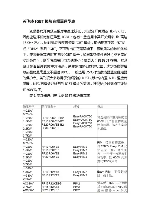
英飞凌IGBT模块变频器选型表变频器的开关频率相对来说比较低,大部分开关频率fk<8KHz,因此应选择低饱和压降型IGBT;也有一些应用中其开关频率fk 高达15KHz 左右,这时就应选择高频型IGBT模块,即选用英飞凌“KT3”或“DN2”系列IGBT。
下面列出在正常环境下,强迫风冷的散热条件下,变频器推荐选用英飞凌IGBT 型号,如果散热条件更好(或更差的冷却条件),则可考虑采用电流值更小(或更大)的IGBT模块。
检测设计是否合理的简单方法是:逆变器加热到额定功率,达到热稳定后散热器的最高温度不超过80℃,一般选用75℃作为散热器温度继电器的保护点。
英飞凌大多数用于变频器的IGBT模块均内置NTC 温度传感器,NTC 更有效地检测到IGBT模块的壳温,建议这个过温点可设计在90℃以下。
表1 变频器选用英飞凌IGBT模块推荐表凌FF450R12ME3(两单元)或FS450R12KE3(六单元),其特点是内部封装电感低,结构易于并联。
若要求更高的可靠性,可选择英飞凌大功率IGBT模块(IHM),它采用AlSiC 基版,耐热循环能力比铜基版高,反并联续流二极管(F.W.D)容量更大。
英飞凌IHM IGBT模块两单元可达到1200A, 1700V (FF1200R17KE3);一单元IGBT模块可达到3600A、1700V(FZ3600R17KE3)。
对于经整流后的直流母线电压大于750V 的电力电子设备或多电平级联方式中高压变频器可选用下列英飞凌IGBT 系列。
详细英飞凌IGBT模块产品目录可参阅:BSM75GB170DN2 34mm 两单元 75A,1700VBSM100GB170DLC 62mm 两单元 100A,1700VBSM150GB170DLC 62mm 两单元 150A,1700VFF200R17KE3 62mm 两单元 200A,1700VFF300R17KE3 62mm 两单元 300A,1700VBSM300GA170DLS 62mm 一单元 300A,1700VBSM400GA170DLS 62mm 一单元 400A,1700V注:“S”代表“DLC”+集电极引出端。
一、设计依据GB1094.11-2007电力变压器第11部分干式变压器GB/T 17468-2019电力变压器选用导则GB/T 10228-2015干式电力变压器技术参数和要求GB/T 22072-2018干式非晶合金铁心配电变压器技术参数和要求GB/T 6451-2015油浸式电力变压器技术参数和要求JBT 3837-2016 变压器类产品型号编制方法DB 37/T 5061-2016住宅小区供配电设施建设标准工业与民用供配电设计手册(第四版)山东鲁能泰山电力设备有限公司变压器选型手册二、设计原则1、变压器容量应根据计算负荷选择,变压器的长期负荷率不宜大于85%。
2、供配电系统中配电变压器宜选择Dyn11联结组别的变压器。
3、变压器台数应根据负荷特点和经济运行进行选择,当符合下列条件之一时,宜装设两台及以上变压器:1)、有大量一级或二级负荷;2)、季节性负荷变化较大;3)集中负荷较大。
4、装有两台及以上变压器的变电站,当其中任何一台变压器断开时,其余变压器的容量应满足一级负荷及二级负荷的用电。
5、对昼夜或季节性波动较大的负荷,供电变压器经技术经济比较,可采用容量不一致的变压器。
6、20、10、6kV配电变压器不宜采用有载调压变压器;但当20、10、6kV电源电压偏差不能满足要求,且用户有对电压要求严格的设备,单独设置调压装置技术不合理时,亦可采用20、10、6kV有载调压变压器。
电压波动幅度大、需频繁调节电压的配电台区宜选用有载调压变压器。
电室应选用10型及以上系列低损耗干式变压器。
10、特性变化大的负荷,可选用卷铁心或非晶合金变压器。
11、干式变压器外壳防护等级不低于IP2X。
与低压配电柜并列安装时,其外壳的防护等级不低于IP3X。
12、设置在民用建筑内的变压器,应选择干式变压器、气体绝缘变压器或非可燃性液体绝缘变压器。
13、设置在民用建筑物室外的变电所,当单台变压器油量为100kg及以上时,应有储油或挡油、排油等防火措施。
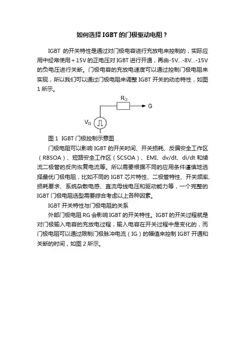
如何选择IGBT的门极驱动电阻?IGBT的开关特性是通过对门极电容进行充放电来控制的,实际应用中经常使用+15V的正电压对IGBT进行开通,再由-5V…-8V…-15V 的负电压进行关断。
门极电容的充放电速度可以通过控制门极电阻来实现,所以我们可以通过门极电阻来调整IGBT开关的动态特性,如图1所示。
图1 IGBT门极控制示意图门极电阻可以影响IGBT的开关时间、开关损耗、反偏安全工作区(RBSOA)、短路安全工作区(SCSOA)、EMI、dv/dt、di/dt和续流二极管的反向恢复电流等。
所以需要根据不同的应用条件谨慎地选择最优门极电阻,比如不同的IGBT芯片特性、二极管特性、开关频率、损耗要求、系统杂散电感、直流母线电压和驱动能力等,一个完整的IGBT门极电阻选型需要综合考虑以上各种因素。
IGBT开关特性与门极电阻的关系外部门极电阻RG会影响IGBT的开关特性。
IGBT的开关过程就是对门极输入电容的充放电过程,输入电容在开关过程中是变化的,而门极电阻可以通过限制门极脉冲电流(IG)的幅值来控制IGBT开通和关断的时间,如图2所示。
图2 IGBT开通和关断时的门极电流示意图图3 IGBT开关损耗和开关时间与门极电阻RG的关系减小门极电阻时需要考虑大电流快速开关带来的di/dt问题。
过大的di/dt会通过回路杂散电感产生很高的电压尖峰,这个尖峰电压可由公式(1)得出:这种电压尖峰可以在IGBT的关断波形中观察到,如图4所示,阴影部分的面积代表对应的开关损耗。
过大的瞬时电压尖峰叠加在IGBT 的集电极和发射极上有可能损坏IGBT,尤其是在短路工况时,大电流关断IGBT会引起很大的di/dt。
通常增大门极电阻可以减小Vstray,降低IGBT过压失效的风险。
图4 IGBT开通与关断波形在半桥拓扑中,需要在上下桥臂开关切换之间加入互锁和死区时间,这时需要考虑门极电阻对开关时间的影响。
比如较大的关断电阻RG(off)会延长IGBT的下降时间,这样实际的死区时间就有可能大于设置的最小死区时间,引起桥臂直通。
干式变压器的选型【摘要】干式变压器的选型是在工程设计过程中至关重要的一环。
本文将介绍选型的重要性以及环境条件、负载特性、容量选择、电压等级和绝缘等级对干式变压器选型的影响。
正确选型是确保设备正常运行和延长设备寿命的关键,涉及到多方面因素需要综合考虑。
在选型过程中,需要注意综合考虑环境条件、负载特性、容量选择等因素,确保干式变压器能够适应实际需求。
选型过程中,需要注意绝缘等级的确定,以保证设备在运行过程中不受损坏。
正确选型不仅能够提高设备的效率,同时也可以减少设备的维护成本和减少停机时间,从而提高设备的可靠性和稳定性。
选型是干式变压器使用过程中需要重点关注和细致考虑的环节。
【关键词】干式变压器、选型、环境条件、负载特性、容量选择、电压等级、绝缘等级、正确选型、选型过程、关键、注意问题。
1. 引言1.1 什么是干式变压器的选型干式变压器是一种常用的电力设备,主要用于将高压电能转变为低压电能或者反之。
选型是指在使用干式变压器时,根据实际情况选择合适的变压器型号和规格,以确保设备运行稳定、安全和高效。
选型的重要性不言而喻,只有正确选择合适的干式变压器才能有效地满足电力系统的需求,提高电力系统的可靠性和运行效率。
在进行干式变压器选型时,需要考虑多方面因素。
环境条件对选型有重要影响。
如果变压器所处的环境温度较高,就需要选择能够耐高温的干式变压器。
负载特性也是影响选型的重要因素。
根据实际负载情况选择合适的容量和额定功率是确保变压器正常运行的关键。
容量选择、电压等级和绝缘等级也是干式变压器选型过程中需要考虑的关键因素。
容量选择要根据实际负载需求和运行要求进行合理选择,电压等级则需根据电网的电压等级和变压器的传输功率来确定,而绝缘等级则需要根据变压器所处的环境和运行要求来确定。
1.2 选型的重要性选型是干式变压器设计过程中至关重要的一环,它直接影响到变压器在使用过程中的性能和可靠性。
正确的选型可以确保变压器在整个运行周期内正常工作,减少故障率,延长设备寿命,提高系统运行效率。