MKW1044中文资料
- 格式:pdf
- 大小:255.16 KB
- 文档页数:8
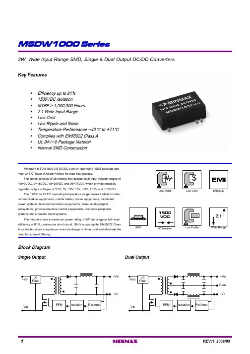
Dual OutputSingle OutputBlock DiagramMKW1000 series of DC/DC converters, comprising 24different models, is designed for a wide range of applications including data communication equipments, mobile battery driven equipments, distributed power systems, telecommunicationequipments, mixed analog/digital subsystems, process/machinecontrol equipments,computer peripheral systems and industrial robot systems.Packing up to 10W of power into a 2 x 1 x 0.4 inch package, with efficiencies as high as 83%, the MKW1000 has wide input ranges of 9-18VDC, 18-36VDC and 36-75VDC and is available in output voltages of 3.3V, 5V, 12V, 15V, 24V, {5V, {12V and {15V.Other feathers include continuous short circuit protection,six-side shielded case and EN55022 level A conducted noisecompliance minimize design-in time, cost and eliminate the need for external components.yMTBF > 700,000 Hoursy Six-Side Shielded Case y EMI Complies With EN55022 Class A y Industry Standard Pinouty Short Circuit Protection y SMT Technologyy I/O Isolation 1500VDC y 2:1 Input Rangey High Efficiency up to 83%Key FeaturesSingle and Dual Outputs10 Watts 2:1 Wide Input Range DC/DC Converters83251{17{333{15MKW104883251{21{416{12MKW104781257{50{1000{5MKW1046832512141624MKW1045832523467015MKW1044822534283012MKW10438026010020005MKW104276121021712024003.348( 36 ~ 75 )MKW104182507{17{333{15MKW103882507{21{416{12MKW103780521{50{1000{5MKW1036835012141624MKW1035825113467015MKW1034825064283012MKW10337853410020005MKW103276252043412024003.324( 18 ~ 36 )MKW1031801041{17{333{15MKW1028811027{21{416{12MKW1027781068{50{1000{5MKW10268110272141624MKW10258010473467015MKW10248010384283012MKW102377108210020005MKW102272503091712024003.312( 9 ~ 18 )MKW1021% (Typ.)mA (Typ.)mA (Typ.)mA (Typ.)mA mA VDC VDC@Max. Load @No Load @Max. Load Min.Max.EfficiencyReflected Ripple Current Input CurrentOutput CurrentOutput VoltageInput VoltageModel NumberModel Selection GuideEN55022 Class AConducted EMIFree-Air Convection Cooling%95---Humidity ]+125-40Storage Temperature ]+90-40CaseOperating Temperature ]+71-40Ambient Operating Temperature Unit Max.Min.Conditions ParameterEnvironmental SpecificationsExceeding these values can damage the module. These are not continuous operating ratings.mW5,000---Internal Power Dissipation]260---Lead Temperature (1.5mm from case for 10 Sec.)VDC 100-0.748VDC Input ModelsVDC 50-0.724VDC Input ModelsVDC 25-0.712VDC Input ModelsInput Surge Voltage( 1000 mS )Unit Max.Min.ParameterNote :1. Specifications typical at Ta=+25], resistive load,nominal input voltage, rated output current unless otherwise noted.2. Transient recovery time is measured to within 1%error band for a step change in output load of 75%to 100%.3. Ripple & Noise measurement bandwidth is 0-20MHz.4. These power converters require a minimum output loading to maintain specified regulation.5. Operation under no-load conditions will not damage these devices; however they may not meet all listed specifications.6. All DC/DC converters should be externally fused at the front end for protection.7. Other input and output voltage may be available,please contact factory.8. Specifications subject to change without notice.Absolute Maximum RatingsK Hours------700MIL-HDBK-217F @ 25], Ground BenignMTBFKHz 340300260Switching Frequency pF 470150---100KHz,1VIsolation Capacitance M[------1000500VDC Isolation Resistance VDC ------1650Flash Tested for 1 SecondsIsolation Test Voltage VDC ------150060 SecondsIsolation Voltage Unit Max.Typ.Min.Conditions ParameterGeneral SpecificationsContinuousOutput Short Circuit%/]{0.02{0.01---Temperature Coefficient %{4{2---Transient Response Deviation uS 300150---25% Load Step Change Transient Recovery Time %------120Over Power Protection mV rms.15------Ripple & Noise (20MHz)mV P-P 100------Over Line,Load & Temp Ripple & Noise (20MHz)mV P-P 7550---Ripple & Noise (20MHz)%{0.5{0.1---Io=10% to 100%Load Regulation %{0.3{0.1---Vin=Min. to Max.Line Regulation %{2.0{0.5---Dual Output Balance LoadOutput Voltage Balance %{1.0{0.5---Output Voltage Accuracy Unit Max.Typ.Min.ConditionsParameterOutput SpecificationsPi FilterInput FiltermW 45003500---Short Circuit Input Power A 2------All ModelsReverse Polarity Input Current 34292548V Input Models17151324V Input Models 8.58712V Input Models Under Voltage Shortdown36333048V Input Models18171524V Input Models VDC 98.5812V Input Models Start VoltageUnitMax.Typ.Min.Model ParameterInput SpecificationsNote: # For each output .uF47047047022002200220022002200Maximum Capacitive Load Unit {15V #{12V #{5V #24V 15V 12V 5V 3.3V Models by Vout Capacitive Load750mA Slow - Blow Type1500mA Slow - Blow Type3000mA Slow - Blow Type48V Input Models 24V Input Models 12V Input Models Input Fuse Selection GuideInput Voltage Transient RatingTest ConfigurationsInput Reflected-Ripple Current Test SetupLin (4.7uH) and Cin (220uF, ESR < 1.0[ at 100 KHz) to simulate source impedance.Capacitor Cin, offsets possible battery impedance.Current ripple is measured at the input terminals of the module, measurement bandwidth is 0-500 KHz.Peak-to-Peak Output Noise Measurement TestUse a Cout 0.47uF ceramic capacitor.Scope measurement should be made by using a BNC socket, measurement bandwidth is 0-20 MHz. Position the load between 50 mm and 75 mm from the DC/DC Converter.Design & Feature ConsiderationsMaximum Capacitive LoadThe MKW1000 series has limitation of maximum connected capacitance at the output.The power module may be operated in current limiting mode during start-up, affecting the ramp-up and the startup time.For optimum performance we recommend 470uF maximum capacitive load for dual outputs and 2200u F capacitive load for single outputs.The maximum capacitance can be found in the data .Overcurrent ProtectionTo provide protection in a fault (output overload) condition,the unit is equipped with internal current limiting circuitry and can endure current limiting for an unlimited duration. At the point of current-limit inception, the unit shifts from voltage control to current control. The unit operates normally once the output current is brought back into its specified range.Input Source ImpedanceThe power module should be connected to a low ac-impedance input source. Highly inductive source impedances can affect the stability of the power module.In applications where power is supplied over long lines and output loading is high, it may be necessary to use a capacitor at the input to ensure startup.Capacitor mounted close to the power module helps ensure stability of the unit, it is recommended to use a good quality low Equivalent Series Resistance (ESR < 1.0[ at 100KHz) capacitor of a 15uF for the 12V input devices and a 4.7uF for the 24V and 48V devices.A good quality low ESR capacitor placed as close as practicable across the load will give the best ripple and noise performance.To reduce output ripple, it is recommended to use 3.9uF capacitors at the output.Thermal ConsiderationsMany conditions affect the thermal performance of the power module, such as orientation, airflow over the module and board spacing. To avoid exceeding the maximum temperature rating of the components inside the power module, the case temperature must be kept below 90°C.The derating curves are determined from measurements obtained in an experimental apparatus.Units are encapsulated in a low thermal resistance molding compound which has excellent chemical resistance and electrical properties in high humidity environment and over a wide operating temperature range.The encapsulant and outer shell of the unit have UL94V-0 ratings. The leads are golden plated for better soldering.UL94V-0:Flammability32g :Weight-Vout-Vout5Common No Pin 4Metal With Non-Conductive Baseplate :Case Material +Vout +Vout 3-Vin -Vin 2 2.0*1.0*0.4 inches+Vin +Vin 150.8*25.4*10.2 mm :Case Size Dual OutputSingle OutputPin Physical CharacteristicsPin Connections{0.002{0.05PinConnecting Pin PatternsTop View ( 2.54 mm / 0.1 inch grids )Mechanical Data。