PELCO-D控制协议
- 格式:doc
- 大小:32.00 KB
- 文档页数:2
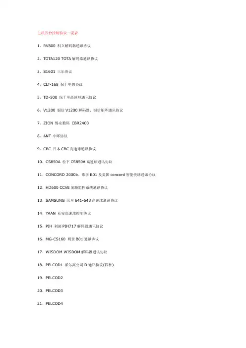
主机云台控制协议一览表1、RV800 科立解码器通讯协议2、TOTA120 TOTA解码器通讯协议3、S1601 三乐协议4、CLT-168 保千里的协议5、TD-500 保千里高速球通讯协议6、V1200 银信V1200解码器、银信矩阵通讯协议7、ZION 锡安数码CBR24008、ANT 中晖协议9、CBC 日本CBC高速球通讯协议10、CS850A 松下CS850A高速球通讯协议11、CONCORD 2000b、维多B01及美国concord智能快球通讯协议12、HD600 CCVE闭路监控系统通讯协议13、SAMSUNG 三星641-643高速球通讯协议14、YAAN 亚安高速球控制协议15、PIH 利凌PIH717解码器通讯协议16、MG-CS160 明景B01通讯协议17、WISDOM WISDOM解码器通讯协议18、PELCOD1 派尔高公司D通讯协议(四种)19、PELCOD220、PELCOD321、PELCOD422、PELCOP1 派尔高公司P通讯协议(三种)23、PELCOP224、PELCOP325、philips 飞利浦高速球通讯协议(需要485-曼码转换器)26、NEOCOM 耐康姆协议27、名称未定新增加振华重大协议协议预制、是否支持是否有协议预制、是否支持是否有调用高速球自动功能调用高速球自动功能Philips 有支持没有CONCORD 有不支持有PELCOP3 有不支持有CS850A 有支持有PELCOP2 有不支持有CBC 有支持有PELCOP1 无不支持有ANT 无不支持有PELCOD4 有不支持有ZOIN 有不支持有PELCOD3 有不支持有V1200 有不支持有PELCOD2 有不支持有TD-500 有不支持有PELCOD1 无不支持有CLT-168 无不支持有WISDOM 无不支持有S1601MG-CS160 有支持有TOTA120 无不支持有PIH 有不支持有RV800 无不支持有YAAN 有支持有NEOCAM 无不支持有SAMSUNG 有支持有ZHZD 无不支持有HD600 有不支持有云台协议信息请注意: PELCO协议的自动码很有可能不同,基本上一个厂家一个定义,所以有自动功能并不能说明自动能控制,只有和我们协议相符合才能控制.云台控制原理DVR通过与解码器(或球机)的通讯控制云台DVR--------à解码器/球机————―――>摄像头DVR通过485信号向解码器球机发送命令,解码器/球机通过各种方式控制摄像头协议是DVR与解码器通讯的协议,DVR为发送命令方,解码器、球机接收,双方的协议相同才能控制.常见问题1如出现继电器响但是聚焦不成功等问题问题出在解码器(或球机)与摄像头的控制,请客户与解码器(或球机)的厂商联系.2如果协议对上但是继电器不响,可以变换地址码(加1或减1)进行控制.3如果方向可以控制,但是不能控制预制调用或自动,如果继电器没有响,那么就是我们的协议不同,不支持客户的解码器.。
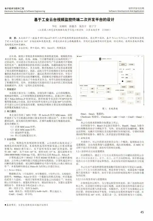
电子技术与软件工程Electronic Technology & Software Engineering软件开发与应用Software Development And Application基于工业云台视频监控终端二次开发平台的设计华壮侯杨阳陈敏杰朱浩宇钮宁宁(江苏第二师范学院物理与电子信息工程学院江苏省南京市210000 )摘要:本文设计了一款基于M F C+OpenCV的可二次开发的视频监控终端系统,通过串口通讯,基于Pelco-D/Pelco-P控制协议实现 了对工业变速云台360。
方向控制和角度设置;并通过在云台上搭栽摄像头,实现对监控场景的实时监测。
经过调试,表明本系统具有较 高的稳定性和实操性。
关键词:云台控制;串口通讯;M F C;OpenCV;视频监控近年来,随着计算机技术和网络技术的快速发展,视频监控技 术在停车场、地跌、机场、商城、写字楼等重要公共场所得到了广 泛的运用,可以说各行各业以及人们的日常生产生活都离不开视频 监控技术[11。
随着视频监控技术的日益成熟,也越来越成为计算机 视觉研究领域中的热点。
各大高校、教育机构应人才培养需求设置 了相关课程和课题设计,因此,高校大学生在校期间非常有必要接 触到此类此类项目的开发设计,通过此类项目的教学实训,不仅可 以提高学生对所学知识的理解程度,更能够充分锻炼动手实践操作 能力,很大程度上提高了专业技术竞争力,对学生的职业规划起到 了积极的作用。
另外,该系统也可直接应用于企业中的工程应用或 实验测试中,具有一定的社会实用价值。
1系统设计该系统主要分为三大模块,分别为串口通讯、云台控制模块、视频监控模块。
云台控制模块是视频监控的核心,是通过串口通汛,基于Pelco-D/Pelco-P控制协议,将控制指令发送给FY-SP15丨0轻 载智能变速云台设备,设计对应控件实现对云台设备360°方向控制,并可进行云台任意角度的设置;视频监控模块主要实现对搭载相机 的图像采集捕捉与显示。
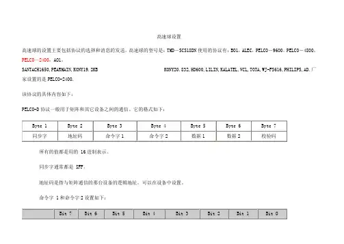
高速球设置高速球的设置主要包括协议的选择和消息的发送。
高速球的型号是:TMD-SCS18DN使用的协议有:BO1,ALEC,PELCO-9600,PELCO-4800,PELCO-2400,AO1,SANTACH1650,PEARMAIN,KONY19.2KB KONY20.832,HD600,LILIN,KALATEL,VCL,TOTA,WJ-FS616,PHILIPS,AD.厂家设置的是PELCO-2400.该协议的具体内容如下:PELCO-D协议一般用于矩阵和其它设备之间的通信。
它的格式如下:所有的值都是用的 16进制表示。
同步字通常都是 $FF。
地址码是指与矩阵通信的那台设备的逻辑地址,可以在设备中设置。
命令字 1和命令字2设置如下:Sence码与Bit4和Bit3有关。
在Bit4和Bit3为1的情况下,如果Sence码为1,则命令就是自动扫描和和摄像机打开;如果Sence 码为0,则命令就是手动扫描和摄像机关闭。
当然如果Bit4或Bit3为0的话那命令就无效了。
数据1表示镜头左右平移的速度,数值从$00(停止)到$3F(高速),另外还有一个值是$FF,表示最高速。
数据2表示镜头上下移动的速度,数值从$00(停止)到$3F(最高速)。
校验码是指Byte2到Byte6这5个数的和(若超过255则除以256然后取余数)。
PELCO-P协议PELCO-P协议一般采用RS-485传输,波特率为4800,1位起始位和停止位,8位数据位,无校验。
其格式如下:起始码是固定值$A0。
地址码是设备的逻辑地址,可由接收设备上的DIP开关来设定。
数据位1到4的意义如下:停止码是固定值 $AF 。
校验码是 Byte2 到 Byte6 这 5 个数的异或值(XOR)。
地址码是从 0编起的,所以地址码$00表示第一台设备。
PELCO-D和PELCO-P协议另有一些特殊命令,可对设备进行一些高级控制,EXTENDED COMMANDS:In addition to the “PTZ” commands shown above, there are control commands that allow you access to the more advanced features of some equipment. The response to one of these commands is four bytes long. The first byte is the synchronization character (FF), the second byte is the receiver address, the third byte contains the alarm information and the fourth byteis the check sum.PTZ命令控制说明:⒈当控制云台水平、上下方向动作或“IRIS”、“FOCUS”、“ZOOM”时需要使相应的控制位为“1”,不用控制的相应位置为“0”⒉当需要云台PAN/TILT两方向同时动作时,只需将PAN/TILT的相应控制位置“1”即可,PAN/TILT 的速度控制由WORD5/WORD6决定⒊将WORD3、WORD4的所有位置为“0”可以停止云台的动作5、扩充命令。

智能安防网络高清监控系统解决方案PELCO CCTVPELCO近年国内重点项目北京市委、市政府安防系统北京钓鱼台国宾馆监控二期毛主席纪念堂监控系统国航飞行员公寓安防国家体育馆训练总局监控系统某军区监控系统中南海电话局监控系统北京市公安局疗养院监控系统北京会议中心监控系统大兴区政府办公楼监控系统海淀区政府办公楼监控系统山东青岛城市道路监控系统山东烟台城市道路监控山东临沂电厂监控系统山东泰安煤矿监控系统山东泰山风景区监控系统山东威海城市道路监控山东潍坊火车站监控系统山东诸城道路监控系统青藏铁路监控系统内蒙满州里城市道路监控呼和浩特白塔机场监控系统鄂尔多斯城市道路监控系统辽宁锦州城市道路监控辽宁沈阳城市道路监控辽宁白山道路监控系统大连城市道路监控系统大连机场监控系统大连市中国银行办公楼监控系统大连港30万吨矿石码头大庆油田北油库河北衡水城市道路监控河北沧州城市道路监控系统京唐港港口监控系统河北邯郸城市道路监控系统浙江萧山杭州第二邮政枢纽浙江义乌市城市监控系统浙江温岭市道路监控系统浙江湖州道路监控系统江苏盐城供电局无人变电站上海沪闵高架江苏张家港市道路监控系统南京森林公安学校杭州公安局治安动态监控系统广西北海经济开发区江西宜春市公安局市区治安监控山西太原市道路陕西神木县公安局监控系统浙江温岭城市道路深圳福田区供电局无锡城市道路山西太原电厂上海F1赛车场赛道图像监控上海外高桥港区、物流园区上海沪嘉、沪青平高速公路上海印钞厂监控系统上海176号市政项目上海南浦、杨浦、卢浦大桥上海东海大桥监控系统上海漕河泾海关出口加工区上海联想大厦上海青浦海关出口加工上海银辰数码大厦上海九百城市广场购物中心上海市嘉定区政府办公中心上海西郊购物中心安防上海市公安局综合指挥大楼监控系统上海大连路、复兴路过江隧道上海内环高架路上海洋山港监控系统上海浦东机场监控系统南通市新政府大楼天津保税区仓库天津泰达大厦监控系统西安航空大厦长庆石油探测基地监控系统阳光商东酒店监控系统中国移动公司办公楼监控系统山东国泰化工厂监控系统青岛中级法院办公楼监控系统烟台芝罘区法院办公楼监控系统山东潍坊市公安局监控系统海南博鳌亚洲论坛监控系统深圳宝安机场监控系统乌鲁木齐市公安局办公楼监控系统乌鲁木齐高速路监控系统独山子体育馆监控系统宁夏银川石中高速公路西宁城市道路监控系统昆明巫家坝机场监控系统四川泸州市城市道路监控系统成都双流机场监控系统贵州乌江渡水电站监控系统北京体育大学监控系统首都经贸大学监控系统京西学校监控系统北师大附属实验中学监控系统BDA实验学校监控系统中国传媒大学校区安防系统首都医科大学监控系统首都师范大学监控系统北京科技大学校区监控系统北京理工大学校区安防系统北京工商大学校区安防系统北京外国语大学监控系统北京对外经贸大学监控系统中央美术学院校区监控系统奥体中心监控系统地坛体育馆监控系统电子工业出版社监控系统金融街地下车库监控系统北京国际楼宇监控系统观湖国际监控系统洛克时代中心监控系统富盛大厦监控系统中海凯旋大厦监控系统昌平区检察院新办公路监控系统北京地铁十号线监控系统东直门公交枢纽监控系统齐家园外交公寓监控系统塔园外交公寓监控系统中央电视塔监控系统302医院监控系统后勤指挥学院监控系统北京邮电大学监控系统北京科技大学监控系统上海水务局长宁服务综合楼乐成中心,乐成豪庭监控系统马哥孛罗酒店监控系统用友办公楼监控系统江苏南通市新市政综合办公中心江苏第二少管所目录1 概述 (10)1.1 项目背景和建设目标 (10)1.2 网络视频监控技术概述 (10)1.2.1 视频监控技术的演变 (10)1.2.2 网络化视频监控 (12)2 需求分析 (12)2.1 前端监控点位建设 (12)2.2 系统功能需求 (13)2.3 录像存储需求 (16)2.4 网络现状与规划 (16)3 设计依据 (16)4 设计原则 (17)5 系统设计方案 (19)5.1 系统总体结构图 (19)5.2 视频采集............................................................................................................ - 21 -5.2.1 PELCO网络摄像机的特点和优势 .......................................................... - 21 -5.2.2 前端摄像机选型........................................................................................ - 25 -5.3 网络传输............................................................................................................ - 25 -5.3.1 CVBR带宽管理策略................................................................................ - 25 -5.3.2 组播技术.................................................................................................... - 26 -5.3.3 带宽计算.................................................................................................... - 27 -5.4 录像与视频管理服务........................................................................................ - 28 -5.4.1 图像存储空间配置.................................................................................... - 28 -5.4.2 录像与视频管理........................................................................................ - 29 -5.4.3 Endura Stor存储延长技术........................................................................ - 35 -5.5 监控中心设计.................................................................................................... - 36 -5.5.1 视频控制显示台........................................................................................ - 37 -5.5.2 高清视频解码器........................................................................................ - 38 -5.5.3 Endura View技术...................................................................................... - 39 -5.5.4 工作站........................................................................................................ - 41 -5.5.5 系统管理器................................................................................................ - 44 -5.6 系统功能............................................................................................................ - 45 -6 技术培训............................................................................................................................ - 52 -7 售后服务............................................................................................................................ - 54 -PELCO CCTV-北京中科软件有限公司1概述1.1项目背景和建设目标XX网络高清智能安防监控系统1.2网络视频监控技术概述1.2.1视频监控技术的演变时至今日,业内普遍认为视频监控系统已经发展到第三代。
码器适用协议
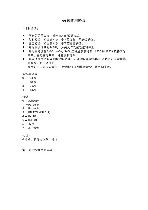
1控制协议;
●所有的适用协议,都为RS485数据格式。
●加和校验:初始值为0,按字节加和,不进位的值。
●异或校验:初始值为0,按字节异或的值。
●解码器收到其他命令时,原先为自动的功能将停止;
●解码器可设置2400,4800,9600三种通信波特率,1200和19200波特率为
系统设置是否为其中一种通信波特率。
●除自动模式功能以外的功能命令,云台功能命令如果在30秒内没有收到停
止命令,将自动停止。
镜头方面的命令如果在10秒内没有收到停止命令,将自动停止。
波特率设置:
0 -- 2400
1 -- 4800
2 -- 9600
3 – 19200
协议:
0 -ADR8060
1 -Pelco D
2 –Pelco P
3 - KALATEL(KTP312)
4 – RM110
5 – KRE301
6 –备用
7 – ADT8060
地址:
0开始,有的协议从1开始;
如下为支持协议的资料:
名称:ADR8060 或CCR-20G
编号:1
波特率:2400,4800,9600,
数据类型:HEX
命令连续重复发送,间隔时间小于200ms。
二种情况动作会停止:a)命令间隔超过250ms,b)收到停止命令。
名称:PELCO-D
编号:2
波特率:2400,4800,9600,数据类型:HEX
名称:PELCO-P
编号:3
波特率:2400,4800,9600,数据类型:HEX
0地址代表1地址,以此类推;。

PELCO协议协议名称:PELCO协议一、引言本协议旨在规范PELCO协议的标准格式,确保各方在使用PELCO协议时能够准确理解和遵守相关规定。
二、定义1. PELCO协议:指由PELCO公司开发的一种用于视频监控设备之间通信的协议。
2. 发送方:指发送PELCO协议命令的设备或系统。
3. 接收方:指接收并执行PELCO协议命令的设备或系统。
三、通信协议1. 数据格式:PELCO协议使用二进制格式进行通信。
2. 命令结构:PELCO协议命令由固定长度的字段组成,包括起始码、地址码、命令码、数据1、数据2和校验码。
a) 起始码:占用1个字节,用于标识命令的开始。
b) 地址码:占用1个字节,用于指定接收方的地址。
c) 命令码:占用1个字节,用于指定具体的命令类型。
d) 数据1和数据2:占用各1个字节,用于传输附加数据。
e) 校验码:占用1个字节,用于验证命令的正确性。
3. 命令类型:PELCO协议定义了一系列命令类型,包括镜头控制、云台控制、预置位设置等。
具体命令类型详见PELCO协议文档。
四、命令规范1. 镜头控制命令:用于控制摄像头的焦距、光圈等参数。
a) 命令码:0x00至0x03。
b) 数据1:用于指定具体的操作,如焦距调整、光圈调整等。
c) 数据2:用于传输附加数据,如焦距变化的步长。
2. 云台控制命令:用于控制摄像头的云台运动。
a) 命令码:0x04至0x07。
b) 数据1:用于指定具体的操作,如云台转动、云台停止等。
c) 数据2:用于传输附加数据,如云台转动的速度。
3. 预置位设置命令:用于设置和调用预置位。
a) 命令码:0x08至0x0B。
b) 数据1:用于指定具体的操作,如设置预置位、调用预置位等。
c) 数据2:用于传输附加数据,如预置位的编号。
4. 其他命令:PELCO协议还定义了其他类型的命令,如亮度调整、对比度调整等。
具体命令类型详见PELCO协议文档。
五、通信流程1. 发送方向接收方发送PELCO协议命令。

内置解码板说明中文版普通解码板一、主要参数:1、RS485通讯,最远1200m2、多种控制协议(内含18个协议,其它协议请与供应商联系)3、体积:110×80×14mm4、适合安装到7寸以上的室内外球机5、AC24V供电,适用于AC24V的球形云台6、内置10W开关模块电源,可提供DC12V/500mA稳压电源给摄像机供电7、可控制三可变镜头、全方位云台二、协议设置:4位拨码开关注:KODICOM和PIACSO卡增加了控制光圈功能。
三、KODICOM RX和KRE-301RX协议中光圈控制方法(该协议地址编码为10进制编码)在PICASO录像卡和KODICOM的录像卡的软件中没有光圈控制功能,在本解码器中针对这两种软件增加了控制光圈功能。
●KODICOM硬盘录像机中选KRE-301RX协议。
控制光圈时,先把雨刷开关打开,然后控制聚焦控制按钮,即可控制光圈,控制完成后,把雨刷开关关掉。
●在PICASO的硬盘录像机中选KODICOM RX协议。
控制光圈时,先把电源开关打开,然后控制聚焦控制按钮,即可控制光圈,控制完成后,把电源开关关掉。
注:以上两种软件波特率选择9600KODICOM/KRE-301中十进制地址码开关设置普通球机内置解码板接线图预置位解码板一、功能特点:1、接普通云台可实现128个预置点的精确定位2、采用电机信号检测技术,彻底解决多次转动后定位不准的缺陷3、1条可编程自动巡视线(预置点1-10循环调用),即按轨迹巡视,巡视停留时间5秒,该功能将取代云台的自动功能4、位置精度:小于1度5、累计偏差:自动巡视时,小于2度/24小时6、可控制三可变镜头、全向云台和一组辅助开关(选配)7、内含PELCO-D、PELCO-P协议,其它协议可以追加,波特率1200、2400、4800、9600可选8、RS485通讯,通讯距离最远可达1200m,防静电、抗雷击9、交流24V供电,集成10W开关模块电源,提供DC12V-500mA摄像机电源10、采用智能电源管理技术,可实现电源功率自动分配,如果某个供电设备电源功耗较低、它会把功率自动转给其它供电设备11、采用模块技术,体积小、功能强、质量可靠、安装方便二、预置点的工作过程和使用方法:a)通电后解码器进行自检(转到右下方),然后立即回到第一个预置点(需预先设置预置点)。
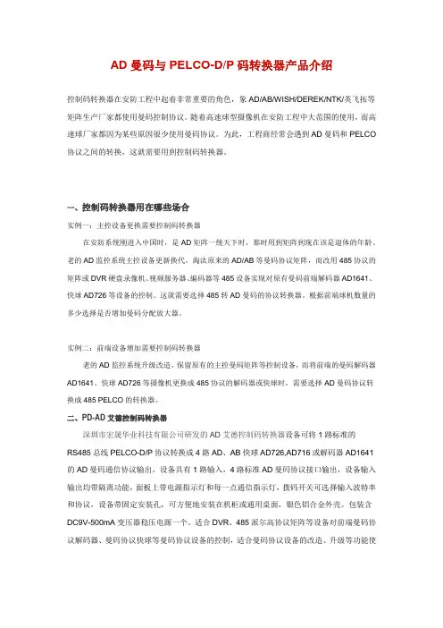
AD曼码与PELCO-D/P码转换器产品介绍控制码转换器在安防工程中起着非常重要的角色,象AD/AB/WISH/DEREK/NTK/英飞拓等矩阵生产厂家都使用曼码控制协议。
随着高速球型摄像机在安防工程中大范围的使用,而高速球厂家都因为某些原因很少使用曼码协议。
为此,工程商经常会遇到AD曼码和PELCO 协议之间的转换,这就需要用到控制码转换器。
一、控制码转换器用在哪些场合实例一:主控设备更换需要控制码转换器在安防系统刚进入中国时,是AD矩阵一统天下时,那时用到矩阵到现在该是退体的年龄。
老的AD监控系统主控设备更新换代,淘汰原来的AD/AB等曼码协议矩阵,而改用485协议的矩阵或DVR硬盘录像机、视频服务器、编码器等485设备实现对原有曼码前端解码器AD1641、快球AD726等设备的控制。
这就需要选择485转AD曼码的协议转换器。
根据前端球机数量的多少选择是否增加曼码分配放大器。
实例二:前端设备增加需要控制码转换器老的AD监控系统升级改造,保留原有的主控曼码矩阵等控制设备,而将前端的曼码解码器AD1641、快球AD726等摄像机更换成485协议的解码器或快球时,需要选择AD曼码协议转换成485 PELCO的转换器。
二、PD-AD艾德控制码转换器深圳市宏晟华业科技有限公司研发的AD艾德控制码转换器设备可将1路标准的RS485总线PELCO-D/P协议转换成4路AD、AB快球AD726,AD716或解码器AD1641的AD曼码通信协议输出,设备具有1路输入,4路标准AD曼码协议接口输出,设备输入输出均带隔离功能,面板上带电源指示灯和每一点通信指示灯,拨码开关可选择输入波特率和协议,设备带固定安装孔,可方便地安装在机柜或通用桌面,银色铝合金外壳。
包装含DC9V-500mA变压器稳压电源一个。
适合DVR、485派尔高协议矩阵等设备对前端曼码协议解码器、曼码协议快球等曼码协议设备的控制,适合曼码协议设备的改造、升级等功能使用,解决AD或AB矩阵系统搭配问题。
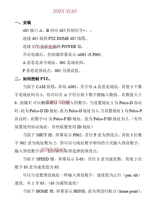
一、安装485接口A、B对应485控制信号+、-.连接485端到PTZ DOME 485线缆。
连接12V直流电源到POWER端。
开启电源后,控制器屏幕显示A001或P001.A意思是命令地址,001是地址码。
P意思是预设点,001为预设值。
二、如何控制PTZ。
当按下CAM按钮,屏显A001,首字母A意思是地址,其他3个数字是地址码为1,你可以在A字符后按下数字键输入数值。
若数值大于9,按键C可以删除最后一位输入的数字,当设置地址1为Pelco-D协议时,此为Pelco-D ID地址,意为Pelco-D地址为1,当设置地址1为Pelco-P 协议时,此数字+1为Pelco-P ID地址,意为Pelco-P ID地址为2。
(有些装置使用协议地址,有些装置使用ID地址)当按下SHUT键,屏幕显示P002。
首位P意为预设点,其他3位数字002意为地址数为2,你可以与地址数字相同的方式输入预设数字。
输入预设数字后,监控探头取得选择的预设点。
当按下SPEED键,屏幕显示S-63,首位S意为速度数,其他2位数字63意为速度值为63.可以与设置预设地址一样输入预设数字,速度值为云台(pan tilt)速度,从1至63。
(63为最快速度)当按下HOME键,屏幕显示HONE,意为预设归航点(home point),可以使用PRESET(预设),DELELT(应为DELETE删除)设置或者清除该点。
当按下A或B键,屏幕显示LT-A或LT-B,意为预设限制点A或限制点B,可以作为自动模式的左止点或右止点。
可以利用PRESET,DELETE设置或者清除该点。
当按下PRESET键3秒钟,屏幕显示SET-,意为预设模式,若需要设置一个预设值,需要按下PRESET键3秒,控制器显示SET-,此时可以输入一个数字(此时也可按下HOME A B键设置起始点与左右限制点),若须输入一个大于10的数字,可以首先按下-/--键。
输入数字后,须按ENTER键确认。
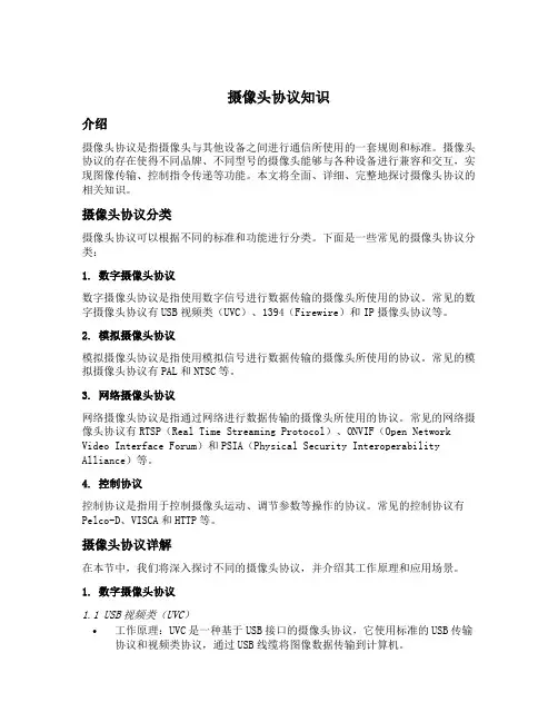
摄像头协议知识介绍摄像头协议是指摄像头与其他设备之间进行通信所使用的一套规则和标准。
摄像头协议的存在使得不同品牌、不同型号的摄像头能够与各种设备进行兼容和交互,实现图像传输、控制指令传递等功能。
本文将全面、详细、完整地探讨摄像头协议的相关知识。
摄像头协议分类摄像头协议可以根据不同的标准和功能进行分类。
下面是一些常见的摄像头协议分类:1. 数字摄像头协议数字摄像头协议是指使用数字信号进行数据传输的摄像头所使用的协议。
常见的数字摄像头协议有USB视频类(UVC)、1394(Firewire)和IP摄像头协议等。
2. 模拟摄像头协议模拟摄像头协议是指使用模拟信号进行数据传输的摄像头所使用的协议。
常见的模拟摄像头协议有PAL和NTSC等。
3. 网络摄像头协议网络摄像头协议是指通过网络进行数据传输的摄像头所使用的协议。
常见的网络摄像头协议有RTSP(Real Time Streaming Protocol)、ONVIF(Open Network Video Interface Forum)和PSIA(Physical Security Interoperability Alliance)等。
4. 控制协议控制协议是指用于控制摄像头运动、调节参数等操作的协议。
常见的控制协议有Pelco-D、VISCA和HTTP等。
摄像头协议详解在本节中,我们将深入探讨不同的摄像头协议,并介绍其工作原理和应用场景。
1. 数字摄像头协议1.1 USB视频类(UVC)•工作原理:UVC是一种基于USB接口的摄像头协议,它使用标准的USB传输协议和视频类协议,通过USB线缆将图像数据传输到计算机。
•应用场景:UVC协议广泛应用于计算机摄像头、笔记本摄像头和一些消费类电子产品中。
1.2 1394(Firewire)•工作原理:1394协议,也被称为Firewire协议,是一种高速串行总线协议,可用于传输视频和音频数据。
它使用IEEE 1394接口将图像数据传输到计算机。
竭诚为您提供优质文档/双击可除云台通讯协议篇一:几种云台控制协议pelco产品协议解析pelco(派尔高)的监控器材在我国有很广泛的应用。
pelco有自己的传输控制协议,当它的产品配套使用时,可以互相兼容。
但在某些情况下,由于工程的需要,要求用其它设备(比如电脑)来控制pelco的矩阵或镜头,这就要求充分了解pelco的传输协议。
诶诺基数码科技有限公司的视频解码软件可完全兼容pelco协议,可通过pc机控制pelco的各种设备。
本文为你详细解析pelco常用协议之一:pelco-d协议pelco-d协议pelco-d协议一般用于矩阵和其它设备之间的通信。
它的格式如下:所有的值都是用的16进制表示。
同步字通常都是$FF。
地址码是指与矩阵通信的那台设备的逻辑地址,可以在设备中设置。
命令字1和命令字2设置如下:sence码与bit4和bit3有关。
在bit4和bit3为1的情况下,如果sence码为1,则命令就是自动扫描和和摄像机打开;如果sence码为0,则命令就是手动扫描和摄像机关闭。
当然如果bit4或bit3为0的话那命令就无效了。
数据1表示镜头左右平移的速度,数值从$00(停止)到$3F(高速),另外还有一个值是$FF,表示最高速。
数据2表示镜头上下移动的速度,数值从$00(停止)到$3F(最高速)。
校验码是指byte2到byte6这5个数的和(若超过255则除以256然后取余数)。
pelco-d&pelco-p协议格式高速球的设置主要包括协议的选择和消息的发送。
高速球的型号是:tmd-scs18dn使用的协议有:bo1,alec,pelco -9600,pelco-4800,pelco-2400,ao1,santach1650,peaRmain,kony19.2kbkony20.832,hd600,lil in,kalatel,Vcl,tota,wj-Fs616,philips,ad.厂家设置的是pelco-2400.该协议的具体内容如下:pelco-d协议一般用于矩阵和其它设备之间的通信。
云台地址码、波特率、协议拨码设置说明。
恒速球地址、协议、波特率等设置恒速球内置解码板,通过解码板对地址、协议、波特率的设置,实现对恒速球的云台和摄像机的镜头控制。
1、地址设置8位拨码开关(见下图)的1-6位用于恒速球的地址码设置,可在1~63范围内进行地址编码,每个恒速球的地址码应与硬盘录像机或矩阵或控制键盘的地址码一致,才能实现控制。
用于设置地址码6位拨码开关采用2进制,每位拨至ON时值为1,拨至OFF时值为0,详见表2。
表2:地址编码与拨码开关对应表KODICOM卡硬盘录像机KRE-301协议,上海诚丰硬盘录像机PRLCO-D,RM110协议地址采用16进制,与其它地址采用十进制不同,故地址首先需转换为十进制,拔码开关如表3表3:16进制地址与拨码开关对应表请按自己定义好的恒速球地址,按照表2或表3完成拨码开关的设置。
2、波特率设置8位拨码开关(见上图)的7、8位用于恒速球的地址码设置,可设置的波特率为1200BPS、2400BPS、480 0BPS、9600BPS。
每位拨至ON时值为1,拨至OFF时值为0,波特率与拨码开关对应见表4。
表4:波特率与拨码开关对应表请根据控制恒速球设备所采用的通信波特率按照表4完成拨码开关的设置。
3、协议设置6位拨码开关的1,2,3,4位(见上图)用于设置协议类型,内置解码板提供下表5所列的协议,也可按用户要求将其它写入其它的协议。
表5:拨码开关与协议对应表本解码器通常提供以上14种协议,但可根据用户需要提供更多协议。
可提供协议有:与矩阵通讯协议: SAMSUNG、AD、AB、达拉斯、红苹果、科力矩阵、天大天财矩阵、派尔高矩阵、银信矩阵、LP矩阵。
与硬盘录像机通讯协议:录林王嵌入式、凯创嵌入式、DM嵌入式、海康威视嵌入式、KCL(三洋)、YAAN、SAMSUNG、 KIDICOM-SX硬盘录像机使用协议与波特率参照表见表6。
与键盘通讯协议:维多键盘、PWT键盘、三星键盘、YAAN 。
Standard Number TF-0002Version1Revision1Release Date July 7, 2003 Key words: D protocol, serial, extended, Sync byte, 0xFF, Advanced Feature Set, Extended ResponseP ELCO “D” P ROTOCOLM ANUALT ABLE OF C ONTENTSDOCUMENT HISTORY (3)LEGAL NOTICES (4)N OTICE OF D ISCLAIMER (4)P ROPRIETARY N OTICE (4)Q UESTIONS (4)WHAT THIS MANUAL COVERS (5)THE BYTE FORMAT (5)THE MESSAGE FORMAT (5)The Standard Command Set (6)Extended Commands (7)Advanced Feature Set (8)Creating Labels (9)E XAMPLE M ESSAGES (9)Responses (10)Opcode Descriptions (11)APPENDIX A (17)A DVANCED F EATURE C OMMANDS (17)INDEX (19)Document History1.Initial Release, 7/07/03L EGAL N OTICESN OTICE OF D ISCLAIMERPelco makes no claims, expressed or implied, regarding the usefulness of this protocol, it’s implementation, or it’s correctness. Any use of this protocol is the sole responsibility of the agency implementing the protocol. The contents of this document and the function of the protocol are subject to change without notice.P ROPRIETARY N OTICEThe contents of this document are considered to be the property of Pelco. Users of this protocol agree to use the protocol only in the interests of Pelco. Any use of this protocol to Pelco’s detriment is prohibited.Those receiving this protocol cannot redistribute the protocol without the expressed written consent of Pelco.Q UESTIONSQuestions regarding this protocol, it’s implementation, use, and distribution should be addressed to:Pelco(559) 292-1981 Voice3500 Pelco Way(559) 292-1018 FAXClovis, California, USA 93612-5699W HAT THIS MANUAL COVERSThis manual describes the minimum requirements for implementing the Pelco “D” protocol. This protocol is used to communicate between a controlling device (e.g. a matrix switching system) and a receiver/driver (e.g. a dome drive).Not all devices will be able to accommodate all of the features available in this protocol. This protocol is designed to cover the feature sets of a wide variety of equipment.T HE B YTE F ORMATTransmitters will format a single character and receivers will be able to decipher a single characteras: 1 start bit, 8 data bits, 1 stop bit, and no parity.T HE M ESSAGE F ORMATThe format for a message is:Byte 1Byte 2Byte 3Byte 4Byte 5Byte 6Byte 7Sync Byte Address Command 1Command 2Data 1Data 2ChecksumNote that values in this document prefixed with “0x” are hexadecimal numbers.The synchronization byte (Sync Byte) is always0xFF.The Address is the logical address of the receiver/driver device being controlled.The Checksum is calculated by performing the 8 bit (modulo 256) sum of the payload bytes (bytes 2 through 6) in the message.T HE S TANDARD C OMMAND S ETCommand 1 and 2 are represented as follows:Bit 7Bit 6Bit 5Bit 4Bit 3Bit 2Bit 1Bit 0Command 1Sense Reserved ReservedAuto /ManualScanCameraOn / OffIrisCloseIrisOpenFocusNearCommand 2FocusFarZoomWideZoomTeleDown Up Left Right Always 0A value of ‘1’ entered in the bit location for the function desired will enable that function. A value of ‘0’entered in the same bit location will disable or ‘stop’ the function.The sense bit (command 1 bit 7) indicates the meaning of bits 4 and 3. If the sense bit is on (value of ‘1’), and bits 4 and 3 are on, the command will enable auto-scan and turn the camera on. If the sense bit is off (value of ‘0’), and bits 4 and 3 are on the command will enable manual scan and turn the camera off. Of course, if either bit 4 or bit 3 are off then no action will be taken for those features.The reserved bits (6 and 5) should be set to 0.Byte 5 contains the pan speed. Pan speed is in the range of ‘0x00’ to ‘0x3F’ (high speed) and ‘0x40’ for “turbo” speed. Turbo speed is the maximum speed the device can obtain and is considered separately because it is not generally a smooth step from high speed to turbo. That is, going from one speed to the next usually looks smooth and will provide for smooth motion with the exception of going into and out of turbo speed. A pan speed value of ‘0x00’ results in very slow motion, not cessation of motion. To stop pan motion both the Left and Right direction bits must be turned off – set to ‘0’ – regardless of the value set in the pan speed byte.Byte 6 contains the tilt speed. Tilt speed is in the range of ‘0x00’ to ‘0x3F’ (maximum speed). Turbo speed is not allowed for the tilt axis. A tilt speed value of ‘0x00’ results in very slow motion, not cessation of motion. To stop tilt motion both the Down and Up direction bits must be turned off – set to ‘0’ – regardless of the value set in the tilt speed byte.Byte 7 is the checksum. The checksum is the 8 bit (modulo 256) sum of the payload bytes (bytes 2 through 6) in the message.E XTENDED C OMMANDSIn addition to the “PTZ” commands shown above, there are control commands that allow access to the more advanced features of some equipment. Bytes 3 and 4 can be thought of as the command’s opcodes. Command Byte 3Byte 4Byte 5Byte 6Response TypeSet Preset000x0300Preset id GeneralClear Preset000x0500Preset id GeneralGo To Preset000x0700Preset id GeneralFlip (180° about)000x07000x21GeneralGo To Zero Pan000x07000x22GeneralSet Auxiliary000x090001 to 08GeneralClear Auxiliary000x0B0001 to 08GeneralRemote Reset000x0F0000GeneralSet Zone Start000x110001 to 08GeneralSet Zone End000x130001 to 08GeneralWrite Character to Screen 000x15Column 00 to0x27ASCII Value GeneralClear Screen000x170000General Alarm Acknowledge000x190001 to 08General Zone Scan On000x1B0000General Zone Scan Off000x1D0000General Set Pattern Start000x1F00Pattern id General Set Pattern Stop000x210000General Run Pattern000x2300Pattern id General Set Zoom Speed000x250000 to 03General Set Focus Speed000x270000 to 03General Reset Camera todefaults000x290000GeneralAuto-focus auto/on/off000x2B0000-02General Auto Iris auto/on/off000x2D0000-02General AGC auto/on/off000x2F0000-02General Backlightcompensation on/off000x310001-02GeneralAuto white balanceon/off000x330001-02GeneralEnable device phasedelay mode000x350000General Set shutter speed000x37Any Any General Adjust line lock phasedelay00-010x39Any Any GeneralCommand Byte 3Byte 4Byte 5Byte 6Response Type Adjust white balance(R-B)00-010x3B Any Any GeneralAdjust white balance(M-G)00-010x3D Any Any GeneralAdjust gain00-010x3F Any Any GeneralAdjust auto-iris level00-010x41Any Any GeneralAdjust auto-iris peakvalue00-010x43Any Any GeneralQuery1000x45Any Any See “Responses” partof this document.A DVANCED F EATURE S ETCommand Byte 3Byte 4Byte 5Byte 6Response Type Reserved Opcode000x470000Not Applicable Set Zero Position000x490000GeneralSet Pan Position000x4B Pan positionMSBPan positionLSBGeneralSet Tilt Position000x4D Tilt positionMSBTilt positionLSBGeneralSet Zoom Position000x4F Zoom positionMSBZoomposition LSBGeneralQuery Pan Position000x510000Extended (0x59) Query Tilt Position000x530000Extended (0x5B) Query Zoom Position000x550000Extended (0x5D) Reserved Opcode000x570000Not ApplicableQuery Pan Response000x59Pan positionMSBPan positionLSBNot ApplicableQuery Tilt Response000x5B Tilt positionMSBTilt positionLSBNot ApplicableQuery Zoom Response000x5D Zoom positionMSBZoomposition LSBNot ApplicableSet Magnification000x5F Mag positionMSBMag positionLSBGeneralQuery Magnification000x610000Extended (0x63)Query Magnification Response 000x63Mag positionMSBMag positionLSBNot ApplicableReserved Opcode000x650000Not Applicable1 This command can only be used in a point to point application. A device being queried will respond to any address. If more than one device hears this command, multiple devices will transmit at the same time.Command Byte 3Byte 4Byte 5Byte 6Response Type Reserved Opcode000x670000Not Applicable Reserved Opcode000x690000Not Applicable Reserved Opcode000x6B0000Not Applicable Reserved Opcode000x6D0000Not Applicable Reserved Opcode000x6F0000Not Applicable Reserved Opcode000x710000Not ApplicableC REATING L ABELSMany devices have the ability to display labels on the video. Labels that identify the preset or zone being scanned are common. There is a special technique to establish a label that is associated with either a preset or a zone. First, send the label to the receiver/driver using the “Write Character to Screen” command. After the label is on the screen, set the preset or zone. That will establish the label and associate it with the preset. Reference the detailed information in the “Opcode Descriptions” section of this manual.E XAMPLE M ESSAGESMessage to send MessageReceiver 1, Camera on0xFF, 0x01, 0x88, 0x00, 0x00, 0x00, 0x89 Receiver 1, Camera off0xFF, 0x01, 0x08, 0x00, 0x00, 0x00, 0x09 Receiver 2, Pan Left0xFF, 0x02, 0x00, 0x04, 0x20, 0x00, 0x26 Receiver 2, Stop0xFF, 0x02, 0x00, 0x00, 0x20, 0x00, 0x22 Receiver 10, Camera on, Focus far, Tilt Down0xFF, 0x0A, 0x88, 0x90, 0x20, 0x00, 0x42Note: the checksum calculation for the last message looks like this:0xFF1111 1111Sync byte is not used for the checksum0x0A0000 10100x881000 1000Subtotal1001 00100x920x901001 0000Subtotal0010 00100x22(modulo 256 allows the high bit to roll off)0x200010 0000Subtotal0100 00100x420x000000 00000100 00100x42Final checksum valueR ESPONSESDevices that receive a “D” protocol command may generate a response. The response formats are described below.The General ResponseThe General Response has the following format. Note that each block represents 1 byte.Byte 1Byte 2Byte 3Byte 4Sync Address Alarm Information ChecksumThe alarm information is formatted as follows:Bit 7Bit 6Bit 5Bit 4Bit 3Bit 2Bit 1Bit 0None Alarm 7Alarm 6Alarm 5Alarm 4Alarm 3Alarm 2Alarm 1If the bit is on (1) then the alarm is active. If the bit is off (0) then the alarm is inactive.The checksum is the sum of the transmitted command’s checksum and the alarm information.The Query (0x45) ResponseThe response to the Query command is:Byte 1Byte 2Bytes 3 to 17Byte 18Sync (1 byte)Address (1 byte)Part Number (15 bytes)Checksum (1 byte)The address is the address of the device responding to the query. The part number is the ASCII text string containing the program number of the device being queried.The checksum is the 8 bit (modulo 256) sum of the transmitted query command’s checksum, the address of the response, and the 15-byte part number.The Extended ResponseThe Extended Response has the following format. Note that each block represents 1 byteByte 1Byte 2Byte 3Byte 4Byte 5Byte 6Byte 7Sync Address Future Use“opcode”Data1Data2ChecksumThe address is the address of the device that is responding.The Future Use byte should always be set to 0.Opcode, Data1 and Data2 are dependent on the type of response. See the opcode description section of this document for the details of a particular response.The checksum is the 8 bit (modulo 256) sum of all the bytes excluding the Sync byte.O PCODE D ESCRIPTIONSPlease note that this is not an exhaustive list, the most commonly used commands have been described for clarity of implementation.Set Preset (0x03)Clear Preset (0x05)Go To Preset (0x07)The parameter in byte 6 of these commands is the ID of the preset to be acted on. Valid preset IDs begin at 1. Most devices support at least 32 presets. Refer to the manual of the device under use for information about what range of presets are valid for that equipment.Write Character To Screen (0x15)The parameter in byte 5 of this command indicates the column to write to. This parameter is interpreted as follows:Columns 0-19 are used to receive zone labels. 2Columns 20-39 are used to receive preset labels. 32 For Spectra III and Spectra III SE only, characters written to these positions are not written directly to the screen. Once theSET_ZONE_START (opcode 0x11) command is received, the characters are displayed.3 For Spectra III and Spectra III SE only, characters written to these positions are not written directly to the screen. However, if characters are written to these columns and no SET_PRESET (opcode 0x03) command is received within 250 milliseconds, the characters will be displayed on the screen beginning at the first column of the second row of the display.Set Pattern Start (0x1F)Run Pattern (0x23)The parameter in byte 6 of these commands indicates the pattern to be set/run. Spectra III and Spectra III SE interpret this byte as follows:Value Action0 or 1Sets/runs pattern 12Sets/runs pattern 23Sets/runs pattern 34Sets/runs pattern 4Spectra II and Esprit interpret this byte as follows:Value Action0Sets/runs the single“long pattern”1Sets/runs the first“short pattern”2Sets/runs the second“short pattern”Reserved Opcode (0x47)For Pelco internal use only.Set Zero Position (0x49)This command is used to set the pan position that the unit uses as a zero reference point for the azimuth on-screen display. The unit’s current pan position when this command is received becomes the zero reference point. This command performs the same function as the “Set Azimuth Zero” menu item.Set Pan Position (0x4B)This command is used to set the pan position of the device. The position is given in hundredths of a degree and has a range from 0 to 35999 (decimal). Example: the value to use to set the pan position to 45 degrees is 4500. Note that the value used here is always the “absolute” pan position. It does not take into account any adjustment to the screen display that may have been made by using the “Set Zero Position”, opcode (0x49) command or the “Set Azimuth Zero” menu item.Set Tilt Position (0x4D)This command is used to set the tilt position of the device. The position is given in hundredths of a degree and has a range from 0 to 35999 (decimal). Generally these values are interpreted as follows:Zero degrees indicates that the device is pointed horizontally (at the horizon). Ninety degrees indicates that the device is pointed straight down.Examples:1) the value used to set the tilt position to 45 degrees below the horizon, is 4500.2) the value used to set the tilt position 30 degrees above the horizon, is 33000.Note that different equipment will have different ranges of motion. To determine the abilities of a specific piece of equipment, refer to that device’s operation manual.Set Zoom Position (0x4F)This command is used to set the zoom position of the device. The position is given as a ratio based on the device’s Zoom Limit setting. The position is calculated as follows:Position = (desired_zoom_position / zoom_limit) * 65535Where desired_zoom_position and zoom_limit are given in units of magnification.Example: Given that the zoom limit of the device’s camera is X184, calculate the value needed to set the zoom position to X5:Position = (5 / 184) * 65535 = approximately 1781Query Pan Position (0x51)This command is used to query the current pan position of the device. The response to this command uses opcode 0x59. See the description of opcode 0x59 for more information.Query Tilt Position (0x53)This command is used to query the current tilt position of the device. The response to this command uses opcode 0x5B. See the description of opcode 0x5B for more information.Query Zoom Position (0x55)This command is used to query the current zoom position of the device. The response to this command uses opcode 0x5D. See the description of opcode 0x5D for more information.Reserved Opcode (0x57)For Pelco internal use only.Query Pan Position Response (0x59)The position is given in hundredths of a degree and has a range from 0 to 35999 (decimal).Example: a position value of 4500 indicates 45 degrees. Note that the value returned is always the “absolute”pan position. It does not take into account any adjustment to the screen display that may have been made by using the “Set Zero Position”, opcode (0x49) command or the “Set Azimuth Zero” menu item.Query Tilt Position Response (0x5B)The position is given in hundredths of a degree and has a range from 0 to 35999 (decimal). Refer to examples listed in description of the “Set Tilt Position”, opcode 0x4D command.Query Zoom Position Response (0x5D)The position is given as a ratio based on the device’s Zoom Limit setting. This value can be converted into units of magnification by using the following formula:current_magnification = (position / 65535) * zoom_limitWhere current_zoom_position and zoom_limit are given in units of magnification.Example: Given that the zoom limit of the device’s camera is X184, position value is 1781, calculate the current magnification:Current magnification = (1781 / 65535) * 184 = approximately X5.Note: This message is sent in response to the Query Zoom Position (0x55) command.Set Magnification (0x5F)This command is used to set the zoom position of the device. The position is given in hundredths of units of magnification. Example: a value of 500 means X5.Query Magnification (0x61)This command is used to query the current zoom position of the device. The response to this command uses opcode 0x63. See the description of opcode 0x63 for more information.Query Magnification Response (0x63)The value returned is given in hundredths of units of magnification. Example: a value of 500 means X5. Reserved Opcode (0x65)For Pelco internal use only.Reserved Opcode (0x67) For Pelco internal use only. Reserved Opcode (0x69) For Pelco internal use only. Reserved Opcode (0x6B) For Pelco internal use only. Reserved Opcode (0x6D) For Pelco internal use only. Reserved Opcode (0x6F) For Pelco internal use only. Reserved Opcode (0x71) For Pelco internal use only.Appendix A Advanced Feature Commands Equipment Compatibility4Spectra III, Spectra III SE v1.20 and later Esprit ES3xC, ES3xPC v3.05 and laterReservedOpcode (0x47)No NoSet Zero Position(0x49)Yes YesSet Pan Position(0x4B)Yes YesSet Tilt Position(0x4D)Yes YesSet ZoomPosition (0x4F)Yes NoQuery PanPosition (0x51)Yes YesQuery TiltPosition (0x53)Yes YesQuery ZoomPosition (0x55)Yes NoReservedOpcode (0x57)No NoQuery PanResponse (0x59)Yes YesQuery TiltResponse (0x5B)Yes YesQuery ZoomResponse (0x5D)Yes NoSetMagnification(0x5F)Yes YesQueryMagnification(0x61)Yes Yes4 Pelco products not listed in this table do not implement the ‘Advanced Feature’ command set and will not be modified to accommodate these features in the future.QueryMagnificationYes Yes Response (0x63)ReservedNo No Opcode (0x65)ReservedNo No Opcode (0x67)ReservedNo No Opcode (0x69)ReservedNo No Opcode (0x6B)ReservedNo No Opcode (0x6D)ReservedNo No Opcode (0x6F)ReservedNo No Opcode (0x71)I NDEXA Address................................................................................................4, 5 A DVANCED F EATURE S ET (8)Appendix A (17)Autoscan (6)BByte 1 (5)Byte 2 (5)Byte 3 (5)Byte 4 (5)Byte 5..................................................................................................5, 6 Byte 6 (5)Byte 7..................................................................................................5, 6 CCamera off (6)Camera on (6)Checksum........................................................................................5, 6, 9 Command 1.........................................................................................5, 6 Command 2.........................................................................................5, 6 C REATING L ABELS.. (9)DData 1 (5)Data 2 (5)Document History (3)EExample Messages (9)E XTENDED C OMMANDS (7)LLegal Notices (4)MManual scan............................................................................................6NNotice of Disclaimer (4)OO PCODE D ESCRIPTIONS (11)PPan speed (6)Phone (4)Proprietary Notice (4)Q Questions (4)RR ESPONSES (10)SSense bit (6)Synchronization (5)TT HE B YTE F ORMAT (5)T HE M ESSAGE F ORMAT (5)T HE S TANDARD C OMMAND S ET (6)Tilt speed (6)Turbo speed (6)WW HAT THIS MANUAL COVERS (5)。
PELCO协议协议名称:PELCO协议一、背景介绍PELCO协议是一种用于视频监控系统的通信协议,旨在实现不同设备之间的互联互通。
PELCO协议的设计目标是提供一种标准化的通信方式,使不同厂商的设备能够无缝地集成到同一监控系统中,从而提高整个系统的可扩展性和互操作性。
二、协议目的PELCO协议的目的是定义一套通信规范,以确保不同厂商生产的视频监控设备之间可以进行有效的通信和控制。
通过PELCO协议,用户可以通过统一的接口实现对视频监控设备的控制,包括摄像机的云台控制、镜头控制、图像参数设置等功能。
三、协议内容1. 协议结构PELCO协议采用基于串口的通信方式,使用ASCII码进行数据传输。
协议的数据帧由起始字节、地址字节、命令字节、数据字节、校验字节和结束字节组成。
具体的协议结构如下:起始字节:协议数据帧的起始标识,固定为0xFF。
地址字节:用于标识设备的地址,范围为1-255。
命令字节:用于指示设备执行的具体操作,包括云台控制、镜头控制等。
数据字节:用于传递命令所需的参数信息。
校验字节:用于校验数据的完整性,采用异或校验的方式。
结束字节:协议数据帧的结束标识,固定为0xFF。
2. 支持的命令PELCO协议定义了一系列命令,用于实现对视频监控设备的控制。
常用的命令包括:云台控制命令:包括上下左右移动、焦距调节、光圈调节等。
镜头控制命令:包括聚焦、变焦、光圈调节等。
图像参数设置命令:包括亮度、对比度、饱和度等。
预置位设置命令:用于设置和调用预置位。
巡航路径设置命令:用于设置和调用巡航路径。
3. 数据格式PELCO协议的数据格式采用ASCII码表示,每个字节用两个十六进制字符表示。
例如,起始字节为0xFF,表示为"FF"。
命令字节和数据字节的取值范围为0x00-0xFF。
4. 通信流程PELCO协议的通信流程如下:1) 主控端发送命令帧给视频监控设备。
2) 视频监控设备接收命令帧,并根据命令执行相应的操作。
各球机、球型云台及各解码器的地址、协议、波特率设置内部资料仅供技术交流与学习之用各球机、球型云台及各解码器的地址、协议、波特率设置一、彩转黑高速球设置 CSD-85/85B CS-85/85B 1、取下球罩,2、取出机芯,先下压~再左右转动,,3、在机芯背面有拨码开关进行拨码。
本拨码开关~拨到上有效“1”~否则无效~1位为地位~10位为高位。
SW1为地址开关,SW21—4为协议开关~5、6为波特率。
PELCD-D(????) PELCD-P(????) 2400(??) 4800,??, 9600,??,例:PELCD-D 2400, 地址:1ON sw1 ON sw21 2 3 4 5 6 7 8 9 10 1 2 3 4 5 6二、彩转黑中速球设置 KD-8006A/AS,新版本,8006A:1、取下玻璃球罩,2、取下内衬黑罩,3、在一侧有拨码开关进行设置。
8006AS:1、将安装盘左右转动取下,2、在机芯后面有拨码开关进行拨码。
本拨码开关~拨到上有效“1”~否则无效~1位为地位~10位为高位。
sw1,1—10,为地址开关,sw2为协议,1—4,、波特率开关,5、6,。
PELCD-D(????) PELCD-P(????) 2400(??) 4800,??, 9600,??,例: PELCD-D 2400,地址: 10ON sw1 ON sw21 2 3 4 5 6 7 8 9 10 1 2 3 4 5 6更改:8006A,老版本,1、取下玻璃球罩,2、取下内衬黑罩,3、在一侧有拨码开关进行设置。
本拨码开关~拨到上有效“1”~否则无效~1位为地位~10位为高位。
sw1,1—10,为地址开关,sw2为协议,1—4,、波特率开关,5、6,。
PELCD-D(????) PELCD-P(????) 2400(??) 4800,??, 9600,??, 三、红外高中速球设置 KD-8007H/A/T/C 1、在球机一侧有一长条盖板~并拧掉螺丝取下盖板,2、进行拨码:本拨码开关~拨到上有效“1”~否则无效~1位为地位~8位为高位~9-10位备用。
.
可编辑
控制协议
1、 通令参数:
标准速率为4800bps,无校验, 8位数据位,1位停止位
2、命令串格式:
一个PTZ控制命令为7字节的十六进制代码,格式如下:
Word 1 Word2 Word 3 Word 4 Word 5 Word 6 Word 7
同步字节 地址 Command 1 Command(指令码) 2 Data(数据) 1 Data 2 校验字节
同步字节为$FF。
地址字节为受控制的PG解码器的 十六进制地址,从1开始编号
校验字节为Word2到Word 6的检验和(CheckSum)
校验码 = MOD[(字节2 + 字节3 + 字节4 + 字节5 + 字节6)/100H]
Command 1 and Command 2 如下:
Bit 7 Bit 6 Bit 5 Bit4 Bit 3 Bit2 Bit 1 Bit 0
Command 1 自动 恒为 0 恒为0 自动 为 0 光圈关 光圈开 聚焦近
Command 2 聚焦远 变倍大 变倍小 下 上 左 右 恒为 0
注:云台自动由Command 1的Bit 7和Bit 4控制:为$90时云台自动开。
Data1(Word5)数据码1控制水平方向速度00-3FH
Data2(Word6)数据码2控制垂直方向速度00-3FH。
注:停止命令停止当前云台及镜头的动作,其Word3到Word6全为0。
辅助继电器开关命令也为7字节长度,其Word 1、Word2、Word 7同上,
Word 3 Word 4 Word 5 Word 6
设置 00 09 00 01 to 08
清除 00 0B 00 01 to 08
设置预置点命令
字节1 字节2 字节3 字节4 字节5 字节6 字节7
同步字节 地址码 00 03H 00 预置点号 校验码
调用预置点命令
字节1 字节2 字节3 字节4 字节5 字节6 字节7
同步字节 地址码 00 07H 00 预置点号 校验码
控制线连接方式:A 485+
B 485-
.
可编辑
TX+ 485+
TX- 485-
解码器控制代码示例
若非特意注明,控制1号解码器为例
一、云台动作命令
上: (按下)FF 01 00 08 00 2F 38 (弹起)FF 01 00 00 00 00 01
2号上:(按下)FF 02 00 08 00 2F 39 (弹起)FF 02 00 00 00 00 02
下: (按下)FF 01 00 10 00 2F 40 (弹起)FF 01 00 00 00 00 01
左: (按下)FF 01 00 04 2F 00 34 (弹起)FF 01 00 00 00 00 01
右: (按下)FF 01 00 02 2F 00 32 (弹起)FF 01 00 00 00 00 01
自动: (开)FF 01 90 00 00 00 91 (关) FF 01 00 00 00 00 01
二、镜头控制命令
光圈:开(按下)FF 01 02 00 00 00 03 (弹起)FF 01 00 00 00 00 01
关(按下)FF 01 04 00 00 00 05 (弹起)FF 01 00 00 00 00 01
变倍:小(按下)FF 01 00 20 00 00 21 (弹起)FF 01 00 00 00 00 01
大(按下)FF 01 00 40 00 00 41 (弹起)FF 01 00 00 00 00 01
聚焦:近(按下)FF 01 01 00 00 00 02 (弹起)FF 01 00 00 00 00 01
远(按下)FF 01 00 80 00 00 81 (弹起)FF 01 00 00 00 00 01
三、辅助继电器控制命令
AU×1:(断开)FF 01 00 0B 00 01 0D (闭合)FF 01 00 09 00 01 0B
AU×2:(断开)FF 01 00 0B 00 02 0E (闭合)FF 01 00 09 00 02 0C
AU×3:(断开)FF 01 00 0B 00 03 0F (闭合)FF 01 00 09 00 03 0D
AU×4:(断开)FF 01 00 0B 00 04 10 (闭合)FF 01 00 09 00 04 0E
说明:
1、 云台上下左右及镜头控制按钮弹起时必须发出停止命令。
2、 要求软件可设置镜头及辅助继电器控制按钮的标题。
3、 辅助继电器的控制有两种方式,要求软件可由用户选择控制方式:
按钮式:按钮按下时发出继电器闭合控制命令,反之弹起时发出继电器断开控制命令。
开关式:按一下按钮发出继电器闭合控制命令,再按一下则发出断开命令。