IRC自动化盒子,流量无优--autodl-irssi终极教程
- 格式:pdf
- 大小:311.55 KB
- 文档页数:8

aristo操作手册一、简介Aristo是一款功能强大的软件,旨在提供高效的操作和工作流程。
本操作手册将详细介绍Aristo的各项功能和如何使用它们。
二、安装与启动1. 下载Aristo软件安装包并双击打开。
2. 按照安装程序的指引,选择安装位置和必要的设置。
3. 完成安装后,双击桌面上的Aristo图标启动软件。
三、用户界面1. 菜单栏:包含各种功能选项,如文件、编辑、视图等。
2. 工具栏:提供快速访问操作的图标按钮。
3. 项目面板:显示当前项目和相关信息。
4. 编辑区域:用于编辑和查看文档内容。
四、基本操作1. 创建新项目:a) 单击菜单栏中的“文件”选项。
b) 选择“新建项目”并填写相关信息。
c) 单击“确定”按钮创建新项目。
2. 打开和保存项目:a) 单击菜单栏中的“文件”选项。
b) 选择“打开项目”或“保存项目”。
c) 浏览文件夹并选择相应的项目文件。
3. 添加和管理任务:a) 在项目面板中,单击“添加任务”按钮。
b) 输入任务名称和描述。
c) 对任务进行编辑和管理。
5. 导出文档:a) 单击菜单栏中的“文件”选项。
b) 选择“导出”并选择所需的文件格式。
c) 指定导出路径和文件名,单击“确定”按钮。
六、高级功能1. 自定义快捷键:a) 单击菜单栏中的“编辑”选项。
b) 选择“自定义快捷键”。
c) 在弹出的对话框中,设置所需的快捷键。
2. 多人协作:a) 单击菜单栏中的“编辑”选项。
b) 选择“共享”并填写协作成员的邮箱地址。
c) 设置权限并发送邀请。
3. 数据备份与恢复:a) 单击菜单栏中的“文件”选项。
b) 选择“备份”或“恢复”。
c) 指定备份或恢复的路径,并执行相应操作。
4. 数据同步:a) 在设置中启用“自动同步”选项。
b) 登录Aristo账户。
c) 在多个设备上登录相同的账户,即可实现数据同步。
七、常见问题及解决方法1. 无法启动软件:a) 确保已正确安装Aristo软件。
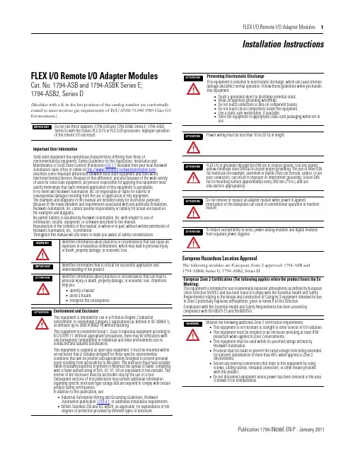
FLEX I/O Remote I/O Adapter Modules 1Publication 1794-IN098E-EN-P - January 2011Installation InstructionsFLEX I/O Remote I/O Adapter ModulesCat. No. 1794-ASB and 1794-ASBK Series E; 1794-ASB2, Series D(Modules with a K in the last position of the catalog number are conformally coated to meet noxious gas requirements of ISA/ANSI-71.040 1985 Class G3 Environment.)European Hazardous Location ApprovalThe following modules are European Zone 2 approved: 1794-ASB and 1794-ASBK Series E; 1794-ASB2, Series DDo not use these adapters (1794-ASB and 1794-ASBK Series E; 1794-ASB2, Series D) with the Classic PLC-5/15 or PLC-5/25 processors. Improper operation of the remote I/O can result.Important User InformationSolid state equipment has operational characteristics differing from those ofelectromechanical equipment. Safety Guidelines for the Application, Installation andMaintenance of Solid State Controls (Publication SGI-1.1 available from your local Rockwell Automation sales office or online at ) describes some important differences between solid state equipment and hard-wiredelectromechanical devices. Because of this difference, and also because of the wide variety of uses for solid state equipment, all persons responsible for applying this equipment must satisfy themselves that each intended application of this equipment is acceptable. In no event will Rockwell Automation, Inc. be responsible or liable for indirect or consequential damages resulting from the use or application of this equipment.The examples and diagrams in this manual are included solely for illustrative purposes. Because of the many variables and requirements associated with any particular installation, Rockwell Automation, Inc. cannot assume responsibility or liability for actual use based on the examples and diagrams.No patent liability is assumed by Rockwell Automation, Inc. with respect to use of information, circuits, equipment, or software described in this manual.Reproduction of the contents of this manual, in whole or in part, without written permission of Rockwell Automation, Inc., is prohibited.Throughout this manual we use notes to make you aware of safety considerations.Identifies information about practices or circumstances that can cause an explosion in a hazardous environment, which may lead to personal injury or death, property damage, or economic loss.Identifies information that is critical for successful application and understanding of the product.Identifies information about practices or circumstances that can lead to personal injury or death, property damage, or economic loss. Attentions help you:•identify a hazard •avoid a hazard•recognize the consequenceEnvironment and EnclosureThis equipment is intended for use in a Pollution Degree 2 industrialenvironment, in overvoltage Category II applications (as defined in IEC 60664-1), at altitudes up to 2000 m (6562 ft) without derating.This equipment is considered Group 1, Class A industrial equipment according to IEC/CISPR 11. Without appropriate precautions, there may be difficulties with electromagnetic compatibility in residential and other environments due to conducted and radiated disturbances.This equipment is supplied as open-type equipment. It must be mounted within an enclosure that is suitably designed for those specific environmentalconditions that will be present and appropriately designed to prevent personal injury resulting from accessibility to live parts. The enclosure must have suitable flame-retardant properties to prevent or minimize the spread of flame, complying with a flame spread rating of 5VA, V2, V1, V0 (or equivalent) if non-metallic. The interior of the enclosure must be accessible only by the use of a tool.Subsequent sections of this publication may contain additional information regarding specific enclosure type ratings that are required to comply with certain product safety certifications. In addition to this publication, see:•Industrial Automation Wiring and Grounding Guidelines, RockwellAutomation publication 1770-4.1, or additional installation requirements.•NEMA Standard 250 and IEC 60529, as applicable, for explanations of the degrees of protection provided by different types of enclosure.Preventing Electrostatic DischargeThis equipment is sensitive to electrostatic discharge, which can cause internal damage and affect normal operation. Follow these guidelines when you handle this equipment:•Touch a grounded object to discharge potential static.•Wear an approved grounding wriststrap.•Do not touch connectors or pins on component boards.•Do not touch circuit components inside the equipment.•Use a static-safe workstation, if available.•Store the equipment in appropriate static-safe packaging when not in use.Power wiring must be less than 10 m (33 ft) in length.FLEX I/O is grounded through the DIN rail to chassis ground. Use zinc plated yellow-chromate steel DIN rail to assure proper grounding. The use of other DIN rail materials (for example, aluminum or plastic) that can corrode, oxidize, or are poor conductors, can result in improper or intermittent grounding. Secure DIN rail to mounting surface approximately every 200 mm (7.8 in.) and use end-anchors appropriately.Do not remove or replace an adapter module while power is applied.Interruption of the backplane can result in unintentional operation or machine motion.To reduce susceptibility to noise, power analog modules and digital modules from separate power supplies.European Zone 2 Certification (The following applies when the product bears the Ex Marking)This equipment is intended for use in potentially explosive atmospheres as defined by European Union Directive 94/9/EC and has been found to comply with the Essential Health and Safety Requirements relating to the design and construction of Category 3 equipment intended for use in Zone 2 potentially explosive atmospheres, given in Annex II to this Directive.Compliance with the Essential Health and Safety Requirements has been assured by compliance with EN 60079-15 and EN 60079-0.Observe the following additional Zone 2 certification requirements:•This equipment is not resistant to sunlight or other sources of UV radiation.•This equipment must be installed in an enclosure providing at least IP54 protection when applied in Zone 2 environments.•This equipment shall be used within its specified ratings defined by Rockwell Automation.•Provision shall be made to prevent the rated voltage from being exceeded by transient disturbances of more than 40% when applied in Zone 2 environments.•Secure any external connections that mate to this equipment by using screws, sliding latches, threaded connectors, or other means provided with this product.•Do not disconnect equipment unless power has been removed or the area is known to be nonhazardous.2 FLEX I/O Remote I/O Adapter Modules Publication 1794-IN098E-EN-P - January 2011North American Hazardous Location ApprovalThe following modules are North American Hazardous Location approved: 1794-ASB and 1794-ASBK Series E; 1794-ASB2, Series D.Remote I/O Adapter 1794-ASB/E, 1794-ASBK/E, 1794-ASB2/DThese adapters are shipped configured for standard addressing mode. InStandard Addressing Mode, the 1794-ASB(K) series E adapter can be used as a replacement for 1794-ASB series A and B remote I/O adapters, and the 1794-ASB2 series D can be used for a replacement for 1794-ASB2 series A 2-slot remote I/O adapters.Installing Your Adapter ModuleMount on a DIN rail before installing the Terminal Base Units1.Hook the lip on the rear of the adapter onto the top of the DIN rail,and rotate the adapter module onto the rail.2.Press the adapter module down onto the DIN rail until flush. Lockingtab C will snap into position and lock the adapter module to the DIN rail.3.If the adapter module does not lock in place, use a screwdriver orsimilar device to move the locking tab down while pressing theadapter module flush onto the DIN rail, and release the locking tab to lock the adapter module in place. If necessary, push up on the locking tab to lock.4.Connect the adapter wiring as shown under “Wiring” later in thisdocument.Mount or Replace the Adapter on an Existing System1.Remove the RIO plug-in connector from the front of the adapter.2.Disconnect any wiring jumpered to the adjacent terminal base.3.Open the module latching mechanism and remove the module fromthe base unit to which the adapter will be attached.4.Push the FlexBus connector toward the right side of the terminal baseto unplug the backplane connection. (When fully retracted, you will see a raised dot on the connector).5.Release the adapter locking tab and remove the adapter module.The following information applies when operating this equipment in hazardous locations:Informations sur l’utilisation de cet équipement en environnements dangereux:Products marked "CL I, DIV 2, GP A, B, C, D" are suitable for use in Class I Division 2 Groups A, B, C, D, Hazardous Locations and nonhazardous locations only. Each product is supplied with markings on the rating nameplate indicating thehazardous location temperature code. When combining products within a system, the most adverse temperature code (lowest "T" number) may be used to help determine the overall temperature code of the system. Combinations of equipment in your system are subject to investigation by the local Authority Having Jurisdiction at the time of installation.Les produits marqués "CL I, DIV 2, GP A, B, C, D" ne conviennent qu'à une utilisation enenvironnements de Classe I Division 2 Groupes A, B, C, D dangereux et non dangereux. Chaque produit est livré avec des marquages sur sa plaque d'identification qui indiquent le code de température pour les environnements dangereux. Lorsque plusieurs produits sont combinés dans un système, le code de température le plus défavorable (code detempérature le plus faible) peut être utilisé pour déterminer le code de température global du système. Les combinaisons d'équipements dans le système sont sujettes à inspection par les autorités locales qualifiées au moment de l'installation.EXPLOSION HAZARD•Do not disconnect equipment unless power has been removed or the area is known to be nonhazardous.•Do not disconnect connections to this equipment unless power has been removed or the area is known to be nonhazardous. Secure any external connections that mate to this equipment by using screws, sliding latches, threaded connectors, or other means provided with this product.•Substitution of components may impair suitability for Class I, Division 2.•IIf this product contains batteries, they must only be changed in an area known to be nonhazardous.RISQUE D’EXPLOSION•Couper le courant ou s'assurer que l'environnemen t est classé non dangereux avant de débrancher l'équipement.•Couper le courant ou s'assurer que l'environnement est classé non dangereux avant de débrancher les connecteurs. Fixer tous les connecteurs externes reliés à cet équipement à l'aide de vis, loquets coulissants, connecteurs filetés ou autres moyens fournis avec ce produit.•La substitution de composants peut rendre cet équipement inadapté à une utilisation en environnement de Classe I, Division 2.•S'assurer que l'environnement est classé non dangereux avant de changer les piles.Component Identification 1Remote I/O Adapter Module 6Remote I/O cable connector 2Indicators7+V DC connections 3Communication reset button (PRL)8-V common connections 4Access door to switches S1 and S29FlexBus connector5Switches S1 and S2 (behind door)If you insert or remove the module while backplane power is on, an electrical arc can occur. This could cause an explosion in hazardous location installations. Be sure that power is removed or the area is nonhazardous before proceeding.If you connect or disconnect the communications cable with power applied to this module or any device on the network, an electrical arc can occur. This could cause an explosion in hazardous location installations. Be sure that power is removed or the area is nonhazardous before proceeding.For Class I Division 2 applications, use only Class I Division 2 listed or recognized accessories and modules approved for used within the 1794 platform.During mounting of all devices, be sure that all debris (metal chips, wire strands, etc.) is kept from falling into the module. Debris that falls into themodule could cause damage on power up.FLEX I/O Remote I/O Adapter Modules 3Publication 1794-IN098E-EN-P - January 20116.Before installing the new adapter, notice the notch on the right rear ofthe adapter. This notch accepts the hook on the terminal base unit. The notch is open at the bottom. The hook and adjacent connection point keep the terminal base and the adapter tight together, reducing the possibility of a break in communication over the backplane.plete the adapter mounting as shown below.8.If the adapter module does not lock in place, use a screwdriver orsimilar device to move the locking tab down while pressing theadapter module flush onto the DIN rail, and release the locking tab to lock the adapter module in place. If necessary, push up on the locking tab to lock.9.Reinstall the module in the adjacent terminal base unit.Connect the Wiring1.Connect the remote I/O cable to the removable remote I/Oconnector.2.Connect +V DC power to the left side of the lower connector,terminal A .3.Connect -V common to the left side of the upper connector,terminal B .4.Connections C and D are used to pass +V DC power (D) and -Vcommon (C) to the next module in the series (if required).Set the Addressing Mode Switches1.Lift the hinged switch cover on the front of the adapter to expose theswitches.2.Set the switches as shown below.3.Cycle power to the adapter after setting the switches.Do not wire more than 2 conductors on any single terminal.ConnectTo terminal Blue Wire - RIO 1Shield Wire - RIO SH Clear Wire - RIO2If you connect or disconnect wiring while the field-side power is on, an electrical arc can occur. This could cause an explosion in hazardous location installations.Be sure that power is removed or the area is nonhazardous before proceeding.Push down and in at the same time to lock the adapter to the DIN rail.When the adapter is locked onto the DIN rail, gently push the FlexBus connector into the adapter to complete the backplaneIf this is the last adapter, you must terminate the remote I/O link here. Use a terminating resistor connected across terminals 1 and 2. Refer to your processor manual for information on the size of the resistor.WARNINGWhen you change switch settings while power is on, an electrical arc can occur. This could cause an explosion in hazardous location installations. Be sure that power is removed or the area is nonhazardous before proceeding.ATTENTIONSome switches on this adapter differ from the switches on previous versions. Make certain that you identify each switch before setting.8 and 16-point Mode Switch SettingsWhen using this addressing modeAndMode Switch 2 S1-1Mode Switch 1 S2-5Mode Switch 0 S2-8Standard (as shipped)8 and/or 16-point modulesSee note 1ON ON Compact8-point modules OFF ON OFF 16-point modules ONONOFFComplementary See complementary table below.Primary Chassis 8-point modules OFFOFF ON Complementary ChassisONOFF ON Complementary See complementary table below.Primary Chassis 16-point modules OFF OFF OFF Complementary ChassisON OFF OFF 1In Standard mode, this switch retains its function as switch position 1 of rack addressing. In standard mode, the module is functionally interchangeable with 1794-ASB series A or B adapters.2In compact mode, 32-point modules appear as 8 or 16-point modules.3When programming block transfers, address analog modules as module 0 if switch S1-1 is on; module 1 if switch S1-1 is off.32-point Mode Switch SettingsWhen using thisaddressing modeAndMode Switch 0 S2-8Mode Switch 1 S2-5Mode Switch 2 S1-1ModeSwitch 3 S2-3Mode Switch 4 S2-4Standard – 328, 16 and/or 32-point modulesONONSee note 1OFFOFFComplementary – 324 FLEX I/O Remote I/O Adapter ModulesPublication 1794-IN098E-EN-P - January 2011Primary Chassis 8, 16 and/or 32-point modulesOFF OFF OFF OFF OFF Complementary ChassisOFF OFF ON OFF OFF 1In Standard – 32 mode, any module in the chassis occupies 32 input points and 32 output points in the input/output data table.2In Complementary – 32 mode, any module in the chassis occupies 32 input points or 32 output points in the input/output data table. If using 8 or 16-point modules,unused points in the data table are zeroed out.First I/O Group 1) (see Important)I/O Rack Number S1-8S1-7I/O Group S1-6…S1-1ON ON 0 (1st)Refer to addressing modetables.OFF ON 2 (2nd)ON OFF 4 (3rd)OFF OFF 6 (4th)1) In 32-point mode, starting quarter must be 0 (S1-8 and S1-7 on).S2-8Mode Switch 0Refer to mode selection switches, above.S2-7Hold Inputs S2-6Rack Fault Select ON Hold inputs ON Disabled (default)OFF Reset inputs OFF EnabledS2-5Mode Switch 1Refer to mode selection switches, munication Rate (32-point Mode Select)Processor Restart Lockout Hold Last State S2-4S2-3Bits/s S2-2S2-1ON ON 57.6k ON Restart ON Reset Outputs OFF ON 115.2k OFFLocked outOFFHold Last StateON OFF 230.4k OFFOFFAuto BaudUse only with 32-point modules.1)These switches used to put the adapter in 32-point mode and perform autobaud.1)Cycle power to the adapter or push the RESET button when the baud rate is changed in the scanner.32-point Mode Switch SettingsWhen using thisaddressing modeAndMode Switch 0 S2-8Mode Switch 1 S2-5Mode Switch 2 S1-1ModeSwitch 3 S2-3Mode Switch 4 S2-4FLEX I/O Remote I/O Adapter Modules 5Publication 1794-IN098E-EN-P - January 2011Complementary I/O Rack Number Switch Settings for PLC-5 Processors(refer to your processor documentation for all other processors) SpecificationsPrimary RackRack Number S1 Switch Position 1747-SN PLC-5654321Rack 0Not Valid ON ON ON ON ON OFF Rack 1Rack 1OFF ON ON ON ON OFF Rack 2Rack 2ON OFF ON ON ON OFF Rack 3Rack 3OFF OFF ON ON ON OFF Rack 4ON ON OFF ON ON OFF Rack 5OFF ON OFF ON ON OFF Rack 6ON OFF OFF ON ON OFF Rack 7OFFOFFOFFONONOFFComplementary RackRack Number S1 Switch Position 1747-SN PLC-5654321Rack 0Not Valid ON ON ON OFF ON ON Rack 1Rack 1OFF ON ON OFF ON ON Rack 2Rack 2ON OFF ON OFF ON ON Rack 3Rack 3OFF OFF ON OFF ON ON Rack 4ON ON OFF OFF ON ON Rack 5OFF ON OFF OFF ON ON Rack 6ON OFF OFF OFF ON ON Rack 7OFFOFFOFFOFFONONSpecifications – 1794-ASB/E, 1794-ASBK/E, and 1794-ASB2/D1794-ASB/E, 1794-ASBK/E1794-ASB2/DI/O capacity 8 modules 2 modulesPower supplyPower supply must be capable of providing a turn-on inrush surge current of 23 A (at 24V DC) for 2 ms for each adapter connected to the power supply.Input voltage range 19.2V…31.2 V DC, 450 mA Output voltage 5V DC, 640 mA Communication rate 57.6 Kbps 115.2 Kbps 230.4 KbpsIndicators Power – green; Adapter active – green; Adapter fault – red; Local fault – redDimensions (H x W x D)87 x 69 x 69 mm 3.4 x 2.7 x 2.7 inchesIsolation voltage 50V (continuous), Basic Insulation TypeType tested at 750V DC for 60 s, power to system, power to RIO, and RIO to systemCurrent draw330 mA at 24V DC; 450 mA max Power dissipation, max 4.6 WThermal dissipation, max1.7BTU/**********Enclosure type rating None (open-style)Wire sizePower and RIO connections:Single wire connection: 0.33... 2.5 mm 2 (22...12 AWG) solid or stranded copper wire rated at 75 °C (167 °F ) or greater 1.2 mm (3/64 in.) insulation maxDouble wire connection: 0.33... 1.3 mm 2 (22...16 AWG) solid or stranded (not intermixed) copper wire rated at 75 °C (167 °F ) or greater 1.2 mm (3/64 in.) insulation max Wire category (1)(1)Use this Conductor Category information for planning conductor routing. Refer to Industrial Automation Wiring and Grounding Guidelines, publication 1770-4.1.3 – on power ports2 – on communications ports Terminal screw torque 0.8 Nm (7 lb-in.)Remote I/O cable Belden 9463 or equivalent Remote I/O connector plugPart number 942029-03North American temp codeT4A IEC temp codeT4Publication 1794-IN098E-EN-P - January 2011 Supersedes Publication 1794-IN098D-EN-P- March 2005Copyright © 2011 Rockwell Automation, Inc. All rights reserved.Mounting DimensionsEnvironmental Conditions Temperature, operating IEC 60068-2-1 (Test Ad, Operating Cold), IEC 60068-2-2 (Test Bd, Operating Dry Heat),IEC 60068-2-14 (Test Nb, Operating Thermal Shock): 0…55 °C (32…131 °F)Temperature,surrounding air, max 55 °C (131 °F)Temperature, nonoperatingIEC 60068-2-1 (Test Ab, Un-packaged Non-operating Cold), IEC 60068-2-2 (Test Bb, Un-packaged Non-operating Dry Heat), IEC 60068-2-14 (Test Na, Un-packaged Non-operating Thermal Shock):-40…85 °C (-40…185 °F)Relative humidity IEC 60068-2-30 (Test Db, Un-packaged Damp Heat):5…95% non-condensingVibration IEC60068-2-6 (Test Fc, Operating): 5 g @ 10…500 HzShock, operating IEC60068-2-27 (Test Ea, Unpackaged shock): 30 gShock, nonoperating IEC60068-2-27 (Test Ea, Unpackaged shock): 50 gEmissions CISPR 11:Group 1, Class A (with appropriate enclosure)ESD immunity IEC 61000-4-2: 8 kV air discharges Radiated RF immunityIEC 61000-4-3:10 V/m with 1 kHz sine-wave 80%AM from 80…2000 MHz 10 V/m with 200 Hz 50% Pulse 100%AM at 900 MHz 10 V/m with 200 Hz 50% Pulse 100%AM at 1890 MHz 3 V/m with 1 kHz sine-wave 80%AM from 2000…2700 MHz EFT/B immunity IEC 61000-4-4:±2 kV at 5 kHz on power ports±2 kV at 5 kHz on communications ports Surge Transient Immunity IEC 61000-4-5:±2 kV line-earth(CM) on communications ports Conducted RF ImmunityIEC 61000-4-6:10 Vrms with 1 kHz sine-wave 80%AM from 150 kHz…80 MHzCertifications (when product is marked)(1)c-UL-usUL Listed Industrial Control Equipment, certified for US and Canada. See UL File E65584.UL Listed for Class I, Division 2 Group A,B,C,D Hazardous Locations, certified for U.S. and Canada. See UL File E194810.CSA CSA Certified Process Control Equipment. See CSA File LR54689C.CSA Certified Process Control Equipment for Class I, Division 2 Group A,B,C,D Hazardous Locations. See CSA File LR69960C.CEEuropean Union 2004/108/EC EMC Directive, compliant with: EN 61326-1; Meas./Control/Lab., Industrial Requirements EN 61000-6-2; Industrial Immunity EN 61000-6-4; Industrial EmissionsEN 61131-2; Programmable Controllers (Clause 8, Zone A & B)C-Tick Australian Radiocommunications Act, compliant with: AS/NZS CISPR 11; Industrial EmissionsExEuropean Union 94/9/EC ATEX Directive, compliant with:EN 60079-15; Potentially Explosive Atmospheres, Protection "n" EN 60079-0; General Requirements II 3 G Ex nA IIC T4 XPublicationsInstallation Instructions 1794-IN098; User Manual 1794-UM009(1)See the Product Certification link at for Declarations of Conformity, Certificates, and other certificationdetails.。

OME-WISE-7000 SERIESWeb-Based IntelligentPAC Controllerse-mail:**************For latest product manuals:User’s Guide®OME-WISE-7115It is the policy of OMEGA Engineering, Inc. to comply with all worldwide safety and EMC/EMI regulations that apply. OMEGA is constantly pursuing certification of its products to the European New Approach Directives. OMEGA will add the CE mark to every appropriate device upon certification.Benelux:Toll-Free: 0800 099 3344TEL: +31 20 347 21 21FAX: +31 20 643 46 43e-mail:**************Czech Republic:Frystatska 184733 01 Karviná, Czech Republic Toll-Free: 0800-1-66342TEL: +420-59-6311899FAX: +420-59-6311114e-mail:*****************France:Toll-Free: 0850 541038TEL: 01 57 32 48 17FAX: 01 57 32 48 18e-mail:***************Servicing Europe:Servicing AsiaU.S.A. and Canada:Sales Service: 1-800-826-6342/1-800-TC-OMEGA ®Customer Service: 1-800-622-2378/1-800-622-BEST ®Engineering Service: 1-800-872-9436/1-800-USA-WHEN ®China:1698 Yishan Road, Unit 102, Minhang DistrictShanghai, China 201103Hotline: 800 819 0559/400 619 0559e-mail:*************.comU.S.A.: ISO 9001 CertifiedOMEGA Engineering, Inc., One Omega Drive P.O. Box 4047, Stamford, CT 06907-0047 USA Toll-Free: 1-800-826-6342TEL: (203) 359-1660 FAX: (203) 359-7700e-mail:**************Servicing North America:For immediate technical or application assistance:Mexico/Latin America:TEL: 001 (203) 359-1660FAX: 001 (203) 359-7700e-mail:*****************Germany/Austria:Daimlerstrasse 26D-75392 Deckenpfronn, Germany Toll-Free************TEL: +49 (0) 7056 9398-0FAX: +49 (0) 7056 9398-29e-mail:*************United Kingdom: ISO 9001 CertifiedOMEGA Engineering Ltd.One Omega DriveRiver Bend Technology Centre, Northbank Irlam, Manchester M44 5BD England Toll-Free: 0800-488-488TEL: +44 (0) 161 777-6611FAX: +44 (0) 161 777-6622e-mail:**************.ukCanada:976 Bergar, Laval (Quebec)H7L 5A1, CanadaToll-Free: 1-800-826-6342TEL: (514) 856-6928 FAX: (514) 856-6886e-mail:*************Table of Contents1Overview (2)2Install/Uninstall OME-WISE-7000 Rule Utility (3)2.1Install OME-WISE-7000 Rule Utility (3)2.2Execute OME-WISE-7000 Rule Utility (4)2.3Uninstall OME-WISE-7000 Rule Utility (5)3Import Rule from a OME-WISE-7000 module to PC (7)4Export Rule from PC to a OME-WISE-7000 module (9)1 OverviewOME-WISE-7000 Rule Utility is an easy-to-use software tool specially designed for OME-WISE-7000 controller, it enables user to perform the following operations:●Import OME-WISE-7000 IF-THEN-ELSE Rule file from aOME-WISE-7000 module to PC●Export IF-THEN-ELSE Rule file from PC to a remoteOME-WISE-7000 moduleBy OME-WISE-7000 Rule Utility, the user can easily retrieve the IF-THEN-ELSE Rule file from a specific OME-WISE-7000 module and this file can be copied to multiple OME-WISE-7000 modules that require the same Rule file, therefore, there is no need to set up rules for each OME-WISE-7000 module individually.2 Install/Uninstall OME-WISE-7000 Rule Utility2.1 Install OME-WISE-7000 Rule UtilityFollow the steps below to install OME-WISE-7000 Rule Utility:●Obtain the OME-WISE-7000 Rule Utility setup file(OME-WISE-7000 Rule Utility Setup 1.x.exe).●Double click the setup file to install the file, you will see awindow pop up as below, click [Next] to continue.●Choose the installation location to install ME-WISE-7000 RuleUtility. Click [Install] to start the installation.●The installation progress will be shown as below; please waittill the installation is completed.●When the installation is completed, click [Finish] to close theprocess.2.2 Execute OME-WISE-7000 Rule UtilityFollow the steps below to execute OME-WISE-7000 Rule Utility:●Taking Windows XP as an example: click [Start] →[AllPrograms] → [OMEGA]→ [OME-WISE-7000 Rule Utility], andthen click “OME-WISE-7000 Rule Utility”under the[OME-WISE-7000 Rule Utility] category to start the program.2.3 Uninstall OME-WISE-7000 Rule UtilityFollow the steps below to uninstall OME-WISE-7000 Rule Utility:●Click [Start]→ [All Programs]→[OMEGA] →[OME-WISE-7000Rule Utility], and then click “Uninstall” under the [OOME-WISE-7000 Rule Utility] category.●You will see a window pop up as below, click [Next] tocontinue.●Click [Uninstall] to uninstall the program.When the uninstall process is completed, click [Finish] to finish the uninstallation.3 Import Rule from a OME-WISE-7000 module to PCFollow the steps below to import Rule from a OME-WISE-7000 module to PC.from the dropdown list.window to select the location for rule file saving operation.2. The selected directory path will be shown in the middle of the utilitySTEP 4: Import WISE Rule4 Export Rule from PC to a OME-WISE-7000 moduleFollow the steps below to export Rule from PC to a OME-WISE-7000 module.dropdown list.Input your OME-WISE-7000 module IP Address in the text box.WARRANTY/DISCLAIMEROMEGA ENGINEERING, INC. warrants this unit to be free of defects in materials and workmanship for a period of 13 months from date of purchase. OMEGA’s WARRAN TY adds an additional one (1)month grace period to the normal one (1) year product warranty to cover handling and shipping time. This ensures that OMEGA’s customers receive maximum coverage on each product.If the unit malfunctions, it must be returned to the factory for evaluation. OMEGA’s Customer Service Department will issue an Authorized Return (AR) number immediately upon phone or written request.Upon examination by OMEGA, if the unit is found to be defective, it will be repaired or replaced at no charge. OMEGA’s WARRANTY does not apply to defects resulting from any action of the purchaser,including but not limited to mishandling, improper interfacing, operation outside of design limits,improper repair, or unauthorized modification. This WARRANTY is VOID if the unit shows evidence of having been tampered with or shows evidence of having been damaged as a result of excessive corrosion; or current, heat, moisture or vibration; improper specification; misapplication; misuse or other operating conditions outside of OMEGA’s control. Components in which wear is not warranted,include but are not limited to contact points, fuses, and triacs.OMEGA is pleased to offer suggestions on the use of its various products. However, OMEGA neither assumes responsibility for any omissions or errors nor assumes liability for any damages that result from the use of its products in accordance with information provided by OMEGA, either verbal or written. OMEGA warrants only that the parts manufactured by the company will be as specified and free of defects. OMEGA MAKES N O OTHER WARRAN TIES OR REPRESEN TATION S OF AN Y KIN D WHATSOEVER,EXPRESSED OR IMPLIED, EXCEPT THAT OF TITLE, AN D ALL IMPLIED WARRAN TIES INCLUDING ANY WARRANTY OF MERCHANTABILITY AND FITNESS FOR A PARTICULAR PURPOSE ARE HEREBY DISCLAIMED. LIMITATION OF LIABILITY: The remedies of purchaser set forth herein are exclusive, and the total liability of OMEGA with respect to this order, whether based on contract, warranty, negligence, indemnification, strict liability or otherwise, shall not exceed the purchase price of the component upon which liability is based. In no event shall OMEGA be liable for consequential, incidental or special damages.CONDITIONS: Equipment sold by OMEGA is not intended to be used, nor shall it be used: (1) as a “Basic Component” under 10 CFR 21 (NRC), used in or with any nuclear installation or activity; or (2)in medical applications or used on humans. Should any Product(s) be used in or with any nuclear installation or activity, medical application, used on humans, or misused in any way, OMEGA assumes no responsibility as set forth in our basic WARRAN TY / DISCLAIMER language, and,additionally, purchaser will indemnify OMEGA and hold OMEGA harmless from any liability or damage whatsoever arising out of the use of the Product(s) in such a manner.RETURN REQUESTS/INQUIRIESDirect all warranty and repair requests/inquiries to the OMEGA Customer Service Department.BEFORE RETURNING ANY PRODUCT(S) TO OMEGA, PURCHASER MUST OBTAIN AN AUTHORIZED RETURN (AR) NUMBER FROM OMEGA’S CUSTOMER SERVICE DEPARTMENT (IN ORDER TO AVOID PROCESSIN G DELAYS). The assigned AR number should then be marked on the outside of the return package and on any correspondence.The purchaser is responsible for shipping charges, freight, insurance and proper packaging to prevent breakage in transit.FOR WARRANTY RETURNS, please have the following information available BEFORE contacting OMEGA:1.Purchase Order number under whichthe product was PURCHASED,2.Model and serial number of the productunder warranty, and3.Repair instructions and/or specificproblems relative to the product.FOR NON-WARRANTY REPAIRS,consult OMEGA for current repair charges. Have the followinginformation available BEFORE contacting OMEGA:1. Purchase Order number to cover the COST of the repair,2.Model and serial number of theproduct, and3.Repair instructions and/or specific problemsrelative to the product.OMEGA’s policy is to make running changes, not model changes, whenever an improvement is possible. This affords our customers the latest in technology and engineering.OMEGA is a registered trademark of OMEGA ENGINEERING, INC.Where Do I Find Everything I Need for Process Measurement and Control?OM EGA…Of Course!Shop online at TEMPERATUREThermocouple, RTD & ThermistorProbes, Connectors, Panels &AssembliesWire: Thermocouple, RTD &ThermistorCalibrators & Ice Point ReferencesRecorders, Controllers & ProcessMonitorsInfrared Pyrometers PRESSURE, STRAIN AND FORCE Transducers & Strain Ga u gesLoad Cells & Pressure Ga u gesDisplacement TransducersInstrumentation & Accessories FLOW/LEVELRotameters, Gas Mass Flowmeters &Flow ComputersAir Velocity IndicatorsTurbine/Paddlewheel SystemsTotalizers & Batch ControllerspH/CONDUCTIVITYpH Electrodes, Testers & AccessoriesBenchtop/Laboratory MetersControllers, Calibrators, Simulators & PumpsIndustrial pH & ConductivityEquipment DATA ACQUISITIONData Acquisition & EngineeringSoftwareCommunications-Based AcquisitionSystemsPlug-in Cards for Apple, IBM &CompatiblesDatalogging SystemsRecorders, Printers & Plotters HEATERSHeating CableCartridge & Strip HeatersImmersion & Band HeatersFlexible HeatersLaboratory Heaters ENVIRONMENTAL MONITORING AND CONTROL Metering & Control InstrumentationRefractometersPumps & TubingAir, Soil & Water MonitorsIndustrial Water & WastewaterTreatmentpH, Conductivity & Dissolved Oxygen Instruments。

Dave SignoriSenior Director, Product ManagementNetwork Insight and NetMRISif Baksh Systems EngineerJohn BelamaricSoftware ArchitectCloud and Network AutomationCustomizing NetMRI NetworkChanges with ConfigurationCommand Scripting (CCS)Agenda•Why script and what scripting options are available in NetMRI •CCS Script Sections•Variables•Lists•Triggers•Filters•Operators•Other CCS Commands and Statements•Viewing, Adding, and Running CCS Scripts•Community Site and TABWhy Use Scripting?•Scripts:•Automate changes to infrastructure devices•Ensure consistent changes•Can be scheduled to run at specific times•Can be triggered to respond to specific events•Scripting reduces the risk of errors being made during execution •No fat fingering•No instant mistakes•Other features to consider before you script …•Config Templates•Config Search•RulesScripting Languages Supported •Focus of this tutorial:•CCS (Change Control Scripting)•Is a proprietary, high-level scripting language designed for network admins •Primary goal is to convert device-specific commands into repeatable tasks •Also supported:•Perl:•Is a general purpose, high-level scripting language•It has a large collection of 3rd party libraries and modules•It has powerful pattern matching and text processing featuresCCS SectionsSection MandatoryScript-Filter XAction XAction-FilterAction-Commands XScript-VariablesOutput-TriggersTriggerTrigger-FilterTrigger-VariablesTrigger-TemplateTrigger-CommandsCCS Sections -SampleSection MandatoryScript-Filter XAction XAction-FilterAction-Commands XScript-VariablesOutput-TriggersTriggerTrigger-Filter Trigger-Variables Trigger-Template Trigger-Commands Using these sectionsSample: Reset Password•Reset Password commands can be written as a CCS script as follows: Script-Filter:$Vendor eq "Cisco" and $sysDescr like /IOS/Script-Variables:$username word "User Name"$password password "New Password"# # # # # # # # # ## This is a commentAction:Set IOS User PasswordAction-Commands:config terminalusername $username password 0 $passwordexitwrite memory Prompt user to type in anusername and passwordOnly run on Cisco IOS devicesExecute commandsSample: Reset Password •The mandatory sections are highlighted in Red •The optional sections are highlighted in BlueScript-Filter:$Vendor eq "Cisco" and $sysDescr like /IOS/ Script-Variables:$username word "User Name"$password password "New Password" # # # # # # # # # ## This is a commentAction:Set IOS User PasswordAction-Commands:config terminalusername $username password 0 $passwordexitwrite memory RequiredRequired Required OptionalVariables•Temporary holding place•Declared using a dollar sign ($) e.g. $username•The value can change during the life of the script•Are global in scope. Available in all sections.•Are updated using the SET: directive•Three types of variables:•Script-Variables: prompt the user at runtime•Trigger-Variables: populated from output of a previous section•Well-Known variables: bundled with NetMRI like $Vendor, $Model, and $Version •When declaring a variable, you must specify a data type•i.e. number (integer), text (string), true/false (boolean)•Regex•$one_digit/^[1-9]$/•Predefined Regex•word, ipaddress, url, phoneno, zipcode, emailLists•CCS Scripts can reference a built-in file called a List. Think of it as a light-weight database.•Use the command getListValue to get the content of the List.•Lists can be created (or imported) under: Config Management -> Job Management -> ListsReading from a List•We use getListValue() to read from the List.SET: $reset= getListValue (Authorized_Users,username,“alice ”,default_passwd,NULL)•Look up from the List Authorized_Users , where username equals “alice ”, and return the corresponding password.•If the user “alice ” cannot be found, return NULL as the password.•Based on the List we defined, we expect to get the password “inW0nderl@nd ” for the user “alice ”.role username default_passwdnew_hire alice inW0nderl@nd new_hireNeoT@keTheRedPillSample with List: Reset Password Script-Filter:$Vendor eq "Cisco" and $sysDescr like /IOS/Script-Variables:$user word “Enter username to reset password"Action:Get default password of a single user from List Authorized_UsersAction-Commands:SET: $reset = getListValue(Authorized_Users,username,$user,default_passwd, “Nope”) Action-Commands: {$reset ne “Nope”}config terminalusername $user password 0 $resetendwr memTriggers•Mini script that only handles a single iteration of a loop•Action section runs, produces output, send it to the Trigger •Trigger section runs, reading in information as input, uses Trigger-Template to extract what’s necessary.•Runs commands in Trigger-Commands using the information extractedCCS Sections –Trigger SampleSection MandatoryScript-Filter XAction XAction-FilterAction-Commands XScript-VariablesOutput-TriggersTriggerTrigger-Filter Trigger-Variables Trigger-Template Trigger-Commands Using these sectionsTriggers•Action-Commands generates a list of output, and calls the Trigger to process the entire list, one item at a time.•Trigger-Commands defines what specific commands are run against each item of the list.•Take the familiar CLI commands sh run | inc username for example, “sh run”is like the Action-Commands, and sends the output to “inc username” to filter out just the usernames.Script-Filter:$Vendor eq "Cisco" and $sysDescr like /IOS/Script-Variables:$user word“Enter username to reset password”Action:Get existing usernamesAction-Commands:show run | inc usernameOutput-Triggers:Update Password# # # # # # # # # # #Trigger:Update PasswordTrigger-Variables:$existing_user wordTrigger-Template:username [[$existing_user]].+password 0.+Trigger-Commands:SET $reset = getListValue(Authorized_Users,username,$existing_user,default_passwd,NULL) conf tusername $existing_user password 0 $resetendwr mem Action, sends output to “Update Password” TriggerTrigger-Template extracts actual username from “show run “ inc username”Execute commands on theusernameScript-Filter:$Vendor eq "Cisco" and $sysDescr like /IOS/Script-Variables:$user word“Enter username to reset password”Action:Get existing usernamesAction-Commands:show run | inc usernameOutput-Triggers:Update Password# # # # # # # # # # #Trigger:Update PasswordTrigger-Variables:$existing_user wordTrigger-Template:username [[$existing_user]].+password 0.+Trigger-Commands:SET $reset = getListValue(Authorized_Users,username,$existing_user,default_passwd,NULL) Trigger-Commands:{$reset ne NULL}conf tusername $existing_user password 0 $resetendwr mem Action, sends output to “Update Password” TriggerTrigger-Template extracts actual username from “show run “ inc username”Execute commands on theusernameFilters•The {} is used as a filter to restrict execution.•Action-Commands and Trigger-Commands can be extended to specify optional filter criteria, restricting execution to cases where specific conditions exist.Example 1:Action-Commands: { $Vendor eq“Cisco” }show interfacesExample 2:Trigger-Commands: { $existing_user eq“Neo” }config tusername $existing_user password 0 $resetFilter Sections•Action-Filter and Trigger-Filter sections can also be used to apply the filter to the entire Action or Trigger section.Example 1:Action-Filter:$Vendor eq“Cisco” show interfacesExample 2:Trigger-Filter:$existing_user eq“Neo”Filters•Filters grant more flexibility and help optimize your code:•They work like an if-then, unless, or case statement•They can be written in two ways:Action:Show Running Config Action-Filter:$Vendor eq“Cisco”Action-Commands:show run | inc username Action:Update Logging DestinationAction-Commands {$sysDescr like /IOS/} logging 205.201.59.69Action-Commands {$sysDescr like /NX-OS/} logging server 205.201.59.69Action-Commands {$sysDescr like /SRX/} set system syslog host 205.201.59.69 any anyOperators•There are several ways to compare two variables•Here are four common approaches:Expressioneq ne in like Definition A equal to B A not equal to B A in list that follows A is similar to BExample Trigger-Commands:{$user eq“Neo”}Action-Commands:{$user ne “admin”}Action-Commands:{$user in[“Neo”,”alice”,”Morpheus”]}Trigger-Commands:{$user like /lic/}Notes Will execute if useris “Neo”Will execute if user isnot “admin”Will execute if user isNeo, alice, or MorpheusWill execute if theusername contains“lic”: either “alice”or “click”Assignment vs. Comparison•The =symbol is NOT the same as the eq comparison operator.•Assignment:•When we use =, we are taking whatever is B and copying it to A:Example: SET: $A = “no”•Comparison:•When we use eq, we are making an evaluation that ends in true or false, by comparing A to B:Example: { $A eq“no” }Putting It All Together -State Variable SampleScript-Filter:$Vendor eq "Cisco" and $sysDescr like /IOS/Script-Variables:$role word “Enter the role, such as new_hire ”Action:Get existing usernamesAction-Commands:show run | inc usernameSET: $ChangesMade = “no”Output-Triggers:Delete user# # # # # # # # # # #Trigger:Delete userTrigger-Variables:$existing_user wordTrigger-Filter:$existing_user ne “admin”Trigger-Template:username [[$existing_user]].+password 0.+Trigger-Commands:SET: $user_role = getListValue(Authorized_Users,username,$existing_user,role,NULL)Trigger-Commands: { $ChangesMade eq “no” and $user_role eq $role }conf tSET: ChangesMade = “yes”Initialize $ChangesMade to “no”Set $ChangesMade to “yes”State Variable Sample (continued)Trigger-Commands: { $user_role eq $role }no username $existing_userIterations# # # # # # # # # # #Action:Write to memory if changes were madeAction-Commands: { $ChangesMade eq “yes” }endwr memOnly execute if$ChangesMade is “yes”Other CCS Commands•Table below summarizes other CCS commands. For more details, refer to the Network Automation CSS Scripting Guide.Command DescriptionDEBUG Provides a mechanism to check whether or not a loop is entered or a statement is executed. Place DEBUG statement in front of the operation to check, and a debug icon will appear next to it if it would be executed.GET-CONFIGS Provides a mechanism to ensure Network Automation has the most up-to-date configurations from the network devices.LOG-INFOGenerates log messages to be sent to the appropriate log facilities, and goes into the standard Network Automation logging.LOG-WARNINGLOG-ERRORLOG-DEBUGPRINT Allows the printing of simple text strings (similar to the C “printf” command) and the printing of values within variables in CCS scripts to output text files.SKIPERROR Turns off error handling for script attributes when an error may appear from the acted-upon device, potentially preventing further job execution.SLEEP Pauses script execution for a specified number of seconds.EXPR Evaluate expressions, discussed next.Comments•Anything after the #symbol is ignored by the script•Use this to add human-readable comments so people reading the script (could be yourself later) understand the code.•For example:Action-Commands:# get current list of network interfaces to decide# which ones to disable# -Neo 04/25/2015DEBUG: Statement•Placing the DEBUG: directive in front of any statement will cause CCS to only print it out in the session log, but not execute the command.•For example:Action-Commands:DEBUG: conf tDEBUG: no username $usernameDEBUG: endDEBUG: wr memOperatorsOperator DescriptionA| B A if it is neither null nor 0, otherwise BA& B A if neither argument is null or 0, otherwise 0A <B A is less than BA <=B A is less than or equal to BA =B A is equal to BA !=B A is not equal to BA >=B A is greater than or equal to BA >B A is greater than BA +B Arithmetic sum of A and BA –B Arithmetic difference of A and BA *B Arithmetic product of A and BA /B Arithmetic quotient of A divided by BA %B Arithmetic remainder of A divided by BEXPR Command•EXPR performs more advanced comparison and evaluations •For example, increase $A by 1 (useful for iterating) EXPR: $A = $A + 1•Or compute the product of $A times $BEXPR: $A = $A * $BViewing, Adding, and Running CCS Scripts •Config Management -> JobManagement -> Scripts•Click Add to createAdding New CCS Script Levels Low, Medium, and High, indicatethe permission level needed to executethe scriptCategory is anything you want totype in that helps you organizescriptsName of scriptBody of CCS scriptRunning CCS Scripts•Config Management -> Job Management -> Scripts -> Run nowViewing Status and Job Details •Config Management -> Job Management -> Job HistoryViewing Status and Job DetailsCustomer Participation OpportunitiesTechnical Advisory Boards•10 TABs including NetMRI and Network Insight•Roadmap and early look at pre-releasedfeatures•Input for future enhancements•Best practices•First NetMRI session held on May 12th•Request membership at the Infoblox CommunitySite。

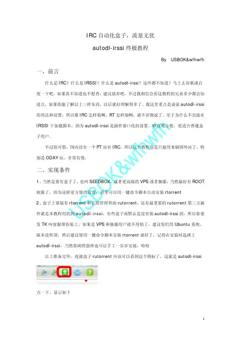
,够直观方便,点一下,显示如下再选择相应的菜单如果能显示出来,就证明安装正常了。
比如选择Announce Channels 会显示如下:顺便说一点的是Announce Channels这里就是插件支持的IRC站点了,相当一个查询作用,后面填服务器和频道就参照这里的行了。
三、详细设置菜单有五项,但我们只要关注的是Fiters,IRC Servers和Trackers这三个设置就基本可以灵活运用了1、IRC Servers填IRC服务器和频道,各站不同,但基本一样,可先查看Announce Channels有没在支持列表中,再进相关的PT站有关IRC页面查看具体的登录参数,比如端口Port,通用是6667,选SSL就6697,默认6667的甚至可以不填。
从没进过的IRC要填邮箱进行注册昵称,这个昵称就是你PT站的登录名,如果注册过的可以不填邮箱了,像换盒子一下面Invite的几行,有些特殊站点要的,像PTN,SHD,BMTV之类的是特殊命令邀请进IRC的,要填第一行,人家PT网站上面的IRC页或FAQ都有提示你怎么做的,你上去看看就行,以下是BMTV的例子,注意第一次注册邮箱要补上,换盒子就不用填了。
像SCC要从网站上邀请进IRC,所以要这么填后面三行,这三行分别为:/ircCookie:uid=XXXXXX;pass=XXXXXXXXXXXXXXXXXXXannounce=yesCOOKIE的取得是很简单的,直接在打开的网页地址栏输入下面一句,再回车就显示出来了javascript:document.innerHTML=document.cookie2、Trackers因为IRC脚本自动下载种子文件是在种子下载连接加入你的PASSKEY或者COOKIE 组成完整连接加载种子文件的,所以要在Trackers填写你自己的对应PT站的PASSKEY 或者COOKIE,具体填什么上面是有英文提示的,对应做就行了。


––––Automating the Asset Model Import Process ArcSight ESM Asset ManagementChris MaennerCybersecurity Threat Discovery EngineerChris Maenner,CISSPSecurity Technology AuditSenior Security ConsultantInformation Assurance EngineerAnti-Tamper EngineerDatabase administrator Cybersecurity Threat Discovery EngineerAgenda•Asset Model Importance and Tools •ArcSight Archive Utility•ArcSight Asset Model Connector•What’s the difference between the tools?•Generating Asset File(s)•Comcast’s Asset Automation Process •Benefits, Best Practices, and ResourcesD e v ic e s Assigning a Priority Formula (Threat Level Formula)More accurate organizational asset management Risk rate assets by criticalityVulnerability tracking of assetsRouter type?Who’s laptop?Is it mobile?Cloud Service?ArcSight ESM Asset Modeling Importance•The ArcSight Archive utility is a multi-function command-line tool that can be used by ArcSight Administrators to perform routine maintenance, such as back-up and restore from an Extensible Markup Language (XML) file•Why do we care to use this utility?•Creating, removing, or updating asset objects:•Asset Ranges•Assets•Categories •Customers•Filters •Locations •Networks•Zones ESM Administrator’s Guide : Administrative Commands : ESM ArcSight Commands•Further details can be found:ArcSight Archive UtilityArcSight Asset Model Import Connector•The Asset Model Import Connector allows you to import asset objects from a comma separated value (CSV) file. This enables you to create and maintain ESM Network Model data, and keep this data in sync with the data in your Asset Management system.•Why do we care to use this utility?•Add, Move, Remove, or Update:•Asset(s)•Categories•Zones•Further details can be found:ESM 101 : The Network Model : Ways to Populate the Network ModelWhat’s the difference between the tools?Archive Utility ProcessESM XML •Command is mandatory for archive •/opt/arcsight/manager/bin/arcsight archive -u <USER> -m <FQDN> -i -f assets.xml •Data validation prior to import •Verbose output to user during import process (by default to the *terminal)Asset Model Import Connector ProcessESMXML CSV Connector •The connector does not validate the file data•The connector is a wrapper that uses the Archive Utility tool•No verbose output to determine if there were issues during importPros vs ConsArchive Utility Tool Asset Model Import Connector Asset import progress information✅❌Asset file setup❌✅Asset tool setup✅❌Ease of use✅✅File documentation support❌✅•XML is the only file format supported•Three stage process occurs:o Determine if the objects are to be Inserted, Updated, or Removedo Stage importing of objectso Complete organization of objects and will either insert, update, or remove objects•Provides progress information while doing the archive operation •CSV is the only file format supported•Three stage process occurs:o Determine if the objects are to be Inserted, Updated, or Removedo Stage importing of objectso Complete organization of objects and will either insert, update, or remove objects•Does not provide progress information while doing the archive operation•CSV file content must match parser configurationArcSight Archive Utility Asset Model Import Connector Generating Asset File(s)•Type*•Name*•IP Address*•MAC Address •Host Name •External ID •Alias•Parent Group URI •Description •Zone URI •Location URI •CategoriesAssets•Type*•Name*•External ID •Alias•Parent Group URI •DescriptionCategories•Type*•Name*•Address1•Address2•City •State•Postal Code • 2 Digit Country Code•External ID •Alias•Parent Group URI •DescriptionCustomer•Type*•Name*•Latitude •Longitude •City•Region Code •Postal Code •Country• 2 Digit Country Code•External ID •Alias•Parent Group URI •DescriptionLocations•Type*•Name*•External ID •Alias•Parent Group URI •Description •Customer URI •Location URINetworks•Type*•Name*•Start Address*•End Address*•Dynamic Addressing •External ID •Alias•Parent Group URI •Location URI •Network URI •CategoriesZonesObject element types that are used to create XML file(s):•The column title signifies the “Type” element•Not listed in presentation are “Asset Ranges” and “Filters”ArcSight Archive Utility Support*Mandatory elementsArcSight Resource Generator Tool –Java Archive (JAR) tool that can generate XML files •ArcSight Resource Generator Tool dissected (decompiled):•Replaced the ArcSight Resource Generator Tool with a custom Python script using the following modules:•lxml(http://lxml.de)•Used to write XML elements to each XML file type•More efficient parser compared to ElementTree(Python standard library since version 2.5)•netaddr(https:///pypi/netaddr)• A network address manipulation library•Used to support Zones XML creation•Provides a simple method to grab network and broadcast address from network CIDR•requests (/en/master)•Provides native thread-safe connection pooling•Powered by urllib3 (https://urllib3.readthedocs.io/en/latest)•This module is used as a personal preference, urllib2 would be fine to use•Use this module to query Google Maps API to get up-to-date latitude and longitude coordinatesAsset Model Import Connector SupportCSV example for Asset Model ConnectoraddAsset,Active,Activated on 07/04/2016,,192.168.1.1,G0:0D:B3:RG:3R:SS,foo-server.local,fooServer,myFooServer,/All Assets/Organization/Foo Corp,Router to perform,fooServer,/All Zones/Organization/Foo Corp/Fooville/Fooville192.168.1.0/24,/All Locations/Organization/FooCorp/Fooville,/All Asset Categories/System Asset Categories/Criticality/High;/All Asset Categories/System Asset Categories/Compliance/PCIDetails:•Mandatory column types: [“Action”, “Active/Inactive”, “AssetName”, “IP Address”]•Action types:[“addAsset”, “updateAsset”, “removeAsset”, “addCategory”, “removeCategory”, “addZone”, “removeZone”, ”moveAsset”]•Column types: ["Active/Inactive Reason", "MAC Address", "HostName", "External ID", "Alias", "ParentGroupURI", "OldParentGroupURI", "AssetDescription", "ZoneURI", "LocationURI", "AssetCategory"]•AssetCategory:to add multiple categories, the string delimeter must have a semicolonMore details can be found in: HP ArcSight Asset Model Import FlexConnector Developer’s GuideCSV Parser Example and Template for the Asset Model Connector####### BEGIN ###### comments.start.with=# delimiter=,token.count=15token[0].name=Actiontoken[0].type=Stringtoken[1].name=Activetoken[1].type=Stringtoken[2].name=ActiveReason token[2].type=Stringtoken[3].name=AssetName token[3].type=Stringtoken[4].name=Iptoken[4].type=Stringtoken[5].name=Mactoken[5].type=Stringtoken[6].name=HostName token[6].type=String####### CONTINUED ######token[7].name=ExternalIDtoken[7].type=Stringtoken[8].name=Aliastoken[8].type=Stringtoken[9].name=ParentGroupUritoken[9].type=Stringtoken[10].name=OldParentGroupUritoken[10].type=Stringtoken[11].name=AssetDescriptiontoken[11].type=Stringtoken[12].name=ZoneUritoken[12].type=Stringtoken[13].name=LocationUritoken[13].type=Stringtoken[14].name=AssetCategorytoken[14].type=String####### CONTINUED #########keep these 7 fields unchanged###additionaldata.enabled=trueadditionaldata.duplicate.keys.allowed=falseevent.deviceEventCategory=__stringConstant(Asset)event.deviceCustomString1Label=__stringConstant(model.sender)event.deviceCustomString1=__stringConstant(flexcsv)event.deviceCustomString2Label=__stringConstant(model.template)event.deviceCustomString2=__stringConstant(mic/asset_flexfile/asset.vm)###field mappings###event.deviceVendor=__getVendor(CSV File)event.deviceProduct=__stringConstant(Assets)event.deviceAction=Actionadditionaldata.Action=Actionevent.externalId=ExternalIdevent.flexString1=AssetName#following mappings maybe removed in future but required for nowadditionaldata.UniqueUserId=AssetNameevent.destinationUserId=AssetName####### END ######Make sure to set the following fields on the ESM connector:123ESM 6.8cArchive ToolExternal AssetsNote :•Each resource needs to be unique, duplicates will cause import failures •Order of import is vital due to how assets inherit object attributes1.Customer2.Locationwork4.Category5.Zone6.AssetComcast’s Asset Automation ProcessAsset Model Benefits•Automates the reconnaissance of the environment •Helps management with training staff•Assigns threat level formula’s to assets•Categorizes high/low value assets•Easier transition in understanding environment •Helps teams focus on job requirements:•Incident Response•Focus on closing cases and root cause analysis of incidents •Threat Discovery (Hunting)•Risk rates targets to help with determining hunting exercises •Provides accurate threat details for your organizationBest Practices•Prior to import:•Assets must have unique fully qualified domain name (FQDN) or host name•Asset must have unique IP Address•Asset must only be in one zone•Categories are accurate and do not contain forward or back slashes •Limit categories due to system resources (pending system architecture)•Updating assets:•If asset moved between zones, make sure ParentGroupURI is properly associated •Removing assets:•If you have a vulnerability scanner updating assets, all historical vulnerabilitydata will be removed from assetResources•ESM 101 for ESM 6.8c: https:///docs/DOC-11937•CORRe Internals: https:///docs/DOC-11998•ESM Asset Model Import FlexConnector Configuration Guide: https:///docs/DOC-11925•ESM Asset Model FlexConnector Developer's Guide for ESM 6.8c: https:///docs/DOC-11989•SN21: How it Works: Assets, Zones, Networks and Customers https:///docs/DOC-1130•SmartConnector for Qualys QualysGuard Filehttps:///docs/DOC-2372Questions?We are hiring!––––。

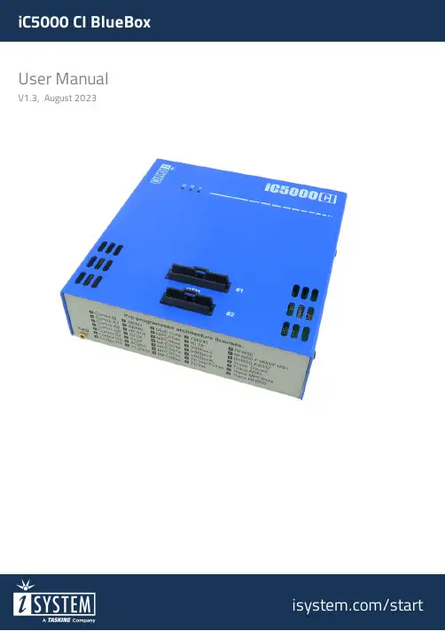
User ManualV1.3, August 2023/startGeneral safety instructionsPlease read the following safety precautions carefully before putting this device to use to avoid any personal injuries, damage to the instrument, or to the target system. Use this instrument only for its intended purpose as specified by this manual to prevent potential hazards.Use included power cord and power supplyThe enclosed power supply has been approved for use by iSYSTEM. Please contact iSYSTEM if you need to consider an alternative power.Use grounding wirePrior to applying power to either the BlueBox or the target, connect the device and the target system together with the included grounding wire. This is to avoid potential damage caused by any voltage difference between the device and the target system.Use proper overvoltage protectionEnsure proper protection to avoid exposing the BlueBox device or the operator to overvoltage surges (e.g. caused by thunderstorm, mains power).Do not operate without coverDo not operate the device with cover removed.Avoid circuit and wire exposureDo not touch exposed components or wires when the device is powered.Do not operate with suspected damageIf you suspect damage may have occurred, the BlueBox device must be inspected by qualified service personnel before further operation.Do not operate the device outside its rated supply voltage or environmental rangeConsult with iSYSTEM before using equipment outside of the parameters provided in this manual.This symbol is used within the manual to highlight further safety notices.ContentsPackage content (4)Specifications (5)Operation (6)Device description (7)Hardware Setup and Configuration (9)Accessories (10)Declarations (11)iC5000 CI BlueBox On-Chip Analyzer is a hardware platform which allows hardware debugging and testing a wide range of embedded microcontroller platforms that are based on a variety of processor architectures and is implemented into Continuous Integration (CI) infrastructures. Functionality can be further extended with the addition of our Active Probes. iC5000 CI comes with almost the same functionality as the standalone products and is licensed on yearly subscription basis.The standard iC5000 CI order is delivered with the following components:iC5000 CI withpre-assembled DTM module25 cm 40-pin ribbon cable Power supplyOrdering code: IC50000-CI Ordering code:IC50020-25Ordering code:IC30000-PSUSB 2.0 cable Ethernet cable Grounding wireOrdering code: BB-USB20-180Ordering code:BB-ETHCAT5-200Ordering code:BB-WIREDevice overviewA – Two connectors, marked #1 and #2. These connectors are the interface to the target microcontroller. Depending on the target microcontroller debug features, the supplied ribbon-cables will need to be connected to either connector #1 only or connectors #1 and #2.B – The indicator lights provide the status of the hardware:Power Indicator·On – Powered on·Off – Powered offR – Running Indicator·On – Target microcontroller is executing code·Off – Target microcontroller is haltedF –Free Indicator·On – BlueBox is available for a connection from a host PC·Off – Active connection to the BlueBox from a host PC existsC – The grounding socket (GND) should be used, together with the supplied Grounding wire to create an electrical connection between the BlueBox and the target circuitry. The socket is suitable for a 2 mm Multi Contact Plug (also known as a Banana Plug) if building a longer or a replacement cable on your own.D – Power SwitchE – Power Supply SocketThe socket and plug are latching to stop the plug from being accidentally pulled out of the socket. To remove the power plug from the socket, always pull gently of the sleeve of the plug and never on the wire.F – 10/100 Ethernet SocketG – USB 2.0 SocketRecommended to use the USB 2.0 cable. The USB 2.0 interface provides the highest possible data transfer rate of the two available interfaces. Use of alternate cables must be undertaken at your own risk.Both the 10/100 Ethernet Socket and the USB 2.0 Socket can be connected to a network/PC simultaneously. The active interface will be determined by whichever interface winIDEA connects to first.When powering on the system, switch the BlueBox unit onWhen powering down the system, power off the Target before powering off the BlueBoxunit!FBridge port is not Ethernet port!Use only original iSYSTEM accessories for powering and connecting with the BlueBoxunit. Consult with iSYSTEM before attempting to use any other accessory. Differences between BlueBox CI and BlueBoxFor more information refer toFor a detailed visual presentation of the hardware setup and configuration, refer toGetting started tutorial1. Connect the power supply cable. BlueBox should be switched off.2. First connect via USB. Later you can configure TCP/IP connection to work remotely.3. Connect the Grounding wire to the BlueBox and the Target.IfBlueBox and the Target can exceed well over 1000V even before any of the devices arepoweredleading to the possible destruction of electronic components.4. Connect the ribbon cable to the Debug Adapter. Connect the ribbon cable to the Debug Adapter.5. Connect the ribbon cable to the BlueBox connector(s).6. Connect the Debug Adapter to the Target. To disconnect squeeze the two metal latches on the ribbon cables.7. Power on procedure:·BlueBox·Target8. Install winIDEA and create a new workspace.Various debug adapters are available to connect the iC5000 CI to a wide range target debug connector as commonly found on microcontroller development boards.More information about our products onEU Declaration of Conformity (DoC)WeiSYSTEM AG für InformatiksystemeCarl-Zeiss-Str. 1, 85247 SchwabhausenGermanydeclare that the DoC is issued under our sole responsibility and belongs to the following product:BlueBox debugger and analyzer solutionType: iC3000, iC5000, iC5500, iC5700, iC6000, iTAG.2KIdentification allowing traceability:Object of the declaration is identified by a product type and unique serial number for eachindividual device.The object of declaration described above is in conformity with the relevant Union harmonizationlegislation:EMC directive 2014/30/EU and RoHS directive 2011/65/EU The following harmonized standards and technical specifications have been applied to:·EN 55032: 2012·EN 55024: 2010·EN 61000 - 3 - 2: 2014·EN 61000 - 3 - 3: 2013Signed for and on behalf of:Schwabhausen,21. March 2017iSYSTEM AG f. Informatiksysteme - Carl-Zeiss-Str. 1 - 85247 Schwabhausen - USt-IdNr. DE128231221 Vorstand: Erol Simsek, Werner Fischer, Martin Gröstenberger - AG: München HRB 148751 - St-Nr.:115/120/30027Bank: Sparkasse Dachau BLZ 70051540 Account 904045 - IBAN: DE82700515400000904045 - BIC:BYLADEM1DAHVisit our website for:·Support - /support ·Tutorials - /getting-started ·Knowledge Base - 。
ContentsIntroductionESP-RZXe Controller Features (1)LNK WiFi Enabled (1)Controls and Indicators (1)Key Functions (1)Normal OperationAuto (2)Off (2)Basic ProgrammingDate/Time (2)Zone Schedule (3)Select Zone (3)Set Watering Run Times (3)Set Watering Start Times (3)Set Watering Start Days (4)Custom Days (4)Odd Days (4)Even Days (4)Cyclic Days (4)Additional FeaturesManual Watering (5)Water ALL Zones: (5)Water ONE Zone: (6)Seasonal Adjust ...............................................6InstallationIndoor Model (7)Mount Controller (7)Connect Power (7)Outdoor Model (8)Mount Controller (8)Connect Power (8)Wiring Connections (10)Connect Zone Valves (10)Connect Master Valve (10)Connect Pump Start Relay (11)Connect Rain Sensor (11)Options and Special FeaturesInstall Batteries (12)Reset Button (12)Rain Sensor Bypass (12)Set Bypass for All Zones (12)TroubleshootingError Detection (13)Watering Issues (13)Electrical Issues (13)Programming Chart (14)ESP-RZXe Controller Installation Guide and Operations ManualIntroductionESP-RZXe Controller FeaturesThe ESP-RZXe controller has a variety of advanced water management features, including:• Zone based programming allows independent irrigation scheduling for different areas (Zones), based on the specific water requirements for each area.• Programs can be set to water on selected days of the week, odd or even calendar days, or at custom intervals, allowing LNK WiFi EnabledThe LNK WiFi Module allows remote connection to a Rain Bird ESP-RZXE Controller using an Apple iOS or Android compatible smart device. The mobile application allows remote access and configuration of one or more irrigation controllers.For more information on the LNK WiFi Module and the value this product can provide for your ESP-RZXe controller, please visit: Press the AUTO key to resume normal operation whenever programming is completed and to moni-tor active watering.NOTE: Unless the OFF key is pressed, the controller will revert to AUTO mode by default after 10 minutes,if no programming activity (key presses) occurs dur-ing that time.In Auto Mode:The display shows the current time, date and day of the week:During Watering:The display shows a blinking sprinkler symbol, the active Zone number and watering Run Time remaining for that Zone.ZoneRunTimefor the active Zone as desired.Press NEXT to immediately cancel watering for the active Zone and advance to the next Zone in the irri-gation queue.OffCancel all active watering immediately and disable automatic irrigation.Press the OFF key to immediately cancel all active watering.Programmed irrigation schedules remain stored in memory even when the controller is turned off or if power is lost.Press the DATE/TIME key.Press + or – to set the month (M); then press NEXT to select and set the day (D), then year (YYYY).DATEPress + or –to set the hour (ensuring that AM/PMsetting is correct); then press NEXT to select and set the minutes.TIMEdate and time in the event of a power outage. See“Install Batteries” for details.Zone ScheduleCreate customized irrigation schedules to run automat-ically at specific times, durations and intervals. Press the ZONE SCHEDULE key.1Select ZoneZones are designated areas (for example, “Rose Gar-den”) that you define as locations for watering. See“Programming Chart” for details.Press + or –to select the desired Zone Number;then press NEXT .Zone2Set Watering Run Times Watering Run Times are durations (for example, 20minutes) set for watering.NOTE: Run Times can be set between 1 to 199 min-utes. Press + or –to set the desired Run Time (MIN); thenpress NEXT .RUN TIMEWatering Start Times are times of day at which water-ing is set to begin.NOTE: A total of up to six Start Times (1-6) are avail-able for each Zone.Press + or –to set the 1st Start Time (ensuring thatAM/PM setting is correct); then press NEXT . NOTE: Start Time adjustments are set in 10 minuteincrements.START TIMEthat Zone.NOTE:Pressing NEXT when -:- (OFF) is blinking onthe display will advance to Step 4.4 Set Watering Start DaysWatering Start Days are the calendar days or intervals (for example, Monday, Wednesday and Friday) on which watering is allowed.Press + or – to select one of four available Watering Start Day options:a. Custom Days -To schedule watering to occur onselected days of the week, go to 4a.b. Odd Days - To schedule watering to occur on all oddcalendar days (1,3,5...29 etc.), go to 4b.c. Even Days - To schedule watering to occur on alleven calendar days (2,4,6...30 etc.), go to 4c.d. Cyclic Days - To schedule watering to occur at inter-vals (every 2 days, or 3 days, etc.), go to 4d.Press + or – to select then press NEXTSelection Day. Cursor will then advance to the nextSelection Day.SELECTION DAY Press ON or OFF to set each subsequent day of the week as desired.Press + or – to select13529,,...then pressNEXTPress + or – to select24630,,...then pressNEXTPress + or – to select then pressNEXTPress + or –key to set the desired Day Cycle; thenpress NEXT.DAY then press NEXT .STARTDATEthe current day cycle. The display will always updateto show the next scheduled irrigation day.THENREPEAT steps 1-4 for additional Zones as desired.Water ALL Zones:Press the MANUAL WATERING key.ALL Zones appears as the default selection; pressNEXT to continue.ALL NEXTto begin watering.RUNTIMEPress + or –to adjust watering Run Time remainingfor the active Zone as desired. Press NEXT to immediately cancel watering for theactive Zone and advance to the next Zone in the irri-gation queue.Water ONE Zone:Press the MANUAL WATERING key.Press + or – to select any ONE Zone; then press NEXT.NEXT to begin watering.RUNTIMEPress + or – to adjust watering Run Time remaining for the active Zone as desired.Seasonal AdjustIncrease or decrease watering duration (Run Times) for all Zones.Press the SEASONAL ADJUST key.Press + or – to increase or decrease the SEASONAL ADJUST percentage setting.NOTE: The SEASONAL ADJUST value can be adjusted from -90% to +100%. For example, a +50% adjust-ment means a Run Time of 10 minutes will become15 minutes.Connect PowerThe ESP-RZXe outdoor controller has an internal trans-former that reduces supply voltage (120 VAC in U.S. models; 230 VAC in international models; 240 VAC in Australian mod-els) to 24 VAC. You will need to connect power supply wires to the transformer’s three wires. (Line, Neutral, Ground).replace the wiring compartment cover and secure itwith the screw.Wiring ConnectionsConnect the valve wires for each Zone and for (optional) Master Valve, Pump Start Relay or Rain Sensor.NOTE: If installing an outdoor model, route all field wires through conduit or through the knock-out onback of the unit.Connect Zone ValvesConnect the power wire from each Zone valve to the corresponding Zone number on the controller termi-Connect Master ValveConnect an optional Master Valve to the ESP-RZXe controller.Connect the power wire from the master valve to theConnect Pump Start RelayConnect an optional Pump Start Relay to the ESP-RZXe controller.Pumps are used in some places to draw water from a well or other source. If you are activating a pump from the control-ler, you must install a pump start relay.A pump start relay connects to the controller in the same way as a Master Valve, but connects differently at the water source.NOTE: the ESP-RZXe controller DOES NOT providemain power for a pump.Connect the common wire from the pump start relayto the COMMON (C) terminal.Connect Rain SensorConnect an optional rain sensor to the ESP-RZXe con-Rain Sensor BypassThe controller can be set manually to either OBEY or IGNORE a Rain Sensor.NOTE: Rain Sensor Bypass settings cannot bechanged while the controller is irrigating.Set Bypass for All ZonesThe NO RAIN SENSOR symbol will show on the dis-play when IGNORE is selected.TroubleshootingError DetectionThe ESP-RZXe controller has a built-in error detection that senses a electrical short circuit or overload condition on a Zone’s output line.In the event of an error condition, the following steps take place regarding the error:• The affected Zone number and “Err” alert message will show on the display when the unit is in either AUTO or MANUAL WATERING mode.Watering IssuesElectrical Issues• All irrigation for the affected Zone is cancelled and watering advances to the next operable Zone in the irrigation queue. NOTE: The controller will attempt to water the affectedZone again at the next scheduled watering. Completion ofa successful watering will clear the error condition associ-ated with that Zone.Enter Watering Start Times (up to six total).Select Watering Start Days (checkbox). If Custom Days isselected, circle the days of the week to water. If Cyclic Days is selected, enter a number from 1-14.Programming ChartBefore programming your controller, plan the watering sched-ule for each Zone using the Programming Chart and keep it for reference.In the Zone Description column, enter a brief descriptionsuch as “front lawn” or “side yard”. Enter the Watering Run Time for that Zone.CertificationsSafety InformationRain Bird ESP-RZXeon the WebEnglishEspañolSpainwww.rainbird.eswifi-pro.rainbird.esMexico.mxF rançaiswww.rainbird.frwifi-pro.rainbird.frPortuguês.br.brItalianowww.rainbird.itwifi-pro.rainbird.itDeutschewww.rainbird.dewifi-pro.rainbird.deTürk.tr.trPусскийwww.rainbirdrussia.ruwifi-pro.rainbirdrussia.ruPolskiewww.rainbird.plwifi-pro.rainbird.pl中文Rain+BirdtTechnical SupportRain Bird Europe SNCRain Bird France SNCBAT A - Parc Clamar240, rue René Descartes BP 40072 13792 Aix-en-Provence Cedex 3FRANCETel: (33) 4 42 24 44 61***************·www.rainbird.eu ***************·www.rainbird.fr Rain Bird Deutschland GmbHKönigstraße 10c70173 StuttgartDEUTSCHLANDTel: +49 (0) 711 222 54 158***************Rain Bird Ibérica S.A.C/ Valentín Beato, 22 2ª Izq. fdo28037 MadridESPAÑATel: (34) 91 632 48 10****************·www.rainbird.es********************www.rainbird.ptRain Bird TurkeyÇamlık Mh. Dinç Sokak Sk. No.4 D:59-60 34760 Ümraniye, İstanbulTÜRKIYETel: (90) 216 443 75 23***************.tr Rain Bird Australia Pty Ltd.Unit 13, Level185 Mt Derrimut RoadPO Box 183Deer Park, VIC 3023Tel: 1800 724 624info@.au/auRain Bird Brasil Ltda.Rua Marques Póvoa, 215Bairro Osvaldo RezendeUberlândia, MG, BrasilCEP 38.400-438Tel: 55 (34) 3221-8210.brRain Bird Corporation 6991 East Southpoint Road Tucson, AZ 85756USATel: (520) 741-6100Rain Bird Corporation970 W. Sierra Madre Ave.Azusa, CA 91702USATel: (626) 812-3400Rain Bird International145 North Grand Ave.Glendora, CA 91741USATel: +1 (626) 963-9311Rain Bird Europe S.A.R.L240 Rue René DescartesBatiment A PARC CLAMARBP 4007213792 AIX EN PROVENCE CEDEX 3FranceTel : (33) 4 42 24 44 61 2018 Rain Bird Corporationt Registered trademark of Rain Bird Corporationwww.rainbird.eu。
自动化系统(ILASII)培训材料(二)第一部分ILAS系统客户端的安装及系统的进入一、客户端安装1、在本地计算机的C盘中,建立一名目“ILASII”2、搜寻计算机“202.197.69.8”,查找到一共享名目“ILASII”3、进入该名目,复制全部文件及名目(有一名目,名为“客户端下载不需要",不需复制),并将全部复制内容粘贴到本地的“ILASII”名目中。
4、进入本地ILASMin”名目,找到文件“ILASIIMD.exe”文件,将其建立一快捷方式放在桌面。
5、将本地“ILASII”名目下的文件“ILASII.ini”放至系统名目(假定为C:\windows),并修改其内容。
其中,IP:是指ILASll服务器的地址;LocalPath:是指本地ILAS存放的位置。
如IP=202.197.69.3 ;LoCalPath=CVaSIl。
其他内容无须修改。
二、系统的进入1、双击桌面上的ILAS图标(其文字显示为“ILASIIMD”),会消失一个图片界面2、在该界面范围内,任意点击某个地方,会在右下角消失一个登录窗口3、在该窗口的“登录名称”栏中愉入用户名;在“用户密码”栏中输入愉入密码,点击“确定”即可登录进入ILAS系统。
4、假如需要修改密码,在该窗口的右下方,点击“》”,在“新密码”栏中输入新的密码,在“确认密码”栏中,重复输入新的密码,所修改的密码马上生效。
5、在正式系统中,全部原ILAS工作人员的帐号、密码不变,原丹诚系统的工作人员(铁道校区)用户名为其中文姓名的首字母(三个字母,假如姓名只有两个字,则重夏其次个字,假如超过三个字,则取前三个字,密码为用户名加123组成。
如王书方老师,其用户名为WSf, 其密码为wsf123;特殊状况,此外考虑)其次部分相关参数设置重要说明:全部涉及订户的地方,一律选择CSU;全部涉及新编书目、复制书目、确认书目的时候,均帚要设*“书目掌握号区号\全部涉及百防生成条码的时候,在t,自动生成条码”前均需划上勾且需设置”条码号分区号,一、采访子系统参数设置1、订购处理的参数设置订户:CSU 书目掌握号区号:中文图书处理输入01;外文图书处理输入02订购批号:(采编部自定并报系统管理员)如ZTD2003001 (分别表示:中文;图书;订购;2003年;第一批书)采访币制I、2均选择“CNY”(特殊状况除外)经费来源:选择“财政拨款”文献来源:选择“书商订购”(特殊状况除外)载体类型:选择“Efl刷型”(特殊状况除外)装祯类型:选择“平装”(特殊状况除外)另:“存盘检测”、“编目存盘追加”、详细需要追加拼音的字段、“连接项”的选择状况由采编部统一制定并将制定内容告知系统管理员。
Run Azure IoT Edge Runtime on EdgeBox-RPI-200 device running Debian 11 (ARM32v7)Table of ContentsIntroductionStep 1: PrerequisitesStep 2: Prepare your DeviceStep 3: Manual Test for Azure IoT Edge on deviceStep 4: Additional informationStep 5: Additional LinksIntroductionEdgeBox-RPI-200 series are all-in-one Raspberry Pi-based industrial edge computing controllers, combining multiple industrial purposes. Designed as high-scalability and rugged industrial hardware, mounted with rich IO resources and supported by the great Raspberry Pi industrial software ecosystem, it is an ideal choice for smart automation and Industrial Internet of Things(IIoT) solutions.This document describes how to connect EdgeBox-RPI-200 device running Debian 11 (ARM32v7) with Azure IoT Edge Runtime pre-installed and Device Management. This multi-step process includes: Configuring Azure IoT HubRegistering your IoT deviceBuild and Deploy client component to test device management capabilityStep 1: PrerequisitesYou should have the following items ready before beginning the process:Create an Azure accountSign up to Azure PortalSetup your IoT hubAdd the Edge DeviceAdd the Edge ModulesStep 2: Prepare your Device1. Power on the device. Supply 9~36V to Pin1 and Pin2 of the Multi-Func phoenix connector.2. Connect the PC and EdgeBox-RPI-200 USB Type-C (Console).3. Check the OS version with lsb_release command.$ lsb_release -ircDistributor ID: RaspbianRelease: 11Codename: bullseyeIf your OS is older than Debian 11 (Bullseye), please upgrade your OS.The OS supported by Microsoft for Tier 1 is Debian 11 (Bullseye), but the EdgeBox-RPI-200 ships from the factory with Raspberry Pi OS ported Debian 10 (Buster). So you need to upgrade yourOS.$ sudo rm /etc/apt/.sources.list.swp$ sudo rm /etc/apt/sources.list.d/raspi.list$ sudo echo"deb /raspbian/ buster maincontrib non-free rpi" | sudo tee /etc/apt/sources.list$ sudo apt update$ sudo apt full-upgrade$ sudo reboot$ sudo echo"deb /raspbian/ bullseye maincontrib non-free rpi" | sudo tee /etc/apt/sources.list$ sudo apt update$ sudo apt install nodejs# Restart services during package upgrades without asking? ---> Yes$ sudo apt install gcc-8-base$ sudo apt full-upgrade# Configuration file '/etc/default/useradd' ---> Y# Configuration file '/etc/plymouth/plymouthd.conf' ---> Y$ sudo apt autoclean$ sudo apt autoremove$ sudo sed -i 's/dtoverlay=vc4-fkms-v3d/#dtoverlay=vc4-fkms-v3d/g'/boot/config.txt$ sudo sed -i 's/\[all\]/\[all\]\ndtoverlay=vc4-kms-v3d/' /boot/config.txt$ sudo rebootStep 3: Manual Test for Azure IoT Edge on device3.1 Edge Runtime Enabled1. Register your device2. View registered devices and retrieve provisioning information3. Install IoT Edge$ curl https:///config/debian/11/packages-microsoft-prod.deb > ./packages-microsoft-prod.deb$ sudo apt install ./packages-microsoft-prod.deb$ rm ./packages-microsoft-prod.deb4. Install a container engine$ sudo apt-get update$ sudo apt-get install moby-engine$ sudo vi /etc/docker/daemon.json$ sudo systemctl restart dockerSet the default logging driver to the local logging driver as shown in the example below.{"log-driver": "local"}5. Install the IoT Edge runtime$ sudo apt-get update$ sudo apt-get install aziot-edge defender-iot-micro-agent-edge6. Provision the device with its cloud identity$ sudo iotedge config mp --connection-string 'PRIMARY_CONNECTION_STRING'$ sudo iotedge config apply3.2 Check the iotedge daemonOpen the command prompt on your IoT Edge device , confirm that the Azure IoT edge Daemon is under running statesudo iotedge system statusOpen the command prompt on your IoT Edge device, confirm that the module deployed from the cloud is running on your IoT Edge device$ sudo iotedge listOn the device details page of the Azure, you should see the runtime modules - edgeAgent, edgeHub and SimulatedTemperatureSensor modules are under running statusStep 4: Additional informationEdgeBox-RPI-200 User ManualThe Idiot-Proof Guide to Upgrading Raspberry Pi from Buster to BullseyeStep 5: Additional Links What is Azure IoT EdgeAzure IoT Edge supported platformsDevelop your own IoT Edge modules。
CAREL ir33 Quick reference HandbookMAIN FEATURES OF THE INSTRUMENTUSER INTERFACE1. ON/OFF switch button – UP button to increase temperature values2. DOWN button to decrease values - Activates/deactivates the manual defrost3. SET temperature button4. Prg/mute button5. Malfunctioning or failure warning icon6. High/Low temperature alarm icon7. icon is ON when defrost process starts8. icon is ON when compressor starts9. icon is ON when evaporator fans starts10. icon is ON when an auxiliary output is activePOWER OFFWhen the instruments is switched off the display shows the label OFF andall internal relays are disabled (not energized)POWER ONWhen the controller is switched on a special procedure tests the display and the keypad. The display is completely ON for 2 secondsThree segments “---“ on the display are visualized for 2 seconds and thenthe controller becomes operativeCompressor icons flashes and the compressor activation is delayed by safety timesSET CAVITY TEMPERATURETo display or to set the temperature, proceeds as follows:Keep SET button pressed for more than 1 second. The instruments displays the temperature valueIncrease or decrease the set point using UP/DOWN buttons, until reaching the desired valuePress SETbutton again to confirm the new value FREQUENT USE PARAMETER(TYPE F)Press Prg/mute button more than 5 seconds the instruments shows the code of the first adjustable parameter (type “F”) – if an alarm is active,pressing this button, the buzzer is muted first.FREQUENTLY USE PARAMETER LIST : St, rd, rt, rH, rL, dI, dt1, dt2, dP1, dP2, dd, d8, d/1, d/2, AL, AH, Ad, F1, Fd CONFIGURATION PARAMETER (TYPE C)Access to the configuration parameters is protected by password that avoid unwanted modifications or access by unauthorized personel. Proceeds as follows:1. Press Prg/Mute and Set buttons together for more than 3seconds; display shows a flashing numerical code “0” that indicates the password prompt 2. Press UP button to set the password – CAREL thermoregulators are provided with password set to 11 (the code of the password allows access to the configuration parameters) 3. Confirm by pressing the Set button to enter in the programming mode and scroll up/down the operating parameters list4. Display shows the code of the first adjustable type “C” parameter/2MANUALDEFROSTManual defrost is activated or deactivated ifDEF/DOWNbutton is keep pressed more than 5 seconds.When defrost starts display shows dFb (defrost begining)Defrost’s warning icon is ON when defrost is activeDefrost can be interrupted simply by pressing again the DEF/DOWN button more than 5 seconds. Display shows the message dFE (defrost End)MODIFYING THE PARAMETERSAfter having displayed the first operating parameter, either type C or type F, it is necessary to procedes as follows:1. PressUP/DOWN button until reaching the parameter to bemodified. When scrolling the list, an icon appears on the displaythat indicates the category the parameter belongs to2. Press SET button to display the parameter’s value3. Increase or decrease its value using UP/DOWN button4. Press again SET button to temporarily save the new value, closing the parameter adjustment and return to the display of theparameter codeRepeat the operations from point 1 to 4STORING THENEW ASSIGNED VALUESTo definitively store the new values of the modified parameters, procede as follows: 1. Press the Prg/mute button more than 5 seconds 2. Display shows the label ProThe controller step out the parameter setting procedure and the displayshows current temperature value.RESET ANYMODIFICATIONS All modifications made to the parameters, temporarily stored into the internally memory of the controller, can be cancelled and normal operation resumed by not pressing any button for 60 second, thus allowing theparameter setting session to expire due to timeoutHOW TO CHECKCAVITY PROBE TEMPERATURETo check current temperature measured by a single installed probe, proceeds as follow: 1. refers to the previous step how to get in the configuration parameter session - type C parameter2. scroll the configuration parameter list, by using UP/DOWNbuttons, until display shows the parameter /C1 (calibration or offset for cavity probe) 3. press SET button4. display shows the probe calibration value, used to correct thetemperature measured by the probe by means of an offset5. Press again SET button6. display shows the current temperature value measured by theprobe7. press SET button to return to display of the parameter code /C1HOW TO CHECK EVAPORATOR TEMPERATURECurrent evaporator probe temperature is available by means of theparameter /C2 (calibration or offset for evaporator probe) To check temperature value proceeds as previously indicated from step 1 to step 2, considering the configuration parameter /C2HOW TO CHECKCONDENSER TEMPERATUREIf the condenser probe is installed it is possible to check condenser temperature by means of the parameter /C3 (calibration or offset for condenser probe) To check temperature value proceeds as previously indicated from step 1to step 2, considering the configuration parameter /C3BE CAREFUL ⇒ DO NOT ADJUST THE CALIBRATION VALUETABLE OF OPERATING PARAMETERS N° Code Range U.M. Description TEMPERATURE PROBE MANAGEMENT PARAMETERS 1/2 0...15 -- Measurement stability 2/3 0...15 -- Probe display response 3/4 0…100 -- Virtual probe 4/5 0/1 Flag Selection °C or °F 5/6 0/1 Flag Decimal point 6/tl 1…6 -- Display on terminal 7/tE 0...6 -- Display on external terminal 8/P 0…2 -- Type of probe 9/A2 0…3 -- Configuration probe 2 10/A3 0…3 -- Configuration probe 3 11/c1 -20…20 °C/°F (/10) Calibration probe 1 12/c2 -20…20 °C/°F (/10) Calibration probe 2 13 /c3-20…20 °C/°F (/10) Calibration probe 3 TEMPERATURE CONTROL PARAMETERS 14 Str1…r2 °C/°F set point temperature 15 rd0.1…20 °C/°F Control delta 16 rn0…60 °C/°F Dead band 17 rr0.1…20 °C/°F Reverse differential for control with dead band 18 r1-50...r2 °C/°F Minimum set point allowed 19 r2r1…200 °C/°F Maximum set point allowed 20 r30...2 Flag Operating mode 21 r4-20...20 °C/°F Automatic night-time set point variation 22 r50...1 °C/°F Enable temperature monitoring 23 rt0...999 °C/°F Temperature monitoring interval 24 rH- °C/°F Maximum temperature read 25 rL- °C/°F Minimum temperature read COMPRESSOR SAFETY TIME AND ACTIVATION PARAMETERS 26 c00...15 Minutes Compressor and fan delay on start-up 27 c10…15 Minutes Minimum time between two sequent compressor starts 28 c20...15 Minutes Minimum compressor OFF time 29 c30...15 Minutes Minimum compressor ON time 30 c40…100 Minutes Duty setting 31 cc0…15 Hours Continuous cycle duration 32 c60…15 Hours Alarm bypass after continuous cycle 33 c70...900 Seconds Maximum pump down time 34c8 0...60 Seconds Compressor start delay after open PD valve35 c9 0...1 Flag Enable autostart function in PD36 c10 0...1 Flag Select Pump down by time or pressure37 c11 0...250 Seconds Second compressor delayDEFROST MANAGEMENT PARAMETERS38 d0 0...4 Flag Type of defrost40 dI 0…250 Hours Interval between defrosts41 dt1 -50…200 °C/°F End defrost temperature, evaporator42 dt2 -50…200 °C/°F End defrost temperature, aux evap.43 dtP 0...200 °C/°F Defrost end temperature when defrost has done with compressor OFF and fans ON44 dP1 1…250 Minutes Maximum defrost duration, evaporator45 dP2 1…250 Minutes Maximum defrost duration, aux evap.46 d3 0...250 Minutes Defrost start delay47 d4 0/1 Flag Enable defrost on start-up48 d5 0…250 Minutes Defrost delay on start-up49 d6 0...2 -- Display on hold during defrost50 dd 0…15 Minutes Dripping time after defrost51 d8 0…15 Hours Alarm bypass after defrost52 d8d 0…250 Hours Alarm bypass after door open53 d9 0/1 Flag Defrost priority over compressor protectors54 d/1 - °C/°F Defrost probe 1 read55 d/2 - °C/°F Defrost probe 1 read56 dC 0/1 Flag Time base (0=h/m;1=m/s)57 d10 0...250 Hours Compressor running time for defrost58 d11 -20...20 °C/°F Running time temperature for defrost59 d12 0...3 -- Advanced defrost60 dn 1...100 % Nominal defrost duration61 dH 0...100 -- Proportional factor, variation in dI ALARM MANAGEMENT PARAMETERS62 A0 0.1…20.0 °C/°F Alarm (fan) differential63 A1 0/1 Flag Relative or Absolute Alarm64 AL -50…200 °C/°F Low temperature alarm threshold65 AH -50…200 °C/°F High temperature alarm threshold66 Ad 0…250 Minutes Low and high temperature signal delay67 A4 0…15 Flag Digital input 1 configuration68 A5 0…15 Flag Digital input 1 configuration69 A6 0…100 Minutes Stop compressor from external alarm70 A7 0…250 Minutes External alarm detection delay71 A8 0/1 Flag Enable alarms ‘Ed1’ and ‘Ed2’72 Ac 0...200 °C/°F High condenser temperature alarm73 AE 0.1...20 °C/°F High condenser temperature alarm differential74 Acd 0…250 Minutes High condenser temperature alarm delay75 AF 0…250 Seconds Light sensor OFF time76 ALF -50...200 °C/°F Antifreeze alarm threshold77 AdF 0…15 Minutes Antifreeze alarm delay78 ACS -50...200 °C/°F Alarm Clean Setpoint79 ACd 0.1...50 Minutes Alarm Clean differentialEVAPORATOR FAN MANAGEMENT PARAMETERS81 F0 0...2 Flag Fan management82 F1 -50...200 °C/°F Fan stop temperature83 F2 0/1 Flag Fan OFF with compressor OFF84 F3 0/1 Flag Fans in defrost85 Fd 0…15 Minutes Fan OFF after dripping86 F4 -50...200 °C/°F Condenser fan stop temperature87 F5 0.1...20 °C/°F Condenser fan start differentialGENERAL CONFIGURATION PARAMETERS88 H0 0…207 -- Serial address89 H1 0...10 Flag Function of relay 490 H2 0...6 Flag Disable keypad/IR91 H4 0/1 Flag Disable buzzer92 H6 0...255 -- Lock keypad93 H8 0/1 Flag Select activation of output with time band94 H9 0/1 Flag Enable set point variation with time band95 Hdh -50...200 °C/°F Anti-sweat heater offset96 CCd 0...999 -- Clean Counter Days97 Cd 0...999 -- Clean days98 SAn 0...255 -- Service Alarms number99 SAr 0...1 Flag Service Alarms counter reset San100 CAn 0...255 -- Clean Alarm counter101 CAr 0...1 Flag Clean Alarm counter resetNOTE 1:Above operating parameters are available for all range of CAREL thermoregulators. Particularly all green highlighted parameters are available on new CAREL controller ir33 IRELF0HN245, currently installed on HD cabinets and countersNOTE 2:Blu highlighted operating parameters listed above are not influential for the functioning of the appliance.SERVICE ALLARMS AND SIGNALSSERVICE ALARMSSERVICE ALARMS DUE TO MALFUNCTIONING OR FAILURE PRODUCE A WARNING SIGNALS ON THE DISPLAY BY MEAN OF THE SERVICE ICONCAVITY PROBE FAULTIn case of cavity probe faulty or malfunctioning display shows the error signal rE and E0 (cavity probe S1 fault) alternately The appliance works however and compressor starts are controlled by time (15 mins is ON and 15 mins is OFF) until the fault is resolved.This alarm signal is automatically restored when the faulty erased and the probe replacedDuring this time interval the service alarm icon flashes on display and an acoustic signal is ENABLEDEVAPORATOR PROBE FAULTYIn case of evaporator probe faulty or malfunctioning display shows an error signal E1 (evaporator probe S2 fault).This alarm signal is automatically restored when the faulty erased and the probe replaced During this time interval the service alarm icon flashes on display. Acoustic signal is DISABLED CONDENSER PROBE FAULTY (WHEN INSTALLEDON BOARD)In case of condenser probe faulty or malfunctioning display shows the error signal SEr and E2 (condenser probe S3 fault) alternately This alarm signal is automatically restored when the faulty erased and the probe replaced During this time interval the service alarm icon flashes on display. Acoustic signal is DISABLEDCLEAN ALARMIf a probe is set as the condenser probe, the condenser temperature can be monitored to signal the high temperature alarm, due to obstruction orfoulingIn this case a warning signal is visualized and display shows the errorsignal CLn and the temperature measured by the condenser probe alternatelyService alarm icon is flashing and the acoustic signal DISABLED The clean alarm is reset to zero by pressing the Prg/mute button and the service alarm icon cancelled on displayTEMPERATURE ALARMS AND SIGNALSTEMPERATUREALARMS HIGH OR LOW TEMPERATURE ALARMS DUE TO MALFUNCTIONING OR COMPONENTS FAILURE PRODUCE A WARNING SIGNALS ON THE DISPLAY BY MEAN OF THE ALARM ICON .LOWTEMPERATURE ALARMIn case of low cavity temperature, referred to the cavity probe, the display shows a flashing error code LO . Temperature alarm icon is flashing and the acoustic signal ACTIVE. This alarm is automatically reset when cavity temperature increase over the minimum temperature threshold, depending from the parameter ALHIGHTEMPERATURE ALARMIn case of high cavity temperature, referred to the cavity probe, the display shows a flashing error code HI . Temperature alarm icon is flashing and the acoustic signal ACTIVE. This alarm is automatically reset when cavity temperature decrease under the maximum temperature threshold, depending from the parameter AHCONDENSER FAN ALARMIn case of condenser fan faulty or malfunctioning display shows a flashing error code SErTemperature alarm icon is flashing and the acoustic signal ACTIVEPressing Prg/mute button the buzzer is DISABLED but the alarm signal is still active and shown on the displayCONNECTIONSFollows all electrical connections available on ir33 CAREL controller , currently used in productionIRELC0HN215 (646R05100) Æ installed on STD BEN and CL freezer counter and STD BEN cabinet provided with internal lightIRELF0EN215 (646R04700) Æ installed on all STD BEN refrigerated counters, 400Lt refrigerated cabinets and all STD BEN cabinets without lightIRELF0HN245 (646R09300) Æ installed on HD counters and cabinetsIRELF0EN225 Æ installed on digital ROLL–INIRELF0EHD15 Æ installed on 400Lt FREEZER cabinet。
Xcelsius教程版本:1。
0日期:2009年07月18日文档控制本文件的目的仅为提供信息,并不构成任何合同或具法律约束力的文件的基础。
发布的这份文件并不保证内含信息是否正确或者是否将保持正确,也不保证使用其中的信息将确保对相关服务或设备的操作正确无误。
文件内容如有改动,恕不另行通知。
修订历史一、Xcelsius介绍 (5)1.1 Xcelsius工具说明 (5)1。
2 Xcelsius版本介绍 (5)1.3 Xcelsius的向后兼容性 (5)1。
4 Xcelsius系统介绍 (6)1。
5 Xcelsius工作原理的说明 (6)二,Xcelsius的使用 (7)三、Xcelsius开发的一般性步骤 (9)3.1 添加电子表格数据 (9)3.2 选择链接到部件的数据源. (9)3.3 预览和发布可视化文件 (10)四、Xcelsius开发中主要部件功能的介绍 (10)4。
1 统计图部件 (10)4.1。
1 折线图 (11)4。
1。
2 饼图 (12)4.1.3 OHLC 统计图和阴阳烛图 (12)4。
1.4条形图和柱形图 (12)4。
1。
5 堆积柱形图和堆积条形图 (13)4.1。
6 组合图 (13)4。
1.7 气泡图 (14)4。
1。
8 XY 散点图 (14)4.1。
9 面积图 (14)4。
1.10 堆积面积图与面积堆积图 (15)4。
1。
11雷达图和填充式雷达图 (15)4。
1。
12树图 (16)4。
2 容器部件 (16)4。
2。
1面板容器 (16)4.2.2选项卡集 (17)4.3 选择器部件 (17)4。
3。
1 折叠式菜单 (18)4。
3。
2 复选框 (18)4。
3。
3 组合框 (18)4。
3。
4过滤器 (18)4。
3。
5 鱼眼图片菜单 (19)4.3。
6 滑动图片菜单 (19)4.3。
7 图标 (19)4。
3.8 标签式菜单 (19)4.3。
9 列表框 (20)4。
3。
10 列表视图 (20)4。
,够直观方便,
点一下,显示如下
再选择相应的菜单如果能显示出来,就证明安装正常了。
比如选择Announce Channels 会显示如下:顺便说一点的是Announce Channels这里就是插件支持的IRC站点了,相当一个查询作用,后面填服务器和频道就参照这里的行了。
三、详细设置
菜单有五项,但我们只要关注的是Fiters,IRC Servers和Trackers这三个设置就基本可以灵活运用了
1、IRC Servers
填IRC服务器和频道,各站不同,但基本一样,可先查看Announce Channels有没在支持列表中,再进相关的PT站有关IRC页面查看具体的登录参数,比如端口Port,通用是6667,选SSL就6697,默认6667的甚至可以不填。
从没进过的IRC要填邮箱进行注册昵称,这个昵称就是你PT站的登录名,如果注册过的可以不填邮箱了,像换盒子一
下面Invite的几行,有些特殊站点要的,像PTN,SHD,BMTV之类的是特殊命令邀请进IRC的,要填第一行,人家PT网站上面的IRC页或FAQ都有提示你怎么做的,你上去看看就行,以下是BMTV的例子,注意第一次注册邮箱要补上,换盒子就不用填了。
像SCC要从网站上邀请进IRC,所以要这么填后面三行,
这三行分别为:
/irc
Cookie:uid=XXXXXX;pass=XXXXXXXXXXXXXXXXXXX
announce=yes
COOKIE的取得是很简单的,直接在打开的网页地址栏输入下面一句,再回车就显示出来了
javascript:document.innerHTML=document.cookie
2、Trackers
因为IRC脚本自动下载种子文件是在种子下载连接加入你的PASSKEY或者COOKIE 组成完整连接加载种子文件的,所以要在Trackers填写你自己的对应PT站的PASSKEY 或者COOKIE,具体填什么上面是有英文提示的,对应做就行了。
Dalay是延迟加载种子
3、Fiters
重点来了,过滤器设置,autodl-irssi的过滤器很强大,可按种子名的关键字过滤,也可以按站点的分类过滤,甚至可以按Pretime过滤,还能设置下载文件的大小范围,固定时间的流量(对限流量的盒子有用),这些实在是比RSS强大了NN倍。
对于TV Show/Movie 和Music还有更详细的设置,我就不一一细说,同学们可以自己领会,呵呵,下面还是看图设置吧,TL热门美剧组的设置
高级选项,选择过滤分类,所以全是Packs ,逗号分隔
Movies/Packs,TV/Packs,Games/Packs,XXX/Packs,Music/Packs
下面是下载的设置,每个过滤器最好都独立设置吧,因为如果选择rtorrent方式,可加标签,设置下载位置,Ratio group分享组设置(分享组设置可以设置做种多久后自动删除,因为盒子空间有限,这是自动化下载必不可少的,要先在分享组设置再行选择)。
当然其它种子下载方式也可以选择,像Watch目录,甚至可以加载种子到其它盒子UT的WEBUI 都行。
四、收尾
以上都设置好了后,基本设置完毕了,有些细节的地方可以自己触类旁通的,但怎样知道是不是正常工作呢,看RUT的autodl-irssi状态显示,关键是有(/join)一般就表示已
开始监听IRC频道了
有种子加载是下面这个样子的
如果以上都设置好还是没有以上的效果出来,请认真检查是不是都填对了,如果还是不能解决问题,那就要学一下SCREEN的用法了,连接SSH打开IRSSI的SCREEN,看看是不是登录不上或者有其它什么问题,因为IRSSI里面都有提示的,一般常见的问题是识别不了你的昵称或密码不对的。
详细请自行搜索SCREEN+IRSSI怎样用,因为这不是本教程的重点,因为autodl-irssi的出现就是避免screen下的烦人命令。
但我友情提示下,一键脚本安装的后,RT和IRSSI是在同一个SCREEN里的,默认第一个是IRSSI,第二个是RT,切换使用CTRL+A再CTRl+N或P就可以看到不同的SCREEN了。