海尔电热水器ES50H-A6(E)(U1)说明书
- 格式:pdf
- 大小:5.19 MB
- 文档页数:16
电热水器安全使用方法汇总以前人们在冬天洗澡和洗碗、洗衣服没有热水,长期如此很多女性朋友的收拾粗糙无光泽。
想着哪天能用上热水洗还是非常不错的。
因此各种热水器就如雨偶春笋般出现在,而电热水器就是众多产品中的拳头产品。
那么它安全吗,怎么安全使用它等这些问题就陆续出现了,今天土拨鼠小编就给大家讲讲电热水器在使用时的一些安全事项,让大家在暖和的时候更安全。
电热水器安全使用方法1、电热水器新安装后一定要产品按照说明书规范执操作,先通水然后在通电的顺序,不然有可能因为干烧导致电热水器损坏。
2、在洗浴结束后需先进行先断水,然后在断电的顺序,定期对电热水器中的滤网进行清洗,否则水垢有可能会堵塞滤网哦。
3、使用后需要对热水器进行清洁,但是不可忘记镁棒也是需要换新的,否则内胆损坏了就麻烦了。
4、电热水器除了使用自来水之外,也使用了其他的电子元器件和零部件,因此使用久了就会出现加热、出水量、费电等情况。
所以对于电热水器的水垢和其他有害物质的清理和清洗就变得特别重要。
否则有可能会导致机器工作状态不良或者直接出现故障。
产品也需要像人一样定期进行洗澡除脏。
市场上目前在售的各种型号和品牌的产品主要是用户厨卫方面的,比较知名的有皇明、四季沐歌、美的、海尔、樱花等品牌。
安全注意事项1、洗浴前的热水调试工作是必不可少的,但是不能将淋浴花洒对准热水器或者开关插座及人体,否则过冷可能让人打喷嚏感冒,过热直接烫伤人体皮肤。
而热水器和开关插座的话,则会造成线路受潮漏电,或者直接短路发生危险。
2、沐浴结束后先关闭混水阀,然后关闭热水器电源,待花洒水流基本干净了,然后挂在花洒支架上。
最后,吹干头发打开窗户进行通风,去除卫浴间的雾气。
3、对于长期不住人房间的热水器最好关闭掉,在关闭前一定要将内胆的水彻底放干净,防止时间太长水变质或者内胆出现水垢。
操作办法是关闭冷水阀,将混水阀开关拧到热水最大处且抬高最最高位置,此时即可进行排水。
待水流干净后关闭混水阀、关闭热水器开关、断开电源。

31 SCHEMATICS 12/1/2005INDEXPAGE3.AC Panel4.230V AC Panel5.AC Panel Schematic6.230v AC Panel Schematic7.AC Wire Kit8.Stage Wire Kits-DVD Option Kit10.DC Panel11.DC Panel Schematic12.DC Panel Connectors14. Hull Harness15. Hull Harness Wire List16. Hull Harness Connectors17. Deck Harness18. Deck Harness Wire List19. Deck Harness Connectors20. Auto Fire System Schematic21. High Water Pump System Schematic22. Engine Panel Area SchematicPage 1REVISION DATE: 11/16/05 31 WIRE KITS WIRE SIZE COLOR LENGTH EYE EYE DESCRIPTION HOUSE BATTERY #11/ORED 10'3/8"3/8"BATT TO SW-HOUSE11/OYELLOW 9.5'5/16"3/8"BATT TO GND-HOUSE1YANMAR STARTER 2 GARED 8' 6"5/16"3/8"START TO STUD-YAN 2 GAYELLOW 8'3/8"3/8"ENGINE TO GND-YAN GNDS 6 GAGREEN/YELLOW 23'1/4"3/8"ARCH GND 6 GAGREEN/YELLOW 10' 6"1/4"5/8"CHAINPLATE PORT 6 GAGREEN/YELLOW 10' 6"1/4"5/8"CHAINPLATE STBD 10 GAGREEN/YELLOW 20'FUEL FILL GRD4 GA GREEN/YELLOW 30"1/4"3/8"MAST POST TO KEEL WIRE SIZE COLOR LENGTH EYE EYE DESCRIPTION SHORE POWER10-3ROMEX 15'SP1GNDS 6 GA GREEN/YELLOW 8'3/8"1/2"PEDESTAL GND WIRE SIZE COLOR LENGTH EYE EYE DESCRIPTION HOUSE BATTERY #21/ORED 11'3/8"3/8"BATT TO SW-HOUSE21/OYELLOW 2'3/8"3/8"BATT TO GND-HOUSE2BATT. CHAR. P/N 100284014-3ROMEX 7'BATT CHARGER INVERTER (120V)1/ORED 12"3/8"3/8"INV TO FUSE 1/ORED 18"3/8"3/8"FUSE TO SW 1/OYELLOW 18"5/16"3/8"INV TO GND 1/OGREEN/YELLOW 18"5/16"1/4"INV CASE TO GND 10-3ROMEX 7'INV IN 10-3ROMEX 7'INV OUT INVERTER (230V)1/ORED 1'3/8"3/8"FUSE TO SW 1/OGREEN/YELLOW 18"5/16"1/4"INV CASE TO GND 10-3ROMEX 7'INV IN 10-3ROMEX 7'INV OUT WINDLASS 2 GARED 24'1/4"5/16"BREAKER TO BOX-WL 2 GAYELLOW 24'3/8"5/16"GND TO BOX-WL 2 GARED 16"3/8"1/4"WINDLASS JUMPER BILGE KEEL 12 GABROWN 12' BILGE PUMP (+) 12 GAYELLOW 12' BILGE PUMP (-)AIR CONDITIONING 10-3ROMEX 18' AIR COND 14-3ROMEX 8'AC PUMP WIRE SIZE COLOR LENGTH EYE EYE DESCRIPTION WINDLASS2 GA RED 1' 6"5/16"5/16"BOX TO MOTOR-WL2 GA RED 1' 6"5/16"5/16"BOX TO MOTOR-WL 16 GA YELLOW 1' 6"5/16"F-spade CONTROL BOX NEG.ELECTRICAL STAGE 56STAGE 24A-MODULE P/NMODULE STAGE 24AOPTIONSSTAGE 34-DECK RIGGING P/N 1013359HUNTER 31 DC HULL HARNESS11/18/2005 WIRE#GAUGE COLOR LENGTH FUNCTION110RED/BLACK138"REFRIGERATION210YELLOW120"REFRIGERATION NEG.316ORANGE/RED134"LPG PANEL SW416YELLOW116"LPG INDICATOR NEG.3A16ORANGE/GREEN260"LPG SOLENOID (+)4A16YELLOW296"LPG SOLENOID (-)512BROWN/RED110"BILGE MANUAL SW612BROWN/ORANGE96"BILGE AUTO712YELLOW92"BILGE NEG.86YELLOW68"DC MDP NEG.96ORANGE/RED64"DC MDP POWER1012TAN46"BILGE POWER118ORANGE/GREEN34"BATTERY CHARGER128ORANGE/RED34"BATTERY CHARGER138YELLOW36"BATTERY CHARGER NEG1816PINK/BLACK206"WATER SENSOR (S)1916YELLOW202"WATER SENSOR (-)2212BROWN/BLUE310"BLOWER2312YELLOW292"BLOWER NEG.2412BROWN130"WATER PUMP2512YELLOW112"WATER PUMP NEG.2812BROWN/BLACK140"SUMP PUMP SW28A12BROWN/BLACK132"SUMP PUMP2912YELLOW62"SUMP PUMP NEG.3216RED/BLUE222"CO DETECTOR3316YELLOW204"CO DETECTOR NEG.32A16RED/BLUE388"CO DETECTOR33A16YELLOW354"CO DETECTOR NEG.3412RED174"12V OUTLET3512YELLOW156"12V OUTLET NEG.OUTLET3612RED 236"12V3712YELLOW202"12V OUTLET NEG.4116PINK184"FUEL SENSOR (S)4216YELLOW184"FUEL SENSOR (-)506YELLOW32"NEG BUS JUMPER6110WHITE/GREEN106"HW PUMP AUTO6210WHITE/RED100"HW PUMP MANUAL6310YELLOW88"HW PUMP NEG6416YELLOW/BROWN362"HW RELAY SW6516BROWN/RED362"HW ALARM IND6616YELLOW350"HW ALARM NEG6716BLACK/YELLOW222"FIRE EXT.67A16BLACK/YELLOW240"FIRE EXT. - SHUTDOWN6816BROWN/BLUE182"BLOWER RELAY6916YELLOW362"FIRE EXT. - SHUTDOWN BOX 7016RED72"IGNITION SWITCH7316WHITE/BROWN72"ENGINE STOP7416RED60"FUEL GAUGE POWER7516YELLOW48"FUEL GAUGE NEGATIVE7616RED6"FUEL GAUGE LIGHTHUNTER 31 DECK HARNESS REV.-B1/3/2005 WIRE#GAUGE COLOR LENGTH FUNCTION116BLUE312"CABIN LIGHTS216YELLOW306"CABIN LIGHTS NEG.316BLUE454"CABIN LIGHTS416YELLOW448"CABIN LIGHTS NEG.514GRAY/RED194"ANCHOR LIGHT614GRAY/GREEN194"STEAMING LIGHT716GRAY214"DECK LIGHT810YELLOW188"MAST LIGHTS NEG.916WHITE/ORANGE144"PORT MAIN SPEAKER1016WHITE/YELLOW144"PORT MAIN SPEAKER NEG.1116BLUE388"CABIN LIGHTS1216YELLOW382"CABIN LIGHTS NEG.1316BLUE292"CABIN LIGHTS1416YELLOW286"CABIN LIGHTS NEG.1516GRAY/YELLOW394"STERN LIGHT1616RED/BLACK324"GPS1816YELLOW388"STERN LIGHT NEG.1916BLUE/WHITE168"ARCH LIGHT2016YELLOW162"ARCH LIGHT NEG.2116WHITE/PINK162"PORT ARCH SPEAKER2216WHITE/YELLOW162"PORT ARCH SPEAKER NEG.2316WHITE/GRAY162"STBD ARCH SPEAKER2416WHITE/BLACK162"STBD ARCH SPEAKER NEG.2516GRAY/WHITE260"BOW LIGHT2616YELLOW254"BOW LIGHT NEG.2716TAN260"WINDLASS3016WHITE/BLUE346"STBD MAIN SPEAKER3116WHITE/BLACK346"STBD MAIN SPEAKER NEG.32RG-8X WHITE188"VHF COAX3910RED324"AUTO PILOT4010YELLOW318"AUTO PILOT NEG.4116YELLOW42"GPS NEG42WIND SP CABLE416"WIND SPEED436YELLOW24"NEG JUMPER。

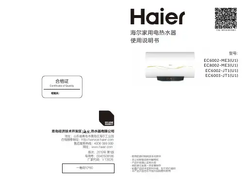
家用电热水器CEH-50A1(U1) CEH-60A1(U1) CEH-80A1(U1)智能家电操控智慧场景定制智家商城购物家电报装报修使用说明书使用前请仔细阅读本说明书本公司保留说明书解释权产品外观请以实物为准阅后请与发票一并妥善保存如遇产品技术或软件升级,恕不另行通知本产品只适合在中国大陆销售和使用带电监测多用途感受温暖舒适抛却劳累烦恼ENJOY WARMTH卡萨帝为了精确实现您的格调生活,对其家族每一类产品都赋予了专属的境界理念。
本产品为您带来的是舒适热水体验。
请仔细阅读本说明书来帮助您安全、舒适地使用产品。
为了能安全地使用产品,请在使用产品之前务必仔细阅读安全注意事项等内容。
1关于本产品的安全注意事项..........................................3-4外观及部件介绍 (5)技术数据 (5)电气原理图 (6)装箱单 (6)安装注意事项 (7)安装方法.......................................................................7-8机器预装步骤.............................................................................7-8安全阀排水管的连接 (8)使用注意事项 (9)本产品的主要功能介绍...............................................9-14控制屏 (9)使用方法..................................................................................9-13使用热水器的温馨提示 (14)本产品的日常保养与维护.........................................15-16热水器的清洁 (15)热水器的检查 (16)热水器的停用 (16)有疑问?先看这儿!.................................................17-18(若对热水器有疑问,请先按本章内容检查处理。
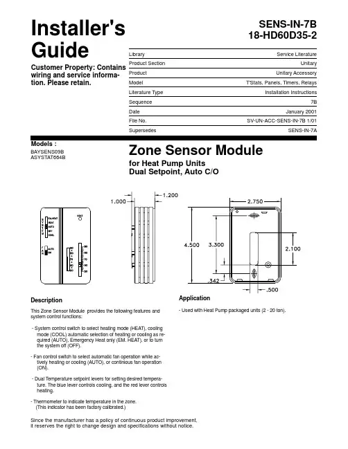
SENS-IN-7B 18-HD60D35-2LibraryService LiteratureProduct Section UnitaryProduct Unitary AccessoryModel T'Stats, Panels, Timers, RelaysLiterature Type Installation InstructionsSequence 7BDate January 2001File No.SV-UN-ACC-SENS-IN-7B 1/01SupersedesSENS-IN-7AZone Sensor Modulefor Heat Pump Units Dual Setpoint, Auto C/OBAYSENS09B ASYSTAT664BDescriptionThis Zone Sensor Module provides the following features and system control functions:- System control switch to select heating mode (HEAT), cooling mode (COOL) automatic selection of heating or cooling as re-quired (AUTO), Emergency Heat only (EM. HEAT), or to turn the system off (OFF).- Fan control switch to select automatic fan operation while ac-tively heating or cooling (AUTO), or continious fan operation (ON). - Dual Temperature setpoint levers for setting desired tempera-ture. The blue lever controls cooling, and the red lever controls heating.- Thermometer to indicate temperature in the zone. (This indicator has been factory calibrated.)Application- Used with Heat Pump packaged units (2 - 20 ton).Installer's GuideCustomer Property: Contains wiring and service informa-tion. Please retain.Models :Since the manufacturer has a policy of continuous product improvement,it reserves the right to change design and specifications without notice.InspectionCheck packaging and contents for damage. Check for concealed damage before storing. Report any damage immediately to the transportation company, and make any appropriate claims. Installation Steps1.Mounting location. Choose a spot on an interior wallnear the return air grille, about five feet above floor level,where air circulates freely and is of average tempera-ture for the zone.Avoid areas such as:- behind doors;- on outside walls, or any walls with unheated oruncooled areas behind the zone sensor;- in direct sunlight, or any source of radiant heat thatcould affect the temperature measurements; or- in line with the discharge air from the unit beingcontrolled.2. Mount subbase. Remove zone sensor cover from the sub-base, and mount subbase on the wall or in a 2 x 4 handy box.Route the wires through the wire access hole in the subbase.(See Figure 1) Seal the hole in the wall behind the subbase. Figure 1 - Zone Sensor Mounting (typical)Wiring!H A Z A R D O U S V O LTA G E!DISCONNECT ALL ELECTRIC POWER INCLUDING RE-MOTE DISCONNECTS BEFORE SERVICING.Failure to disconnect power before servicing can cause severe personal injury or death.Note: Guidelines for wire sizes and lengths are shown in Table 1.The total resistance of these low voltage wiresmust not exceed 2.5 ohms per conductor. Any resis-tance greater than 2.5 ohms may cause the control tomalfunction due to excessive voltage drop.Note: Do Not run low-voltage control wiring in sameconduit with high-voltage power wiring.1.Run wires. Run wires between the unit control paneland the zone sensor subbase. To determine the numberof wires required, refer to Unit IOM for Wiring Connections.2. Connect wires. Connect the wiring to the appropriateterminals at the unit control panel and at the ZoneSensor subbase. In general, zone sensor connections to the unit use the convention of connecting Zone Sensor terminals to like numbered Unit terminals (1 to 1, 2 to 2, etc.). The connec-tion detail is shown on the unit wiring diagrams which can be found in the unit service literature and on the unit.3. Replace cover. Place zone sensor cover back on thesubbase, snap securely into place.Table 1151 - 240 feet20 gauge241 - 385 feet18 gauge386 - 610 feet16 gauge611 - 970 feet14 gaugeOptional Remote Sensor (BAYSENS017)When using the optional remote sensor (BAYSENS017), mount it in the space that is to be controlled. Clip the thermistor (RT1) on the zone sensor module. Wire remote sensor to the zone sensor module according to the interconnecting wiring dia-grams in the unit's IOM.© American Standard Inc. 2001Technical Literature Printed in USA2。
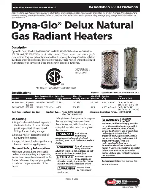
Unpacking1. Unpack all materials used to protect the heater inside of carton. Retain plastic caps attached to exposed fittings for use during storage.2. Remove heater, accessories and all hardware from carton.3. Inspect all items for damage that may have occurred during shipment.General Safety InformationMake sure you read and thoroughly understand these safety and operating instructions. Keep these instructions for future reference. They are your guides to safe and proper operation of this heater.Safety information appears throughout this manual. Pay close attention to them. Below are definitions for the safety information listed throughout this manual.Indicates an im m inen t lyhazardous situation which, if notavoided, WILL result in death or serious injury.Indicates a potentially hazardoussituation which, if not avoided, COULD result in death or serious injury.Indicates a potentially hazardoussitua t ion which, if not avoided, MAY result in minor or moderate injury.Consumer: Retain this manual for future reference.Dyna-Glo ®Delux Natural Gas Radiant HeatersPlease read and save these instructions. Read carefully before attempting to assemble, install, operate or maintain the product described. Protect yourself and others by observing all safety information. Failure to comply with instructions could result in personal injury and/or property damage! Retain instructions for future reference.DescriptionDyna-Glo Delux Models RA100NGDGD and RA250NGDGD heaters are 50,000 to 100,000 and 250,000 BTU/Hr construction heaters. These heaters use natural gas for combustion. They are primarily intended for temporary heating of well-ventilated buildings under construction, alteration or repair. These heaters should be utilized in sheltered, well-ventilated areas, but never in occupied dwellings.Ignitor SizeGapL x W x H (in.)RA100NGDGD 50,000 to 104 ft 3/hr (2.95 m 3/h) 8” W.C. 14” W.C.7.5” W.C. 0.19“ (4.8mm) 16.3 x 16.3 x 29.8 100,000(41.4 x 41.4 x 75.7 cm)RA250NGDGD 250,000 260 ft 3/h (7.36 m 3/h) 10 PSI 250 PSI6 PSI 0.19” (4.8 mm) 14.7 x 14.7 x 44.3 (37.3 x 37.3 x 112.5 cm)Fuel Type – Natural Gas Only Ignition Type – P iezo (RA100NGDGD)Minimum Operating Temp. – -20°F (-29°C)Pilot (RA250NGDGD)SpecificationsGHP Group, Inc.6440 W Howard St Niles, IL 60714ANS Z83.7-2011 CSA 2.14-2011 Construction HeaterC USC USFigure 1 – Models RA100NGDGD / RA250NGDGDGeneral Safety Informationconstruction heater in accordance with ANS Z83.7 CSA 2.14. Other standards govern the use of fuel gases and heating products for specific uses. Your local authority can inform you of these. The primary purpose of these construction heaters are to provide temporaryheating of building under construction, alteration, or repair. When properlyused, the heater provides safe economical heating. Products of combustion are vented into the heated area.- For either indoor or outdoor use. Adequate ventilation must be provided.IMPORTANT: Every possible circum-stance that might involve a hazard can-not be anticipated. The warnings in this manual on tags or decals affixed to the unit are not all inclusive. If a procedure,work method, or operating technique not specifically recommended by Day-ton is used, you must make sure it is safe for you and others. You should also ensure that equipment will not be dam-aged or be made unsafe by the operat-ing or maintenance method you use.death! Some people are more affected by Carbon Monoxide than others. Early signs of carbon monoxide poisoning resemble the flu, with headaches, dizziness, and/or nausea. If you have these signs, theheater may not be operating properly or the area may not be sufficientlyventilated. Get fresh air at once! Have heater serviced.Carefully install and always use great carewhen operating this heater. Be sure to research and follow all local ordinances and codes. In the absence of local codes, with the Standard for the Storage and Handling of Liquefied Petroleum Gases, ANSI/NFPA 58 and the Natural Gas and Propane Installation Code CSA B149.1.Natural Gas: Natural gas has a very distinctive odor that will help you detect a leak. However, this odor may fade in time. Natural gas may be present in the area even though no odor is detected.– U se only natural gas. Do not attempt to use propane gas. Use only factory preset regulator provided on heater.– P rovide adequate ventilation. Before using heater, provide at least a 3square foot (.28 m 2) opening of fresh, outside air for every 100,000 BTU/Hr rating.CaliforniaProposition 65Warning: Fuels used in gas or oil fired appliances and the products of combustion of such fuels, contain chemicals known to the State ofCalifornia to cause cancer, birth defects or other reproductive harm. This product contains chemicals, including lead and lead compounds, known to the state ofCalifornia to cause cancer, birth defects or other reproductive harm. Wash hands after handling.– T his heater should be utilized in sheltered, well-ventilated areas, but never in occupied dwellings.– D o not use heater in occupieddwellings, in living or sleeping areas.– K eep appliance clear and free from combustible materials, gasoline, paint thinner, and other flammable vapors and liquids. Dust is combustible. Do not use heaters in areas with high dust content.– C heck heater for damage before each use. Do not use damaged heater.®Radiant HeatersGeneral Safety Information (Continued)Minimum heater clearance from combustibles:Sides: 6 feet (1.8 m) Top: 5 feet (1.5 m)Floor: Combustible - Not for use on finished floors– T he heater, other than a heater with integral propane gas container, must be located at least 6 feet (1.8 m) (in Canada, distance must be 10 feet [3 m]) from any propane gas container.– B lower or radiant type heaters shall not be directed toward any propane gas container within 20 feet (6 m).– C heck hose before each use of heater. Do not use if hose is cut or damaged. Replace with hose specified by manufacturer.– A lways be sure to place the heater onheater is in operation.– T damage may occur.– P water or rain.– K from the heater.– N – A lways wear gloves when handling the heater to prevent injury.– N ever attach ductwork to heater.– D o not alter heater. Keep heater in its original state.– D o not use heater if altered.– T urn off gas supply to heater whennot in use.– U se only original replacement parts.This heater must use design specific parts. Do not substitute or use generic parts. Improper replacement parts could cause serious or fatal injury.AssemblyMODEL RA100NGDGD1. Provide natural gas supply system.2. Install plumbing to a low pressure natural gas source to heater. The source must be regulated to 1/2 PSI, maximum 3/4’’ (19 mm) I.D. pipe or flexible connector, not longer than 10 feet (3 m).3. Be sure to use thread sealingcompound when connecting the hose to the heater at the 1/2’’ (13 mm) NPT fitting at the regulator inlet. Tighten all fittings with a wrench.4. Open natural gas supply valve Never use an open flame to check for aleak. Apply 50/50 mixture of liquid soap and water to all joints. Bubbles forming show a leak. Correct all leaks at once.6. Close natural gas supply valve.MODEL RA250NGDGD1. Insert AA battery (included) into ignition by turning COUNTERCLOCKWISE and unscrewing ignition cap.2. Provide natural gas supply system.3. Install plumbing to a natural gas source to heater.4. Connect gas supply to heater using minimum 3/8” (10 mm) ID pipe.Maximum pipe length is 10 feet (3 m).5. Connect hose or plumbing to 1/2” (13 mm) NPT flare fitting at thevalve inlet. Tighten all fittings with a wrench.6. Open natural gas supply valveSLOWLY. Check all connections for leaks. Never use an open flame to check for leaks.7. Close natural gas supply valve. NOTE: Keep hands and face away from outlet (around top of shelf) of heater while attempting to start heater.Models RA100NGDGD and RA250NGDGDDyna-Glo Delux Operating Instructions and Parts ManualFigure 3 – Heater Control Knob –RA100NGDGDHot while inoperation. Do nottouch. Keep children, clothing, furniture,gasoline, and other liquids havingflammable vapors away.The gas supply attaches to the heaterby a minimum 3/8’’ (10 mm) I.D. pipeor flexible connector. User must supplypipe or flexible connector. The lengthshould be no more than 10 feet (3 m).The natural gas moves through the2. Always be sure to place the heater ona stable and level surface while theheater is in operation. Be sure that nostrong winds blow into the ends ofthe heater.to OFF position.4. Turn natural gas supply valve on.5. Depress heater control knob andturn counterclockwise to (IGN) LOWTO SHUT DOWN HEATER1. Shut off the main burner valve, beingsure to wear a glove for protection.Turn the control knob to the OFFposition.2. Firmly close the natural gas supplyvalve.TO RESTART HEATER1. Wait five minutes for heater to cool.2. Follow steps in TO START HEATERsection.TO START HEATER (RA250NGDGD)1. Follow all of the safety, ventilationand installation instructionspreviously noted in this manual.2. Always be sure to place the heater ona stable and level surface while theheater is in operation. Be sure that nostrong winds blow into the ends ofthe heater.3. SLOWLY open the gas valve.4. Push in and hold safety valve buttonwhile pushing ignitor button untilpilot lights (see Figure 4).NOTE: Hose may be filled with air, ifso, allow around 15 seconds for gas toreach pilot.5. If pilot does not light, repeat Step 4.6. When pilot stays lit, fully open themain burner valve by turning thehandle of the burner valve counter-clockwise until it stops all the way tothe ON position.®Radiant HeatersFigure 4 – RA250NGDGD Part IdentificationOperation (Continued) NOTE: Arrows on main burner valve handle show directions for ON and OFF.TO SHUT DOWN HEATER1. Firmly close the natural gas supply valve.2. Shut off the main burner valve, being sure to wear a glove for protection.the way to the OFF position.TO RESTART HEATER1. Wait five minutes for heater to cool.2. Follow steps in TO START HEATERsection.Running heaterbelow specified gaspressure may cause flashback. Duringflashback, the burner flame is mostlyyellow. The flame will burn inside theburner tube causing a roaring noise. Ifflashback occurs, turn heater off. Afterburner tube cools off, restart heater.NATURAL GAS SUPPLYYou must provide the natural gas supplyalong with all pipe and fittings.Check with your local gas supplier toproperly size all of your supply lines. Besure to follow all local codes, or refer tothe Natural Fuel Gas Code Handbook –NFPA54/ANSI Z223.1, or the Natural GasInstallation Code – CAN/CSA B149.1.VENTILATIONA three square footopening of freshoutside air for each 100,000 BTU/Hr ofheater output must be provided tooperate each heater safely. If the properventilation air is not provided, carbonmonoxide poisoning can occur.Always be sure that the properventilation is being provided beforestarting this heater.FRESH OUTSIDE AIR OPENINGREQUIREMENTSHeater size Opening100,000 BTU 3.0 ft2 (.28 m2)250,000 BTU 7.5 ft2 (.70 m2)Read and understandall of the warnings inthe General Safety Information pages of thismanual. They are essential to the safeoperation of this heater. Be sure to followall local codes when operating this heater.Be sure to leak test allfittings and pipeconnections after installation or repairs. Usea 50/50 mixture of liquid dish soap andwater. Bubbles forming reveal a leak. Youmust repair all leaks at once!Models RA100NGDGD and RA250NGDGD Dyna-Glo Delux Operating Instructions and Parts ManualFigure 5 – RA100NGDGD Part IdentificationKnobNever attempt toservice heater whileit is connected to natural gas supply,operating, or hot. Severe burns can occur.1. Always keep heater clean.2. Inspect heater before each use.Check connections for leaks. Applya 50/50 solution of dish soap andwater. Bubbles forming show a leakthat must be corrected. Correct leaksat once.3. Inspect regulator hose assemblybefore each use. If hose is highlyworn or cut, replace with hosespecified by manufacturer.4. Keep appliance area clear and freefrom combustible materials, gasoline,and other flammable vapors andliquids.5. Have heater inspected yearly by aqualified service person.6. The flow of combustion andventilation air cannot be obstructed.STORAGEDisconnect heaterfrom natural gassupply.1. Place plastic cover over brass fittingon inlet connector.2. Store in a dry, clean, safe place.3. When taking the heater out ofstorage, always check inside theheater. Small animals or insects mayplace foreign objects in the heater.Keep heater free from foreign objectsand combustible materials.®Radiant HeatersSymptom Possible Cause(s) Corrective ActionBurner fails to lightBurner lights but goes outwhen automatic controlvalve button is releasedBurn rate is low, emitterdoes not glowFlames are extremely highand coming from emitter1. More warm-up time needed2. Gas pressure is low3. Thermocouple loose or in need ofreplacement4. Automatic control valve in need ofreplacement1. Main burner valve not completely open2. Clogged gas orifice3. Low gas pressure4. Low gas supply1. Main burner valve not fully open2. Plugged gas orifices3. Low gas pressure4. Low fuel supplyUnit has been connected to a propane gassupply instead of natural gas1. Relight, holding control valve button in for45 seconds2. Inspect natural gas supply3. Tighten, reconnect or replacethermocouple4. Replace automatic control valve1. Completely open main burner valve byturning control knob to HIGH position2. Replace gas orifice3. Check gas supply, regulator function4. Contact gas supplier1. Fully open main burner valve by turningcontrol knob towards HIGH position until itstops2. Replace gas orifice3. Check gas supply, regulator output4. Consult gas supplierCheck gas source and replace with natural gassupplyTroubleshooting ChartFor Repair Parts, call 1-877-447-4768 Please provide following information:-Model number-Serial number (if any)-Part description and number as shown in parts list ArrayFigure 6 – Repair Parts Illustration for Natural Gas Radiant Heater RA100NGDGDModel RA100NGDGDDyna-Glo Delux Operating Instructions and Parts ManualRepair Parts List for Natural Gas Radiant Heater RA100NGDGD1 Top Cover 5002854 12 Guard 2315528 13 Emitter 2315519 14 N ozzle2315521 1 5 Nozzle Connector 2315545 1 6 Nozzle Nut2315546 1 7 Main Gas Tubing Assy (NG) 2315523 1 8 Nozzle Bracket 2315517 1 9 Flame Shield 2315516 2 10 Thermocouple 2201584 1 11 Spark Plug2201583 1 12 Thermocouple Holder 2315520 1 13 Base5002851 1 14 Control Knob 2101451 1 15 Control Valve GS22 (8B) 1 16 Fitting2304948 2 17 Tubing Inlet Assy2315524 1 18 Fitting-Regulator to Tubing Inlet 2315547 1 19 Regulator2315555 1 20 Regulator Bracket 2315518 1ReferenceNumber DescriptionRA100NGDGDQuantityHeater must use designspecific parts. Do not substitute or use generic parts. Improper replacement parts could cause serious or fatal injuries.Figure 7 – Repair Parts Illustration for Natural Gas Radiant Heater RA250NGDGDFor Repair Parts, call 1-877-447-4768Please provide following information:-Model numberModel RA250NGDGDDyna-Glo Delux Operating Instructions and Parts ManualRepair Parts List for Natural Gas Radiant Heater RA250NGDGD1 Top Cover 5002854 12 Guard 2315554 13 Emitter 2315537 14 Upper Base 5002853 15 Base Cover 2315532 16 Lead Wire 2315643 17 Tilt Switch 2300186 18 Lower Base 5002852 19 Blanket 2315539 1 10 Insulation 2315544 1 11 Flame Shield 2315540 1 12 Thermocouple 2201591 1 13 Spark Plug2201583 1 14 Spark Plug Bracket 2315609 1 15 Bracket2315520 1 16 Box for Lead Wire 2315535 1 17 Pilot Assy GL250.39 1 18 Pilot Bracket 2315608 1 19 Wind Box 2315610 1 20 Ignition Wire 2201585 1 21 Battery 2300481 1 22 Ignition 2201220 1 23 Regulator2315513 1 24 Regulator Holder 2315536 1 25 Regulator Connector 2315547 1 26 Inlet Tubing Assy 2315542 1 27 Connector 2315549 1 28 Control ValveGS16 1 29 Contol Valve Fixing Nut 2305687 1 30 Contol Valve Bracket 2315538 1 31 Ball ValveGQ01 1 32 Ball Valve Connector 2305391 1 33 Pilot Connector 2315548 1 34 Main Tubing Assy 2315550 1 35 Pilot Tubing 2001402 1 36 Base Shield2315541 1 37 Rubber Ring for Wire 2315543 1 38 Nozzle Bracket 2315533 1 39 Nut2101008 1 40 Nozzle Connector 2315534 1 41 Nozzle 2315546 1Reference Number DescriptionRA250NGDGDQuantityHeater must use designspecific parts. Do not substitute or use generic parts. Improper replacement parts could cause serious or fatal injuries.WarrantyRA100NGDGD and RA250NGDGD Dyna-Glo Delux Operating Instructions and Parts ManualLIMITED WARRANTY:This limited warranty is extended to the original retail purchaser of this Forced Air/Convection/Radiant Heater and warrants against anydefect in materials and workmanship for a period of one (1) year from the date of retail sale. GHP Group, Inc., at it’s option, will eitherprovide replacement parts or replace or repair the unit, when properly returned to the retailer where purchased or one of our service centersas directed by GHP Group, Inc., within one (1) year of retail purchase. (Shipping costs, labour costs, etc. are the responsibility of the purchaser.)DUTIES OF THE OWNER:This heating appliance must be operated in accordance with the written instructions furnished with this heater.This warranty shall not excusethe owner from properly maintaining this heater in accordance with the written instructions furnished with this heater.A bill of sale,canceledcheck or payment record must be kept to verify purchase date and establish warranty period.Original carton should be kept in case of warrantyreturn of unit.WHAT IS NOT COVERED:1.Damage resulting from use of improper fuel.2.Damage caused by misuse or use contrary to the owners manual and safety guidelines.3.Damage caused by a lack of normal maintenance.4.Fusese of non-standard parts or accessories.6.Damage caused in transit.Freight charges on warranty parts or heaters to and from the factory shall be the responsibility of the owner.This warranty does not imply or assume any responsibility for consequential damages that may result from the use,misuse,or the lack ofroutine maintenance of this heating appliance.A cleaning fee and the cost of parts may be charged for appliance failures resulting from lack ofmaintenance.This warranty does not cover claims which do not involve defective workmanship or materials.FAILURE TO PERFORMGENERAL MAINTENANCE(INCLUDING CLEANING)WILL VOID THIS WARRANTY.THIS LIMITED WARRANTY IS GIVEN TO THE PURCHASER IN LIEU OF ALL OTHER WARRANTIES,EXPRESSED OR IMPLIED,INCLUDING BUT NOT LIMITED TO THE WARRANTIES OF MERCHANTABILITY OF FITNESS FOR A PARTICULAR PURPOSE.THEREMEDY PROVIDED IN THIS WARRANTY IS EXCLUSIVE AND IS GRANTED IN LIEU OF ALL OTHER REMEDIES.IN NO EVENT WILLGHP GROUP, INC. BE LIABLE FOR INCIDENTAL OR CONSEQUENTIAL DAMAGES.Some states do not allow limitations on how long an implied warranty lasts,so the above limitation may not apply to you.Some states do notallow the exclusion or limitation of incidental or consequential damages so the above limitation or exclusion may not apply to you.CLAIMS HANDLED AS FOLLOWS:1.Contact your retailer and explain the problem.2.If the retailer is unable to resolve the problem,contact ourCustomer Service Dept.detailing the heater model,the problem,and proofof date of purchase.3.A representative will contact you.DO NOT RETURN THE HEATER TO GHP GROUP,INC.unless instructed by our Representative.This warranty gives you specific legal rights and you may also have other rights which vary from state to state.TO REGISTER THE WARRANTY ON YOUR HEATER,PLEASE FILL OUT THIS CARD COMPLETELYAND MAIL WITHIN14DAYS FROM DATE OF PURCHASE OR REGISTER ON-LINE AT NAME:______________________________________PHONE:()__________________EMAIL:____________________________ADDRESS:_________________________________CITY:______________________________STATE:__________ZIP:____________MODEL:____________________SERIAL#:_______________________________________DATE PURCHASED:__________________DEALER PURCHASED FROM:____________________________________________TYPE OF STORE:__________________________CITY&STATE WHERE PURCHASED:______________________________________________PRICE PAID:_______________________Please Take a Minute To Give Us Your Answers To The Following Questions.All Responses Are Used Solely For Market Research And Are Held In Strict Confidence.Who primarily decided this purchase?Male Female18-2425-3940-5960and overPurpose of Purchase?_______________________________________________________________________________________________Do you own any other portable heaters?Yes No If yes,type____________________________brand_____________________How do you intend to use your new heater?Construction Site Farm Warehouse/Commercial Garage/Outbuilding OtherHow did you become aware of this heater?In-Store Display Newspaper Ad Magazine Ad Friend/RelativeTV Commercial Store Salesperson Other___________________________What made you select this heater?Style Size/Portability Price Package Brand Other___________________Do you:own rent Would you recommend this heater to a friend?Yes NoPlease give us your comments:________________________________________________________________________________________THANK YOU FOR COMPLETING THIS FORM!Information will be held confidential.WARRANTY REGISTRATIONIMPORTANT:We urge you to fill out your warranty registration card within fourteen (14)days of date of purchase.You can also register your warranty on the internet atplete the entire serial number.Retain this portion of the card for your records.SAVE THIS CARD!Place Postage Stamp Here Tel: (877) GHP Group, Inc.6440 W Howard St Niles, IL 60714-3302GHP Group, Inc.6440 W Howard StNiles, IL 60714-3302。
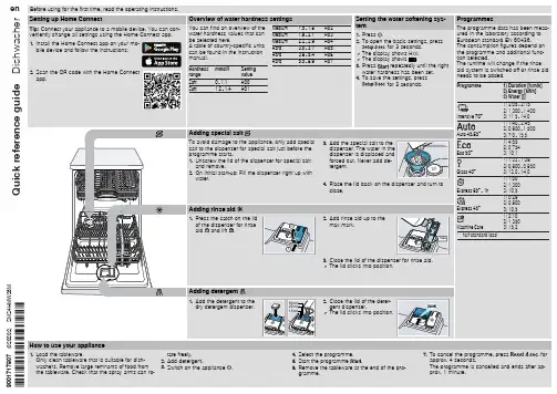
ES50H-CK3(1)使用说明
1、插上电源,按下电热水器的开关按钮,同时设置一下水温。
一般情况下,我都设置在45度,冬天的话,温度可以相对地调高一点。
2、等水烧开了之后,先把阀门调至中间位置,放会水,试下水温不凉了再开始使用。
(一般阀门左侧标有H字样是热水,右侧标有C是冷水。
热水显示红色标识,冷水显示蓝色表示。
)
3、等水温恒定了之后可以使用,因为电热水器四周都是水,很容易触电,所以,在使用过程中尽量不要用手或者其它部位触碰其它地方,尤其是电源周围。
4、使用电热水器时,当打开水阀而没有出水时,要立即断开电源,防止因故障使电热水器在无流动水的情况下工作而损坏。
5、如果水压或电压过低,应暂停使用。
6、使用完毕后,先关闭电热水器上的开关,等手擦干之后,再拔掉电源。
6 规格·装箱单 1 安全警告(使用前请先阅读)技术数据外观及部件介绍装箱单检查电表,电线直径是否符合热水器的额定电流,必要时请有资质的电工师傅检查一下。
该热水器使用交流220V/50Hz电源,使用独立插座(禁止使用多功能插座)并进行可靠接地,严禁在无可靠接地的情况下使用热水器。
请不要使用受损的电源线和电源插座及插头十分松弛的电器产品。
否则会引起触电、短路、火灾等事故。
应该确认电源插头能够与电源插座严密结合。
插座质量要符合国家标准,并且要及时擦拭电源插头上的金属片,防止金属片上沾有污渍而引起火灾等事故。
安装好后,首次使用必须先注满水后再接通电源。
若在容器水不满的情况下通电,加热管过热会造成故障。
寒冷地区冬季若长期不使用请将水排空以防结冰损坏热水器(详见使用注意事项)。
热水器电源插座应安置在水喷淋不到的干燥处,请勿湿手插拔电源插头。
否则会出现触电、受伤等事故。
当电热水器被水严重浸湿后,再次使用前须经本公司认可的技术人员检验。
如果电热水器的电源线损坏,必须由售后人员用专用线缆进行更换(厂家提供)。
除专门技术维修人员外其他人不得拆卸、维修。
此不要放置在太冷能够结冰的环境中,如果结冰,容器和水管就会破裂,造成烫伤和漏水。
不要安装在室外。
不要落地安装。
应挂于坚实、牢固的墙壁上。
不要安装在无法排水的地方。
若连接排水管,应将排水管接于下水道口处,以免将室内溅污。
检查电表、电线电源线及插座要求机器使用前长期不使用热水器时采用220V/50Hz交流电源当电源线损坏时放置环境外不要将汽油等易燃物品放置在热水器附近,否则可能会引起火灾。
关于机配管路的使用注意防水本产品的机配管路是“防电墙”产品的有机组成部分,切勿随意拆除,否则由此带来的安全隐患所造成的伤害,本公司不予承担。
电气原理图ES6.6 ES6.6U额定电压:220V50H z~,外形尺寸:(参见图)一功率:1500W净重: (参见图)一额定压力:0.75 M Pa容量:(参见图)一额定温度:℃75自来水压力:不低于0.05M P a防水等级:IP X4注:ES6.6电热水器,不随机配备电源开关,如需使用,请联系海尔售后人员进行购买。
ES40H-J1(E) ES50H-J1(E) ES60H-J1(E)ES40H-GZ1(1)ES50H-GZ1(1)ES60H-GZ1(1)
本标识是海尔热水器公司“安全预警”专用标识,内部使用了本公司的专利技术(ZL01135300.7),在确保您安全洗浴的同时,时刻监测您家庭的地线是否带电。
如本标识点亮,则表示您家的地线已经带电,应即刻停止使用并
拔掉电源插头,同时切记不要触及家中任何电器的外壳,并马上联系售后部门(售后服务电话:4006 999 999)或物业公司,由专业电工进行系统检测直至本标识熄灭。
务必使用220V/50Hz的独立电源。
为了确保安全,热水器应使用独立插座(禁止使用多功能插座),并进行可靠接地,且插座质量应符合国家标准,严禁在无可靠接地的情况下使用热水器。
用测电笔测量火线、零线是否接反。
由于此款电热水器功率较大,为保证本机的正常工作及家庭的用电安全,建议您在安装时采用与本机插头(16A)相匹配的电源插座。
型号:
扫描二维码 智享科技魅力
使用前请仔细阅读本说明书本公司保留说明书解释权产品外观请以实物为准阅后请与发票一并妥善保存
如遇产品技术或软件升级,恕不另行通知本产品只适合在中国大陆销售和使用该系列电热水器执行国家标准:
GB4706.12-2006《家用和类似用途电器的安全 储水式热水器的特殊要求》
版次:2018年 第2版 专用号:0040506632 厂家代码:V 98497
地址:青岛经济技术开发区海尔工业园在线报修地址: 售后服务热线:4006 999 999 网址:
青岛经济技术开发区 热水器有限公司。