微波车流量检测器用户手册
- 格式:doc
- 大小:1.84 MB
- 文档页数:24

Flo-Tech, PFM6 流量压力检测仪使用说明书流量压力检测仪的使用要领1. 检测仪各部名称(图1)涡轮流量计各部名称(图2)2. Flo-tech检测仪参数* 为现用检测仪(1) 检测仪使用要点本检测仪操作简单,不需要特殊练习,就可以立刻使用。
为了正确的判断试验结果,有必要事先了解测试对象的液压系统和各液压执行部件,掌握必要的资料,比如:操作压力、流量、溢流阀设定压力、液压泵的最高输出压力、液压泵的性能曲线等。
①液压软管的连接检测仪如上表所示有三种机型,其软管的连接分两种类型a、PFM6-50、PFM6-85为1英寸的PT内螺纹。
b、PFM6-200上附有1英寸PT螺纹的连接器。
90°的管接头、T型管接头、阀等距离检测仪的输入端最好在30cm以上,因为这些部件将会给流体的测量带来误差。
软管的另一侧(与被测机器连接侧)通常与连接检测仪一侧为相同连接螺母,所以当管径或螺纹不同时,请利用转接器。
②操作要领检测仪的操作是简单的,但误操作将会给检测仪或被测试机器、回路带来不良影响。
使用者在使用前请读熟本使用说明书,避免误操作,以提高测试效率。
a、转换开关通常在中央位置(OFF)测试流量时请放在(FLOW)档位测试油温时请放在(TEMP)档位测试结束后,请勿必将开关拨回到OFF位置。
干电池使用过期电压下降时,仪表(流量、温度计上的冒号:)将发生闪烁。
此时,请更换干电池。
b、认真确认软管是否已正确无误地连接在检测仪的输入、输出端。
检测仪可以并列接入高压侧,但流向若是接反则不能测量正确的流量。
c、液压回路动作前,应将加载阀反时针方向旋转打开。
d、加载阀可以用手简单地进行操作,在加压和卸压时,请缓慢地进行操作。
e、液压回路动作停止之前,要将加载阀打开,确认压力是否已降到零。
在进行多项压力测试时,每一次测试结束,也都应该将加载阀先打开,然后进行下一个项目的测试。
f、安全圆片是保护检测仪和液压机器的,测试时,请密切注意压力表的读数,使之不要超过回路的最高压力。
吸顶式微波探测器用户手册(485型)VMS-300XD2-WB/HWB-N01Ver1.0目录1.产品简介 (3)1.1产品概述 (3)1.2主要技术指标 (3)1.3功能特点 (3)1.4产品选型 (4)1.5系统框架图 (4)1.6产品外观 (5)3.安装与使用说明 (6)3.1设备安装前检查 (6)3.2接线说明 (6)3.3安装说明 (6)3.4使用说明 (7)3.5检测范围图 (7)4.配置软件安装及使用 (7)4.1软件选择 (7)4.2参数设置 (7)5.通信协议 (8)5.1通讯基本参数 (8)5.2数据帧格式定义 (8)5.3寄存器地址 (9)5.4通讯协议示例以及解释 (9)6.常见问题及解决办法 (10)1.产品简介1.1产品概述此设备为高稳定性雷达微波探测器。
采用先进的信号分析处理技术,具有超高的探测和防误报性能。
当有入侵者通过探测区域时,探测器将自动探测区域内人体的活动。
如有动态移动现象,则会产生报警,设备为485输出,标准的ModBus-RTU协议,可二次开发。
产品适合家庭住宅区、楼盘别墅、厂房、仓库、商场、写字楼等场所的安全防范。
1.2主要技术指标■供电电源:10~30V DC■功耗:0.3W■传感器类型:微波传感器■报警延时:0-65535s可调(报警持续时间)■延时报警:软件设置(发生报警的延时)■工作频率:24.00~24.25GHz■安装方式:吸顶■安装高度:2.5~6m■探测范围:直径6m(安装高度3.6m时)■探测角度:全方位360°■信号输出:RS485■通信协议:ModBus-RTU■工作环境:-10℃~50℃,≤95%RH(非结露)1.3功能特点■采用8-bit低功耗CMOS处理器■具有自动温度补偿功能■抗RFI干扰:20~1000MHz(如移动通信)■三种报警延时输出可选设备尺寸:1.4产品选型VMS-公司代号300XD2-新款吸顶外壳HW-红外报警器WB-微波报警器HWB-红外微波双鉴报警器N01485通讯(ModBus协议)1.5系统框架图本产品也可以多个传感器组合在一条485总线使用,理论上一条总线可以254个485传感器,另一端接入带有485接口的PLC、通过485接口芯片连接单片机,或者使用USB 转485即可与电脑连接,使用我公司提供的传感器配置工具进行配置和测试(在使用该配置软件时只能接一台设备)。
远程交通微波雷达检测器(RTMS)的深度解析知识讲解远程交通微波雷达检测器(RTMS),这可是个在交通检测领域相当厉害的家伙呢。
RTMS就像是交通世界里的超级侦探。
它在那里默默坚守岗位,眼睛一刻不停地盯着马路上的各种动静。
它是怎么做到的呢?这就不得不说它的微波探测技术啦。
就好比蝙蝠用超声波来探测周围环境一样,RTMS利用微波去感知车辆的存在。
它发出微波信号,这些信号遇到车辆就会反射回来,然后它就根据反射回来的信号知道车辆的位置、速度等各种信息。
这RTMS啊,它检测速度的本事可大了。
它能精确地算出车辆的行驶速度,就像一个数学天才,眼睛一扫就能得出答案。
它不是那种只能大概估计的,而是相当准确的哦。
比如说在高速公路上,车辆来来往往,速度有快有慢,RTMS就稳稳地在那里,把每辆车的速度都摸得清清楚楚。
要是有车辆超速了,它就像是一个严厉的交通警察,虽然不能直接开罚单,但是可以把超速信息传递给相关部门,让那些超速的家伙无处遁形。
再说说它检测车流量的能力吧。
想象一下,马路上的车辆就像一群蚂蚁在搬家,密密麻麻的。
RTMS呢,就像一个耐心的计数员,一辆一辆地数着过往的车辆。
不管是白天车水马龙的时候,还是晚上车辆稀少的时候,它都不会数错。
它能准确地知道在一定时间内有多少辆车通过了某个路段。
这对于交通规划者来说,就像是得到了一本宝典。
他们可以根据这些数据来决定是不是要拓宽道路,或者调整交通信号灯的时间。
RTMS的安装位置也很有讲究。
它不能随便找个地方就安上,就像人找房子得找个合适的地方住一样。
一般来说,它会被安装在路边的杆子上或者天桥上,要确保它的视野开阔,能够清楚地看到需要检测的路段。
如果安装的位置不对,就好比一个人站在墙角想看清整个房间一样,那是根本做不到的。
它得能毫无阻碍地发出微波信号,并且接收反射回来的信号才行。
而且啊,RTMS还有很强的适应能力。
不管是晴天还是雨天,不管是炎热的夏天还是寒冷的冬天,它都能正常工作。
佰誉达车流量检测雷达(本产品已通过国家道路交通安全产品质量监督检验中心公安部交通安全产品质量监督检测中心认证)用户手册佰誉达科技深圳目录一、微波车流量检测雷达概述 (1)1.1用途 (1)1.2描述 (1)1.3技术指标 (2)1.3.1微波指标 (2)1.3.2检测指标 (2)1.3.3通信指标 (3)1.3.4环境与可靠性指标 (3)1.3.5电源指标 (3)1.3.6物理指标 (3)1.4应用领域 (3)1.4.1路口模式(城市交通) (3)1.4.2高速公路(城市交通、高速公路) (4)1.5典型应用 (4)1.5.1路口模式(城市交通) (4)1.5.2路段模式(城市交通、高速公路) (5)二、微波车流量检测雷达的安装 (7)2.1设备组成 (7)2.2设备安装 (7)2.3工程安装 (8)2.4雷达接口 (8)三、微波车流量检测雷达的调试及使用 (9)3.1软件运行环境 (9)3.2软件安装 (9)3.3软件使用说明 (9)3.3.1主界面 (9)3.3.2 设备参数 (10)3.3.3雷达参数 (10)3.3.4 安装参数 (11)3.3.5 连接雷达 (12)3.3.6按钮功能说明 (12)3.3.7 车道计数 (13)3.3.8 车道流量统计直方图 (13)四、微波车流量检测雷达数据传输 (13)4.1雷达数据传输模式 (13)五、微波车流量检测雷达故障排除 (14)附录1 (14)一、微波车流量检测雷达概述1.1用途车流量检测雷达是拥有完全自主知识产权的新型微波车辆检测器,利用雷达线性调频技术原理,对路面发射微波,通过对回波信号进行高速实时的数字化处理分析,检测车流量、速度、车道占有率和车型等交通流基本信息的非接触式交通检测器。
检测器主要应用于高速公路、城市快速路、普通公路交通流量调查站和桥梁的交通参数采集,为交通管理提供准确、可靠、实时的交通情报,为实现交通智能化提供技术支持。
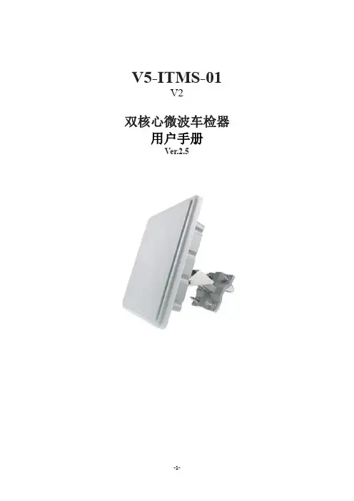
V5-ITMS-01V2双核心微波车检器用户手册Ver.2.51.产品简介 (4)2.功能特点 (4)2.1 数据采集和参数设置 (5)2.2 复原能力 (5)2.3 本地操作与自检维护 (5)2.4 控制功能 (5)2.5 其它 (5)3.产品指标 (6)3.1 微波指标 (6)3.2 检测指标 (6)3.3 通信指标 (6)3.4 环境与可靠度指标 (6)3.5 电源指标 (6)3.6 设备指标 (6)4.认证 (6)5.设备安装 (7)5.1 典型设置 (7)5.2 环境选择 (7)5.3 安装高度、角度 (8)5.3.1 侧置距离与安装高度关系对照表 (9)5.3.2 侧置距离与安装高度选用之概测方法 (9)5.4 安装程序 (9)5.4.1 设备组件 (9)5.4.2 安装流程 (9)6.设备调试.................................... . (11)6.1 连接设定 (11)6.2 调试软件与设备连接 (12)6.3 调试软件(GUI)使用说明 (13)6.3.1 基本功能及字段使用说明 (13)6.3.2 弹出式子菜单使用说明 (17)6.4 调试操作流程 (19)6.5 准确度验测 (21)6.6 测试记录文件 (21)6.6.1 统计资料 (21)6.6.2 单车资料 (22)7.设备维护.................................... . (23)7.1 固件版本更新 (23)7.2 设备初步功能简昜检测 (24)7.3 软件故障排查 (26)8.传输缆线 (27)8.1 接线协议 (27)8.2 接线说明 (27)9.维护与服务 (28)9.1 硬件维护需知 (28)9.2 设备识别 (28)9.3 维修运送 (28)9.4 质保 (28)9.5 手册编修日期 (28)附录1:V5-ITMS-01 V2双核心微波车检器故障排查 (29)附录2:微波车检器安装调试记录表 (30)附录3:微波车检器设备失效记录表 (31)1.产品简介V5-ITMS-01 V2为运用调频连续波(FMCW)目标侦测技术之非接触式微波雷达车辆检侧器, 采用最新自主知识产权微波技术,融合双核心数字运算器,兼容侦测、演算与通讯于单一处理器模块。

微波交通检测器应用方案——T-11 V5 多目标追踪雷达江苏志德华通信息技术有限公司编辑者:高志鹏1.Tracteh T-11 V5多目标追踪微波车辆检测器简介1.1功能概述●Tractech T-11 V5多目标追踪微波车辆检测器(以下简称T-11 V5),是利用二维主动扫描式阵列雷达微波检测技术,对路面发射微波,以每秒20次的扫描频率可靠地检测路上每一车道的目标,准确区分机动力、非机动力、行人等,可同时识别及跟踪最多64个目标对象。
●可同时测量每车道的流量、平均速度、占有率、85%位速率、车头时距、车间距等交通数据,以及排队长度、逆行、超速、ETA等报警信息,并可准确地测量区域内每个目标的位置坐标(X,Y)与速度(Vx, Vy)。
●能进行大区域检测,沿来车方向正常检测区域至少可达160米,能同时检测至少6个车道,其中中间的4个车道每条车道可以有4个精确的检测点,4条车道就可以配置16个精确的检测点。
每个检测点就是一条线,这条线与路交叉成90度夹角,也就是垂直于路的方向。
这些垂直于路的方向的检测线,就可以作为雷达的检测点,可以非常精确检测车辆接近并经过这些检测点时的状态●自动检测交通流的运行方向,进行车辆逆行检测统计。
●采用前向安装的方式,可方便地利用既有杆件:信号灯杆、电警杆横臂、任一标志标牌、路灯杆上,具有安装维护方便,不破坏路面,不影响交通,技术先进,成本低等特点。
●可在全天候环境下工作,外壳达到IP67防护标准,并具有自校准以及故障自诊断功能。
●可视化的图形化操作界面能实时显示每个目标在检测区域内被跟踪情况以及车辆即时速度、车辆长度等实时信息。
1.2应用场合T-11 V5 是一款革命性的通用交通管理雷达,可以用在交通管理领域的很多方面:公路和交通管理系统◆速度测量、距离测量、方位角度测量◆多车道、双方向同时测量◆交通流统计和车辆分类◆交通事件检测:异常停车、逆行、超速、排队超限等◆取代地感线圈,可以取代单个和多个线圈◆匝道交通调节◆队列报警系统◆收费站车辆检测图1.2-1:道路交通管理应用图示交叉路口检测]和城市交通控制系统◆停车线检测◆排队长度检测◆预计到达时间检测◆取代地感线圈◆交通诱导◆优化信号机配时方案图1.2-2:路口应用图示图1.2-1:T-11 V5 应用示意图在雷达静态的应用中,通常情况,雷达传感器是通过CAN总线或者其他接口输出一个被检测目标的列表,并对应下列参数:●距离●角度(方位)●径向速度●反射率电平●目标的类型(可靠性数字)除此之外,雷达的状态和诊断数据也会被送出。
微波式交通流量调查解决方案微波式交通流量调查是一种使用微波技术来测量交通流量的方法。
它通过测量微波信号在交通流中的传播速度变化,从而推断出交通流的密度和速度。
这个方法的优势在于可以实时高效地获取交通流量信息,但是在实际应用中也存在一些困难和挑战。
下面将提出一种解决方案,旨在克服这些挑战。
首先,为了提高微波式交通流量调查的准确性和可靠性,可以采取多点布设的方法。
传统的微波式交通流量调查通常只在一个点进行测量,容易因为交通流量的波动和不均匀分布而产生误差。
通过在道路上布设多个微波式交通流量检测器,可以实时获取不同位置的交通流量数据,从而提高数据的准确性和可靠性。
这种方法可以通过在交通节点和主干道上布设多个检测器来实现。
其次,还可以采用智能交通系统来辅助微波式交通流量调查。
智能交通系统可以集成微波式交通流量检测器和其他交通设备,如摄像头和车辆识别设备,从而可以更准确地获取交通流量信息。
通过分析和处理不同设备获取的数据,可以更好地理解交通流量的变化和特征。
此外,智能交通系统还可以提供交通流量预测和优化交通管理的功能,从而提高交通运输效率。
第三,为了提高微波式交通流量调查的实时性,可以采用无线通信技术。
传统的微波式交通流量调查通常需要有线连接来传输数据,受到布设位置的限制,无法实现实时监测。
采用无线通信技术,可以实现与中心控制系统的远程通信,而不受位置限制。
这样,交通流量数据可以实时传输和处理,从而及时地了解交通状况。
最后,为了保护用户隐私和数据安全,应采取相关的措施。
微波式交通流量调查需要获取车辆的相关信息,如车辆类型和速度,这可能涉及到用户隐私的问题。
在设计和使用微波式交通流量调查设备时,应采取必要的技术和法律措施,保护用户隐私。
此外,还应加强对数据传输和存储过程中的安全管理,防止数据泄露和恶意攻击。
综上所述,微波式交通流量调查是一种实时高效获取交通流量信息的方法。
通过采用多点布设、智能交通系统、无线通信技术和安全措施等解决方案,可以克服其在准确性、实时性和安全性等方面的挑战,从而更好地应用于交通管理和规划中。
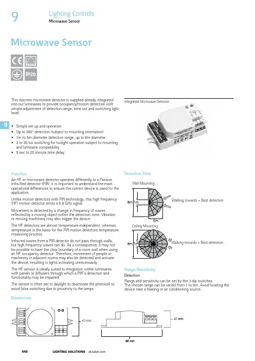
This discrete microwave detector is supplied already integrated into our luminaires to provide occupancy/motion detection with simple adjustment of detection range, time out and switching light level.• Simple set up and operation• Up to 360° detection (subject to mounting orientation)• 1m to 5m diameter detection range, up to 8m diameter • 2 to 30 lux switching for twilight operation subject to mounting and luminaire compatibility • 5 sec to 25 minute time delayFunctionAn HF or microwave detector operates differently to a Passive Infra-Red detector (PIR), it is important to understand the main operational differences to ensure the correct device is used for the application.Unlike motion detectors with PIR technology, this high frequency (HF) motion detector emits a 5.8 GHz signal.Movement is detected by a change in frequency of wavesreflected by a moving object within the detection zone. Vibration or moving machinery may also trigger the device.The HF detectors are almost temperature-independent, whereas temperature is the basis for the PIR motion detectors temperature measuring process.Infra-red waves from a PIR detector do not pass through walls, but high frequency waves can do. As a consequence, it may not be possible to have the clear boundary of a room wall when using an HF occupancy detector. Therefore, movement of people or machinery in adjacent rooms may also be detected and activate the device, resulting in lights activating unnecessarily.functionality may be impaired.avoid false switching due to proximity to the lamps. Integrated Microwave DetectorDetection ZoneDimensionsMicrowave SensorIP209Lighting Controls9Microwave SensorSet up and OperationPlease read all the information contained in these directions prior to any set up or servicing.Isolate the device from the mains power supply before carrying out any installation, maintenance or servicing.The device will generally be pre installed into a luminaire ready for set up with no additional installation or connection required.Light Level SettingThe chosen light response threshold can be infinitely varied from approx. 2 to 30 lux or disabled using the dip switches.Time SettingThe light can be set to stay ON for any period of time between approx. 5 seconds and a maximum of 25 minutes using the dip switchesAny movement detected before this time elapses will re-start the timer.There will be no twilight evaluation (daytime operation) for as long as the motion detector is switched on.Note: After the light switches OFF, it takes approx. 1 second before it is able to start detecting movement again.Luminaire Range CompatibilityThe device is designed for integration into our luminaires and is not available as a stand alone device.Luminaire ranges particularly suited to the integrated microwave sensor include: Tufflite, Crompack 5, Cercla, Modulay with panels, Varsity and Wavelite 2. The ‘IM’ prefix on compatible luminaires indicates inclusion of the microwave detector. Please contact your local Eaton sales engineer to discuss your requirements.Test SettingIn order to adjust the detection range during the day, the light level value must be set to daylight and time should be set to the minimum (approx. 5 seconds). The sensor is often set todaylight to deactivate the photocell to avoid false switching due to proximity to the lamps.Note: When initialising the detector into operation or after a power failure, the motion detector will switch on for the duration of the set time-value.ConnectionsConnect power supply as indicated in the terminal connection:Phase = LConnected phase = L’ Neutral conductor = NTechnical DataTrouble Shooting GuideMalfunction Cause RemedyCauseRemedyThe load will not workIncorrect light-control setting selected Load faultyMains switch OFFAdjust setting Replace load Switch ONThe load is always onContinuous movement in the detection zoneCheck zone settingThe load is on without any identifiable movementThe sensor is not mounted for reliably detection movement Movement occurred, but not identified by the sensor (movement behind wall, movement of small object in immediate lamp vicinity etc.)Securely mount enclosure Check zone settingThe load will not work despite movementRapid movements are being suppressed to minimise malfunctioning or the detection radius is too smallCheck zone setting************************************************************************************************************************Power Supply: 230V (+6%/-10%) 50/60Hz Maxload:400W Inductive Power consumption: <1WHF transmitter output: 5.8GHz <10mW ISM Band Range:Up to 5m Photo electric switch:2 to 30 lux Time setting:5 sec to 25 minAmbient temperature range: -10 to + 50°C (The luminaire ambient operating temperature may be more restricted)Housing material:UV stable Polycarbonate4479Lighting Controls9Microwave Sensor。

No.PF※※-OMJ0016-J Digital Flow Switch(Remote type sensor unit)PFM5##Safety Instructions 2 Model Indication and How to Order 10 Summary of Product parts 13 Mounting and Installation 14 Installation 14 Piping 16 Wiring 17 Troubleshooting 19 Error indication 20 Specification 21 Specifications 21 Characteristics data 23 Dimensions 25Safety InstructionsThese safety instructions are intended to prevent hazardous situations and/or equipment damage.These instructions indicate the level of potential hazard with the labels of "Caution", "Warning" or "Danger". They are all important notes for safety and must be followed in addition to International Standards(ISO/IEC)*1), and other safety regulations.*1) ISO 4414: Pneumatic fluid power -- General rules relating to systems.ISO 4413: Hydraulic fluid power -- General rules relating to systems.IEC 60204-1: Safety of machinery -- Electrical equipment of machines .(Part 1: General requirements)ISO 10218: Manipulating industrial robots -Safety.etc.Caution Caution indicates a hazard with a low level of risk which, if not avoided, couldresult in minor or moderate injury.Warning Warning indicates a hazard with a medium level of risk which, if not avoided,could result in death or serious injury.Danger Danger indicates a hazard with a high level of risk which, if not avoided, willresult in death or serious injury.Warning1. The compatibility of the product is the responsibility of the person who designs theequipment or decides its specifications.Since the product specified here is used under various operating conditions, its compatibility with specific equipment must be decided by the person who designs the equipment or decides its specifications based on necessary analysis and test results.The expected performance and safety assurance of the equipment will be the responsibility of the person who has determined its compatibility with the product.This person should also continuously review all specifications of the product referring to its latest catalog information, with a view to giving due consideration to any possibility of equipment failure whenconfiguring the equipment.2. Only personnel with appropriate training should operate machinery and equipment.The product specified here may become unsafe if handled incorrectly.The assembly, operation and maintenance of machines or equipment including our products must be performed by an operator who is appropriately trained and experienced.3. Do not service or attempt to remove product and machinery/equipment until safety isconfirmed.1. The inspection and maintenance of machinery/equipment should only be performed after measures toprevent falling or runaway of the driven objects have been confirmed.2. When the product is to be removed, confirm that the safety measures as mentioned above areimplemented and the power from any appropriate source is cut, and read and understand the specific product precautions of all relevant products carefully.3. Before machinery/equipment is restarted, take measures to prevent unexpected operation and malfunction.4. Contact SMC beforehand and take special consideration of safety measures if theproduct is to be used in any of the following conditions.1. Conditions and environments outside of the given specifications, or use outdoors or in a placeexposed to direct sunlight.2. Installation on equipment in conjunction with atomic energy, railways, air navigation, space, shipping,vehicles, military, medical treatment, combustion and recreation, or equipment in contact with food and beverages, emergency stop circuits, clutch and brake circuits in press applications, safety equipment or other applications unsuitable for the standard specifications described in the product catalog.3. An application which could have negative effects on people, property, or animals requiring specialsafety analysis.4. Use in an interlock circuit, which requires the provision of double interlock for possible failure by usinga mechanical protective function, and periodical checks to confirm proper operation.Safety InstructionsCaution1.The product is provided for use in manufacturing industries.The product herein described is basically provided for peaceful use in manufacturing industries.If considering using the product in other industries, consult SMC beforehand and exchange specifications or a contract if necessary.If anything is unclear, contact your nearest sales branch.Limited warranty and Disclaimer/Compliance RequirementsThe product used is subject to the following "Limited warranty and Disclaimer" and "Compliance Requirements".Read and accept them before using the product.Limited warranty and Disclaimer1. The warranty period of the product is 1 year in service or 1.5 years after the product is delivered,whichever is first.*2)Also, the product may have specified durability, running distance or replacement parts. Please consult your nearest sales branch.2. For any failure or damage reported within the warranty period which is clearly our responsibility,a replacement product or necessary parts will be provided.This limited warranty applies only to our product independently, and not to any other damage incurred due to the failure of the product.3. Prior to using SMC products, please read and understand the warranty terms and disclaimersnoted in the specified catalog for the particular products.*2) Vacuum pads are excluded from this 1 year warranty.A vacuum pad is a consumable part, so it is warranted for a year after it is delivered.Also, even within the warranty period, the wear of a product due to the use of the vacuumpad or failure due to the deterioration of rubber material are not covered by the limitedwarranty.Compliance Requirements1. The use of SMC products with production equipment for the manufacture of weapons of massdestruction (WMD) or any other weapon is strictly prohibited.2. The exports of SMC products or technology from one country to another are governed by therelevant security laws and regulation of the countries involved in the transaction. Prior to the shipment of a SMC product to another country, assure that all local rules governing that export are known and followed.CautionSMC products are not intended for use as instruments for legal metrology.Products that SMC manufactures or sells are not measurement instruments that are qualified by pattern approval tests relating to the measurement laws of each country.Therefore, SMC products cannot be used for business or certification ordained by the measurement laws of each country.■NOTE○Follow the instructions given below when designing, selecting and handling the product.●The instructions on design and selection (installation, wiring, environment, adjustment, operation,maintenance, etc.) described below must also be followed.*Product specifications•The direct current power supply used should be UL approved as follows.Circuit (Class 2) of maximum 30 Vrms (42.4 V peak) or less, with UL1310 Class 2 power supply unit or UL1585 Class 2 transformer.•The product is a UL approved product only if it has a mark on the body.•Use the specified voltage.Otherwise failure or malfunction can result.Insufficient supply voltage may not drive a load due to a voltage drop inside the product.Verify the operating voltage of the load before use.•Do not exceed the specified maximum allowable load.Otherwise it can cause damage or shorten the lifetime of the product.•Applicable operating fluid depends on the product.Check the details of the specifications before using.•Before designing piping confirm the pressure loss at the sensor from the pressure loss graph.Confirm pressure loss of the sensor from the characteristics data.•For the details of compressed air quality, refer to ISO 8573-1, 1.1.2 to 1.6.2.•Use the specified measurement flow rate and operating pressure.Otherwise it can cause damage to the product or inability to measure correctly.•Reserve a space for maintenance.Allow sufficient space for maintenance when designing the system.●Product handling*Installation•Tighten to the specified tightening torque.If the tightening torque is exceeded the mounting screws and brackets may damaged.If the tightening torque is insufficient, the product may be displaced and the mounting screws may come loose (Refer to page 14 "Mounting and Installation".)•Do not apply excessive stress to the product when it is mounted with a panel mount.Otherwise damage to the product and disconnection from the panel mount can result.•Ensure that the FG terminal is connected to ground when using a commercially available switch-mode power supply.•Do not drop, hit or apply excessive shock to the product.Otherwise damage to the internal parts can result, causing malfunction.•Do not pull the lead wire forcefully, or lift the product by the lead wire. (Tensile force 49 N or less)Hold the product body when handling, to prevent damage, failure or malfunction•For piping of the product, hold the piping with a spanner on the metal part of the product (Pipingattachment).Holding other parts with a spanner leads to may damage the product.•Any dust left in the piping should be flushed out by air blow before connecting the piping to the product.Otherwise damage or malfunction can result.•Refer to the flow direction of the fluid indicated on the product label for installation and piping.Remaining air can cause inability to measure accurately.•Do not mount the body with the bottom facing upwards.Remaining air can cause inability to measure accurately.•Do not insert metal wires or other foreign matter into the piping port.This can damage the sensor causing failure or malfunction.•Never mount a product in a location that will be used as a foothold.The product may be damaged if excessive force is applied by stepping or climbing onto it.•If there is a risk of foreign matter entering the fluid, install and pipe a filter or the mist separator at the inlet to avoid failure and malfunction.Otherwise damage or malfunction can result.And it can cause inability to measure accurately.Refer to the figure below for the recommended pneumatic circuit.*Wiring•Do not pull the lead wires.In particular, never lift a product equipped with fitting and piping by holding the lead wires.Otherwise damage to the internal parts can result, causing malfunction or disconnection of the connector. •Avoid repeatedly bending or stretching the lead wire, or placing heavy loads on itRepeated bending stress or tensile stress can cause damage to the sheath, or breakage of the wires.If the lead wire can move, fix it near the body of the product.The recommended bend radius of the lead wire is 6 times the outside diameter of the sheath, or 33 times the outside diameter of the wire insulation material, whichever is larger.Replace any damaged lead wire with a new one.•Wire correctly.Incorrect wiring can damage the product.•Do not perform wiring while the power is on.Otherwise damage to the internal parts can result, causing malfunction.•Do not route wires and cables together with power or high voltage cables.Otherwise the product can malfunction due to interference or noise and surge voltage from power and high voltage cables.•Confirm proper insulation of wiring.Poor insulation (interference from another circuit, poor insulation between terminals, etc.) can lead to excess voltage or current being applied to the product, causing damage.•Keep wiring as short as possible to prevent interference from electromagnetic noise and surge voltage.Do not use a cable longer than 30 m.Wire the DC (-) line (blue) as close as possible to the power supply.•When analogue output is used, install a noise filter (line noise filter, ferrite element, etc.) between the switch-mode power supply and this product.*Environment•Do not use the product in area that is exposed to corrosive gases, chemicals, sea water, water or steam.Otherwise failure or malfunction can result.•Do not use in a place where the product could be splashed by oil or chemicals.If the product is to be used in an environment containing oils or chemicals such as coolant or cleaning solvent, even for a short time, it may be adversely affected (damage, malfunction, or hardening of the lead wires)•Do not use in an area where electrical surges are generated.If there is equipment generates large electrical surges (solenoid type lifter, high frequency induction furnace, motor, etc.) close to the product, damage or failure of the internal circuit may occur. Take measures against the surge sources, and prevent the wires from coming into close contact.•Do not use a load which generates a surge voltage.When a surge-generating load such as a relay or solenoid is driven directly, use a product with a built-in surge absorbing element.•The product is CE/UKCA marked, but not immune to lightning strikes. Take measures against lightning strikes in the system.•Do not use the product in areas that are exposed to vibration or impact.Otherwise failure or malfunction can result.•Do not use the product in the presence of a magnetic field.This may lead to the malfunction of the product.•Prevent foreign matter such as wire debris from entering the product.Otherwise failure or malfunction can result.•Do not use the product in areas subject to large temperature cycle.Heating/cooling cycles other than ordinary changes in temperature can adversely affect the internal structure of the product•Do not expose the product to direct sunlight.If using in a location directly exposed to sunlight, use a suitable protective cover.Otherwise failure or malfunction can result.•Keep within the operating fluid temperature and operating temperatures range.The operating fluid temperature and operating temperature range is 0 to 50 o C.Operation below the minimum temperature limit may cause damage or operation failure due to frozen moisture in the fluid or air.An air dryer is recommended for elimination of drainage and water.Avoid sudden temperature changes even within the specified temperature range.•Do not operate close to a heat source, or in a location exposed to radiant heat.Otherwise malfunction can result.•The temperature between products rises when sticking is installed, and there is a possibility to influence the performance of the product.*Adjustment and Operation•Do not short-circuit the load.When the product load is short circuit, generated excess current lead to cause the damage of the product. •Supply the power when there is no flow.*Maintenance•Perform regular maintenance and inspections.There is a risk of unexpected malfunction of components due to the malfunction of equipment and machinery. •Turn off the power supply, stop the supplied air, exhaust the residual pressure and verify the release of air before performing maintenance.There is a risk of unexpected malfunction.•Perform drainage regularly.If condensate enters the outside, it can cause operating failure of pneumatic equipment.•Do not use solvents such as benzene, thinner etc. to clean the product.They could damage the surface of the body and erase the markings on the body.Use a soft cloth to remove stains.For heavy stains, use a cloth lightly dampened with diluted neutral detergent, then wipe up any residue with a dry cloth.*Other•If it has a restrictor, the flow adjustment valve may rotate due to vibration and change the flow rate. •Accuracy may vary by 2 to 3% if the customer removes or replaces the piping port themselves.: Each accessory is not assembled with the product, but shipped together.Accessories/Part number*: The table shows the specifications when a flow adjusting valve is included.■Installation•Refer to the flow direction of the fluid indication on the product label for installation and piping. Panel mounting•Insert Panel Mount Adapter B (supplied as an accessory) into Section A of Panel Mount Adapter A.Push Panel Mount Adapter B from behind until the display is fixed onto the panel.The pin of bracket engages the notched part of panel adapter A section C to fix the display.•The switch can be mounted on a panel with a thickness of 1 to 3.2 mm.•Refer to the dimension drawing (page 37) for panel cut-out dimensions.Bracket mounting•Mount the bracket using the mounting screws supplied. •The required tightening torque is 0.5 ± 0.05 N•m.Without flow adjustment valve (using ZS-33-M)With flow adjustment valve (using ZS-33-MS)•Install the product (with bracket) using the M3 screws (4 pcs.).•Bracket thickness is approximately 1.2 mm.•Refer to the dimension drawing of the bracket (page 37) for mounting hole dimensions.DIN rail mounting (using ZS-33-R )•Mount the DIN rail mounting parts using DIN rail mounting screws and joint screws supplied. •The required tightening torque of the DIN rail mounting screws and joint screws is 0.4±0.05 N•m.■PipingFor the metal piping attachments•Ensure that the metal piping attachments are tightened to the required torque (refer to the table below). •If the tightening torque is exceeded, the product can be broken. If the tightening torque is insufficient, the fittings may become loose.•When connecting piping to the product, a spanner should be used on the metal piping attachment only.Using a spanner on other parts may damage the product.•Avoid any sealing tape from entering inside the piping.•Ensure that there is no leakage from loose piping.For one-touch fittings•Insert the tube until it bottoms out, to ensure it cannot be pulled out.•Insertion with excessive force can cause damage.•Ensure that there is no leakage after piping.•Use this product within the specified operating pressure and temperature ranges.•Proof pressure is 1.0 MPa.■WiringWiring of connector•Connections should only be made with the power supply turned off.•Use separate routes for the product wiring and any power or high voltage wiring. Otherwise, malfunction may result due to noise.•Ensure that the FG terminal is connected to ground when using a commercially available switch-mode power supply. When a switch-mode power supply is connected to the product, switching noise will be superimposed and the product specification can no longer be met. This can be prevented by inserting a noise filter, such as a line noise filter and ferrite core, between the switch-mode power supply and the product, or by using a series power supply instead of a switch-mode power supply.Connecting/Disconnecting• When mounting the connector, insert it straight into the socket, holding the lever and connector body, and push the connector until the lever hooks into the housing, and locks.•When removing the connector, press down the lever to release the hook from the housing and pull the connector straight out.Connector pin numbers (on the lead wire)Internal circuit and wiring exampleAnalogue output: 1 to 5 VOutput impedance: 1 kΩAnalogue output: 4 to 20 mAMax. load impedance: 600 Ω (24 VDC)Min. load impedance: 50 ΩSelect response time (input): No voltage input (reed switch or solid state switch), 30 ms or more Select response time (input)The response time can be selected to improve the stability of the analogue output, if the output is unstable due to flow rate pulsation.How to select the response timeConnect the response time input wire (white) to GND. While connected, the response time will be 1.0 second, or 50 ms when not connected.TroubleshootingIf an operation failure occurs with the product, use the chart below to find out the cause of the problem. If none of the countermeasures seem to be applicable, or a replacement product operates normally when installed, the product may be faulty. A product can be damaged by the operating environment (system configuration etc). If the product seems to be faulty, please contact SMC.If the error cannot be reset after the above measures are taken, then please contact SMC.■Characteristics data●Analogue output characteristics*: Analogue output at maximum rated flow rate when CO2 is selected is 4.57 [V] for the voltage output type and 18.28 [mA] for the current output type.Model Max. rated flow[L/min]PFM510- -1 10 (5)PFM525- -1 25 (12.5)PFM550- -1 50 (25)PFM511- -1 100 (50) *: ( ): Fluid: CO2ModelMax. rated flow[L/min] PFM510- -2 10 (5)PFM525- -2 25 (12.5)PFM550- -2 50 (25)PFM511- -2 100 (50) *: ( ): Fluid: CO2●Flow adjustment needle revolution - Flow characteristics (reference value)●Pressure loss (at 350 [kPa])■DimensionsPFM5 -(N)01/(N)02/F01-1/2PFM5 -(N)01L/(N)02L/F01L-1/2PFM5 S-(N)01/(N)02/F01-1/2PFM5 S-(N)01L/(N)02L/F01L-1/2PFM5 -F02-1/2PFM5 -F02L-1/2PFM5 S-F02-1/2PFM5 S-F02L-1/2PFM5 -C/N -1/2PFM5 -C/N L-1/2PFM5 S-C/N -1/2PFM5 S-C/N L-1/2Panel cut-out dimensions*1: These are the minimum dimensions for bottom entry piping. If using straight entry piping, the material and tubing need to be taken into consideration when deciding panel cut-out spacing. *2: If a bend (R) is used, limit it to R3 or less. *3: Suitable for panel thickness of 1 to 3.2 mm.Bracket (ZS-33-M)Bracket (ZS-33-MS)Flow adjustment valveANone54 +0.5 0With flow adjustment valve74+0.5 0Lead wire and connector (ZS-33-D) Connector cover (ZS-33-F)4-14-1, Sotokanda, Chiyoda-ku, Tokyo 101-0021 JAPANTel: + 81 3 5207 8249 Fax: +81 3 5298 5362URL https://Note: Specifications are subject to change without prior notice and any obligation on the part of the manufacturer.。

ApplicationsFlow switch for monitoring and displaying the relative mass flow rates of liquid media in the range from 0.03 to 3 m/s (0.1 to 9.84 ft/s):•Flowphant T DTT31 − with threaded connections or compression fitting •Flowphant T DTT35 − with process connections for hygienic applications Applications:•Monitoring of cooling water circuits of pumps, turbines, compressors and heat exchangers•Monitoring of pump functions •Leak monitoring in process pipes •Monitoring of lubrication circuits•Filter monitoring in the beverages industry Your benefitsThe compact flow switch impresses with state-of-the-technology:•Virtually zero pressure loss•FieldCare for quick configuration and reliable storage of device settings •Optional: 4 to 20 mA analog output for outputting the flow as a percentage •Optional: second switch output or 4 to 20 mA analog output for temperature monitoring•Onsite function check and process information with digital display on device •Top housing section which can be rotated 310° and rotatable display mean measured values can be read in all installation positions •Marine approval•3-A mark and EHEDG certificate for DTT35Products Solutions ServicesTechnical InformationFlowphant T DTT31, DTT35Flow switchTI00125R/09/EN/03.18714155662018-02-15Flowphant T DTT31, DTT352Endress+HauserTable of contentsFunction and system design (3)Measuring principle ............................3Measuring system .. (3)Input (5)Measured variable .............................5Measuring range (5)Output (5)Output signal ................................5Signal on alarm ...............................5Load ......................................5Range of adjustment ...........................5Switching capacity .............................6Inductive load ................................6Power supply (6)Electrical connection ...........................6Supply voltage ...............................7Current consumption (7)Performance characteristics (7)Reference operating conditions ....................7Maximum measured error .......................7Switch point non-reproducibility ...................9Temperature gradient ..........................9Sensor response time ...........................9Long-term drift ...............................9Long-term reliability ...........................9Switch output response time ......................9Analog output ...............................9Installation (10)Orientation ................................10Installation instructions ........................10Inlet and outlet runs ..........................11Environment (12)Ambient temperature range .....................12Storage temperature ..........................12Degree of protection ..........................12Shock resistance .............................12Vibration resistance ...........................12Process (12)Process temperature range ......................12Process pressure range .........................12Flow limit .................................12Operational range ............................12Mechanical construction ....................13Design, dimensions ...........................13DTT31 design, dimensions of the process connections ....13DTT35 design, dimensions of the process connections ....14Weight ...................................14Materials ..................................14Operability (16)Operating concept ............................16Local operation ..............................16Remote operation with PC .. (18)Certificates and approvals (19)Electromagnetic compatibility (EMC)...............19Hygiene standard ............................19Parts in contact with medium ....................19Marine approval .............................19Other standards and guidelines ...................19Material certification ..........................19Ordering information .......................19Accessories . (20)Device-specific accessories ......................20Communication-specific accessories ................21Supplementary documentation (23)Technical Information .........................23Operating Instructions .........................23Flowphant T DTT31, DTT35Endress+Hauser 3Function and system designMeasuring principleThe device measures the mass flow of a liquid medium using the calorimetric measurement method.The calorimetric measuring principle is based on the cooling of a heated temperature sensor. Heat is removed from the sensor by forced convection due to medium flowing by. The extent of this heat transfer depends on the flow velocity of the medium and the difference in temperature between the sensor and the medium (King's Law). The higher the flow velocity or the mass flow of the medium,the greater the temperature sensor cooling.Measuring systemOverviewFlowphant T DTT31, DTT354Endress+HauserDC voltage version (DC)PNP switch output of electronics.Power supply e.g. with a power supply unit.Preferably in connection with programmable logic controllers (PLC) or for controlling a relay.A 1x PNP switch outputB 2x PNP switch outputC PNP switch output with additional analog output 4 to 20 mA(active)1Transmitter power supply unit, e.g. RNB1302Load (e.g. programmable logic controller, process control system, relay)3Display unit e.g. RIA452 or recorder e.g. Ecograph T or Minilog B (at 4 to 20 mA analog output)1 "Easy Analog RNB130" transmitter power supply unit:Primary switched-mode power supply for sensors. Space-saving DIN rail mounting as per IEC 60715.Wide-range input: 100 to 240 V AC nominal voltage; output: 24 V DC , max. 30 V in the event of an error;Nominal current: 1.5 A. Connection to single-phase alternating current networks or to two phase conductors of three-phase supply networks.2 process display units RIA452:If you would like to read off the instantaneous temperature value not only locally, but also directly from a control room or in the PC network, for example, the process display unit RIA452 is one possible solution: Digital process display unit in 96 to 96 mm (3.78 to 3.78 in) panel mountedFlowphant T DTT31, DTT35Endress+Hauser 5housing for monitoring and displaying analog measured values with pump control and batchfunctions. Multicolored 7-digit 14-segment LC display with bargraph representation. Configuration and measured value visualization via RS232 interface and PC configuration software.3 Universal Graphic Data Manager Ecograph T, data logger Minilog B:If you would not only like to read off the instantaneous temperature value, but also record, analyze and display it directly in a control room or in the PC network, for example, then the following options are available:•Universal Graphic Data Manager Ecograph T in 144 mm (5.67 in) x 144 mm (5.67 in) panelmounted housing for the electronic capture, display, recording,analysis, remote transmission and archiving of analog and digital input signals. Multichannel data recording system withmulticolored TFT display (145 mm (5.7 in)) screen size), galvanically isolated universal inputs (U,I, TC, RTD, pulse, frequency), digital inputs, transmitter power supply, limit relays, communication interfaces (USB, Ethernet, optionally RS232/485), 128 MB internal memory, external SD card and USB stick. The Field Data Manager (FDM) software supports data analysis at the PC, the device can be configured with FieldCare or the integrated Web server.•Data logger Minilog B measured value recorder with 2 input channels for recording and storing analog and digital values. Internal 128 kB memory for max. 84 000 measured values.Configuration and measured value visualization via RS232 interface and PC configuration software. Optionally available with telealarm function.InputMeasured variable•Flow velocity of liquid media (calorimetric measuring principle)•Temperature (RTD), optionally for two switch outputs or additional analog outputMeasuring rangeFlow 0.03 to 3 m/s (0.1 to 9.84 ft/s), as relative value between 0 to 100%; maximum display resolution: 1%Temperature–20 to +85 °C (–4 to +185 °F); display resolution: 1 °C (1 °F)OutputOutput signalDC voltage version (short-circuit proof version):•1x PNP switch output (flow) or•2x PNP switch outputs (flow or temperature, configurable) or•1x PNP switch output and 1x 4 to 20 mA output, active (flow or temperature, configurable)The analog output reports the measured flow as a relative value expressed as a percentage of the set measuring range.Signal on alarmAnalog output: signal on alarm according to NAMUR NE43Underranging Linear drop to 3.8 mA OverrangingLinear rise to 20.5 mASensor breakage; sensor short-circuit ≤3.6 mA or ≥ 21.0 mA (output 21.7 mA is guaranteed for setting ≥ 21.0 mA)Switch outputsIn the safe state (switch open)LoadMax. (V power supply - 6.5 V) / 0.022 A (current output)Range of adjustmentSwitch output Switch point (SP) and switchback point (RSP) in increments of 1% with min.hysteresis of 5%Damping User-configurable 0 = off (no damping) or 10 to 40 s in increments of 1 s Unit%, optionally °C, °F (with two outputs and temperature monitoring)Flowphant T DTT31, DTT356Endress+HauserSwitching capacity DC voltage version:Switch status ON Ia ≤ 250 mA Switch status OFF Ia ≤ 1 mA Switching cycles > 10,000,000Voltage drop PNP ≤2 VOverload protectionSwitching current checked automatically; switched off in event of overcurrent,switching current checked again every 0.5 s; max. capacitive load: 14 µF for max.supply voltage (without resistive load); periodic disconnection from a protective circuit in event of overcurrent (f = 2 Hz) and "Warning" displayedInductive loadTo prevent electrical interference, only operate an inductive load (relays, contactors, solenoid valves)with a direct protective circuit (free-wheeling diode or capacitor).Power supplyElectrical connectionPlug connectorA M12x1 connectorB Valve connector M16x1.5 or NPT ½"Device connectionDC voltage version with M12x1 connector1Flowphant T with M12x1 connectorFlowphant T DTT31, DTT35Endress+Hauser 7DC voltage version with M16x1.5 valve connector or NPT ½"Supply voltage DC voltage version: 18 to 30 V DC (reverse polarity protection)Behavior in the event of overvoltage (>30 V)•The device works continuously up to 34 V DC without any damage•No damage in event of transient overvoltage up to 1 kV (according to EN 61000-4-5)•If the supply voltage is exceeded, the specified characteristics are no longer guaranteed Behavior in the event of undervoltageIf the supply voltage falls below the minimum value, the device switches off in a defined manner (status as if not supplied with power = switch open)Current consumption < 100 mA (no-load) at 24 V DC , max. 150 mA (no-load); with reverse polarity protectionPerformance characteristicsThe percentage information in the "Performance characteristics" section refers to the full scale value or the set maximum value (100% value) of the monitoring range.Reference operating conditionsAs per DIN IEC 60770 or DIN IEC 61003T = 25 °C (77 °F) ± 5 °C (9 °F)–Relative humidity 45 to 75%–Ambient air pressure 860 to 1 060 kPa (124 to 153 psi), water testing medium –Supply voltage U = 24 V DC Maximum measured errorFlowThe device records flow velocities relatively in relation to a set flow monitoring range (0 to 100 % as the display value). Absolute measurement of the flow velocity or the mass flow is not possible. The sensitivity of the calorimetric flow sensor changes with the flow velocity of the medium. It increases with decreasing flow velocity (example: in the case of water, the greatest sensor sensitivity is in the range from 0.03 to 0.5 m/s).Flowphant T DTT31, DTT358Endress+Hauser2Standard characteristicA, B Configured flow monitoring ranges (example)LOWF 0%: Setting for the minimum flow velocity occurring in monitoring range A or B (0% value)HIF 100%: Setting for the maximum flow velocity occurring in monitoring range A or B (100% value)Temperature•Accuracy2 K (3.6 °F)•Reproducibility1 K (1.8 °F)•Influence of ambient temperature 0.05%/K of full scale valueFlowphant T DTT31, DTT35Endress+Hauser 9Switch point non-reproducibilityThe values indicated only apply to the device itself without factoring in the temperature-dependent change in the thermophysical properties of the medium. For this reason, it is advisable to commission the device and set the switch points at the process temperature → 161)For a Reynolds number > 10,000Temperature gradientIf the medium experiences a temperature change of ≥ 0.5 K/min, temporary display drifts are possible which can exceed the specified non-reproducibility values of the switch point.Sensor response time 6 to 12 sLong-term drift < 0.5% per year under reference operating conditionsLong-term reliabilitySwitch output response time 100 msAnalog outputMaximum measured error Switch point and display deviation + 0.1%Rise time t 90≤200 ms Settling time t 99≤500 msFlowphant T DTT31, DTT3510Endress+HauserInstallationOrientationNo restrictions. However, self-draining in the process must be guaranteed. If there is an opening to detect leaks at the process connection, this opening must be at the lowest possible point.•The display can be rotated electronically by 180 °.•The top housing section can be rotated mechanically by up to 310 °.6Installation in hygienic processesA Sanitary connection according to DIN 11851 (PL, PG, PH connection), only in conjunction with EHEDG-certified and self-centering sealing ring as per EHEDG position paperB Varivent and APV-Inline (LB, LL, HL connection)CClamp according to ISO 2852 (DB, DL connection), only in conjunction with seal as per EHEDG position paperThe following action must be taken if a sealing ring (O-ring) or seal fails:•Remove the thermometer, clean the thread and the O-ring joint/sealing surface •Replace the sealing ring or seal •Perform CIP after installationIn the case of weld-in connections, exercise the necessary degree of care when performing the welding work on the process side:•Suitable welding material•Flush-welded or with welding radius > 3.2 mm (0.13 in)•No recesses, folds or gaps•Honed and polished surface, Ra ≤ 0.8 mm (0.031 in)As a general rule, the thermometers should be installed in such a way that does not impact their ability to be cleaned (the requirements of the 3-A Standard must be observed). The Varivent® couplings enable flush-mount installation.Inlet and outlet runsThe thermal measuring principle is sensitive to disturbed flow conditions.•As a general rule, install the measuring device as far away as possible from any flow disturbances. For further information → ISO 14511.•If possible, install the sensor upstream from fittings such as valves, T-pieces, elbows etc.•To attain the specified level of accuracy of the measuring device, the inlet and outlet runs mentioned below must be maintained at the very minimum.•If several flow disturbances are present, maintain the longest specified inlet run.1Reduction 2Expansion390° elbow or T-piece 4Pump5Control valve62x 90° elbow, 2- or 3-dimensionalEnvironmentAmbient temperature range –40 to +85 °C (–40 to +185 °F)Storage temperature –40 to +85 °C (–40 to +185 °F)Degree of protectionIP65M16 x 1.5 or NPT ½", valve connector IP66M12 x 1 connectorShock resistance 50 g as per DIN IEC 68-2-27 (11 ms)Vibration resistance•20 g as per DIN IEC 68-2-6 (10-2000 Hz)•4 g as per marine approvalProcessProcess temperature range–20 to +85 °C (–4 to +185 °F)The sensor can be exposed to process temperatures up to 130 °C (266 °F) without being damaged.The monitoring system switches off automatically at T ≥ 85 °C (185 °F) and starts again at T ≤85 °C (185 °F).Process pressure rangeMaximum permissible process pressure P max ≤ 10 MPa = 100 bar (1 450 psi)The maximum process pressure for the conical metal-metal process connection (MB option) for the device is 1.6 MPa = 16 bar (232 psi).Flow limit Liquids: 0 to 3.0 m/s (0 to 9.84 ft/s)Operational rangeLiquids: 0.03 to 3.0 m/s (0.1 to 9.84 ft/s)Mechanical constructionAll dimensions in mm (in)L = insertion lengthM12x1 connector as per IEC 60947-5-2Valve connector M16x1.5 or NPT ½" as per DIN 43650A/ISO 44007Process connection versions8Process connection versionsAll dimensions in mm (in).L = insertion length LWeight Approx. 300 g (10.58 oz), depends on process connection and sensor length Materials•Process connection AISI 316L–Surfaces in contact with the process in hygienic version with surface quality Ra ≤0.8 µm (31.5 µin)–Coupling nut AISI 304•AISI 316L housing, with surface quality R a ≤ 0.8 µm (31.5 µin)O-ring between housing and sensor module: EPDM•Electrical connection–M12 connector, exterior AISI 316L, interior polyamide (PA)–Valve connector, polyamide (PA)–M12 connector, exterior 316L–Cable sheath polyurethane (PUR)–O-ring between electrical connection and housing: FKM•Display, polycarbonate PC-FR (Lexan®)Seal between display and housing: SEBS THERMOPLAST K®•Keys, polycarbonate PC-FR (Lexan®)OperabilityOperating concept Position of the display and operating elementsLocal operation Menu-guided operation using operating keys.Operation, visualization and maintenance with PC and FieldCare PC configuration software.Remote operation with PC1PC with FieldCare configuration software2Configuration kit TXU10-AA or FXA291 with USB port3Flow switchIn addition to the operating options listed in the previous "Onsite operation" section, furtherinformation about the Flowphant T is available via the FieldCare configuration software:Certificates and approvalsElectromagnetic compatibility (EMC)EMC to all relevant requirements of the IEC/EN 61326-series and NAMUR Recommendation EMC (NE21). For details, refer to the Declaration of Conformity.Maximum fluctuations during EMC-tests: < 1 % of measuring span.Interference immunity to IEC/EN 61326-series, requirements for industrial areas Interference emission to IEC/EN 61326-series, electrical equipment Class BHygiene standard•EHEDG certification, TYPE EL CLASS I. Permitted process connections in accordance with EHEDG,see 'P rocess connections'section → 13•3-A Authorization No. 1144. 3-A Sanitary Standard. Permitted process connections in accordancewith 3-A, see also "Process connections" section•3-A marked process connections → 14Parts in contact with medium The thermometer parts in contact with the medium meet the following European regulations:•(EC) No. 1935/2004, Article 3, Paragraph 1, Articles 5 and 17 on materials and articles intendedto come into contact with food.•(EC) No. 2023/2006 on good manufacturing practice (GMP) for materials and articles intended tocome into contact with food.•(EC) No. 10/2011 on plastic materials and articles intended to come into contact with food.•All surfaces in contact with the medium are free from materials derived from bovine animals orother livestock (ADI/TSE)Marine approval Information on the "Type Approval Certificates" currently available (DNVGL, BV, etc.) can be obtainedfrom the sales organization.Other standards and guidelines •IEC 60529Degrees of protection provided by enclosures (IP code)•IEC/EN 61010-1Protection Measures for Electrical Equipment for Measurement, Control, Regulation and Laboratory Procedures•NAMURInternational user association of automation technology in process industries (www.namur.de)•NEMAUnited States National Electrical Manufacturers Association.Material certification The material certificate 3.1 (according to standard EN 10204) can be requested separately. The"short form" certificate includes a simplified declaration with no enclosures of documents related tothe materials used in the construction of the individual sensor. It does, however, guarantee thetraceability of the materials through the identification number of the thermometer. The data relatedto the origin of the materials can subsequently be requested by the client if necessary.Ordering informationDetailed ordering information is available from the following sources:•In the Product Configurator on the Endress+Hauser website: -> Click "Corporate"-> Select your country -> Click "Products" -> Select the product using the filters and search field ->Open product page -> The "Configure" button to the right of the product image opens the ProductConfigurator.•From your Endress+Hauser Sales Center: Product Configurator - the tool for individual product configuration•Up-to-the-minute configuration data•Depending on the device: Direct input of measuring point-specific information such asmeasuring range or operating language•Automatic verification of exclusion criteria•Automatic creation of the order code and its breakdown in PDF or Excel output format•Ability to order directly in the Endress+Hauser Online ShopAccessoriesDevice-specific accessories Welding boss with sealing taperCollar welding bossWelding boss with sealing taper (metal-metal)Flowphant T DTT31, DTT35Endress+Hauser21Compression fitting1)SS316 clamping ring: can only be used once. Once released the compression fitting cannot be repositioned on the thermowell. Fully adjustable immersion length on initial installation2)PTFE/Silopren ® clamping ring: can be reused, once released the fitting can be moved up and down the thermowell. Fully adjustable immersion lengthCommunication-specific accessoriesCoupling; connecting cableFlowphant T DTT31, DTT3522Endress+Hauser4114.8(0.58)15Dimensions in mm (in)23Configuration kitConfiguration softwareThe FieldCare 'D evice Setup' configuration programs can be downloaded free of charge from the Internet at:/fieldcareFieldCare ’Device Setup’ can also be ordered from an Endress+Hauser sales office.Flowphant T DTT31, DTT35Endress+Hauser 23Supplementary documentationTechnical Information•Easy Analog RNB130: TI120R/09/en•Process display unit RIA452: TI113R/09/en•Universal data manager Ecograph T: TI01079R/09/en •Data logger Minilog B: TI089R/09/enOperating Instructions Flow switch Flowphant T DTT31, DTT35: BA00235R/09/en。
功能及技术要求(1)微波车辆检测器设置在路侧,安装在路侧的专门的立柱上,采用数字双雷达微波检测技术,能可靠地检测任何车辆,包括从摩托车到多轴、高车身的车辆,拖车应作为一辆车检测。
可检测路上每一车道所通过的车辆数、车辆速度、车道占有率、单车速度等参数。
(2)探测区域•检测射角(垂直面):65°•检测方位角:7°•作用距离:1.8~76米•侧置距离:适用于任何侧移量(3)检测精度•车流量精确度:任何单一车道流量>95%,总流量>98%•单车车速精度误差:>97%,10~250Km/H•平均车速精度误差:>97%,10~250Km/H•车道占有率精度误差:小于±5%,即使是在交通拥堵时段•探测车道数:每个检测器能够检测20条车道。
•按车辆长度可分8种车型,按车辆速度可分15种车型,参数可自行设置•精确的识别能力,即使车辆有多达50%的部分被障碍物遮挡亦可被识别(4)工作频率:24.125GHz(K-波段)(5)传输信号带宽:245MHz(6)功率消耗:8W(7)采样周期:最小10秒,可由用户自行设定(8)检测器配备至少两个RS-232/485通信接口,一个用于便携计算机,另一个用于传输至连通高速公路监控中心计算机,传输速率为2400~115200bps可调。
(9)设备应配有过电压和浪涌电压保护装置,在雷击时设备应不受影响,做到在高速公路使用环境下均能保证设备正常工作。
(10)检测器具有存储功能,内存容量16M。
如果通信中断,恢复后可由通信端口下载历史数据到便携电脑或监控中心。
(11)机箱设置于立柱上,用于放置电源、浪涌保护器、信号传输设备等。
采用镀锌钢板制作,表面采用涂/喷塑防腐处理。
机箱必须能够适应全天候工作条件,防护等级IP65。
(12)MTBF:90000小时。
设备能够连续不间断工作,每天24小时,每周7天。
(13)工作电源:12~24V DC/AC(14)工作环境•温差:-35℃~+70℃湿度:95%RH。
SPECTR微波车辆检测器用户手册俄罗斯奥利维亚公司一、系统简介SPECTR微波交通检测器Microwave Vehicle Detector(简称检测器)是基于非接触式探测方式线性调频的超高频信号原理,对路面发射微波,通过对回波信号进行高速实时的数字化处理分析,检测车流量、速度、车道占有率和车型等交通流基本信息的非接触式交通检测器。
SPECTR微波交通检测器主要应用于高速公路、城市快速路、普通公路交通流量调查站和桥梁的交通参数采集,提供车流量、速度、车道占有率和车型等实时信息,此信息可用隔离接触器连接到现行的控制器或通过串行通信线路连接到其它系统,为交通控制管理、信息发布等提供数据支持。
图1 SPECTR微波车辆检测器检测器可安装于路侧立柱或类似结构上,具有安装维护方便,不用破坏路面,不影响交通(不需要停车封路),技术先进,成本低等特点。
且安装调试时,具有专业的设备调试软件辅助,能快速准确的对设备进行调试安装。
设备提供数据实时传输、数据保存、数据下载功能。
对于数据包我们提供专业的软件,可对数据进行分析处理,生成所需的文字或图像报表,提高工作效率,让您事半功倍。
二、工作原理1.微波车辆检测器工作原理微波车辆检测器是一种用于检测交通状况的检测器,它利用连续频率调制波(FMCW)实现对多车道车辆的实时检测。
SPECTR检测器发射一束微波同时接收物体(目标)反射波,根据反射回来的波形及频率差异来判别车辆、车型、车速和车道。
所发射微波的中心频率为10.525GHz,频率带宽为40~50MHz,发射的微波断面分辨率为0.6m。
图2 连续频率调制波示意图2.微波特性非接触式微波探测:应用微波原理,侧面安装,通过微波探测得出实时检测结果,与线圈、视频等其它检测方式,具有不破损路面、安装维护不阻断交通、全天候工作、不受环境影响等等优点。
全天候工作:与其他交通检测技术不同的是,检测器采用了3 厘米波长的微波,不受雨滴,冰雹和雪花等影响,可以实现全天候工作。
1微波车辆检测器SmartSensor-125Smart Sensor利用了最先进的数字波雷达检测技术,同时检测多达10条车道的车道占用率、交通流量以及车速,属于调频连续波雷达。
Smart Sensor通过利用10.525GHz(X-波段)的工作频率来采集交通数据。
SS125微波车辆检测器通常安装在扇形区域内发射连续的低功率调制微波,并在路面留下一条阴影,形成微波检测区域。
当车辆进入检测区时,车辆检测区根据车辆返回的回波,测算出车辆的交通信息(车流量、车速、车道占有率),并将处理后的数据通过通讯设备上传至监控中心或直接储存在本地。
当现场设备安装完成后,Smart Sensor便会自动进行设置、检测,而且几乎不需要现场维护,并可以进行远程重新设置。
连接SS125电缆到Smart Sensor单元(1)将电缆接口连接到Smart Sensor单元底部的25针接口上,(2)将电缆扎在杆子上,一定要避免电缆拉的过紧。
连接SS125电缆到接线箱标准的Smart Sensor电缆是由六对双绞线组成的,每对双绞线由一条黑线、一条红线和一条屏蔽线组成,并且其外部有一层保护,每对双绞线的黑红两条线上都有一个数字编号,从1到6。
下表是电缆每根引出线连接到接线箱的说明:表1.1Tab1.1典型的安装需要将-DC连接到直流电源的负极,+DC连接到直流电源的正极。
直流供电电源必须提供8W、12-36VDC连续的电源,并且启动电源的瞬时功率(50ms)要达到15-20W。
接下来,再将RS232或RS485通讯线连接到各自的接口。
图1.3Fig 1.3利用Smart Sensor管理软件配置Smart Sensor单元Smart Sensor可以连接到笔记本电脑上,用于现场设置和校定或连接到有线或无限Modem上,用于远程设置。
请按照下面的指导将Smart Sensor单元连接到PC或Modem的串口上图1.4Fig 1.4表1.2Tab1.2表1.3Tab1.3图1.4Fig 1.4在这里,有两种可利用的方式连接Smart Sensor单元:(1)连接一个DB9针的串行通讯电缆到您的计算机上,或使用RS232转USB的转接线连接到笔记本电脑上(通常笔记本电脑没有RS232接口)标准的DB9针RS-232传输方式;(2)使用USB转RS485的转接线连接到笔记本电脑。
目录前言................................................................................................... 错误!未定义书签。
一. 硬件介绍、产品认证................................................................ 错误!未定义书签。
1.1硬件介绍 ............................................................................... 错误!未定义书签。
1.2产品认证 ............................................................................... 错误!未定义书签。
二.工作法则 ....................................................................................... 错误!未定义书签。
2.1.工作原理 ............................................................................... 错误!未定义书签。
2.2.车辆检测 ............................................................................... 错误!未定义书签。
2.3.数据输出 ............................................................................... 错误!未定义书签。
三.设备的应用及安装 ......................................................................... 错误!未定义书签。
3.1.设备装箱列表 ........................................................................ 错误!未定义书签。
3.2.运用领域 ............................................................................... 错误!未定义书签。
3.3.设置方式 ............................................................................... 错误!未定义书签。
3.4.安装工作流程 ........................................................................ 错误!未定义书签。
3.5射角调校说明 ........................................................................ 错误!未定义书签。
四.控制软件说明 ................................................................................ 错误!未定义书签。
4.1.软件说明 ............................................................................... 错误!未定义书签。
4.2.车量统计介面 ........................................................................ 错误!未定义书签。
4.3微波能量显示接口 ................................................................. 错误!未定义书签。
4.4.文字信息显示介面 ................................................................. 错误!未定义书签。
五.道路调校设定程序说明 .................................................................. 错误!未定义书签。
5.1.各种参数介绍 ........................................................................ 错误!未定义书签。
5.2. 串联通讯界面设定................................................................ 错误!未定义书签。
5.3.安装方式选择 ........................................................................ 错误!未定义书签。
5.4.侦测器参数设定..................................................................... 错误!未定义书签。
5.5.车道设定 ............................................................................... 错误!未定义书签。
5.6.速度调校 ............................................................................... 错误!未定义书签。
5.7.占有率调校............................................................................ 错误!未定义书签。
5.8.长车设定 ............................................................................... 错误!未定义书签。
六.数据传送方式与信息管理............................................................... 错误!未定义书签。
6.1.有线数据的传输..................................................................... 错误!未定义书签。
6.2. 无线数据的传输 ................................................................... 错误!未定义书签。
6.3 道路数据的储存与管理 ......................................................... 错误!未定义书签。
七.用户须知 ....................................................................................... 错误!未定义书签。
7.1.注意事项 ............................................................................... 错误!未定义书签。
7.2.侦测器识别............................................................................ 错误!未定义书签。
7.3.售后服务 ............................................................................... 错误!未定义书签。
7.4.维修方式 ............................................................................... 错误!未定义书签。
前言随着我国经济快速发展和城市规模不断扩大,各种交通需求不断增加,智能交通系统(又称"智能运输系统",Intelligent Transportation Systems,ITS)。
在我国逐渐得到了广泛应用和快速发展。
车辆检测技术是智能交通系统的重要组成部分,交通智能化管理需要通过车辆检测方式采集客观、有效的道路交通信息,获得交通流量、车速、道路占有率、车间距、车辆类型等基础数据,从而有目的地实现监测、控制、分析、决策、调度和疏导等智慧化手段。
W4W-TMS1055应用调频连续波(FMCW)微波侦测技术和高速数字信号处理(DSP)技术,该产品能够同时分辨多车道的侦测区域,以及不同种类之车型,并计算出车速、车流量与分析车道的可运用于红绿灯秒差控制器等智能交通管理系统中,能够为城市繁忙的交通道路,提供准确且可靠的最佳管理。
同时也适合于高速公路、市区道路、郊区公路、隧道、桥梁等等的智慧交通管理与道路车流量检测,有着广泛的使用空间和领域占用率,能适应各种恶劣环境,为全天候道路提供全天候实时信息,优点是在恶劣气候下性能出色,可以全天候工作、可检测静止的车辆、直接检测速度、可以侧向方式检测多车道、安装维护方便,W4W-TMS1055的采样数据包括:车流量、车道占有率、车辆的平均速度、车辆类型、车间距。
一.硬件介绍、产品认证1.1硬件介绍W4W-TMS1055-A侧向安装型微波车流量检测仪设备简介:W4W-TMS1055-A是一款高性能的微波车流量检测仪,该设备为侧向安装在道路的两旁,能够通过雷达波的侦测实时侦测道路上的车流量、车道占有率、车辆的平均速度、车辆类型、车间距等重要资料,可以为交通管理提供决策支持和资料支持,为交通智能化提供方便可靠地解决方案。
基本性能中心频率10.525 GHz频带宽度45MHz~50MHz输出功率20mW天线波束水平角9°天线波束垂直角65°侦测范围 1.5~80m车道分辨率0.8m最大侦测车道数8车道(侧向安装)设备包装尺寸长*宽*高(30*30*11cm)环境条件存储温度-50℃~+85℃工作温度范围-40℃~+75℃工作湿度95%RH(无冷凝)风速最大150km/h不降低其性能雨量最大100mw/h冲击5g @10ms半正弦波振动2g rms. up to 200Hz供电电源需求12至36V DC @ 10W 115V AC (选用)界面串行接口(1):RS-232 串行接口(2):RS-485(选用) W4W-TMS1055-B正向安装型微波车流量检测仪设备简介:W4W-TMS1055-B是一款高性能的微波车流量检测仪,该设备为正向安装在道路上的龙门架上,能够通过雷达波的侦测实时侦测正向车道上的车流量、车道占有率、车辆的平均速度、车辆类型、车间距等重要资料,可以为交通管理提供决策支持和资料支持,为交通智能化提供方便可靠地解决方案。